1. Introduction
Transformers are essential equipment in power transmission and distribution grids. The transformer windings generate a great deal of heat when operating under high loads for long periods [
1,
2]. The high temperature accelerates the ageing and decomposition of transformer insulation materials [
3,
4,
5], resulting in an inter-turn short circuit and even leading to transformer burnout. Efficient heat dissipation of transformer winding is a crucial and challenging point in engineering. The iron core and windings of the oil-immersed transformer are placed in a tank filled with transformer oil. The oil is used for insulation protection and arc suppression. More importantly, the oil can carry away the heat generated by the windings, transport it to the transformer housing, and dissipate it to the surrounding environment [
6]. The insulation paper–oil composite structure is an integral part of the insulation system of oil-nature–air-nature (ONAN) transformers [
7]. The heat exchange method on the insulation paper–oil contact surface of ONAN transformers is natural convective heat transfer [
8]. The heat transfer intensity is characterized by natural convective heat transfer coefficients [
9]. However, the insulation paper is a poor thermal conductor. Insulation paper’s rough surfaces and a narrow oil channel seriously impede the heat dissipation between the winding and the oil. In addition, the poor accuracy of the natural convective heat transfer coefficient determined by the characteristic number equation leads to significant deviations in winding temperature field calculations. Thus, the heat transfer mechanism on the contact surface needs to be clarified.
Some scholars have studied the natural convective heat transfer coefficient by employing numerical simulation and physical experiments and have obtained many interesting results. Gong et al. [
10] obtained convective heat transfer coefficients through the characteristic number equation. They carried the coefficients into the ONAN transformer finite volume analysis model to study the transformer hot-spot temperature, with simulated values 7.3% higher than the experimental results. E. Rahimpour [
11] presented a mathematical thermal model for disk-type transformer winding to calculate the temperature distribution. They found that the geometry of the zigzag cooling oil channel affects the hydrostatic pressure and changes the flow state of the insulation oil, thus changing the convective heat transfer performance. Moreover, Rahimpour verified the validity and accuracy of the modelling results with measured experimental data. P. Córdoba et al. [
12] built an experimental device to simulate a representative slice of the transformer, adopted a purpose-built PIV setup to obtain the flow velocity field, and observed the heat plume formation, detachment, and disintegration in the experimental setup. The transient evolution was measured, and it was found that the convection was stronger and the heat transfer coefficient was greater during the start-up transient. However, the effect of insulation paper on winding heat dissipation was not evaluated in the above study, as the paper structure was ignored. Liu [
13] investigated the effect of insulation paper on the winding temperature distribution by establishing a fluid–thermal coupled numerical model. When the model contains insulation paper, the overall temperature of the disc winding increases, and the radial temperature gradient of the winding increases with a maximum temperature difference of 20 K. The model results were verified by experimental data of the platform on a disc-type winding. Zhang et al. [
14] investigated the effect of nanofluids on natural convection heat transfer in disk windings with insulating paper by numerical modelling. An oil-based nanofluid can effectively improve the heat transfer coefficient at the solid–liquid interface, and nanoparticles with a volume fraction of 1% can reduce the hot-spot temperature of the winding by more than 7 K. The convective heat transfer coefficient on the insulation paper–oil contact surface depends on oil temperature, paper temperature, paper surface morphology and location, thermal boundary layer conditions, etc. [
15]. M. MacDonald et al. [
16] utilized direct numerical simulations of forced convection to study the heat and momentum transfer process in wall-bounded turbulent flow, which coupled with the effects of wall roughness. H. Jiang et al. [
17] combined experimental and numerical studies to determine the convective heat transfer characteristics on a vertical wall with ratchet-like rough surfaces. They found that asymmetric wall roughness causes large-scale circulation rolls, and then secondary vortices are formed within the rough profile, promoting fluid mixing and thus improving heat transfer efficiency. Natural convective heat transfer is closely related to external conditions. Therefore, investigating the characteristic equation under different heat transfer conditions is a practical method to characterize the natural convective heat transfer process. The Nusselt number (
Nu) and friction coefficient expressions employed in the network models are often empirical. Wu et al. [
18] considered the temperature dependence of the insulation oil viscosity and modified the
Nu and friction coefficient in the model to obtain more effective model parameters. Zhang [
19] expressed the hot-spot factor as the sum of the dimensionless convective component and the dimensionless conductive component. Both components are functions of winding geometry, loss distribution, Reynolds number (
Re), and Prandtl number (
Pr). The relationship between the hot-spot coefficient and
Re and
Pr under different winding loss distribution conditions is investigated by constructing a fluid–solid coupling model containing insulation paper. Therefore, the relationship between the minimum hot-spot factor and
Ri is established to optimize the transformer operation regime. When studying natural convective heat transfer, only a certain approximate value can be obtained based on an empirical formula. The thermophysical parameters of insulation oil vary significantly with temperature, and the convection process involves heat transfer from oil and rough insulation paper, so the heat transfer mechanism on the coupling surface is not sufficiently understood to discuss the differences in heat dissipation in different winding regions [
13,
20]. There is no specific experimental method to study the natural convective heat transfer coefficient of insulation paper and the effect of temperature on the natural convective heat transfer coefficient [
21,
22].
In this paper, we study the natural convective heat transfer characteristics over the vertical oil channel of an oil-immersed transformer by analytical and experimental methods. Firstly, the velocity and temperature characteristics within the two-dimensional boundary layer of the oil–paper coupling surface are analysed to determine the laminar–turbulent flow state of the oil on the vertical wall surface. Control equations and characteristic number equations describing natural convective heat transfer on the rough insulation paper surface are established. The heat transfer conditions determine the value of undetermined parameters in the characteristic number equation. Then, based on the similarity principle, a modelling experiment is designed to study the steady-state heat transfer process on the insulation paper surface. The natural convective heat transfer coefficients of the insulation paper–oil contact surface at different qualitative temperatures and characteristic lengths are calculated using Newton’s law of cooling. Finally, to calculate the values of the undetermined parameter in the characteristic number equation, the experimental data are fitted non-linearly. An optimized model for natural convective heat transfer in oil-immersed transformer windings is obtained.
2. Mathematical Expression of Convective Heat Transfer
Insulation paper for oil-immersed transformer windings is usually sulphate wood pulp paper, which is a wood fibre paper made mainly from pine and fir wood [
23]. During processing, organic matter such as lignin is removed from the wood using the sulfate method while retaining the cellulose. The cellulose molecular weight of insulation paper is generally 1.6 × 10
5∼4.8 × 10
5, and the degree of polymerization is 1000∼2000, which has good mechanical strength. The higher the beating degree, the finer and more evenly distributed the fibres are disassembled [
24,
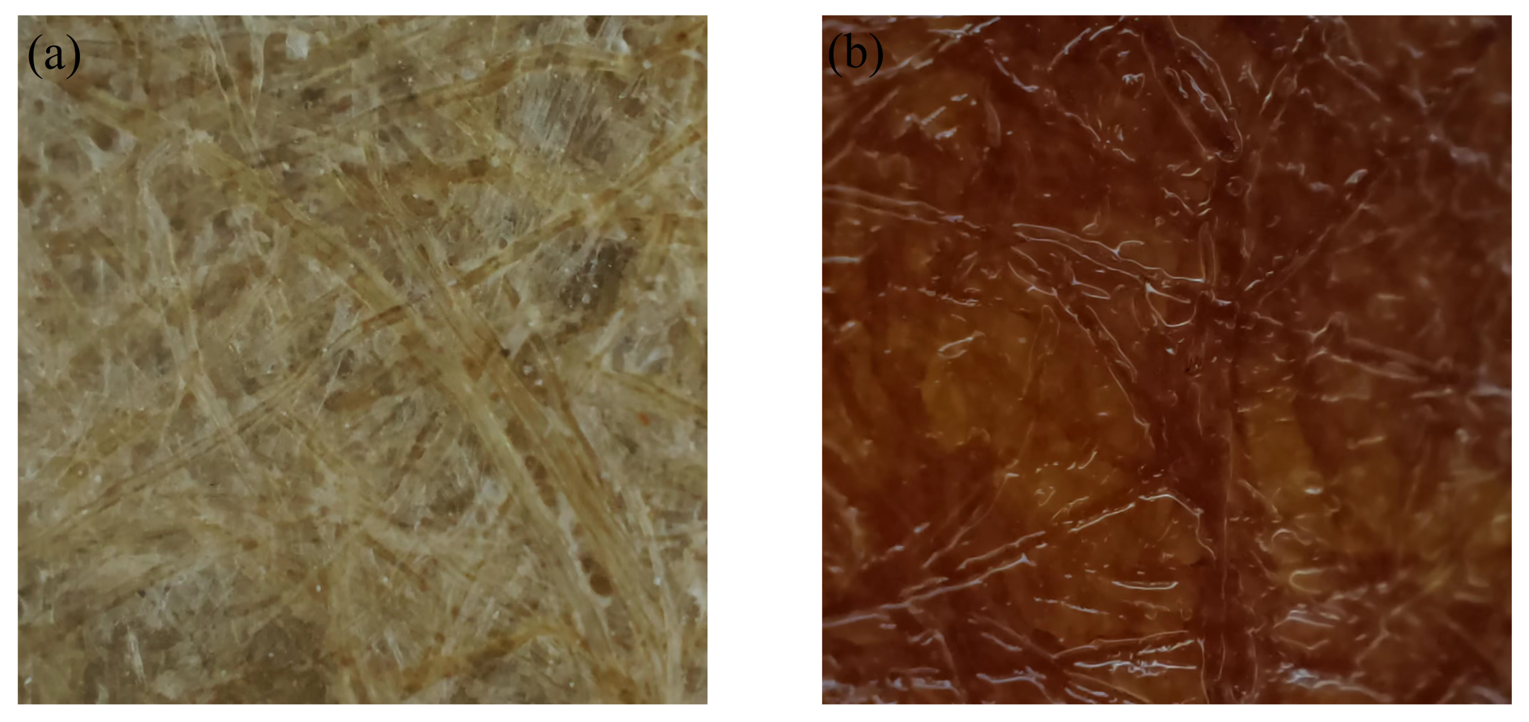
25]. Even after further calendering, the surface of the insulation paper still has a rough profile formed by interlaced fibre bundles. RMS surface roughness of insulation paper is observed at about 3∼7 μm, and fibre bundle width is 5∼50 μm. The porosity of the paper is called gas permeability. It is generally measured by the inverse of the paper’s air tightness. The permeability of winding insulation paper is generally 0.085∼0.225 μm/(Pa · S) [
26,
27]. The windings are made by bending paper-wrapped flat copper wires [
28]. The core and windings are immersed in a tank filled with transformer oil. Insulation paper has good oil absorption. Insulation oil compound molecules penetrate between the macromolecules of cellulose, causing capillary wetting and swelling in the cellulose structure. On the dry insulation paper surface, the fibre bundles are crisscrossed. After oil immersion, the insulation paper fibres absorb oil and swell. The paper’s surface appears to have large, rough contours, as shown in
Figure 1. The rough surface profile perturbs fluid flow within the two-dimensional boundary layer of the heat transfer surface, which has a more complex effect on the natural convective heat transfer efficiency [
16,
17,
29].
The flat copper wires generate Joules heating during operation, and the heat transfers to the outer surface of the insulation paper by penetrating through multiple layers of insulation paper [
30]. ONAN transformers rely primarily on the thermal convection of the oil to carry heat to the transformer shell, which in turn radiates heat to the surrounding environment. The oil temperature around the winding increases, resulting in a reduction in oil density. The buoyancy generated by the density difference makes the oil move upward in the vertical oil channel [
31,
32]. The fluid flow is driven by the buoyancy force only. Then, the heat exchange on the coupling surface is via natural convective heat transfer.
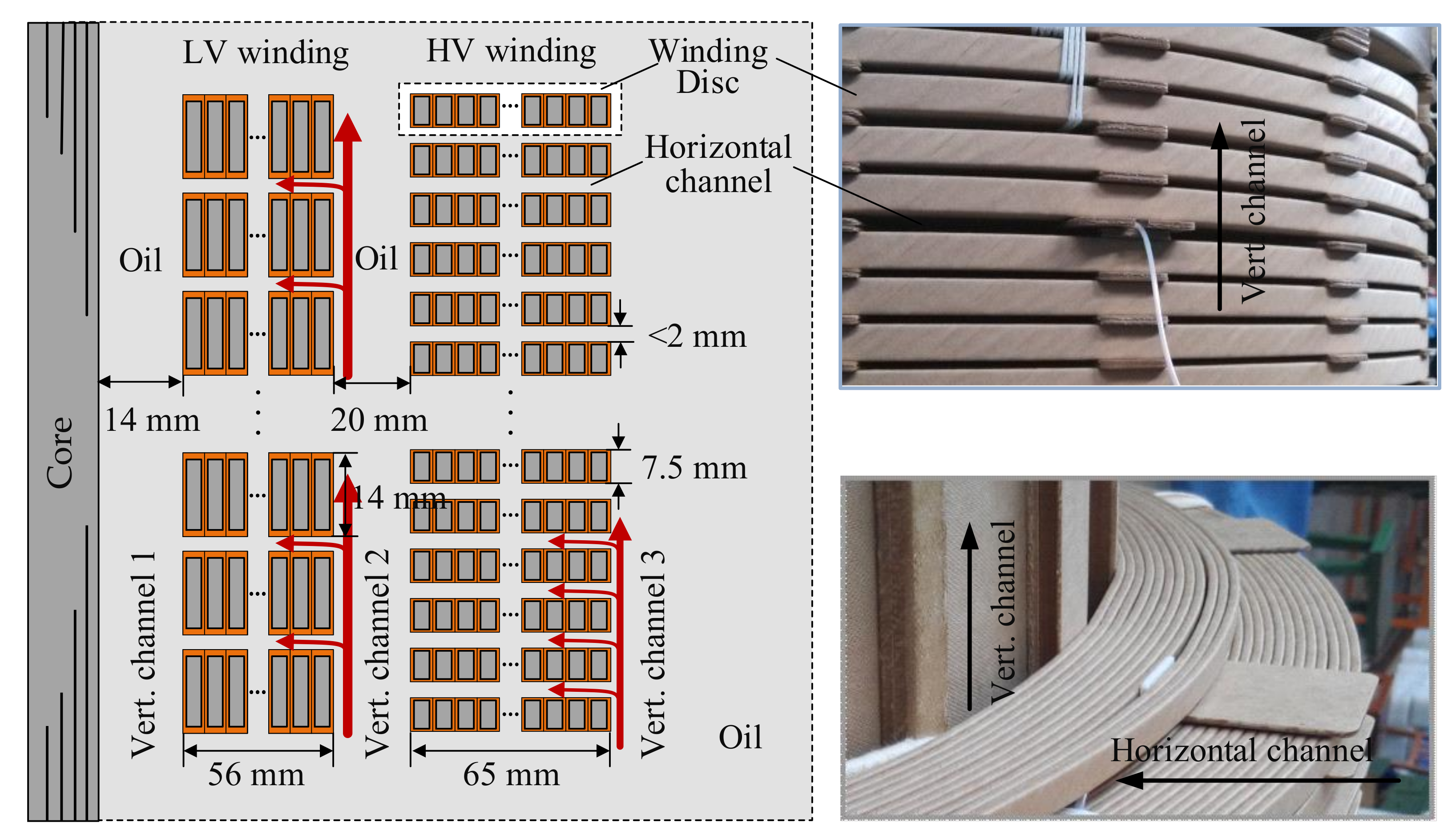
The ONAN transformer model SFZ11-10000 KVA/35 KV has high-voltage and low-voltage windings similar to concentric cylinders wrapped around a rectangular window in the iron core. The cooling system consists of a series of horizontal channels connected to two vertical oil channels. The internal oil channels are axisymmetric structures, and the length along the circumference is significantly longer than the radial width of the vertical oil channels. Thus, the heat transfer in the vertical oil channels is simplified as natural convective heat transfer between two vertical flat plates, as shown in
Figure 2. The heights of the high-voltage and low-voltage winding discs are 7.5 mm and 14 mm, respectively. The height of the horizontal oil channel between the discs is about 2 mm. The width of the vertical oil channel between the low-voltage winding and the iron core is 14 mm. The width of the vertical oil channel between the low-voltage winding and the high-voltage winding is 20 mm. The overall height of the winding is about 0.5 m. The contact area between the high- and low-voltage windings and the vertical oil channel is 3.137 m
2. Due to the narrow horizontal oil channel, the movement of transformer oil is restricted by the cavity, and the heat transfer of fluid in the interlayer mainly relies on heat conduction.
The insulation paper is sulfate wood pulp paper. The thermal conductivity
of insulation paper depends on the temperature, and the relationship can be expressed as
[
33]. The rough surface of the insulation paper has a particular influence on the flow pattern of the oil and has unique heat transfer characteristics. A total of 39% to 41% of the space inside the oil-immersed transformer is filled with Karamay
transformer cooling insulation oil. The
oil’s physical parameters are shown in
Table 1.
The oil temperature of ONAN transformers is affected by the winding temperature. The temperature field causes the oil density to change, resulting in a buoyancy force that acts as a driving force for movement rather than depending on external forces such as pump force [
34,
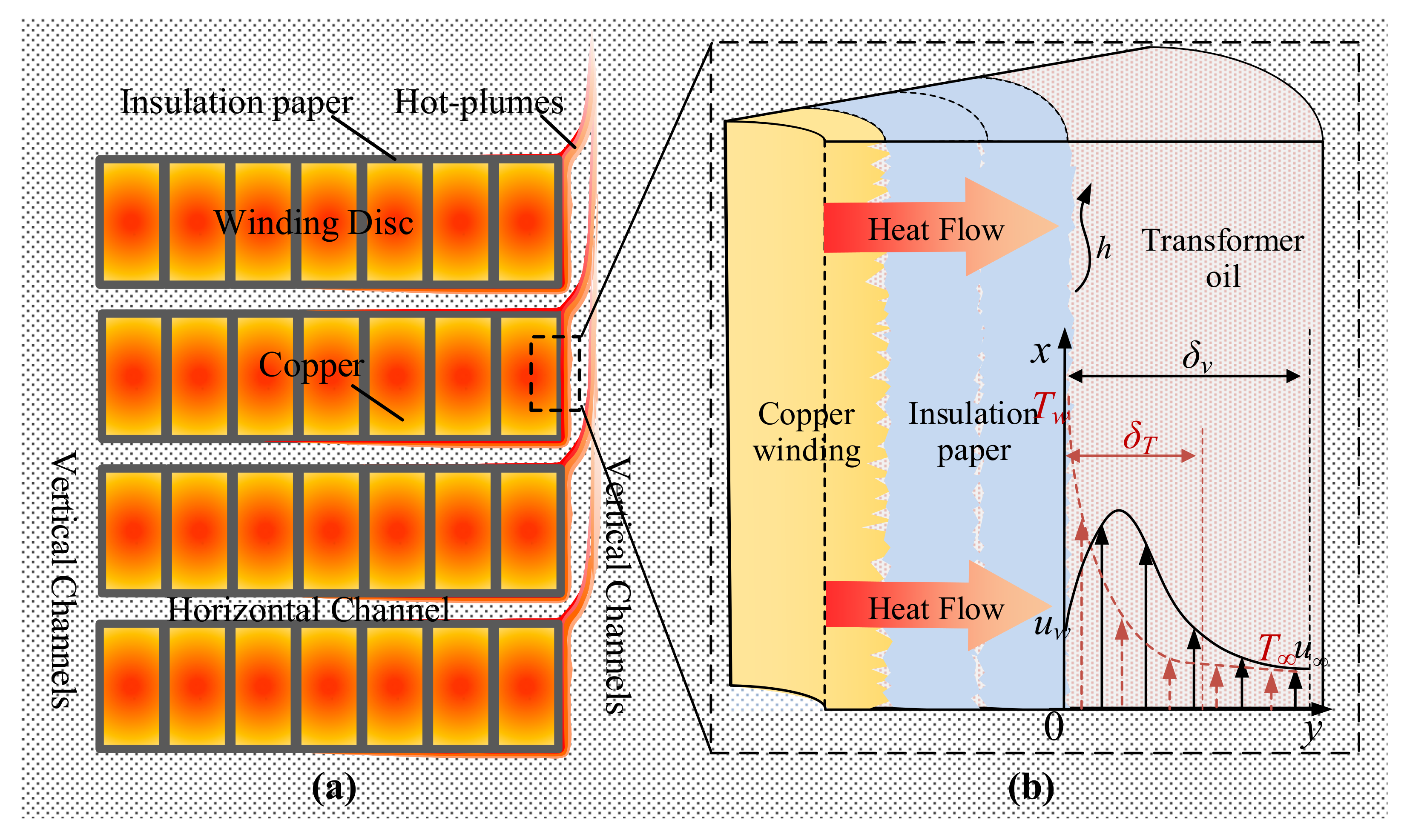
35]. The boundary layer is formed in the lower part of the winding disc. It separates from the upper edge under the interaction of viscous and floating forces. Furthermore, the boundary layer disintegrates at a certain distance in the vertical direction. The boundary layer of the unguided pancake winding is repeated this way, as shown in
Figure 3a. Fluids with large a Prandtl number cause hot plumes to form in the vertical oil channels because the lateral conduction of heat is slower than the vertical diffusion of momentum [
36]. The insulation oil in the vertical oil channel moves in a relatively large space. The thermal boundary layer in contact with the winding can fully develop without being disturbed, showing the flow characteristics of natural convection in a large space.
The convective boundary layer on the insulation paper surface for vertical oil channels is shown in
Figure 3b. The viscous effect causes the oil flow velocity on the insulation paper surface (
) to be zero, i.e., the oil satisfies the no-slip boundary condition on the insulation paper surface. As the viscous shear force gradually transmits to the outward normal direction of the vertical wall surface, the oil velocity quickly reaches the maximum value and then slowly decelerates to the mainstream velocity
[
37]. This area is the velocity boundary layer and has a thickness of
. Similarly, the heat is transferred from the vertical wall surface to the outward normal direction. The temperature gradually decreases from the vertical wall surface temperature
to the mainstream temperature
, and the area with a thickness of
where the oil temperature changes drastically is the thermal boundary layer [
38,
39]. The axial flow state of the transformer oil flow directly affects the heat transfer coefficient of the vertical wall surface of the disc.
The significant assumptions made in the paper are as follows: The velocity and thermal boundary layer are two-dimensional. The heat transfer process is steady state. The insulation oil is an incompressible Newtonian fluid with negligible density change. Insulation oil has no internal heat source and neglects radiative heat transfer. In addition, viscosity dissipation and volume forces are ignored. The heat transfer differential equation for the fluid flow is expressed as [
9,
22]:
Mass conservation equation
Energy conservation equation
Momentum conservation equation
By comparing the order of magnitude of each term in the control equation and discarding the term with the smaller order of magnitude, the control equation can be simplified. The order of magnitude of temperature
T is set to 1. The order of magnitude of the parameters in the x-direction is set to 1. In contrast, the order of magnitude in the y-direction is much smaller than 1 and is set to
δ. Therefore, in Equation (
2), the order of magnitude of
and
are (1/1)/1 and
, respectively;
is smaller and ignored, and the energy conservation equation is rewritten as
In Equations (
3a) and (
3b), the
y component of the momentum equation is smaller than the
x component, so Equation (
3b) is neglected. In Equation (
3a),
and
are of equal orders of magnitude, and both are 1. The order of magnitude of
is smaller than
;
is neglected. Moreover, the order of magnitude of
ν multiplied by orders of magnitude of
has to be 1 to satisfy this equation. The volume force of Equation (
3a) is
. Moreover, the pressure gradient along the vertical wall surface is caused by the height difference, i.e.,
. Thus the momentum equation (Equations (
3a) and (
3b)) in the natural convection boundary layer is rewritten as
Introducing the volume expansion coefficient
of insulation oil, the buoyancy term in Equation (
5) is expressed by the temperature difference. The vertical wall surface momentum equation of the natural convection boundary layer is
By dimensionless processing of Equation (
6), three dimensionless parameters,
Re, Grashof number (
Gr), and
Pr, are obtained to characterize the flow in the transformer cooling circuit.
Re indicates the ratio of inertial and viscous forces acting on a fluid.
Gr indicates the ratio of the product of inertial force and buoyancy force to the square of the viscous force.
indicates the temperature difference between the fluid and the vertical wall surface, i.e.,
. For natural convective heat transfer in an infinite space, the insulation oil is in laminar flow when the
Gr is between 1.4 × 10
4∼3 × 10
9, and the transition from laminar flow to turbulent flow happens when
Gr > 3 × 10
9 [
40].
Pr indicates the relative diffusion capacity of momentum and heat [
41]. The
Pr of Karamay 25
# transformer oil at 313.13 K is 126.5, and the thermal boundary layer is much thinner than the momentum boundary layer.
Nu represents the empirical correlation of the natural convective heat transfer coefficient of infinite space [
41,
42].
The physical properties of insulation oil are temperature-dependent. When calculating the dimensionless parameters in Equation (
10), the insulation oil temperature needs to be specified to determine the physical parameter. This temperature is the qualitative temperature
,
. Here
is the temperature of the insulation paper surface.
is the average value of the mainstream oil temperature, which is not affected by
, as shown in
Figure 3b. The characteristic length
l is the vertical wall surface height,
is the local surface heat transfer coefficient, and
λ is the thermal conductivity of insulation oil. Based on engineering experience, the
Gr is within 1.4 × 10
4∼3 × 10
9 when the insulation oil flow is laminar. The coefficient and index in Equation (
10) can be assigned
C = 0.59 and
n = 0.25, respectively.
As mentioned previously, the natural convective heat transfer coefficient is a complex function of various influencing factors, including surface roughness, which was not considered in the previous derivation. Intuitively, the rough profile on the vertical wall surface changes the direction of laminar flow. This results in increased surface fluid flow disorder and more adequate hot and cold fluid exchange, which is conducive to natural convective heat transfer. However, the heat transfer coefficient is an empirical value, and it is not easy to give a definite formula to calculate the natural convective heat transfer coefficient from theory. It is advisable to set the correction factor ε of the natural convective heat transfer coefficient due to roughness and oil viscosity, express the characteristic number equation as , and fit the correction factor by experimental methods.
3. Similarity Principle and Modelling Test
Estimating the natural convective heat transfer coefficient utilizing the experimental correlation equation for natural convection can only obtain an approximate range. The experimental method is still the most direct way to determine the coefficient. The shape and location of the heat transfer surface, thermal boundary layer conditions, and different flow regimes affect the values of
C and
n. Two heat transfer phenomena are similar if the independent characteristic numbers of the two phenomena are equal and their singularity conditions are similar [
42]. Modelling experiments utilize models different from the actual geometric scale to study the physical processes carried out in practical devices. The approximate modelling method requires that the physical phenomena carried out in the practical device and the model, as well as the conditions that have a decisive influence on the process, satisfy the similarity principle [
43]. The actual conditions such as the microscopic morphology of the insulation paper surface, the microscopic flow of oil, and the oil–paper contact surface are simulated by modelling experiments.
The Pipe insulation apparatus is an experimental apparatus specified in ISO 8497:1997 for determining a thermal insulation’s steady-state heat transfer properties [
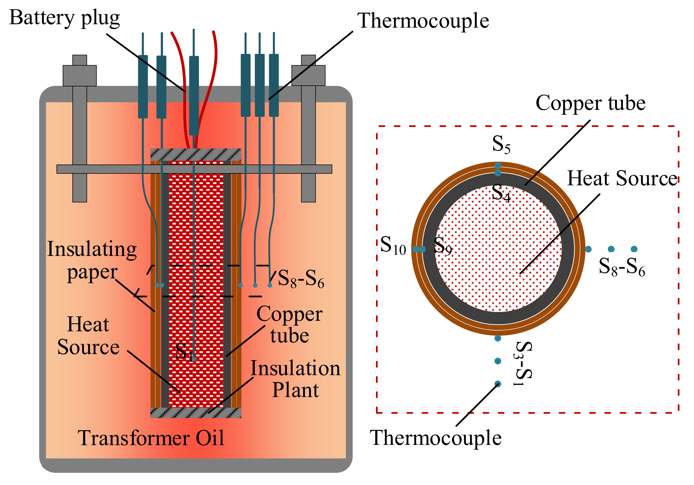
44]. It can determine a variety of thermophysical properties of solid materials. Based on this apparatus, an experimental apparatus for determining the natural convective heat transfer coefficient of the insulation paper–oil contact surface has been constructed, as shown in
Figure 4. The circular copper tube is made of the same material as the transformer winding magnet wire. The outside of the tube is wrapped flat and tightly with two layers of insulation paper. The insulation paper is selected and wrapped the same way as the transformer winding. An electric heating rod is inserted into the circular copper tube as a stable heating device to simulate the heat generated by the winding magnet wire. The micro gap between the copper tube and the heating rod is filled with high-thermal-conductivity silicone grease. The uniformity of the radial heat flow through the purple copper tube is improved. The upper and lower ends of the copper tube are sealed with thermal insulation gaskets and asbestos mesh to prevent heat dissipation in the longitudinal direction. The above device is installed in a closed stainless steel tank filled with Karamay 25
# oil. When heated, the heat flow penetrates the insulation paper and transfers to the surface of the outer insulation paper. The oil in contact with the insulation paper carries the heat away; the process is consistent with the winding heat transfer shown in
Figure 3. The natural convective heat transfer phenomenon can also be described by Newton’s cooling law.
where
Q is the power of the electric heating rod and
A is the heat transfer area.
. From another perspective, the large-space natural-convection experimental correlation equation can express the natural convective heat transfer coefficient. Thus, the local surface heat transfer coefficient
can be expressed as
Calculating the natural convective heat transfer coefficient boils down to obtaining the temperature of the fluid on the vertical wall surface. Thermocouples are utilized to measure the oil temperature gradient and the temperature on both sides of the insulation paper. The bare bead thermocouple (model WRNK-191K) is made of insulated thermocouple wire. The bare bead diameter is 0.5 mm, the measurement range is 273.13∼1373.13 K, and the accuracy is 0.4%
T. In order to investigate the influence of the two-dimensional boundary layer developmental state on natural convective heat transfer, temperatures are measured at the middle section and lower section of the vertical tube. As illustrated in
Figure 4, ten thermocouples are installed at two heights. S1∼S5 are 3 cm from the bottom end of the vertical tube. S6∼S10 are 6 cm from the bottom end. S3 is tightly attached to the surface of the insulation paper. S1, S2, and S3 are spaced at 2 mm. S4 is between two layers of insulation paper, and S5 is between the inner layer of insulation paper and the copper tube. The thermocouples in the round tube’s middle section are installed similarly.
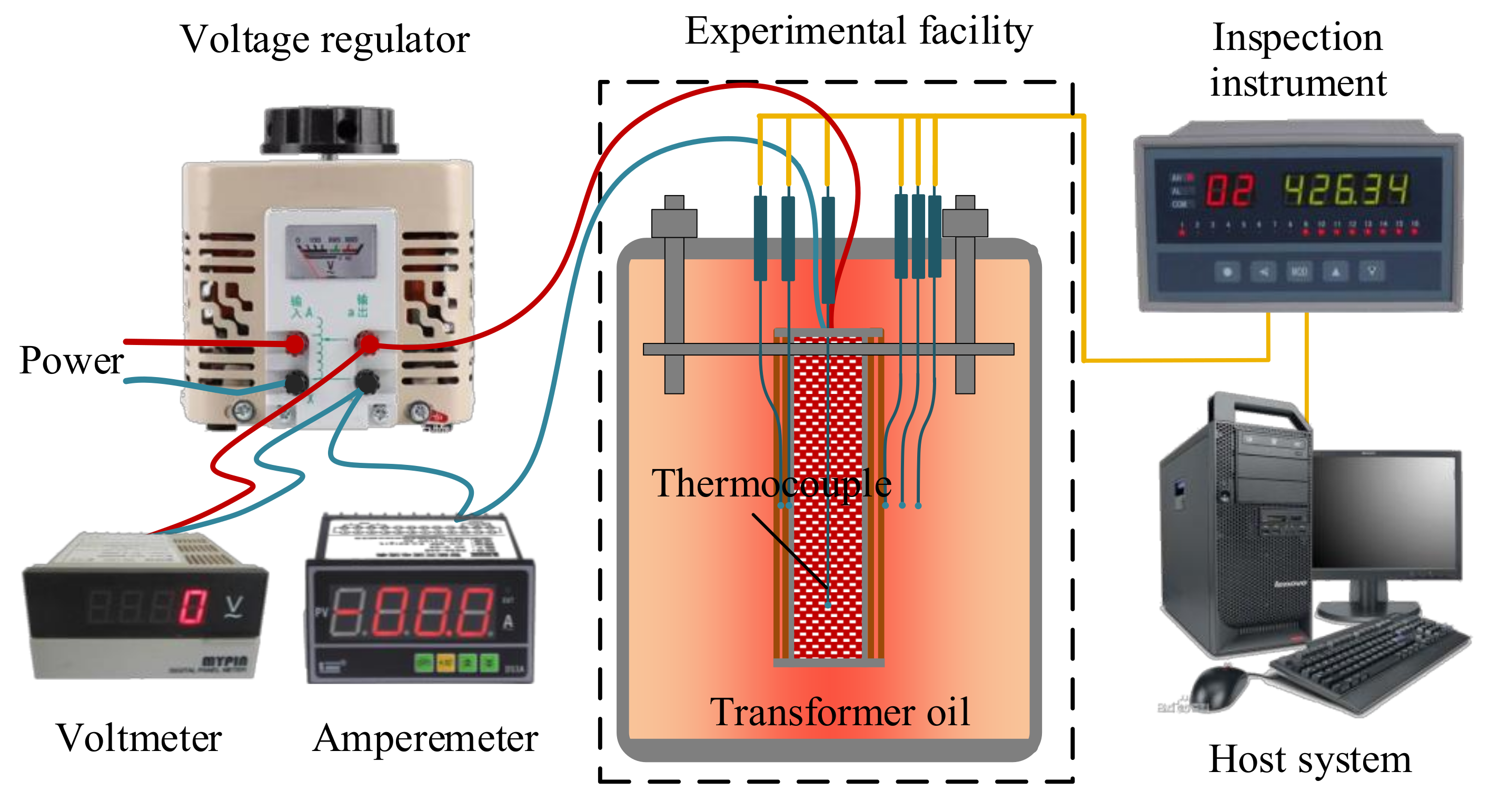
The stainless-steel tank and internal device are placed in a temperature and humidity programmable chamber. The internal temperature of the chamber is set at 295.15 K to reduce experimental errors caused by fluctuations in ambient temperature. A single-phase voltage regulator (model UTP3313TFL-II) provides a variable stable voltage to adjust the heating power. A digital voltmeter (model DS3A-DA2) and digital amperemeter (model MDH8-1A) record the heating power. Temperature loggers (model KCM-XJ16WRS) read the thermocouple temperature and upload the values to the host computer. The schematic diagram of the experimental platform is shown in
Figure 5.
Turn on the single-phase voltage regulator to output a specific stable power to heat the copper tube. When the values of the thermocouple change by less than 0.2 K over half an hour, heat generation and transfer have reached dynamic equilibrium. The computer records two sets of temperature data every minute, and each test records 100 sets of data. After one experiment, wait for the device to cool to ambient temperature and then carry out another experiment.
4. Results and Discussion
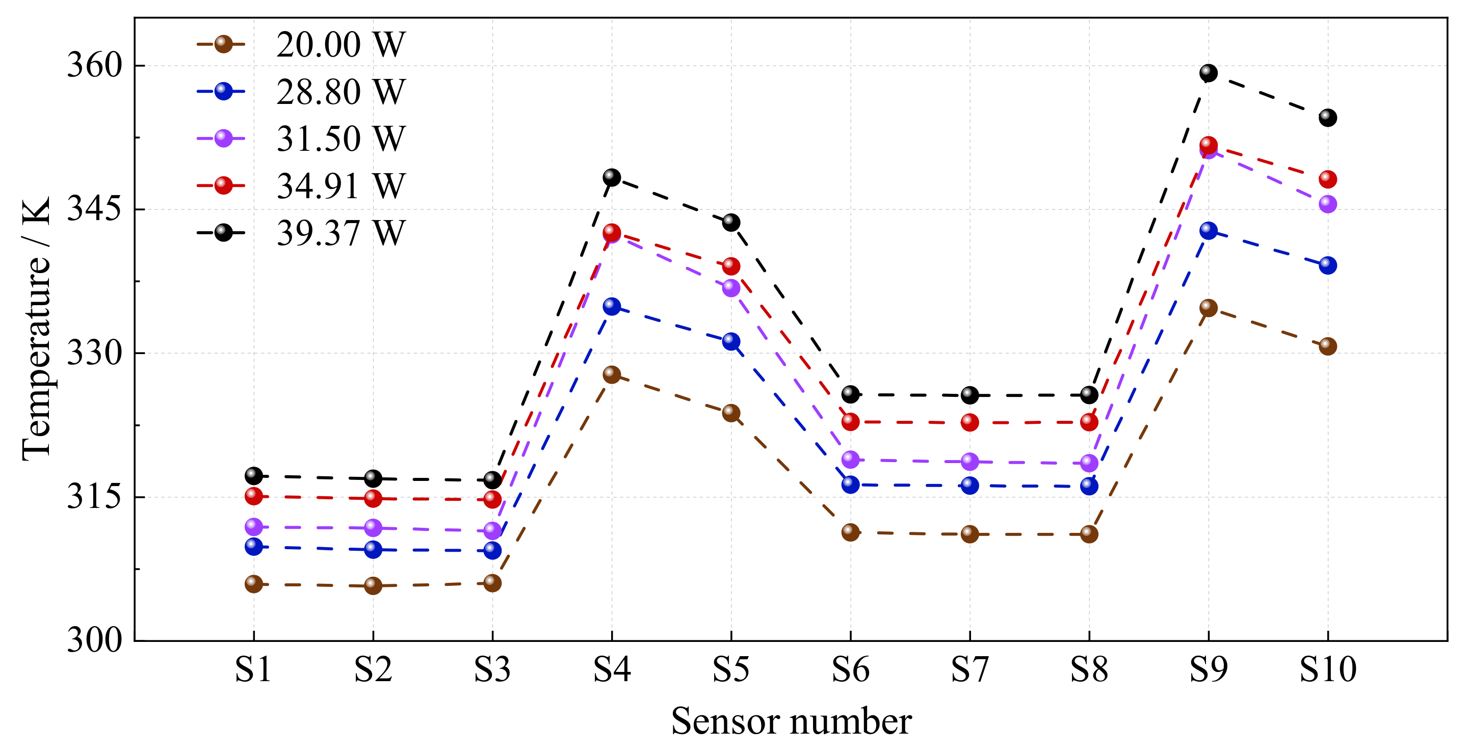
This paper conducted tests at five powers of 20.00 W, 28.80 W, 31.50 W, 34.91 W, and 39.37 W. The thermocouples measured the temperature distribution of the insulation paper and oil, as shown in
Figure 6. It can be seen that the temperature of S6∼S10 is higher than that of S1∼S5 at the corresponding position because the hot oil flows upwards. The upstream heat flow influences the natural convective heat transfer characteristics at the downstream position, which confirms that
Nu and
Gr are closely related to the characteristic length
l. S1∼S3 and S6∼S8 have the same temperature gradient, which is almost zero. This shows that the temperature boundary layer on the insulation paper surface is so thin that even a 0.5 mm temperature probe mounted against the wall lies outside the temperature boundary layer. Furthermore, the mainstream temperature
outside the boundary layer is not influenced by the natural convective heat transfer on the surface. Due to the thermal resistance of the insulation paper, there is a temperature difference between S4 and S5. Combined with the local temperature, the thermal resistance of the insulation paper on the outside of S5 can be obtained by Fourier’s law of thermal conductivity. Therefore, the temperature of the outer surface for the outermost insulation paper can be obtained, i.e.,
in
Figure 3b.
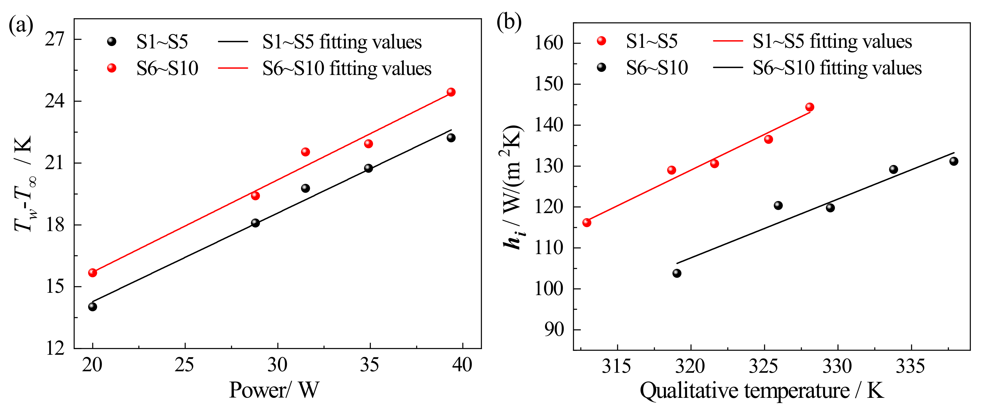
The temperature difference
in Newton’s cooling formula and
Gr is taken as
, as shown in
Figure 7a. The
increases approximately linearly with the increase in power. The thickness of the boundary layer increases with height during laminar flow, and the thermal resistance of laminar heat transfer increases, resulting in a greater
in the middle section (S6∼S10) of the vertical tube than
in the lower part of the vertical tube (S1∼S5). Assuming that the copper tube has no axial heat dissipation, the heat transferred radially by the tube per unit of time is approximately the power given by the single-phase voltage regulator. According to the experimental data and Newton’s law of cooling in Equation (
11), the natural convective heat transfer coefficient under different qualitative temperatures
can be obtained, as shown in
Figure 7b. The middle section’s coefficient is smaller than that in the lower part of the vertical tube due to the difference in characteristic length. The natural convective heat transfer coefficient linearly increases with the increase in qualitative temperature. The linear relationship is obtained by the least square fitting method, and the R
2 values of of S1∼S5 and S6∼S10 are 0.973 and 0.928, respectively.
The qualitative temperature in the experiment is substituted into the oil physical property function in
Table 1, and the
gr and
Pr are calculated by combining the installation height of the thermocouple, i.e., the characteristic dimension
l. The
Gr and
Pr are shown in
Table 2. The
Gr is within 1.4 × 10
4∼3 × 10
9, so the flow regime of the insulation oil is laminar, and the coefficient
C and exponent
n in the characteristic number equation are 0.59 and 0.25, respectively. The natural convective heat transfer coefficient is solved according to Equation (
10). For comparison, the heat transfer coefficients obtained from Newton’s law of cooling are listed together.
As shown in
Table 2, the natural convective heat transfer coefficients calculated with the characteristic number equation are smaller than those calculated with Newton’s law of cooling. The deviation in the vertical tube’s lower part is less than 8.48%. In the middle section of the vertical tube, the deviation is less than 11.83%. The more fully the insulation oil flow state is developed, the larger the resulting deviation is. Such deviations are acceptable for general engineering calculations. Further, the uncertainty may be related to the following aspects. Insulation oil is composed of various compounds, and typical values of physical parameters differ from the actual experimental conditions. The coefficients calculated by Newton’s cooling equation depend on the power and temperature measurements’ accuracy. The characteristic number equation relates to the accuracy of the characteristic dimensions and qualitative temperature measurements.
The axial leakage heat of the heating tube is much smaller than the total heating amount, so the deviation of the heat flow per unit length is negligible. The measurement deviation of the outer diameter of the copper tube is much smaller than that of the outer diameter, and the calculated deviation of the heat transfer area is negligible. The measurement uncertainty mainly comes from the power measurement deviation and the temperature measurement deviation. The uncertainty of power measurement is related to digital multimeter fluctuation. The resolution of the temperature inspection instrument in the data acquisition unit is 0.1 K. The measurement accuracies of the digital voltmeter and digital amperemeter are ±0.5% F.S. ±2 digit and ±0.2% F.S. ±2 digit, respectively. The measurement accuracy of the thermocouple is 0.4%
T, and the maximum measurement error is 0.34 K in this experiment. The uncertainties are calculated by
where
is the measurement error of
y, which is a function of
, and
is the maximum measurement error of each variable
. The maximum uncertainties are 0.8% for the power and 2.34% for the temperature difference.
Since the empirical values are somewhat universal, the accuracy of the solution is low for specific cases, such as complex structures of transformer windings and insulation paper with a certain roughness. The experimental data were fitted by empirical parameters, i.e.,
C = 0.59 and
n = 0.25, with a fit of 77.26%. A non-linear fit to the experimental natural convective heat transfer coefficient is based on the mathematical form of the characteristic number equation Equation (
10). As the curve of the fitting function gradually approaches the scatter point of experimental data,
and
n = 0.25, the degree of fitting is 88.91%. We compare the natural convection heat transfer coefficients calculated based on empirical parameters and parameter optimization with experimental data. The maximum and average deviations before correction are 11.83% and 6.39%. The maximum and average deviations after correction are 5.93% and 3.06%, as shown in
Table 3. With the optimized parameters, the natural convective heat transfer coefficient is closer to the solution result of Newton’s cooling law.
For transformer model SFZ11-10000 KVA/35 KV and other ONAN transformers, the main factors affecting the natural convection heat transfer are the thermal and kinematic properties of the fluid within the two-dimensional boundary layer. The characteristic number equation derived from the control equation gives a good overview of its thermal characteristics. However, the exact calculation process depends on the geometry of the heat transfer surface and the surface condition (rough or smooth). The rough surface formed by the expansion of the fibre bundle of the insulation paper has a specific influence on the flow state of the boundary layer. The same insulation paper was used for the modelling experiments based on similarity principles, and the surface micromorphology was incorporated into the analysis of the experimental data. The experimental data were fitted with the mathematical form of the characteristic number equation to obtain the coefficients to be determined in the characteristic number equation and obtain the correction factor for the microform influence.


