Review

Processing and Advancements in the Development of Thermal Barrier Coatings: A Review

1
Department of Mechanical Engineering, DAV University, Jalandhar 144012, India
2
School of Mechanical Engineering, Lovely Professional University, Phagwara 144411, India
3
Division of Research and Development, Lovely Professional University, Phagwara 144411, India
4
Department of Mechanical Engineering, GLA University, Mathura 281406, India
5
Department of Mechanics and Strength of Materials, Politehnica University Timisoara, 1 Mihai Viteazu Avenue, 300 222 Timisoara, Romania
6
Division of Research & Innovation, Uttaranchal University, Dehradun 248007, India
7
State Key Laboratory of Mechanical System and Vibration, School of Mechanical Engineering, Shanghai Jiao Tong University, Shanghai 200240, China
*
Authors to whom correspondence should be addressed.
Coatings 2022, 12(9), 1318; https://doi.org/10.3390/coatings12091318
Submission received: 15 August 2022 / Revised: 30 August 2022 / Accepted: 31 August 2022 / Published: 9 September 2022
(This article belongs to the Special Issue Energy, Material Science and Environmental Engineering)

Abstract

:
Thermal barrier coating is critical for thermal insulation technology, making the underlying base metal capable of operating at a melting temperature of 1150 °C. By increasing the temperature of incoming gases, engineers can improve the thermal and mechanical performance of gas turbine blades and the piston cylinder arrangement. Recent developments in the field of thermal barrier coatings (TBCs) have made this material suitable for use in a variety of fields, including the aerospace and diesel engine industries. Changes in the turbine blade microstructure brought on by its operating environment determine how long and reliable it will be. In addition, the effectiveness of multi-layer, composite and functionally graded coatings depends heavily on the deposition procedures used to create them. This research aims to clarify the connection between workplace conditions, coating morphology and application methods. This article presents a high-level overview of the many coating processes and design procedures employed for TBCs to enhance the coating’s surface quality. To that end, this review is primarily concerned with the cultivation, processing and characteristics of engineered TBCs that have aided in the creation of specialized coatings for use in industrial settings.

1. Introduction

This study’s main objective is to reduce carbon dioxide emissions from the atmosphere and meet the population’s energy demand without harming the climate. A gas turbine can operate at a higher temperature and achieve maximum work output, with minimum energy loss. The advanced gas turbine engine will work in modern times using renewable or non-renewable energy resources for industrial applications, such as producing electricity and operating for the aerospace engine. With the aid of thermal barrier coating in this field, the market area is expected to reach USD 30.7 billion by 2025. Various researchers have found that gas turbine engine modification improves the superior turbine blade efficiency [1]. Technological improvement in gas turbines plays a vital role in filling rising energy requirements and reducing the carbon dioxide emission rate. The challenge facing gas turbines is to prevent their working parts from degradation, as the turbine works at a higher temperature and a corrosive environment [2]. The steam turbine engine’s work quality depends on a higher gas inlet temperature and reduced energy loss during turbine blade operation. The combustion chamber’s temperature is maintained inside by using the turbine component’s insulation with the surface coating process’s help, preventing the turbine component from degradation. Sometimes, the working temperature of steam turbine blades is above the range of melting temperature of the base metal, and overcoming this problem is to use a suitable coating method. By efficiently supplying internal air cooling, the substrate material’s surface temperature can be reduced up to 300 °C [3]. TBCs have been developed to insulate the substrate material’s surface layer and prevent thermal shocks and corrosive environmental conditions during work. The thermal spray process is widely used for coating the gas turbine component because it can coat intricate shapes. TBC can also affect several factors, such as heat flux, heat transfer coefficients, coating thickness, and thermal conductivity, to define the substrate’s magnitude of temperature decrease. These constant efforts to increase a gas turbine engine’s efficiency have resulted in working temperatures to over 1300 °C, which requires thicker TBCs with their chemistry development, including the newly cooling system [4]. If the topcoat thickness increases, the substrate coating components’ surface temperature decreases from 4–9 °C per 25 μm and avoids surface coat failure under higher-temperature oxidation conditions [5]. The thermal stability of the turbine components at higher temperature thermal shock resistance and wear resistance using conventional or nanostructured coating methods is also helpful for coating the complex shape components for gas turbines or diesel engines. Increased steam turbine engines’ efficiency eventually provides practical assistance in aircraft performance and fuel efficiency and supports them in carrying increased payloads. The gas turbine engine produces the maximum amount of mechanical work output for low wastage of thermal energy in land-based applications. It helps generate electricity in thermal power stations. Figure 1 shows that the compressor sucked the air from the environment, then compressed that at a higher pressure; after this, it delivers this air into the combustion chamber, where it helps for burning the all-fuel particles that help for generating the higher amount of heat energy inside the combustion chamber and reduce the wastage of unburned fuel particles. The turbine inlet temperature is similar to the combustor outlet temperature and turbine blades are used to convert the heat into mechanical energy by revolving them into high speed [6].
The thermal efficiency (η) of a gas turbine following an ideal Carnot cycle [7]:
η = 1 − (Texit/Tinlet)
where, Texit = represent the exit temperature of the gas, Tinlet = represent the inlet temperature of the gas.
Equation (1) shows that increasing the gas turbine’s inlet temperature can improve its thermal efficiency [7]. Raising the turbine’s inlet temperature sets an immediate requirement on the materials working in the gas turbine’s hot regions, where the temperatures approximate the range of 1500 °C [8]. Here, the temperature is higher than the melting point of the most reliable working materials in gas turbines now, such as nickel-based superalloys. When rising the temperature of hot gas inside the turbine inlet, it is more important to control the temperature and protect the turbine component from degradation. Hence, it is feasible to use outside insulation of the surface material and an internal cooling system for turbine components. This internal cooling system is used to restrict the volume of air and control the heating temperature without decreasing the gas turbine’s thermal efficiency. When a quantity of air higher than 8% is utilized for cooling purposes for the turbine, the main benefit of this cooling system is to regulate the working temperature and increase the mechanical and thermal efficiency of turbine blades [8]. Coating quality advancements can improve work performance and reliability [9]. The researchers’ foremost challenge issues in surface coating are how to improve the thermal stability of the ceramic powder material at a higher working temperature to provide a better insulation property for the substrate metal [10]. The various approaches and synthesis mechanisms can be used for materials processing in other applications [11]. The details of papers published on thermal barrier coatings have been fetched from scopus.com (accessed on 23 August 2022) and presented in Figure 2. Researchers are focusing on the challenges associated with thermal barrier coatings, and advancements are still going on in this field.
TBCs are used to insulate gas turbine components that are subjected to excessive temperatures. Since low thermal conductivity allows these coatings to act as thermal barriers, metal surface temperatures decrease. Lower metal temperatures are given greater component durability by reducing creep stress and fatigue, while also reducing oxidation and corrosion rates. Advances are going on in the field of high-temperature applications. Materials that can sustain high temperatures need to be optimized. Thermal barrier coatings need optimization in terms of resisting high temperature oxidation, erosion and hot corrosion. This paper emphasizes the recent techniques used in the development of thermal barrier coatings and their performance has been analyzed. The authors have incorporated the need for this review article into the revised manuscript.

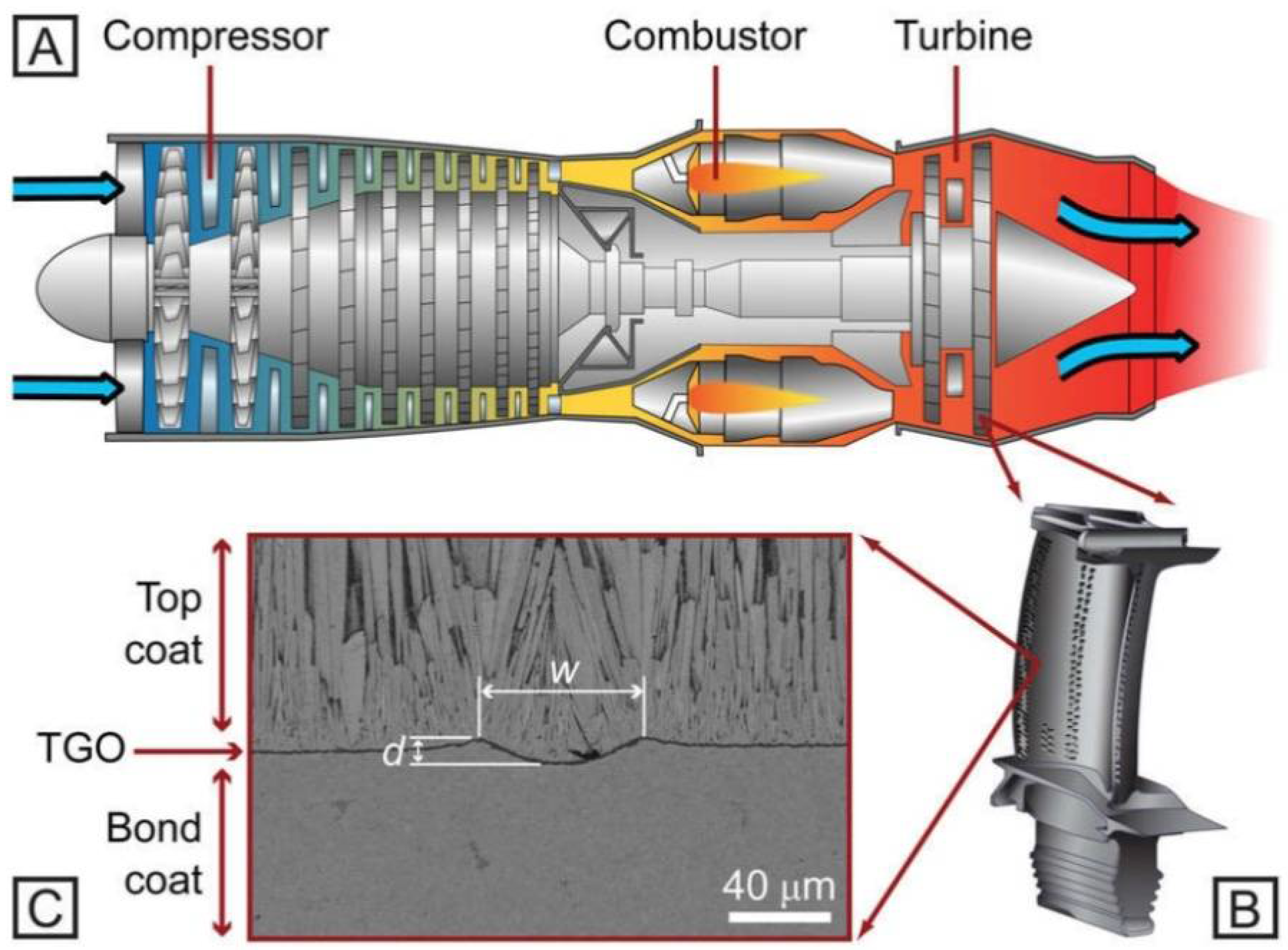
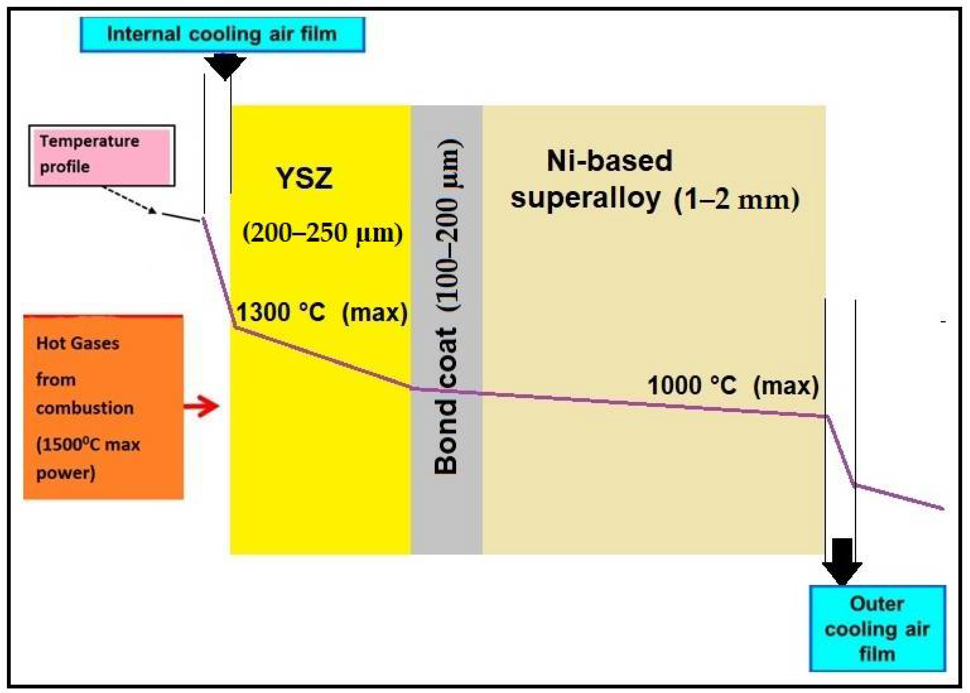
2. Thermal Barrier Coating System

TBCs are coated processes used for intricate surface material systems that are useful for gas turbine engines implemented in hot regions. This multi-layered coated surface has a formation where the top coating layer comprises a lower thermal conductivity ceramic and thermal insulation from hot burning gases [12]. The schematic is shown in Figure 3. At maximum engine power, the modern turbine inlet temperature (TIT) of state-of-the-art jet plane turbines reaches a value of approximately 1500 °C. The component temperature level is higher than the maximum operating temperature of YSZ TBCs, which is around 1300 °C. Underneath the topcoat is a bond coat that contributes a vital role for bonding effect between the ceramic material and base metal for protecting turbine components against oxidation and corrosion effect at high temperatures and crossover working environment.
Figure 4 shows the SEM images of a polished cross-section of traditional as-sprayed and nanostructured TBCs, which constituted the YSZ topcoat and the NiCoCrAlY bond coat collected by the APS process on the superalloy substrate metal. After the solidification process was completed for the partially molten and completely molten powder grains, the conventional and nanostructured YSZ covered layered form. Micropores can be seen in the cross-section of the YSZ coating in both layers, as well as on the coating’s outer surface. Nevertheless, in the nanostructured coating produced from very fine grains, the inhomogeneities and micropores are frequently decreased, most likely due to the compactness of the nanostructure [13].

2.1. Material in a TBC System
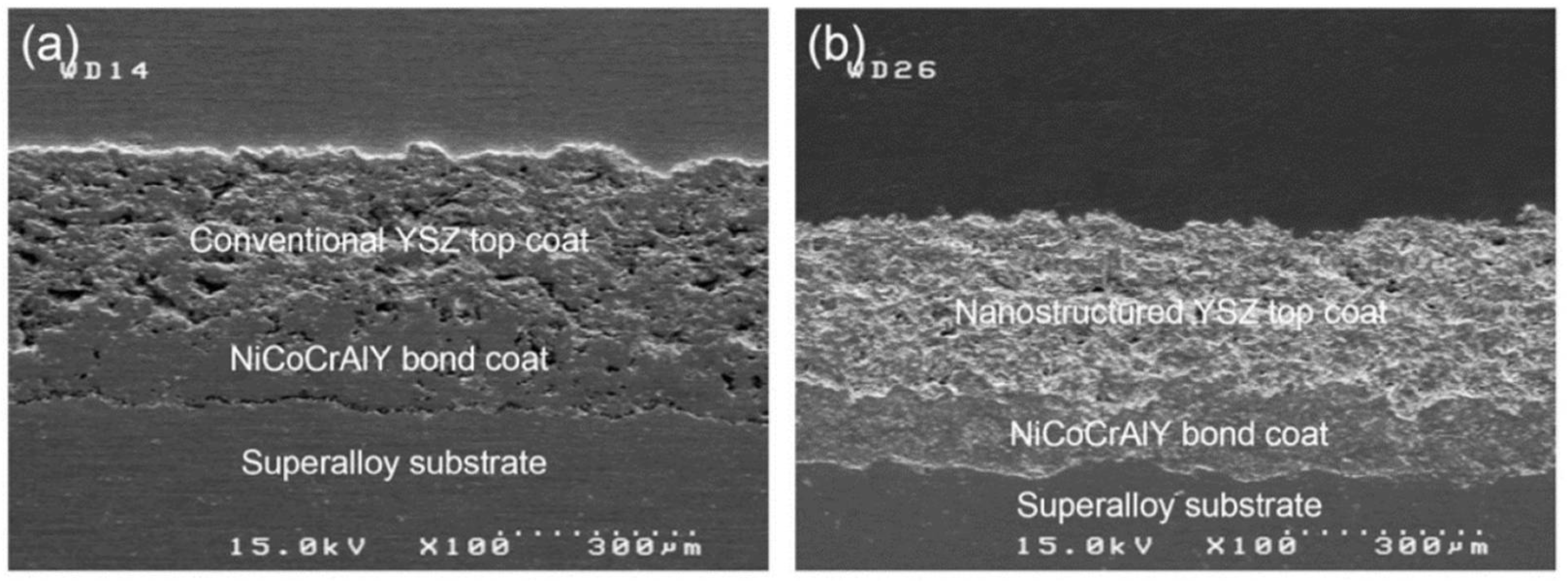
2.1.1. TopCoat

The thermal spray coatings’ upper zone contributes heat resistance against the burning gases into a gas turbine engine’s combustion chamber. The durability and topcoat performance are increased by providing an internal cooling system that keeps the base metal’s heating temperature lower, which is why it does not decrease its load-bearing ability. This heating temperature can decrease from 150–250 °C in the upper layer topcoat, depending upon the coated layer’s thickness and the type of ceramic grain size [13]. The ceramic powder materials have been investigated for insulation purposes for gas turbine blades by a thermal spray coating process used to improve the thermal stability of the topcoat materials. Yttria-stabilized zirconia (YSZ) powder was mainly used for industrial application because it provided better thermal stability. YSZ ceramic powder particles need to have many required characteristics for the working heat limit, such as increased melting point temperature, reduced thermal conductivity, and improved phase stability [14].
The lower coefficient of thermal expansion is a significant factor in the improved life of coated surface material controlled by proper coating methods. A single ceramic material can be challenging to fulfil all of the coated ceramic materials’ conditions, using a mixture of two or more ceramic materials to overcome these situations. In addition to yttria-stabilized zirconia in the range of 6–8 wt.%, this gives the topcoat powder grains better performance because of its comparatively lower density, lower thermal conductivity and higher concentration for point defects [15]. Many researchers want to develop the YSZ coating structure’s excellent quality, which improves the components’ durability and reliability at a higher working temperature [16]. In the opposite direction, YSZ already has a few drawbacks for coating utilization, such as reduced working temperature less than 1200 °C, susceptibility to thermal corrosion, impressive atmospheric sediments, and stimulated thermally grown oxide generation large diffusivity of ionic oxygen in ceramics based on ZrO2 [17].
Hence, it is essential to improve the coating material’s work performance and provide a more stable coating microstructure. To prevent the substrate metal from deteriorating at higher temperatures and corrosive environmental conditions. The 8YSZ/graphite powder material is used for high-temperature applications. It has good insulation properties that protect substrate metals by reducing the heat transfer rate between the coating and substrate surfaces [18]. At present, various researchers have worked to produce agglomerated nanostructurednanostructured8 wt.% YSZ powder grains that can be used for the thermal spray coating process. The size range of conventional powder grains varies from 10 to 100 μm, but on the other hand, the size range of nanostructured powder grains varies from 40 to 50 nm. In the thermal spraying process YSZ, nano-clusters use feedstock to control the supply of powder grains during the working process. The nano-clusters agglomerate powder grains during spray drying, which can help obtain micro-sized particles for TBC coating [19]. The coating quality relates to the complete molten for the powder grains before being deposited on the base material in the thermal spray process. The chemical reaction technique plays a significant role in manufacturing nanostructured powder grains and makes them capable of surface coating. The spray-drying method is an essential and valuable technique for agglomerating nanostructured powder grains. This technique helps protect them from overheating before depositing onto the substrate material [20]. The various kinds of powder grains material utilized in combining multi-layered topcoat structured ceramics could be a successful option.

2.1.2. Bond Coat

Many scientists have improved the bond strength obtained from nanostructured powder grains. As a bond coat below a ceramic topcoat in TBC systems, MCrAlY has been commonly employed. By practising standard C633-01, the shift from the bond coat hardness is proposed to occur guided by this adhesive force when that breakdown occurs from the bond-coated base metal in this interface. That cohesive force fracture is entirely within this coated layer [21]. Consequently, this bonding of the power inside the associated splitting is stronger than that without splitting. It is well understood that combining governs the adhesive strength of the situation within sprinkling materials, including the base material. The YSZ-based coating material manages residual tension from the base material’s coated form [22]. This kind of residual stress is made from a couple of parts in that sprayed method, such as quenched stress that produces reduction for the various splats and cooled pressure generated by the unmatched heat extension between that deposited on the base material while all collectively cooled later deposited [23]. One of the promising ultra-high-temperature applicant metals for a material bond coat is the intermetallic composite NiAl, which has a higher molten point (1638 °C), lower density (5.9 g/cm3), relatively greater elastic modulus (240 GPa), and excellent oxidation protection at 1200 °C [24]. On the other hand, the functional utilization of NiAl under a higher-temperature environment is restricted by its brittleness, low adhesion strength within this oxidation film, and base metal. This diffusion process occurs between the Ni and Al atoms because a higher temperature operation toward the model also limits the powder grain characterization of NiAl [25,26]. After performing the experiments, it was observed that the more outstanding durability of bonding from the nanostructured coating was determined by the greater internal toughness achieved [27,28]. As this conventional coated approach watched some inner face inside this powder material, some kept fully melted into the spray blast, and this base metal showed minor cracks. As this nanostructured coated, some interfaces inside this powder grain were partially melted during this spraying process. Adherents in the coating occurred in this base metal. Thus, interface cracks within the nanostructured-coated structure are prevented. The firm-adherent compact nanostructure increases the bond strength.

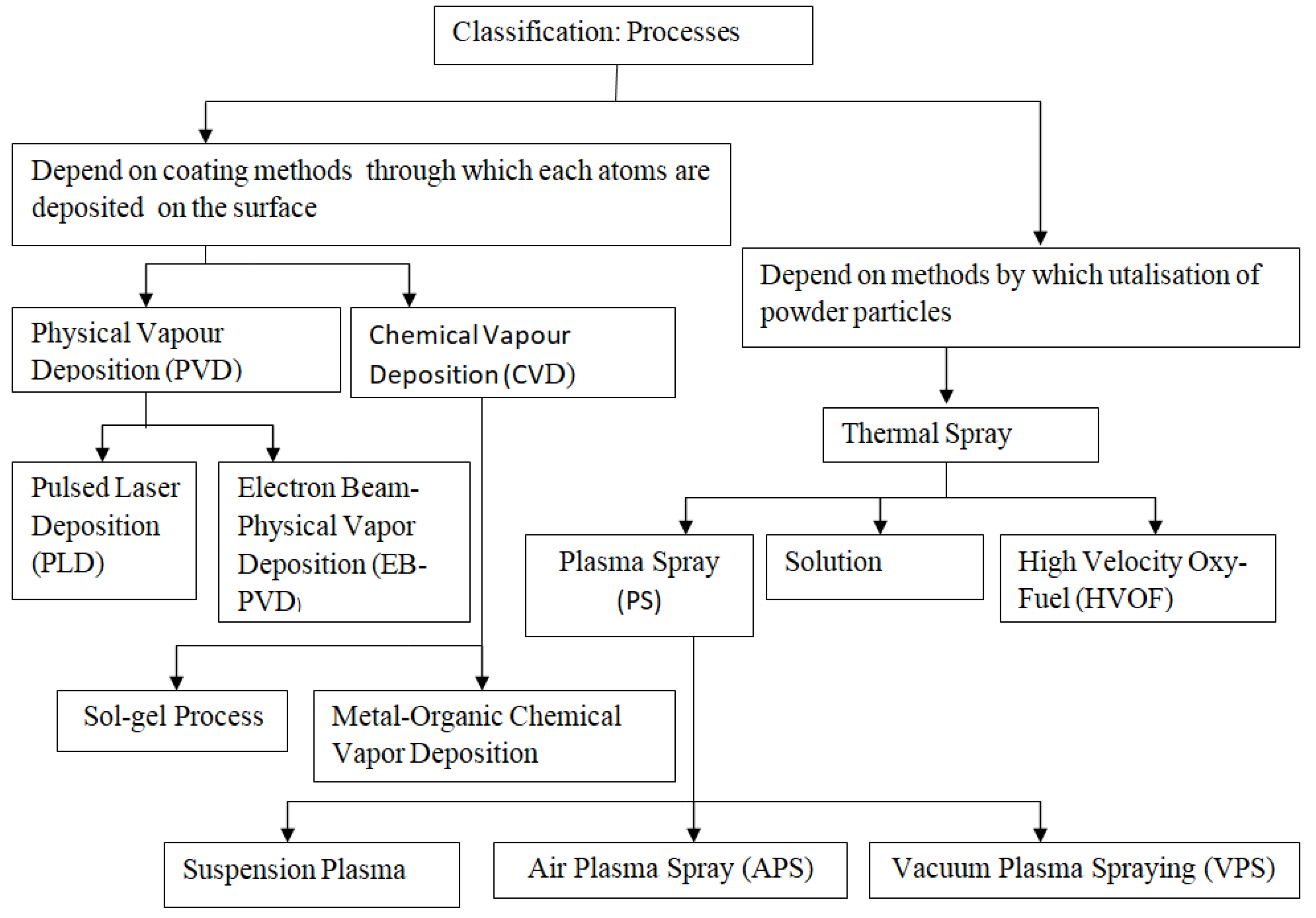
2.2. TBC Processing Methods

As shown in Figure 5, it offers a specific classification of processing techniques and the necessary process employed to deposition TBCs on the substrate metal, which has been mentioned in the following paragraphs. In the field of thermal spray, thermal plasmas are employed in atmospheric plasma spray (APS), suspension plasma spraying (SPS), solution precursor plasma spray (SPPS), Plasma Spraying –Physical Vapour Deposition (PS-PVD) vacuum plasma spray (VPS), low-pressure plasma spray (LPPS), and controlled atmospheric plasma spray (CAPS) methods.
The following sections extensively discuss atmospheric plasma spray (APS) because it is a standard coating method that can model typical thermal spray processes. Because of the relative amount of momentum supplied to the in-flight particles, plasma jet flow alters the trajectories of feedstock [29,30,31].

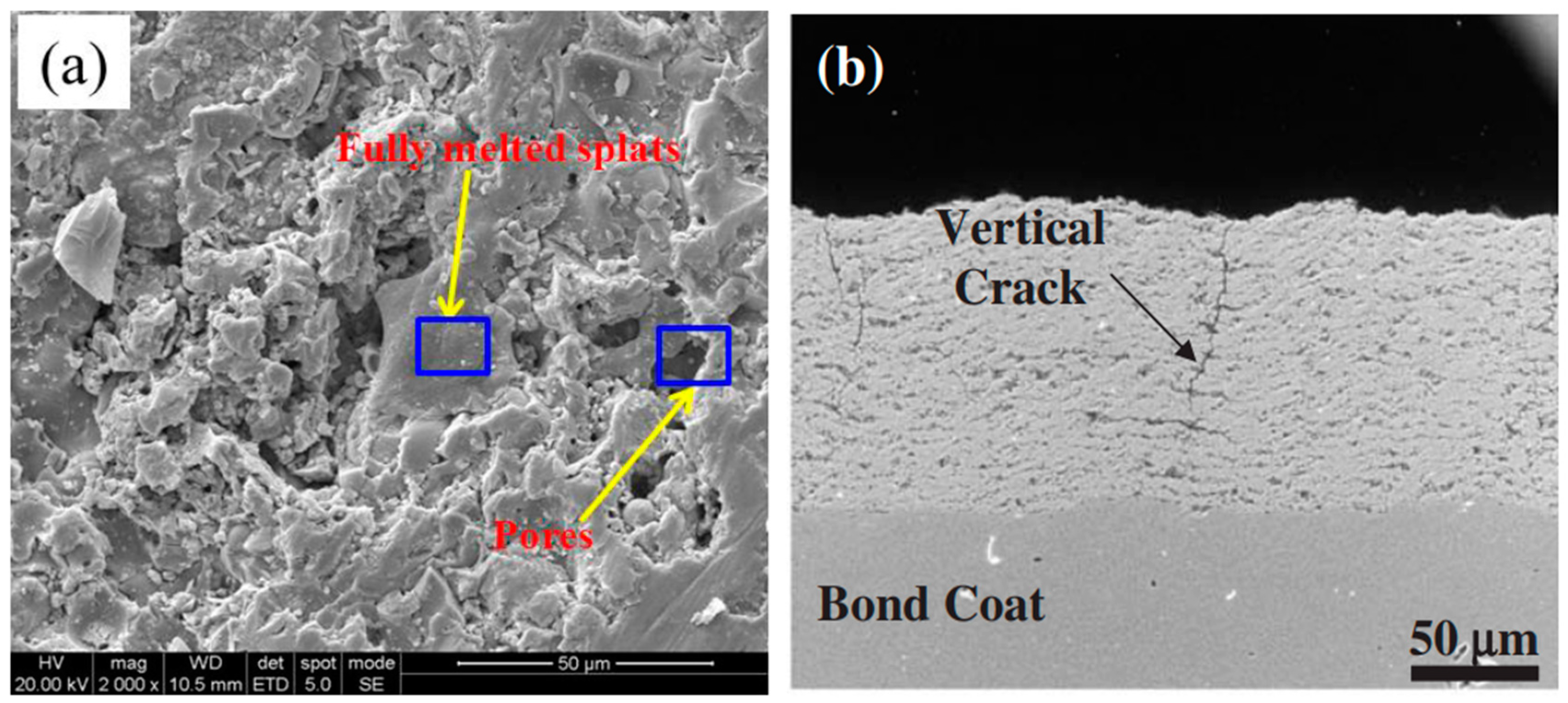
2.2.1. Air Plasma Spray (APS)

This TBC material-deposited method typically defines this type of part coating to the spray jet, such as atmospheric plasma spraying (APS). In common, APS coated appear to have a horizontal splatted micro-structure with inter-splatted borders approximately equal for this top-coated and bond-coated interfacial [32]. In this method, powdered material grains are injected in a thermal spray jet of higher heating range and melted within this jet of spray, which works for stimulation into the base metal where melted droplets spread that create splits efficiently quenched. The coated surface thickness can be increased by raising the number of successful splats deposited on the substrate metal. This coated structure quality mainly depends on the process parameters used for thermal sprays, such as the current, voltage, the flow rate of that gas, and the stand-off distance between the touch gun and substrate material during surface coating. The feedstock plays a vital role in supplying a sufficient amount of powder through the spray gun to obtain a successful coating structure. The feeder input parameters used to control this supply of powder grains include the temperature and size of the powder grains. The coated microstructure splats’ morphology depends on the angle of contact used to spray the powder grains to the substrate material [33]. Some usually cracked cross-sections for this powder spraying coated surface by APS show films for the splatted simultaneously with inter-laminar holes and round holes [34]. The coating’s porosity is structured depending upon the substrate’s surface temperature being reduced by increasing heat temperature and improving internal splat attachment, resulting in improved coating characteristics [35].
Figure 6 shows the powder’s morphology used for deposition in the substrate metal by the APS method in the existing work explained. The mean size was 40–70 μm for all globular agglomerated powder grains.
Figure 7 displays the FE-SEM images of the APS method-based individual-layered YSZ cross-sectional view, YSZ overlay of Al2O3, and YSZ coating overlay of CeO2. Besides, Al2O3 and CeO2 coatings are also considered crack-free and well adhered to the coating of the YSZ.
As shown in Figure 8, all three layers contained a bimodal microstructure consisting of an entirely melted section joined collectively to create a solid structure. The sponge-shaped microstructure portion is formed near the molten zone. APS coatings’ common characteristics, intermittently partially melted powder grains, micro-level cracks, and porosity play a significant role in the coated structure’s thermal oxidation and corrosion resistance behavior. As diffusion paths for molten salts, these partially melted power grains and micro-cracks work by enhancing the corrosion reaction between the dissolved salts and the ceramic powder [36].
Thermally grown oxide (TGO) mainly occurs between the top and bond coating structures because oxidation occurs during work at higher temperatures. The oxide layer growth mainly produced the maximum amount of stress inside the coating structure interface, which reduced the components’ service life. Experimental findings revealed that YSZ coating with Al2O3 as an overlay improved traditional YSZ’s hot corrosion protection by partly alleviating melted salt infiltration. However, by completely clearing the molten salt’s penetration in the YSZ, the YSZ layer with CeO2as the overlay film showed more effective corrosion protection than traditional TBCs [36]. Young’s modulus is the most significant factor in TBCs that influences the thermal stress distribution in the coating structure’s upper surface and improves the components’ work performance. Because of the porous microstructure, the upper surface’s macro-elastic properties are usually significantly less than this value for dense YSZ [37] (see Table 1). The relationship between the various parameters is shown in Figure 9. The failure of the bonded structure in cracks appears near the splats region because of expanding numbers of thermal cycles during the experiment work and increasing the strain value, which affects the reduced macro-elastic strength [38]. To determine the modulus of elasticity for the coated structure with depth-sensitive indentation, the methods were used, and stability depended upon the load applied for nanoindentation. With the heat treatment method’s help, the modulus of elasticity can be improved by heating the coated surface at 1100 °C [39].
As shown in Figure 10, the H2 or Ar can be used as carrier gases in APS coating. These gases entered from the electrode hole that heated up and disintegrated them through the arc to form plasma. The nozzle can control the jet of plasma in this process by regulating the speed and flow rate of the burning gases. These burning gases are mainly used as carrier gases in this method. They mix into agglomerated nano- or micro-sized diameter powder grains that help melt them before being deposited on the substrate material. Many process parameters have been used in the APS method. However, some of the most significant parameters must be affected by the surface’s standardized coated properties and improve the microstructure quality.
Some necessary input parameters that must be controlled for better microstructure from the coated surface, such as the pressure of gas arc feed rate of powder grains, diameters of powder particles, the flow rate of carrier gas, angle of injection, the distance of spray, smoothness of the coated surface and base metal or metal substrate surface temperature before coating start [41] (see Table 1). Several research types have confirmed that the optimum parameters in this process play a significant role in APS. It controls phase structure and thermal durability, improves microstructure, enhances corrosion protection, and improves physical properties, such as the coating’s hardness and toughness.

2.2.2. Functionally Graded Coatings

Traditional coated methods have faced significant problems under working conditions. This coated structure usually fails earlier when presented under the thermal shock and erosion test due to this causing the spallation effect produced in a material that can start deteriorated coated structured from the interface between top and bond coat. In functionally graded (FG)coatings, multiple phases are produced and given a regular face structure. The ceramic topcoat faces a higher operating temperature under this coating system and sustains this heat under the combustion chamber, while this also functions as heat insulation [42]. The coating must be done by depositing gradient material at a controlled amount to substrate metal during the process. The gradient material allows for the proper distribution of the stress generated around the coated surface and causes a decrease in strength. The bond coat strength has improved by reducing the thermal expansion gap between the top coated film and base metal after coating. When the higher amount of coated material is deposited through the spray drawing process and the diameter of traditional powder in microns used for coating, then the maximum chances for the spallation at the coating layer’s outer surface are then given. Some authors have produced nanostructured powder grains that troubleshoot this material spallation difficulty using nanostructured powder structured in YSZ TBCs material with a higher thermal expansion coefficient and lesser thermal conductivity overall [43]. Different studies have focused on the effectiveness of various kinds of functionally graded coatings in decreasing heat stress and improving the coated structure’s mechanical properties, such as thermal shock resistance and excellent hardness value [44]. Some researchers deposit the Al2O3/YSZ ceramic powder onto substrate materials and analyze its mechanical and thermal properties. The oxygen entrance is restricted by applying a thin surface coating of Al2O3 ceramic material and providing substrate metal thermal insulation. Spallation has formed inside the Al2O3 ceramic thick-coated structure while working at a higher temperature than can change the ceramic material phase from γ-Al2O3 to α-Al2O3. The coating material’s premature failure occurs when extra residual stress is generated inside the coating structure due to thermal oxidation [45]. This study will design a zirconium base coating material and examine fracture toughness using a theoretical modeling technique. This coating was done through the functionally graded process. A unique parameter is similar to the stress-intensity factor introduced to determine the toughening effect transform toughness equal to stress. The design methodology helps select optimal coating parameters that prevent the coated structure’s premature failure and improve the fracture toughness material [46].
Figure 11 represents every layer’s purpose inside the functional zones of this functionally graded coating (FGC) technique. In hot corrosion conditions, the stimulation decomposed for the Sm2Zr2O7 + 8YSZ way into the form of APS for the double ceramic layer (DCL) and functionally graded system (FGS) modes was examined. This investigation was to distinguish surface methods in a liquid sodium sulfate Na2SO4 environment that occur throughout the corrosion of FGC based on samarium zirconate and zirconium oxide with ratios 25/75, 50/50, and 75/25. After experimentation, the selective breakdown of samarium zirconate in the 50 8YSZ + 50 Sm2Zr2O7 composition that system gave better corrosion resistance compared to others [47].
The functionally graded coating material with thermal diffusivity/conductivity progressively improved over the functionally graded zones compared to the variation in composition accompanying this coating mechanism; the testing specimens were compared. The thermal oxidation test was conducted at a temperature of 1300 °C for 1 h, and the cooling process was done at 25 °C for 20 min for holding time to completion of one cycle. The composite layers’ thermal conductivity and diffusivity improved by increasing the NiCoCrAlY content and temperature, varying from 500 to 1200 °C. This investigation outcome explained that the functionally graded coating material’s thermal oxidation stability was five times higher than that of the conventional coating process for equivalent thicknesses. As shown in Figure 12a,b, it represents the thermal diffusivity and conductivity done at a variable temperature (from 25 to 1200 °C) and densities (0, 50, 75 and 100%). Figure 12c illustrates that FGC has improved thermal conductivity five times higher than a conventional coating, and the surface’s quality is dependent on each coating layer’s porosity level [48].

2.2.3. Multi-Layered Coatings

Multi-layer topcoat fabrication is an effective method to overcome the common problem and transform it into YSZ-based TBCs. The essential requirement for this multi-layered coated structure is to improve the stability and durability that results are required to increase the work performance. The multi-layer coated microstructure contains different coated films deposited in this coated structure and products, decreasing its thermal radiation effect [49]. A multi-layered idea has been used for the too-reflective coated system, including several stacks that can lower material outside temperatures and increase thermal efficiency [50].

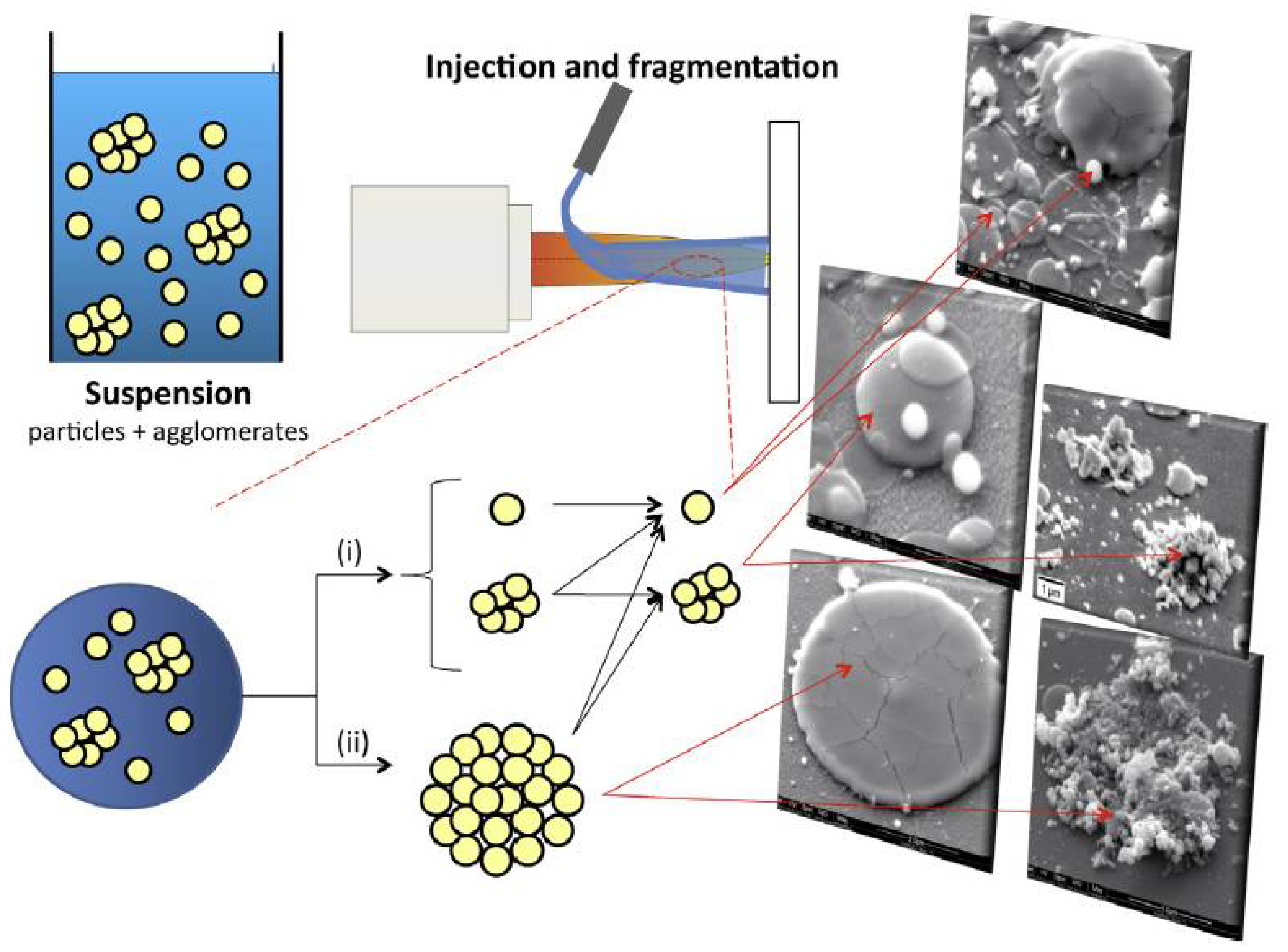
2.2.4. Suspension Plasma Spraying (SPS)

The suspension plasma spraying (SPS) system is mainly used for the required high-quality coated microstructure, which has primarily developed from the traditional plasma spraying process. This method can help establish a new composite coated micro-structured quickly onto the substrate material. The coating of structured material features can be improved using agglomerated nanostructured powder grains to reduce porosity [51]. The transport medium shifted from a gas state to a liquid form and observed the development of melted droplets that provided the required impulse [52]. Under this method, high-density state powder grains have been required to apply this surface coating technology, which has provided an uninterrupted supply for the molten droplets during working conditions. The diameter of the selected powder grains varies from 10 to 100 μm [53]. This has remained a complicated duty because this viscosity for the molten feedstock principally affects melted droplet generation inside the jet of spray, and the melting temperature depends on the diameter of the powder grain. This upper surface topography of the coated structure mainly depended on the powder and heating supply rate for melting the powder grains [54]. In this process, some critical liquid state solvents, such as distillation water or de-ionization water, methanol and ethanol, have been employed for this surface coating method and enhance the quality of this coated microstructure.
The time used for evaporation from the liquid state in the jet of spray and surface tension plays a critical role in selecting the solvent [55]. That has found that more time was spent in the distilled water solvent based on suspension droplet-evaporation in the spray plasma jet; in the other case where ethanol was used as a solvent, that droplet took less time as a consequence of faster fragmentation. With two kinds of technology employed in SPS methods, the pressurised vessel and peristaltic pumps carried the sufficient liquid phase solvent and used supply to the spray jet at the required amount. The lower adhesion rate, higher fracture toughness, and higher thermal shock resistance all have structured coating properties that provide better durability or reliability under the required mechanical properties. The ASTM G171-03 standards were used to calculate the surface-coated structure’s cohesion rate and provided the other required information related to the coating [55]. The researcher conducted the harness value for the 8YSZ-coated design, which varied from 5 to 14 GPa, by conducting the SPS process experiments under the TBCs. In this process, the powder’s selection in coating is based on some important parameters, such as the shape of the crystal structure and the grain particle size, and provides better resistance to the coating surface from degradation [56]. The maximum thermal spray-based organization used 7 wt.% YSZ as a ceramic top-coated structure in TBCs because of the few novel properties given due to higher thermal resistance and enhanced fracture toughness [57]. For the highest efficiency and extended work life for these steam turbine blades, the high-temperature range for that YSZ thermal barrier coating is 1250 °C [58].
Figure 13 shows the system used for the injection and fragmentation of the molten powder grains during deposition on the substrate material. The single and agglomerated powder grains that remain in the suspension are delivered immediately and melted through the plasma jet. Single powder grains provide very tiny lamellae or sub-micrometric globular characteristics that have not flattened [59].
According to Van Every K et al. [60], the individual powder grains have to produce a lower amount of inertia to efficiently divert these powder particles. The stagnation of flow on the upper side of the base metal’s upper side can decrease the molten material’s required velocity, creating a low amount of flattened lamella.

2.2.5. Solution Precursor Plasma Spray (SPPS)

This surface coating technique has been recognized as an appropriate alternative for developing TBC at the lowest cost and has been upgraded for increased thermal cycles and decreased thermal conductivity [61]. The SPPS method, as shown in Figure 14, is very similar to the SPS technique, in which the coating material is supplied into the plasma spray by suspending dense particles into the nanostructured size range. Both procedures use comparable liquid injection methods and have the same problem of evaporating the suspending medium or solvent, which requires a significant amount of energy. The atomized precursor is used as a feedstock to transmit the chemical precursor by injecting this aqueous form solution into the plasma jet. It is also helpful for fast physical reactions inside the plasma region [62]. This method consists of organic or inorganic solvents, compounds of metallic-organic and inorganic salts used to complete the process [63].
The liquid precursor injection technique is similar to the suspension plasma spray technique, but the coating development system is somewhat different. Cracks in SPPS coatings emerge as the deposited semi-pyrolyzed materials contract owing to subsequent in-process heating, as demonstrated in Figure 15b, stress-relieving throughout the thickness. They are not restricted to dense coatings. The fact that the splat sizes are on the 1–5 µm order, more than 10 times less than the average powder-sprayed splats, is another unique aspect of the SPPS process (Figure 15a) [64,65]. There are some essential features of the SPPS-coated method that can be developed as an evenly ordered porosity effect and the regular separation of vertical cracked. The orientation of this base metal helps increase thermal stability and enhances the coated surface’s bond strength [66].
The non-melted powder grains and extremely fine-sized splatted deposited on the substrate material must be observed in this coating method. Any non-melted powder grains holding a non-pyrolyzed precursor appear to deteriorate and crystallise throughout the thermal shock test. A lesser stand-off distance must be required in the SPPS method than in the traditional coating method and provided superior quality of a surface structure [67]. The organic or inorganic solution was used to dissolve the micro- or nanostructured powder grains and prepare the suspension. The appropriate dispersion has been used to adsorb the outer region to the powder gains combined into this suspension system to control their stability and prevent these agglomerated powder grains. The suspension system gave less viscosity to dissolve the powder grain at the appropriate level. The suspension’s rheological properties have been significantly influenced by particle size, powder surface composition, solid loadings, and dispersant rate [68]. Powder grains are synthesized to be helpful for synchronous deposition onto the coating process’s substrate material [69]. The change in grain powder symmetry can significantly impact the relative adjustable chemical structure [70]. The jet of plasma has been classified into three zones, depending on temperature variation: the plasma jet core, plasma plume, and plasma fringe. In this method, the injection mode, such as suspension and solution, has played a significant role that can be affected by the droplets’ heated temperature [71]. The injector is used to precisely control the molten droplet’s speed before depositing it onto the base metal. Other instruments, such as peristaltic and plunger pumps, can transport liquid material in this system. Having the fluid penetrate inside the plasma jet core is desirable and comparatively simple to accomplish under this axial injection method. The radial injection method has commonly been accepted commercially because of its low deposition cost and better-quality deposition [72]. The extra power required for automatizing the fluid at a slower speed can overcome this problem by employing Ar gas because it has a greater specific mass. The spray gun nozzle can carry two different liquids and produce the atomization effect at the coating [73].

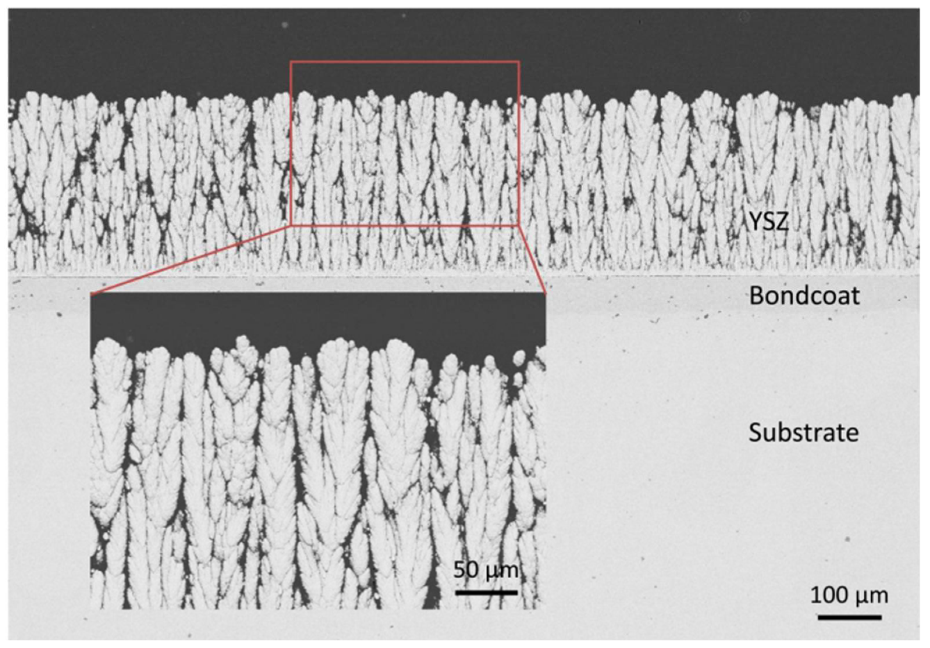
2.2.6. Plasma Spraying-Physical Vapor Deposition (PS-PVD)

The injected powder material is melted into liquid droplets and evaporates to form a coating using this method. This coating method is used in plasma spray and is designed to minimize the oxidation effect throughout deposition phases to the base material’s ceramic materials. The plasma spraying physical vapor deposition (PS-PVD) process is further subdivided into two categories: low-pressure plasma spraying (LPPS) and vacuum plasma spraying (VPS). Improvements under advanced vacuum plasma spraying methods, such as plasma spraying physical vapor deposited (PS-PVD), plasma spraying chemical vapor deposited (PS-CVD), and thin-film LPPS, have recently occurred. The gas-phase use for coating and the chamber operating pressure (>100 Pa) have some significant characteristics for this method [74]. Compared to conventional Air Plasma Spray, the PS-PVD is used as an advanced coating method. It can provide the ceramic material’s with fast deposit onto the substrate metal. To improve the LPPS coating method’s working efficiency by increasing the vacuum pressure from 50 to 200 Pa inside the processing room, the 200 NLPM (Normal Liters Per Minute) required a flow rate and 180 kW power to operate the plasma gun for a spray for plasma gas for the coating process. Thin film technology, which allows for the creation of uniform, homogenous coatings, may produce the thinnest coatings [75]. The protection of the base material from overheat was a major challenge during the coating process and overcame this controlled movement of the plasma gun. Some researchers have developed the bond coat material structure and controlled the plasma gun’s power requirement, which depends on the coating material composition and powder particles [75]. The evaporation of the powder grains starts in the PS-PVD process due to the higher temperatures achieved for the plasma plume during the working process. The smoother powder grains provided more benefits for evaporation starting in the plasma plume in the deposition process. The coated surface’s microstructure depends on the parameters and the powder grains’ diameter during the coating process [76]. The compound of Ar/He2 gases is used to generate the plasma in the PS-PVD process and the YSZ powder grains’ feed rate is 80 g/min for obtaining optimum work performance. It is pumped into the plasma gun to guarantee that the powder particles penetrate the plasma core. The nanostructure cluster is made from a columnar structure shape due to the lesser feed rate of powder grains and generation Ar/He2 gases for plasma. The EB-PVD coating method isalso suitable for obtaining a columnar structure shape at a 2 g/min required feed rate of the coating material [76]. The spray parameters can control the type of layer structure, transforming it from a splat-type coating to a porous layer type and eventually to a columnar microstructure.
As shown in Figure 16, the columnar structure requirement is achieved by combining a low powder feed rate, a specific mixture of argon, secondary plasma gases and a considerable spray distance [77].

3. Failure Mechanism in Thermal Barrier Coatings

The mechanism responsible for the failure of thermal barrier coatings is discussed in this section. The TBCs have to withstand high temperature oxidation, hot carrion and erosion. The rapid oxidation of materials at high temperatures caused by a thin layer of dissolved salt deposits is hot corrosion. The TBCs should have the properties to resist such failures and these have been presented in Figure 17.

3.1. Some Challenges and Required Properties in the Selection of Coating Material

TBCs are coated processes used for intricate surface material systems that are useful for gas turbine engines implemented in hot regions.
TBC coatings are exposed to the harsh environment of the combustion chamber. The following challenges face TBCs: hot corrosion, thermal oxidation performance and hardness values.

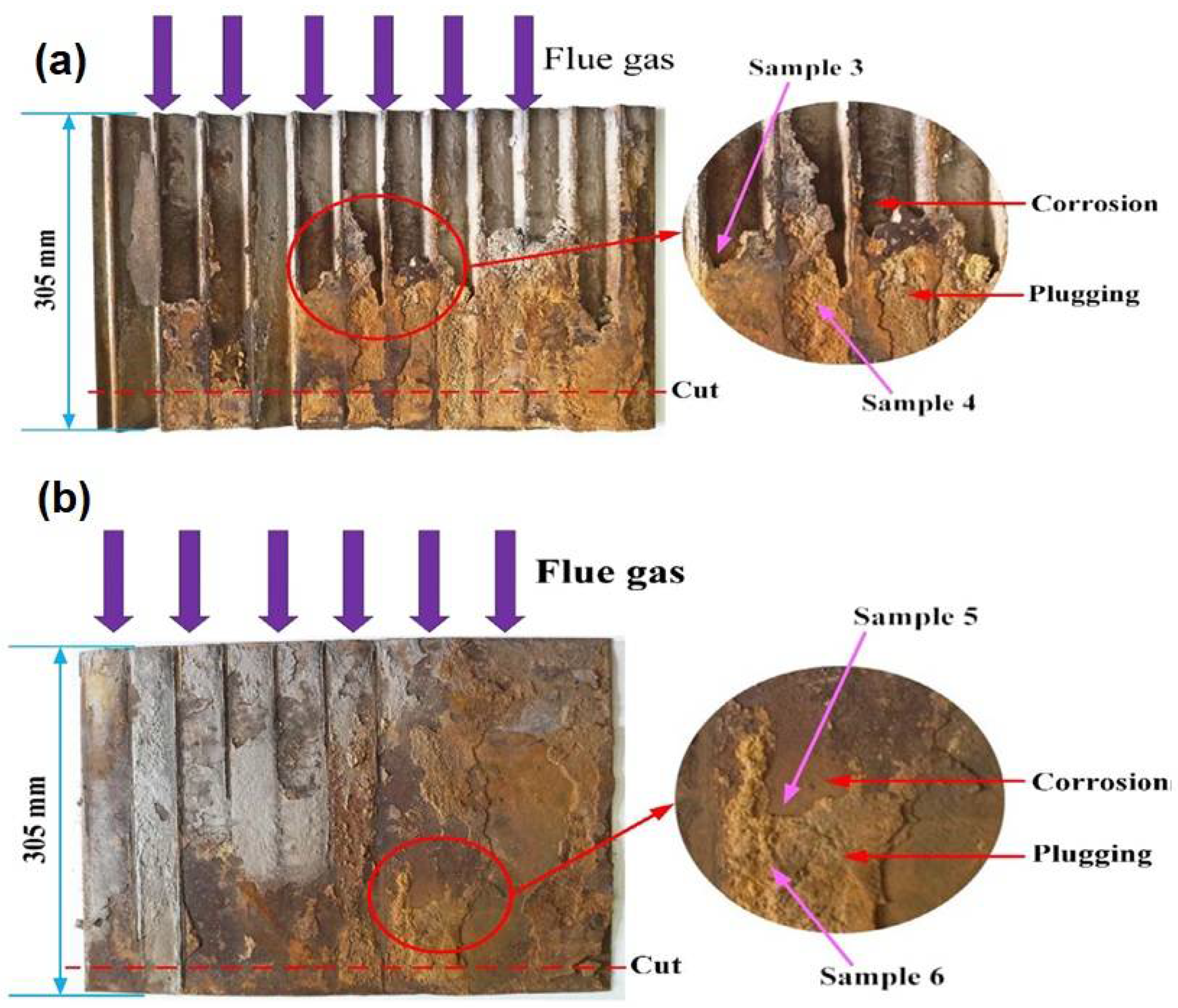
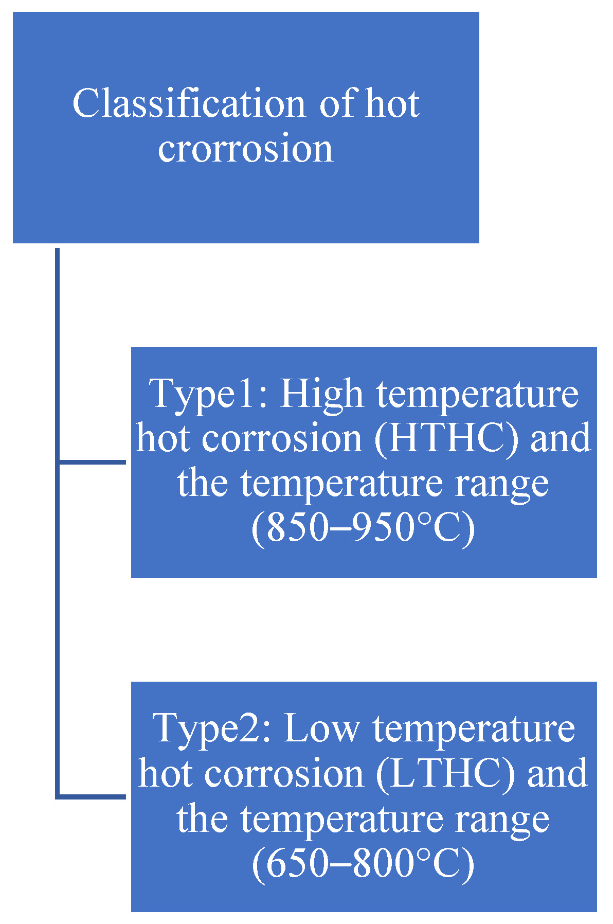
3.1.1. Hot Corrosion

The rapid oxidation of materials at high temperatures caused by a thin layer of dissolved salt deposits is hot corrosion [78]. Sulfur is present in lower-grade fuels, where it produces SO2 on combustion and is slightly oxidized to SO3. Sodium chloride (NaCl) combines with water vapor and SO3 at combustion temperature to form sodium sulphate (Na2SO4), which has a melting point of 884 °C [79].
Low-carbon steel and corten steel are mainly used to manufacture boiler parts in fired coal-based thermal power plants. Superheater tubes, water walls, and economizers are essential parts of the pant. They are exposed to extremely high temperatures, pressures and corrosive environments during the plant’s working. This corrosive environment of the original boiler atmosphere contains sulfur, carbon and oxygen, which can cause material degradation and early boiler tube rupture, especially in higher temperature ranges (Figure 18) [80].

Different Kinds of Hot Corrosion

There are two sorts of attacks when it comes to hot corrosion (Figure 19):
(a)
High-temperature hot corrosion (HTHC)
(b)
Low-temperature hot corrosion (LTHC)
The coating material and coating method must be selected according to the application of the metallic component [81].

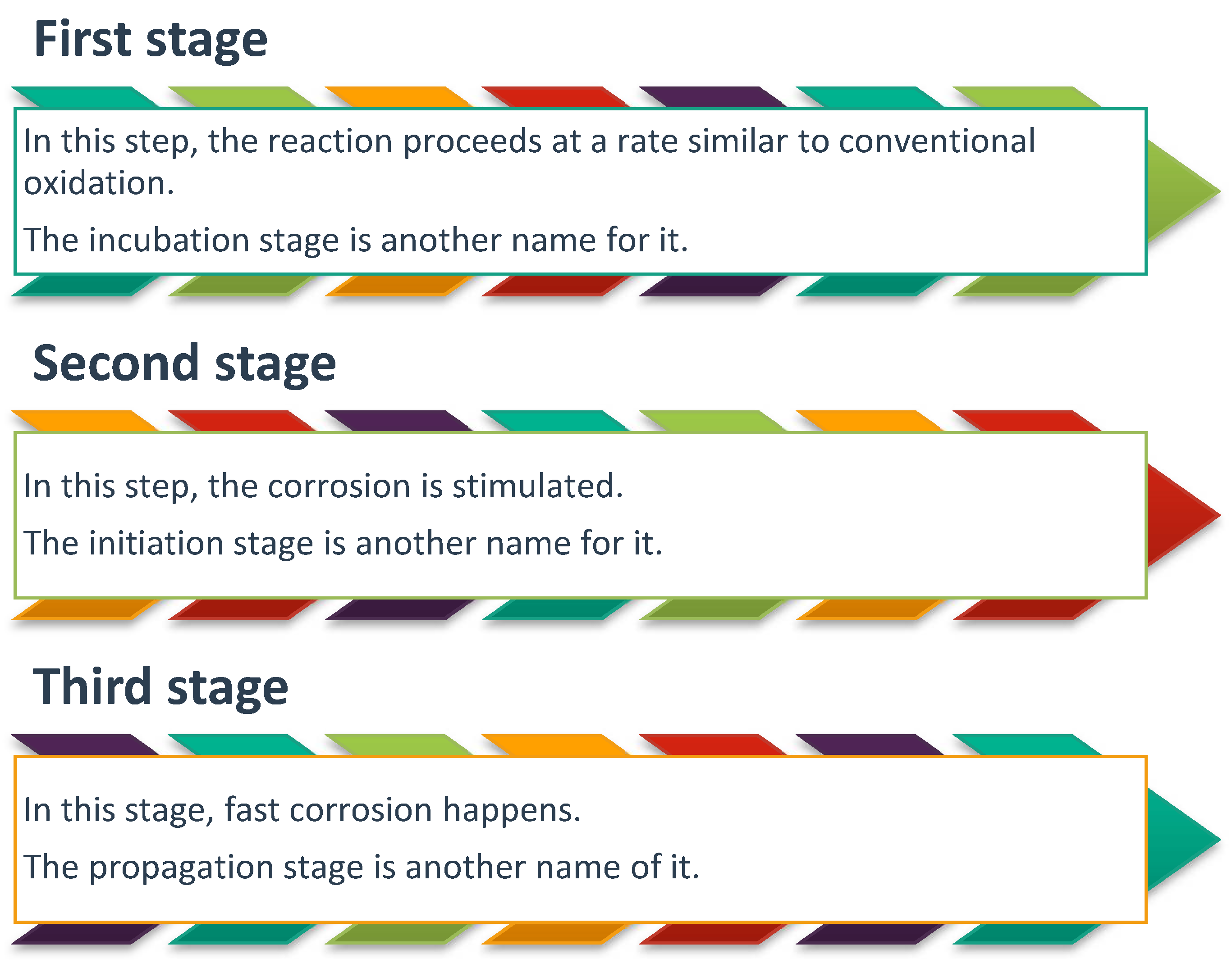
Mechanism of Hot Corrosion and Stages

Numerous authors have proposed several methods to characterize the hot corrosion method [81]. As shown in Figure 20, the hot corrosion of metal alloys occurs in three different stages. The corroded metal alloy part’s final failure occurs after the third stage is completed.

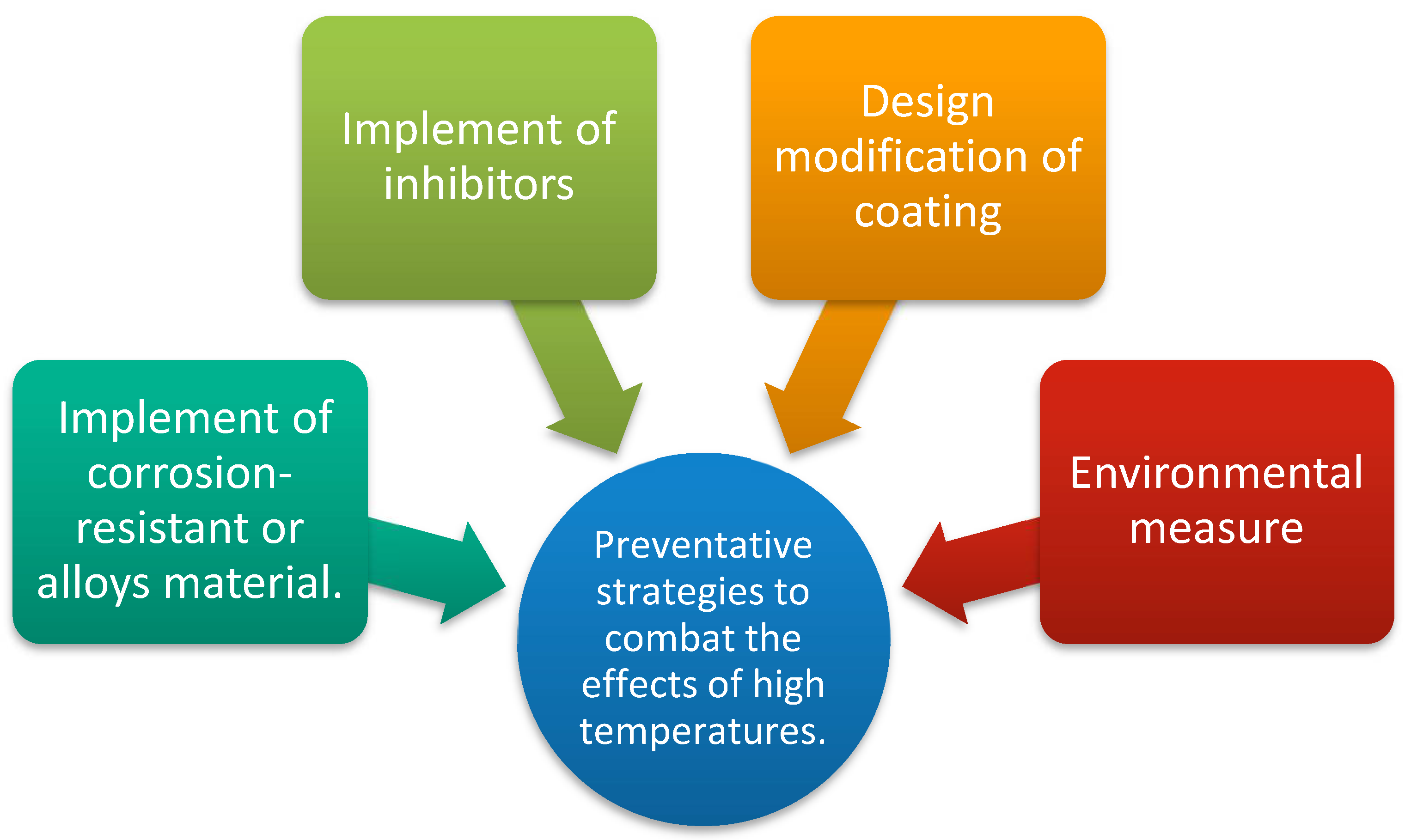
Preventive Strategies to Combat the Effect of High Temperature

As shown in Figure 21, some preventive techniques have been proposed for excessive material degradation caused by high-temperature corrosive environmental conditions [82].

Composite Coating Hot Corrosion Behavior

The composite coating was developed by the researchers for the design modification of coating structures. The 3YSZ-Ni composites have magnetic properties, and for this reason, they can be used as superior surface coating materials and have provided tremendous ability to be used in various working environmental sectors. Solid oxide fuel cell materials (SOFC) can help the ceramic’s stability and can be used in the thermal spray deposition process to improve quality surface texture. The thermal barrier coating technique mainly uses high-temperature industrial applications, such as the aerospace industry, to protect the gas turbine components, diesel engine exhaust manifold, and cutting tools application [83,84,85].
A comprises intra splat fractures, interlamellar pores, and globular pores of various sizes. The porosity of the coating film was calculated using an image analysis procedure from the SEM image (Figure 22). A polished cross-section with Al2O3/8YSZ TBC coating had an estimated porosity percentage value of around 17%. The CeO2/8YSZ coating porosity was about 10% lower than that of the Al2O3/8YSZ coating [86].
The 1350 °C as the minimum temperature needed for the ceramic powder grains to achieve the desired rate of compactness on the coated surface structured and sintered effect can also improve the coating microstructure’s quality. High densification has been achieved by adding 1.0 mol nickel oxide to a ceramic-based coating material that has provided improved thermal stability in high-temperature thermal shock environmental conditions [87]. A tremendous quantity of research has been conducted on traditional coatings available in previous decades. On the other hand, there are few research types on functionally graded coatings, composite coatings, and bimodal coatings [42,87,88]. Some significant features of this fundamental powder microstructure have provided better corrosion resistance properties [49]. Some studies have represented the number of pores per unit of mass exercise for high importance denser kinetics, influencing microstructural evolution properties during the thermal oxidation test [89]. The Ni/YSZ’s shows a great-energy interference by Ni-base powder grains ceramic material over 20 vol.%, which did not exceed the percolation threshold. The electrical conductivity and complicated impedance used for measures corresponded to a nickel concentration of 34 vol.% in TZP ceramic powder grains [90]. A huge percolation threshold has been associated with one unfinished initial-near order, such as ferrous metal composition within ceramic powder grain materials [91]. The addition of nickel to 3YSZ is transmitted for supreme power to ball milling, and those composites manifest to develop in the densification process. The purified form of nickel elements has represented an anti-prohibitionist tendency into zirconia material because unstable phases and the contact angle may vary from 117° to 122° [92]. Some researchers have proposed a straight reduction of the interfacial reaction among polycrystalline ZrO2 and the liquid phase of Ni, including heating energy, depending on which the interfacial potential at the melting heat for Ni is 1.668 J/m2 [93]. Selection of the nanometric size YSZ powder grains and micro-size of nickel-base powder grain added and then effectively mixing them through a ball milling machine and the highest shrinkage percentage heat for 3YSZ-Ni composites during the process. In this coating process, the two sides’ heating improved as the Ni content enhanced the melting temperature, affecting a decreased density with an enhanced Ni amount and a melting temperature rise [94].
Consequently, CeO2/YSZ coating exhibited excellent results by entirely preventing molten salts from flowing in YSZ. Researchers have worked to improve the hot corrosion resistance of YSZ coatings/materials, as shown in Table 2. The molten salts either entirely entered or partially permeated the YSZ covering (Table 2).

3.1.2. Thermal Oxidation Performance

The solid form grain particles are striking on the coated materials at very high velocity and high temperature, and then the surface starts to deteriorate. This phenomenon is known as thermal oxidation [105]. The average output of various substrate metals under thermal oxidation environmental conditions was examined in an organized manner, as presented in Table 3. Some significant coating powders have provided better resistance to thermal oxidation, such asAl2O3, CrO3, TiO2, YSZ, and NI-Cr-based coating. Numerous researchers have proposed decreasing the area of WC particles to the nanostructured to obtain greater power, high-toughness, and wear resistance for WC-Co-Cr coating [106]. Furthermore, the decarburization process’s effect occurs in nanostructure coatings. This process has a more comprehensive primary outside dimension by reducing the WC particles’ area [107].

3.1.3. Recent Approach Use for Improving Hardness and Toughness Values

Complex surface layers have usually been considered to have outstanding wear-resistance characteristics and help for high working temperatures. Several researchers working on the APS coating method find that by applying nanostructured YSZ coating powder to the substrate, metal can provide better coating results than micro-size powder, such as better surface finish and improved abrasion rate. The hardness values of the traditional layer are more meaningful than a nanostructured coating measured by a Vickers indenter test. The use of feedstock in a thermal spray to monitor agglomerated nanostructured powder particles’ critical parameters. The embedded most of the nanostructured grains melted after applying a plasma spray jet at a controlled feed rate, which can help form the smooth microstructure on the substrate material. The coated layer did not display any significant nanostructured quality. This layer tended to behave as a conventionalized one. Nanostructured thermal spray coatings show considerably more excellent resistance to crack propagation than conventional thermal spray coatings. The Vickers indentation technique analyses the creak propagation generated inside the surface coating layer, ensuring its quality and playing a vital role in selecting the proper coating methods. When applied to sufficient weights, the surface coating during Vickers indentation formed cracks and propagated a small distance that edges about the impact of a Vickers indentation. Therefore, the more significant wear of the nanostructured coatings is typically characteristic of excellent protection against crack spread (Table 4).
The Vickers-indentation morphology of nanostructure and traditional 8YSZ coatings where the load applied is 5 kgf (49 N) is shown in Figure 23. Figure 23 also shows that those produced cracks are thinner and shorter inside nanostructure 8YSZ coatings, while the generated cracks are coarser and longer in traditional 8YSZ layers [147]. Estimated and presented a few tests to show partially melted nanostructured powder grains deposited on that coated morphology. A spray jet tends to work mainly with crack arresters, thus improving coating toughness [148].
The Effect on Energy Efficiency of Yttria-Stabilized Zirconia non Brass, Copper and Hardened Steel Nozzle in Additive Manufacturing was analyzed, which is the recent advancement of the application of TBCs in additive manufacturing [149,150,151,152]. Other methods can also be used, such as electrochemical deposition regimes, to develop thin films [153,154]. Nano-composite materials can be used to counter hot corrosion in cases of high-temperature applications [33,155]. The YSZ coating system is going through a phase, where advancement in the composition is taking place [156] and the main process used for the deposition of ceramics is plasma spraying technique [157,158,159].

4. Perspectives and Summary

This research study’s primary focus is to analyze and summarize technical advancements concerning the essential features of TBCs, with stress on the correlation between the thermal, mechanical and erosion properties of the coating material by selecting the suitable coating method. In this research study, many efforts in this area aim to improve the microscopic-level properties of TBC materials that increase their durability while working in high-temperature and highly corrosive conditions to prepare them to fit for various industrial applications. This review article contains the introductory section and some other sections.
  • It discusses the context and applications of TBCs, the elements of a traditional TBC framework and their function and required properties.
  • A TBC system’s output is closely related to the methods used in its development. Different processing techniques and advancements in material depositing methods have versatile tailoring of their microstructure and combinations for special engineering applications.
  • Approaches used to TBC design and coating materials. Develop TBC; the different design methodologies are implemented to address the coating’s working specifications and stability. Those involve functionally graded coating, composite coating, and multi-layered coating arrangements, which are also discussed in this review.
  • Some challenges of TBC include improving performance during testing thermal oxidation, mechanical properties, such as hardness and toughness, and hot corrosion obtained from different coating materials and other material deposition techniques.
  • The recommendations for thermal barrier coatings include the use of electron beam-physical vapor deposition (EB-PVD) or plasma spray. Both of these processes can best rain compliant, have low thermal conductivity, and generate erosion-resistant coatings whose microstructures can be tailored for the desired application. Moreover, the composition of the top coat can vary with the addition of other phases.

Author Contributions

A.M., Original draft preparation; H.V., Supervisor, review and editing; S.S., supervisor; C.P., Conceptualization and visualization; K.K.S., Conceptualization; E.L., Formal analysis and funding; D.B., Formal analysis and software; J.X., Analysis. All authors have read and agreed to the published version of the manuscript.

Funding

This research was funded by a grant from the Romanian Ministry of Research, Innovation and Digitalization, project number PFE 26/30.12.2021, PERFORM-CDI@UPT100—The increasing of the performance of the Polytechnic University of Timișoara by strengthening the research, development and technological transfer capacity in the field of “Energy, Environment and Climate Change” at the beginning of the second century of its existence, within Program 1—Development of the national system of Research and Development, Subprogram 1.2—Institutional Performance—Institutional Development Projects—Excellence Funding Projects in RDI, PNCDI III.

Institutional Review Board Statement

Not applicable.

Informed Consent Statement

Not applicable.

Data Availability Statement

The authors did not report any data other than manuscript.

Conflicts of Interest

The authors declare no conflict of interest.

References

  1. Anheden, M. Analysis of Gas Turbine Systems for Sustainable Energy Conversion. Ph.D. Thesis, KTH, Stockholm, Sweden, 2000. [Google Scholar]
  2. Gupta, K.; Rehman, A.; Sarviya, R. Bio-fuels for the gas turbine: A review. Renew. Sustain. Energy Rev. 2010, 14, 2946–2955. [Google Scholar] [CrossRef]
  3. Myoung, S.-W.; Lee, S.-S.; Kim, H.-S.; Kim, M.-S.; Jung, Y.-G.; Jung, S.-I.; Woo, T.-K.; Paik, U. Effect of post heat treatment on thermal durability of thermal barrier coatings in thermal fatigue tests. Surf. Coat. Technol. 2013, 215, 46–51. [Google Scholar] [CrossRef]
  4. Ahmaniemi, S.; Vuoristo, P.; Mäntylä, T.; Gualco, C.; Bonadei, A.; Di Maggio, R. Thermal cycling resistance of modified thick thermal barrier coatings. Surf. Coat. Technol. 2005, 190, 378–387. [Google Scholar] [CrossRef]
  5. Bhatia, T.; Ozturk, A.; Xie, L.; Jordan, E.H.; Cetegen, B.M.; Gell, M.; Ma, X.; Padture, N. Mechanisms of ceramic coating deposition in solution-precursor plasma spray. J. Mater. Res. 2002, 17, 2363–2372. [Google Scholar] [CrossRef]
  6. Hille, T.S.; Nijdam, T.J.; Suiker, A.S.; Turteltaub, S.; Sloof, W.G. Damage growth triggered by interface irregularities in thermal barrier coatings. Acta Mater. 2009, 57, 2624–2630. [Google Scholar] [CrossRef]
  7. Reed, R.C. The Superalloys: Fundamentals and Applications; Cambridge University Press: Cambridge, UK, 2008. [Google Scholar]
  8. Boyce, M. Gas Turbine Engineering Handbook, 4th ed.; Elsevier Inc.: Cambridge, MA, USA, 2012. [Google Scholar]
  9. Bose, S. High Temperature Coatings; Butterworth-Heinemann: Oxford, UK, 2017. [Google Scholar]
  10. Kaysser, W. Surface Modifications in Aerospace Applications. Surf. Eng. 2001, 17, 305–312. [Google Scholar] [CrossRef]
  11. Ahmad, A.; Khan, S.; Tariq, S.; Luque, R.; Verpoort, F. Self-sacrifice MOFs for heterogeneous catalysis: Synthesis mechanisms and future perspectives. Mater. Today 2022, 55, 137–169. [Google Scholar] [CrossRef]
  12. Shankar, A.R.; Bellam, J.B.; Sole, R.; Mudali, U.K.; Khatak, H.S. Laser remelting of plasma sprayed zirconia based ceramic coating for pyrochemical reprocessing applications. Surf. Eng. 2007, 23, 147–154. [Google Scholar] [CrossRef]
  13. Jamali, H.; Mozafarinia, R.; Razavi, R.S.; Ahmadi-Pidani, R. Comparison of thermal shock resistances of plasma-sprayed nanostructured and conventional yttria stabilized zirconia thermal barrier coatings. Ceram. Int. 2012, 38, 6705–6712. [Google Scholar] [CrossRef]
  14. Weng, W.-X.; Zheng, Z.-H.; Li, Q. Cracking evolution of atmospheric plasma-sprayed YSZ thermal barrier coatings subjected to isothermal heat treatment. Surf. Coat. Technol. 2020, 402, 125924. [Google Scholar] [CrossRef]
  15. Bai, Y.; Wang, Y.H.; Wang, Z.; Fu, Q.Q.; Han, Z.H. Influence of unmelted nanoparticles on properties of YSZ nano-coatings. Surf. Eng. 2014, 30, 568–572. [Google Scholar] [CrossRef]
  16. Pourbafrani, M.; Razavi, R.S.; Bakhshi, S.R.; Loghman-Estarki, M.R.; Jamali, H. Effect of microstructure and phase of nanostructured YSZ thermal barrier coatings on its thermal shock behaviour. Surf. Eng. 2014, 31, 64–73. [Google Scholar] [CrossRef]
  17. Lima, R.; Marple, B.R. Nanostructured YSZ thermal barrier coatings engineered to counteract sintering effects. Mater. Sci. Eng. A 2008, 485, 182–193. [Google Scholar] [CrossRef]
  18. Deng, W.; Zhao, X.; An, Y.; Chen, J.; Zhou, H. Study on preparation and tribological properties of as-sprayed 8YSZ/Graphite coating. Surf. Eng. 2019, 36, 1097–1106. [Google Scholar] [CrossRef]
  19. Zhao, Y.; Gao, Y. Deposition of nanostructured YSZ coating from spray-dried particles with no heat treatment. Appl. Surf. Sci. 2015, 346, 406–414. [Google Scholar] [CrossRef]
  20. Aruna, S.T.; Srinivas, G. Wear and corrosion resistant properties of electrodeposited Ni composite coating containing Al2O3–TiO2 composite powder. Surf. Eng. 2015, 31, 708–713. [Google Scholar] [CrossRef]
  21. Wang, J.; Sun, J.; Zhang, H.; Dong, S.; Jiang, J.; Deng, L.; Zhou, X.; Cao, X. Effect of spraying power on microstructure and property of nanostructured YSZ thermal barrier coatings. J. Alloys Compd. 2018, 730, 471–482. [Google Scholar] [CrossRef]
  22. Da, B.; Yongxin, G.; Yaxuan, L.; Yongguang, W.; Yongwu, Z. Mechanical behaviour of graded chemically bonded ceramic coating. Surf. Eng. 2020, 37, 618–623. [Google Scholar] [CrossRef]
  23. Gao, M.; Xu, N.; Zhang, J.; Luan, S.; Chang, H.; Hou, W.; Chang, X. Influence of mechanical properties on thermal shock resistance of TBCs. Surf. Eng. 2020, 37, 572–580. [Google Scholar] [CrossRef]
  24. Wang, H.-X.; Zhang, Y.; Cheng, J.-L.; Li, Y.-S. High temperature oxidation resistance and microstructure change of aluminized coating on copper substrate. Trans. Nonferrous Met. Soc. China 2015, 25, 184–190. [Google Scholar] [CrossRef]
  25. Che, C.; Wu, G.Q.; Qi, H.Y.; Huang, Z.; Yang, X.G. Effect of bond coat surface roughness on oxidation behaviour of air plasma sprayed thermal barrier coatings. Surf. Eng. 2008, 24, 276–279. [Google Scholar] [CrossRef]
  26. Staia, M.H.; Mejias, A.; La Barbera, J.; Puchi-Cabrera, E.; Villalobos-Gutierrez, C.; Santana, Y.Y.; Montagne, A.; Iost, A.; Rodriguez, M.A. Mechanical properties of WC/Co-CNT HVOF sprayed coatings. Surf. Eng. 2018, 36, 1156–1164. [Google Scholar] [CrossRef]
  27. Ghosh, D.; Das, S.; Roy, H.; Mitra, S.K. Oxidation behaviour of nanostructured YSZ plasma sprayed coated Inconel alloy. Surf. Eng. 2016, 34, 22–29. [Google Scholar] [CrossRef]
  28. Yin, B.; Zhou, H.D.; Yi, D.L.; Chen, J.M.; Yan, F.Y. Microsliding wear behaviour of HVOF sprayed conventional and nanostructured WC–12Co coatings at elevated temperatures. Surf. Eng. 2010, 26, 469–477. [Google Scholar] [CrossRef]
  29. Cetegen, B.M.; Yu, W. In-situ particle temperature, velocity, and size measurements in DC arc plasma thermal sprays. J. Therm. Spray Technol. 1999, 8, 57–67. [Google Scholar] [CrossRef]
  30. Han, M.-C.; Cai, S.-Z.; Wang, J.; He, H.-W. Single-Side Superhydrophobicity in Si3N4-Doped and SiO2-Treated Polypropylene Nonwoven Webs with Antibacterial Activity. Polymers 2022, 14, 2952. [Google Scholar] [CrossRef]
  31. Das, D.; Sivakumar, R. Modelling of the temperature and the velocity of ceramic powder particles in a plasma flame—II. Zirconia. Acta Met. Mater. 1990, 38, 2193–2198. [Google Scholar] [CrossRef]
  32. Shin, D.; Hamed, A. Influence of micro–structure on erosion resistance of plasma sprayed 7YSZ thermal barrier coating under gas turbine operating conditions. Wear 2018, 396–397, 34–47. [Google Scholar] [CrossRef]
  33. Mehta, A.; Vasudev, H.; Singh, S. Recent developments in the designing of deposition of thermal barrier coatings—A review. Mater. Today Proc. 2020, 26, 1336–1342. [Google Scholar] [CrossRef]
  34. Kulkarni, A.; Vaidya, A.; Goland, A.; Sampath, S.; Herman, H. Processing effects on porosity-property correlations in plasma sprayed yttria-stabilized zirconia coatings. Mater. Sci. Eng. A 2003, 359, 100–111. [Google Scholar] [CrossRef]
  35. Huang, J.B.; Wang, W.Z.; Li, Y.J.; Fang, H.J.; Ye, D.D.; Zhang, X.C.; Tu, S.T. A novel strategy to control the microstructure of plasma-sprayed YSZ thermal barrier coatings. Surf. Coat. Technol. 2020, 402, 126304. [Google Scholar] [CrossRef]
  36. Mukherjee, B.; Islam, A.; Pandey, K.K.; Rahman, O.A.; Kumar, R.; Keshri, A.K. Impermeable CeO2 overlay for the protection of plasma sprayed YSZ thermal barrier coating from molten sulfate-vanadate salts. Surf. Coat. Technol. 2018, 358, 235–246. [Google Scholar] [CrossRef]
  37. Kane, K.; Lance, M.; Sweet, M.; Pint, B. The effect of bond coating surface modification on the performance of atmospheric plasma spray thermal barrier coatings. Surf. Coat. Technol. 2019, 378, 125042. [Google Scholar] [CrossRef]
  38. Shi, M.; Xue, Z.; Zhang, Z.; Ji, X.; Byon, E.; Zhang, S. Effect of spraying powder characteristics on mechanical and thermal shock properties of plasma-sprayed YSZ thermal barrier coating. Surf. Coat. Technol. 2020, 395, 125913. [Google Scholar] [CrossRef]
  39. Limarga, A.M.; Widjaja, S.; Yip, T.H. Mechanical properties and oxidation resistance of plasma-sprayed multilayered Al2O3/ZrO2 thermal barrier coatings. Surf. Coat. Technol. 2005, 197, 93–102. [Google Scholar] [CrossRef]
  40. Tailor, S.; Modi, A.; Modi, S. Effect of controlled segmentation on the thermal cycling behavior of plasma sprayed YSZ thick coatings. Ceram. Int. 2018, 44, 6762–6768. [Google Scholar] [CrossRef]
  41. Zhu, J.; Wang, X.; Kou, L.; Zheng, L.; Zhang, H. Prediction of control parameters corresponding to in-flight particles in atmospheric plasma spray employing convolutional neural networks. Surf. Coat. Technol. 2020, 394, 125862. [Google Scholar] [CrossRef]
  42. Li, G.-R.; Cheng, B.; Yang, G.-J.; Li, C.-X. Strain-induced stiffness-dependent structural changes and the associated failure mechanism in TBCs. J. Eur. Ceram. Soc. 2017, 37, 3609–3621. [Google Scholar] [CrossRef]
  43. Xu, Z.; He, L.; Mu, R.; Zhong, X.; Zhang, Y.; Zhang, J.; Cao, X. Double-ceramic-layer thermal barrier coatings of La2Zr2O7/YSZ deposited by electron beam-physical vapor deposition. J. Alloys Compd. 2009, 473, 509–515. [Google Scholar] [CrossRef]
  44. Polat, A.; Sarikaya, O.; Celik, E. Effects of porosity on thermal loadings of functionally graded Y2O3–ZrO2/NiCoCrAlY coatings. Mater. Des. 2002, 23, 641–644. [Google Scholar] [CrossRef]
  45. Widjaja, S.; Limarga, A.M.; Yip, T.H. Oxidation behavior of a plasma-sprayed functionally graded ZrO2/Al2O3 thermal barrier coating. Mater. Lett. 2002, 57, 628–634. [Google Scholar] [CrossRef]
  46. Tsukamoto, H. Design against fracture of functionally graded thermal barrier coatings using transformation toughening. Mater. Sci. Eng. A 2010, 527, 3217–3226. [Google Scholar] [CrossRef]
  47. Moskal, G.; Jucha, S.; Mikuśkiewicz, M.; Migas, D.; Jasik, A. Atypical decomposition processes of Sm2Zr2O7 + 8YSZ dual-phase TBCs during hot corrosion. Corros. Sci. 2020, 170, 108681. [Google Scholar] [CrossRef]
  48. Khor, K.; Gu, Y. Thermal properties of plasma-sprayed functionally graded thermal barrier coatings. Thin Solid Films 2000, 372, 104–113. [Google Scholar] [CrossRef]
  49. Carpio, P.; Salvador, M.; Borrell, A.; Sánchez, E. Thermal behaviour of multilayer and functionally-graded YSZ/Gd2Zr2O7 coatings. Ceram. Int. 2017, 43, 4048–4054. [Google Scholar] [CrossRef]
  50. Zhou, F.; Zhang, H.; Sun, C.; Dai, J. Microstructure and wear properties of multi ceramics reinforced metal-matrix composite coatings on Ti–6Al–4V alloy fabricated by laser surface alloying. Surf. Eng. 2019, 35, 683–691. [Google Scholar] [CrossRef]
  51. Ekberg, J.; Klement, U.; Björklund, S. Analysis of single splats produced by axial suspension plasma spraying. Surf. Eng. 2017, 34, 407–411. [Google Scholar] [CrossRef]
  52. Pawlowski, L. Finely grained nanometric and submicrometric coatings by thermal spraying: A review. Surf. Coat. Technol. 2008, 202, 4318–4328. [Google Scholar] [CrossRef]
  53. Gitzhofer, F.; Bouyer, E.; Boulos, M. Suspension Plasma Spray. U.S. Patent No. 5,609,921, 11 March 1997. [Google Scholar]
  54. Vaßen, R.; Kaßner, H.; Mauer, G.; Stöver, D. Suspension Plasma Spraying: Process Characteristics and Applications. J. Therm. Spray Technol. 2009, 19, 219–225. [Google Scholar] [CrossRef]
  55. Curry, N.; VanEvery, K.; Snyder, T.R.; Susnjar, J.; Bjorklund, S. Performance Testing of Suspension Plasma Sprayed Thermal Barrier Coatings Produced with Varied Suspension Parameters. Coatings 2015, 5, 338–356. [Google Scholar] [CrossRef] [Green Version]
  56. Kozerski, S.; Łatka, L.; Pawlowski, L.; Cernuschi, F.; Petit, F.; Pierlot, C.; Podlesak, H.; Laval, J. Preliminary study on suspension plasma sprayed ZrO2+ 8 wt.% Y2O3 coatings. J. Eur. Ceram. Soc. 2011, 31, 2089–2098. [Google Scholar] [CrossRef]
  57. Zhou, D.; Guillon, O.; Vaßen, R. Development of YSZ Thermal Barrier Coatings Using Axial Suspension Plasma Spraying. Coatings 2017, 7, 120. [Google Scholar] [CrossRef]
  58. Ma, X.; Ruggiero, P. Practical Aspects of Suspension Plasma Spray for Thermal Barrier Coatings on Potential Gas Turbine Components. J. Therm. Spray Technol. 2018, 27, 591–602. [Google Scholar] [CrossRef]
  59. Joulia, A.; Bolelli, G.; Gualtieri, E.; Lusvarghi, L.; Valeri, S.; Vardelle, M.; Rossignol, S.; Vardelle, A. Comparing the deposition mechanisms in suspension plasma spray (SPS) and solution precursor plasma spray (SPPS) deposition of yttria-stabilised zirconia (YSZ). J. Eur. Ceram. Soc. 2014, 34, 3925–3940. [Google Scholar] [CrossRef]
  60. VanEvery, K.; Krane, M.J.M.; Trice, R.W.; Wang, H.; Porter, W.; Besser, M.; Sordelet, D.; Ilavsky, J.; Almer, J. Column Formation in Suspension Plasma-Sprayed Coatings and Resultant Thermal Properties. J. Therm. Spray Technol. 2011, 20, 817–828. [Google Scholar] [CrossRef]
  61. Xie, L.; Ma, X.; Ozturk, A.; Jordan, E.H.; Padture, N.P.; Cetegen, B.M.; Xiao, D.T.; Gell, M. Processing parameter effects on solution precursor plasma spray process spray patterns. Surf. Coat. Technol. 2004, 183, 51–61. [Google Scholar] [CrossRef]
  62. Hwang, I.; Jeong, J.; Lim, K.; Jung, J. Microstructural characterization of spray-dried NiO-8YSZ particles as plasma sprayable anode materials for metal-supported solid oxide fuel cell. Ceram. Int. 2017, 43, 7728–7735. [Google Scholar] [CrossRef]
  63. Fauchais, P.; Rat, V.; Coudert, J.-F.; Etchart-Salas, R.; Montavon, G. Operating parameters for suspension and solution plasma-spray coatings. Surf. Coat. Technol. 2008, 202, 4309–4317. [Google Scholar] [CrossRef]
  64. Xie, L.; Chen, D.; Jordan, E.H.; Ozturk, A.; Wu, F.; Ma, X.; Cetegen, B.M.; Gell, M. Formation of vertical cracks in solution-precursor plasma-sprayed thermal barrier coatings. Surf. Coat. Technol. 2006, 201, 1058–1064. [Google Scholar] [CrossRef]
  65. Lu, F.; Huang, W.; Liu, H. Thermal shock resistance and failure analysis of plasma-sprayed thick 8YSZ-Al2O3 composite coatings. Surf. Coat. Technol. 2019, 384, 125290. [Google Scholar] [CrossRef]
  66. Ajay, A.; Raja, V.S.; Sivakumar, G.; Joshi, S.V. Hot corrosion behavior of solution precursor and atmospheric plasma sprayed thermal barrier coatings. Corros. Sci. 2015, 98, 271–279. [Google Scholar] [CrossRef]
  67. Jadhav, A.; Padture, N.P.; Wu, F.; Jordan, E.H.; Gell, M. Thick ceramic thermal barrier coatings with high durability deposited using solution-precursor plasma spray. Mater. Sci. Eng. A 2005, 405, 313–320. [Google Scholar] [CrossRef]
  68. Waldbillig, D.; Kesler, O. The effect of solids and dispersant loadings on the suspension viscosities and deposition rates of suspension plasma sprayed YSZ coatings. Surf. Coat. Technol. 2009, 203, 2098–2101. [Google Scholar] [CrossRef]
  69. Wang, W.Z.; Coyle, T.; Zhao, D. Preparation of Lanthanum Zirconate Coatings by the Solution Precursor Plasma Spray. J. Therm. Spray Technol. 2014, 23, 827–832. [Google Scholar] [CrossRef]
  70. Vasiliev, A.L.; Padture, N.P.; Ma, X. Coatings of metastable ceramics deposited by solution-precursor plasma spray: I. Binary ZrO2–Al2O3 system. Acta Mater. 2006, 54, 4913–4920. [Google Scholar] [CrossRef]
  71. Killinger, A.; Gadow, R.; Mauer, G.; Guignard, A.; Vaßen, R.; Stöver, D. Review of New Developments in Suspension and Solution Precursor Thermal Spray Processes. J. Therm. Spray Technol. 2011, 20, 677–695. [Google Scholar] [CrossRef]
  72. Fauchais, P.; Vardelle, M.; Goutier, S. Key Challenges and Opportunities in Suspension and Solution Plasma Spraying. Plasma Chem. Plasma Process. 2014, 35, 511–525. [Google Scholar] [CrossRef]
  73. Marchand, O.; Girardot, L.; Planche, M.P.; Bertrand, P.; Bailly, Y.; Bertrand, G. An Insight into Suspension Plasma Spray: Injection of the Suspension and Its Interaction with the Plasma Flow. J. Therm. Spray Technol. 2011, 20, 1310–1320. [Google Scholar] [CrossRef]
  74. Hospach, A.; Mauer, G.; Vaßen, R.; Stöver, D. Columnar-Structured Thermal Barrier Coatings (TBCs) by Thin Film Low-Pressure Plasma Spraying (LPPS-TF). J. Therm. Spray Technol. 2010, 20, 116–120. [Google Scholar] [CrossRef]
  75. Goral, M.; Kotowski, S.; Nowotnik, A.; Pytel, M.; Drajewicz, M.; Sieniawski, J. PS-PVD deposition of thermal barrier coatings. Surf. Coat. Technol. 2013, 237, 51–55. [Google Scholar] [CrossRef]
  76. Harder, B.J.; Zhu, D. Plasma Spray-Physical Vapor Deposition (PS-PVD) of Ceramics for Protective Coatings. In Proceedings of the 35th International Conference and Exposition on Advanced Ceramics and Composites, Daytona Beach, FL, USA, 23–28 January 2011; pp. 71–84. [Google Scholar] [CrossRef]
  77. Mauer, G.; Jarligo, M.O.; Rezanka, S.; Hospach, A.; Vaßen, R. Novel opportunities for thermal spray by PS-PVD. Surf. Coat. Technol. 2015, 268, 52–57. [Google Scholar] [CrossRef]
  78. Gurrappa, I. Hot corrosion of protective coatings. Mater. Manuf. Process. 2000, 15, 761–773. [Google Scholar] [CrossRef]
  79. Natesan, K. Corrosion-Erosion Behavior of Materials in a Coal-Gasification Environment. Corrosion 1976, 32, 364–370. [Google Scholar] [CrossRef]
  80. Chen, H.; Pan, P.; Shao, H.; Wang, Y.; Zhao, Q. Corrosion and viscous ash deposition of a rotary air preheater in a coal-fired power plant. Appl. Therm. Eng. 2017, 113, 373–385. [Google Scholar] [CrossRef]
  81. Kumar, S.; Kumar, M.; Handa, A. Combating hot corrosion of boiler tubes–A study. Eng. Fail. Anal. 2018, 94, 379–395. [Google Scholar] [CrossRef]
  82. Heath, G.; Heimgartner, P.; Irons, G.; Miller, R.D.; Gustafsson, S. An Assessment of Thermal Spray Coating Technologies for High Temperature Corrosion Protection. Mater. Sci. Forum 1997, 251–254, 809–816. [Google Scholar] [CrossRef]
  83. Konar, R.; Mukhopadhyay, J.; Sharma, A.D.; Basu, R.N. Synthesis of Cu-YSZ and Ni-Cu-YSZ cermets by a novel electroless technique for use as solid oxide fuel cell anode: Application potentiality towards fuel flexibility in biogas atmosphere. Int. J. Hydrog. Energy 2016, 41, 1151–1160. [Google Scholar] [CrossRef]
  84. Morales-Rodríguez, A.; Bravo-León, A.; Domínguez-Rodríguez, A.; López-Esteban, S.; Moya, J.; Jiménez-Melendo, M. High-temperature mechanical properties of zirconia/nickel composites. J. Eur. Ceram. Soc. 2003, 23, 2849–2856. [Google Scholar] [CrossRef]
  85. Wu, Y.; Zhao, Y.; Han, X.; Jiang, G.; Shi, J.; Liu, P.; Khan, M.Z.; Huhtinen, H.; Zhu, J.; Jin, Z.; et al. Ultra-fast growth of cuprate superconducting films: Dual-phase liquid assisted epitaxy and strong flux pinning. Mater. Today Phys. 2021, 100400. [Google Scholar] [CrossRef]
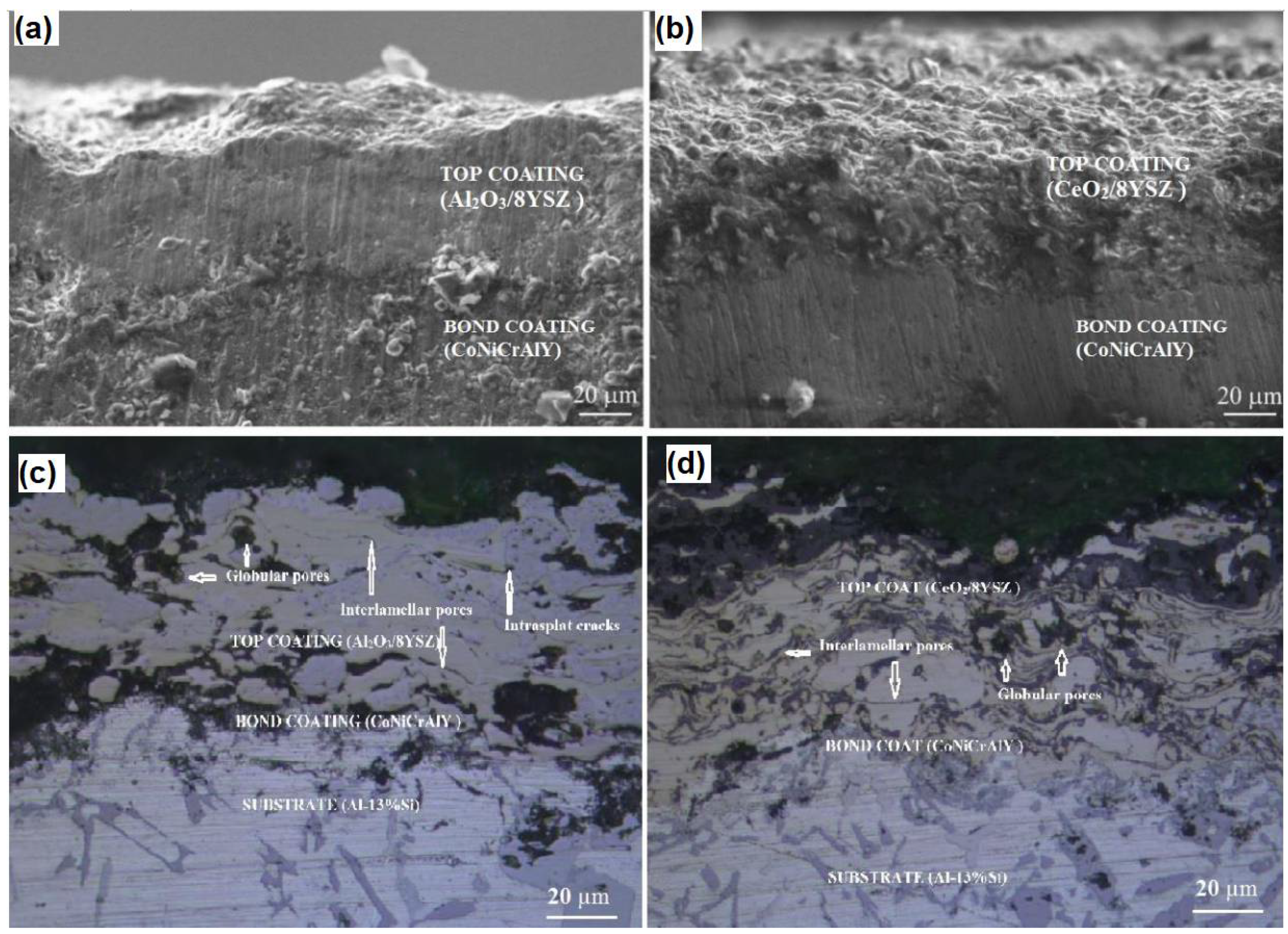
  86. Venkadesan, G.; Muthusamy, J. Experimental investigation of Al2O3/8YSZ and CeO2/8YSZ plasma sprayed thermal barrier coating on diesel engine. Ceram. Int. 2019, 45, 3166–3176. [Google Scholar] [CrossRef]
  87. Song, X.; Lu, J.; Zhang, T.; Ma, J. Sintering behavior and mechanisms of NiO-doped 8 mol% yttria stabilized zirconia. J. Eur. Ceram. Soc. 2011, 31, 2621–2627. [Google Scholar] [CrossRef]
  88. Zhou, L.; Li, X.; He, D.; Guo, W.; Huang, Y.; He, G.; Xing, Z.; Wang, H. Study on Properties of Potassium Sodium Niobate Coating Prepared by High Efficiency Supersonic Plasma Spraying. Actuators 2022, 11, 28. [Google Scholar] [CrossRef]
  89. Wang, Y.-W.; Wang, X.-Y.; Wang, X.-L.; Yang, Y.; Cui, Y.-H.; Ma, Y.-D.; Sun, W.-W. Microstructure and properties of in-situ composite coatings prepared by plasma spraying MoO3–Al composite powders. Ceram. Int. 2020, 47, 1109–1120. [Google Scholar] [CrossRef]
  90. López-Honorato, E.; Dessoliers, M.; Shapiro, I.; Wang, X.; Xiao, P. Improvements to the sintering of yttria-stabilized zirconia by the addition of Ni. Ceram. Int. 2012, 38, 6777–6782. [Google Scholar] [CrossRef]
  91. Yilmaz, O.; Erdogan, M.; Karakaya, I. Combined effects of ALS and SLS on Al2O3 reinforced composite nickel coatings. Surf. Eng. 2018, 36, 477–484. [Google Scholar] [CrossRef]
  92. Noor-A-Alam, M.; Choudhuri, A.; Ramana, C. Effect of composition on the growth and microstructure of hafnia–zirconia based coatings. Surf. Coat. Technol. 2011, 206, 1628–1633. [Google Scholar] [CrossRef]
  93. Wang, N.; Wang, D.P.; Yang, Z.W.; Wang, Y. Interfacial microstructure and mechanical properties of zirconia ceramic and niobium joints vacuum brazed with two Ag-based active filler metals. Ceram. Int. 2016, 42, 12815–12824. [Google Scholar] [CrossRef]
  94. Arantes, V.; Coutinho, R.; Martins, S.; Huang, S.; Vleugels, J. Solid state sintering behavior of zirconia-nickel composites. Ceram. Int. 2019, 45, 22120–22130. [Google Scholar] [CrossRef]
  95. Chen, X.; Zhao, Y.; Gu, L.; Zou, B.; Wang, Y.; Cao, X. Hot corrosion behaviour of plasma sprayed YSZ/LaMgAl11O19 composite coatings in molten sulfate–vanadate salt. Corros. Sci. 2011, 53, 2335–2343. [Google Scholar] [CrossRef]
  96. Park, S.; Kim, J.; Kim, M.; Song, H.; Park, C. Microscopic observation of degradation behavior in yttria and ceria stabilized zirconia thermal barrier coatings under hot corrosion. Surf. Coat. Technol. 2005, 190, 357–365. [Google Scholar] [CrossRef]
  97. Hajizadeh-Oghaz, M.; Razavi, R.S.; Ghasemi, A.; Valefi, Z. Na2SO4 and V2O5 molten salts corrosion resistance of plasma-sprayed nanostructured ceria and yttria co-stabilized zirconia thermal barrier coatings. Ceram. Int. 2016, 42, 5433–5446. [Google Scholar] [CrossRef]
  98. Ahmadi-Pidani, R.; Razavi, R.S.; Mozafarinia, R.; Jamali, H. Evaluation of hot corrosion behavior of plasma sprayed ceria and yttria stabilized zirconia thermal barrier coatings in the presence of Na2SO4+V2O5 molten salt. Ceram. Int. 2012, 38, 6613–6620. [Google Scholar] [CrossRef]
  99. Habibi, M.H.; Wang, L.; Liang, J.; Guo, S.M. An investigation on hot corrosion behavior of YSZ-Ta2O5 in Na2SO4 + V2O5 salt at 1100 °C. Corros. Sci. 2013, 75, 409–414. [Google Scholar] [CrossRef]
  100. Lashmi, P.; Ananthapadmanabhan, P.; Chakravarthy, Y.; Unnikrishnan, G.; Balaji, N.; Aruna, S. Hot corrosion studies on plasma sprayed bi-layered YSZ/La2Ce2O7 thermal barrier coating fabricated from synthesized powders. J. Alloys Compd. 2017, 711, 355–364. [Google Scholar] [CrossRef]
  101. Pakseresht, A.; Javadi, A.; Ghasali, E.; Shahbazkhan, A.; Shakhesi, S. Evaluation of hot corrosion behavior of plasma sprayed thermal barrier coatings with graded intermediate layer and double ceramic top layer. Surf. Coat. Technol. 2016, 288, 36–45. [Google Scholar] [CrossRef]
  102. Batista, C.; Portinha, A.; Ribeiro, R.; Teixeira, V.; de Oliveira, C.A.R. Evaluation of laser-glazed plasma-sprayed thermal barrier coatings under high temperature exposure to molten salts. Surf. Coat. Technol. 2006, 200, 6783–6791. [Google Scholar] [CrossRef]
  103. Soleimanipour, Z.; Baghshahi, S.; Razavi, R.S.; Salehi, M. Hot corrosion behavior of Al2O3 laser clad plasma sprayed YSZ thermal barrier coatings. Ceram. Int. 2016, 42, 17698–17705. [Google Scholar] [CrossRef]
  104. Mishra, N.; Mishra, S.B. Hot corrosion performance of LVOF sprayed Al2O3–40% TiO2 coating on Superni 601 and Superco 605 superalloys at 800 and 900 °C. Bull. Mater. Sci. 2015, 38, 1679–1685. [Google Scholar] [CrossRef]
  105. Thakur, L.; Arora, N. A study of processing and slurry erosion behaviour of multi-walled carbon nanotubes modified HVOF sprayed nano-WC-10Co-4Cr coating. Surf. Coat. Technol. 2017, 309, 860–871. [Google Scholar] [CrossRef]
  106. Afzal, M.A.F.; Kesarwani, P.; Reddy, K.M.; Kalmodia, S.; Basu, B.; Balani, K. Functionally graded hydroxyapatite-alumina-zirconia biocomposite: Synergy of toughness and biocompatibility. Mater. Sci. Eng. C 2012, 32, 1164–1173. [Google Scholar] [CrossRef]
  107. Kaushal, G.; Singh, H.; Prakash, S. Comparative High Temperature Analysis of HVOF-Sprayed and Detonation Gun Sprayed Ni–20Cr Coating in Laboratory and Actual Boiler Environments. Oxid. Met. 2011, 76, 169–191. [Google Scholar] [CrossRef]
  108. Saini, H.; Kumar, D.; Shukla, V. Hot Corrosion behaviour of Nanostructured Cermet based Coatings Deposited by Different Thermal Spray Techniques: A Review. Mater. Today Proc. 2017, 4, 541–545. [Google Scholar] [CrossRef]
  109. Gond, D.; Lalbondre, R.; Puri, D.; Prakash, S. High Temperature Oxidation and Hot Corrosion Behaviour of Yttria- Stabilised Zirconia as Plasma Sprayed Coating in Air and Salt at 900 °C under Cyclic Condition. J. Miner. Mater. Charact. Eng. 2012, 11, 285–302. [Google Scholar] [CrossRef]
  110. Kai, T.; Zhou, X.-L.; Hua, C.; Zhang, J.-S. Oxidation and hot corrosion behaviors of HVAF-sprayed conventional and nanostructured NiCrC coatings. Trans. Nonferrous Met. Soc. China 2009, 19, 1151–1160. [Google Scholar]
  111. Katiki, K.; Yadlapati, S.; Chidepudi, S.N.S.; Manikandan, M.; Arivarasu, M.; Devendranath Ramkumar, K.; Arivazhagan, N. Performance of plasma spray coatings on Inconel 625 in Air oxidation and molten salt environment at 800 °C. Int. J. ChemTech Res. 2014, 6, 2744–2749. [Google Scholar]
  112. Katiki, K.; Yadlapati, S.; Chidepudi, S.N.S.; Hari, P.R. Comparative high temperature corrosion studies on zirconium dioxide coated Inconel 625 in air and molten salt environment. Int. J. ChemTech Res. 2014, 6, 4579–45845. [Google Scholar]
  113. Singh, G.; Goyal, K.; Bhatia, R. Hot corrosion studies of plasma-sprayed chromium oxide coatings on boiler tube steel at 850 C in simulated boiler environment. Iran. J. Sci. Technol. Trans. Mech. Eng. 2018, 42, 149–159. [Google Scholar] [CrossRef]
  114. Hong, C.-Q.; Zhang, X.-H.; Li, W.-J.; Han, J.-C.; Meng, S.-H. A novel functionally graded material in the ZrB2–SiC and ZrO2 system by spark plasma sintering. Mater. Sci. Eng. A 2008, 498, 437–441. [Google Scholar] [CrossRef]
  115. Yongming, L.; Wei, P.; Shuqin, L.; Ruigang, W.; Jianqiang, L. A novel functionally graded material in the Ti–Si–C system. Mater. Sci. Eng. A 2003, 345, 99–105. [Google Scholar] [CrossRef]
  116. Zhang, Z.; Shen, X.; Zhang, C.; Wei, S.; Lee, S.; Wang, F. A new rapid route to in-situ synthesize TiB–Ti system functionally graded materials using spark plasma sintering method. Mater. Sci. Eng. A 2012, 565, 326–332. [Google Scholar] [CrossRef]
  117. Tang, X.; Zhang, H.; Du, D.; Qu, D.; Hu, C.; Xie, R.; Feng, Y. Fabrication of W–Cu functionally graded material by spark plasma sintering method. Int. J. Refract. Met. Hard Mater. 2014, 42, 193–199. [Google Scholar] [CrossRef]
  118. Lee, S.-H.; Tanaka, H.; Kagawa, Y. Spark plasma sintering and pressureless sintering of SiC using aluminum borocarbide additives. J. Eur. Ceram. Soc. 2009, 29, 2087–2095. [Google Scholar] [CrossRef]
  119. Qiao, Z.; Räthel, J.; Berger, L.-M.; Herrmann, M. Investigation of binderless WC–TiC–Cr3C2 hard materials prepared by spark plasma sintering (SPS). Int. J. Refract. Met. Hard Mater. 2013, 38, 7–14. [Google Scholar] [CrossRef]
  120. Demirkıran, A.; Avcı, E. Evaluation of functionally gradient coatings produced by plasma-spray technique. Surf. Coat. Technol. 1999, 116–119, 292–295. [Google Scholar] [CrossRef]
  121. Shanmugavelayutham, G.; Kobayashi, A. Mechanical properties and oxidation behaviour of plasma sprayed functionally graded zirconia–alumina thermal barrier coatings. Mater. Chem. Phys. 2007, 103, 283–289. [Google Scholar] [CrossRef]
  122. Tekmen, C.; Ozdemir, I.; Celik, E. Failure behaviour of functionally gradient materials under thermal cycling conditions. Surf. Coat. Technol. 2003, 174–175, 1101–1105. [Google Scholar] [CrossRef]
  123. Cannillo, V.; Lusvarghi, L.; Sola, A. Production and characterization of plasma-sprayed TiO2–hydroxyapatite functionally graded coatings. J. Eur. Ceram. Soc. 2008, 28, 2161–2169. [Google Scholar] [CrossRef]
  124. Sharma, V.; Kaur, M.; Bhandari, S. Development and Characterization of High-Velocity Flame Sprayed Ni/TiO2/Al2O3 Coatings on Hydro Turbine Steel. J. Therm. Spray Technol. 2019, 28, 1379–1401. [Google Scholar] [CrossRef]
  125. Thakur, L.; Arora, N. An investigation on the development and wear performance of chromium-MWCNTs transformed HVOF sprayed nano-WC-CoCr coatings. Surf. Coat. Technol. 2020, 388, 125610. [Google Scholar] [CrossRef]
  126. Shivamurthy, R.; Kamaraj, M.; Nagarajan, R.; Shariff, S.; Padmanabham, G. Laser surface modification of steel for slurry erosion resistance in power plants. In Laser Surface Modification of Alloys for Corrosion and Erosion Resistance; Woodhead Publishing: Sawston, UK, 2012; pp. 177–287. [Google Scholar] [CrossRef]
  127. Arji, R.; Dwivedi, D.; Gupta, S.R. Some studies on slurry erosion of flame sprayed Ni-Cr-Si-B coating. Ind. Lubr. Tribol. 2009, 61, 4–10. [Google Scholar] [CrossRef]
  128. Chauhan, A.K.; Goel, D.B.; Prakash, S. Erosive wear of a surface coated hydroturbine steel. Bull. Mater. Sci. 2010, 33, 483–489. [Google Scholar] [CrossRef] [Green Version]
  129. Ramesh, C.; Devaraj, D.; Keshavamurthy, R.; Sridhar, B. Slurry erosive wear behaviour of thermally sprayed Inconel-718 coatings by APS process. Wear 2011, 271, 1365–1371. [Google Scholar] [CrossRef]
  130. Grewal, H.S.; Bhandari, S.; Singh, H. Parametric Study of Slurry-Erosion of Hydroturbine Steels with and without Detonation Gun Spray Coatings using Taguchi Technique. Met. Mater. Trans. A 2012, 43, 3387–3401. [Google Scholar] [CrossRef]
  131. Goyal, D.K.; Singh, H.; Kumar, H.; Sahni, V. Slurry erosion behaviour of HVOF sprayed WC–10Co–4Cr and Al2O3+13TiO2 coatings on a turbine steel. Wear 2012, 289, 46–57. [Google Scholar] [CrossRef]
  132. Goyal, D.K.; Singh, H.; Kumar, H.; Sahni, V. Slurry Erosive Wear Evaluation of HVOF-Spray Cr2O3 Coating on Some Turbine Steels. J. Therm. Spray Technol. 2012, 21, 838–851. [Google Scholar] [CrossRef]
  133. Bhandari, S.; Singh, H.; Kumar, H.; Rastogi, V. Slurry erosion performance study of detonation gun-sprayed WC-10Co-4Cr coatings on CF8M steel under hydro-accelerated conditions. J. Therm. Spray Technol. 2012, 21, 1054–1064. [Google Scholar] [CrossRef]
  134. Wang, Y.; Li, M.X.; Suo, H.L. Mechanical properties of YSZ thermal barrier coatings with segmented structure. Surf. Eng. 2012, 28, 329–332. [Google Scholar] [CrossRef]
  135. Karaoglanli, A.C.; Turk, A.; Ozdemir, I. Effect of sintering on mechanical properties of cold sprayed thermal barrier coatings. Surf. Eng. 2016, 32, 686–690. [Google Scholar] [CrossRef]
  136. Shang, F.L.; Zhang, X.; Guo, X.C.; Zhao, P.F.; Chang, Y. Determination of high temperature mechanical properties of thermal barrier coatings by nanoindentation. Surf. Eng. 2014, 30, 283–289. [Google Scholar] [CrossRef]
  137. Singh, J.; Thakur, L.; Angra, S. A study of tribological behaviour and optimization of WC-10Co-4Cr Cladding. Surf. Eng. 2020, 37, 70–79. [Google Scholar] [CrossRef]
  138. Keyvani, A.; Bahamirian, M. Hot corrosion and mechanical properties of nanostructured Al2O3/CSZ composite TBCs. Surf. Eng. 2017, 33, 433–443. [Google Scholar] [CrossRef]
  139. Liu, X.-B.; Kang, J.-J.; Yue, W.; Fu, Z.-Q.; Zhu, L.-N.; She, D.-S.; Liang, J.; Wang, C.-B. Performance evaluation of HVOF sprayed WC-10Co4Cr coatings under slurry erosion. Surf. Eng. 2018, 35, 816–825. [Google Scholar] [CrossRef]
  140. Hong, S.; Wu, Y.P.; Gao, W.W.; Wang, B.; Guo, W.M.; Lin, J.R. Microstructural characterisation and microhardness distribution of HVOF sprayed WC–10Co–4Cr coating. Surf. Eng. 2013, 30, 53–58. [Google Scholar] [CrossRef]
  141. Upadhyaya, R.; Tailor, S.; Shrivastava, S.; Modi, S.C. High performance thermal-sprayed WC-10Co-4Cr coatings in narrow and complex areas. Surf. Eng. 2017, 34, 412–421. [Google Scholar] [CrossRef]
  142. Borkar, T.; Harimkar, S. Microstructure and wear behaviour of pulse electrodeposited Ni–CNT composite coatings. Surf. Eng. 2011, 27, 524–530. [Google Scholar] [CrossRef]
  143. Ramalingam, S.; Balakrishnan, K.; Shanmugasamy, S.; Subramania, A. Electrodeposition and characterisation of Cu–MWCNTs nanocomposite coatings. Surf. Eng. 2016, 33, 369–374. [Google Scholar] [CrossRef]
  144. La Barbera-Sosa, J.G.; Santana, Y.Y.; Caro, J.; Chicot, D.; Lesage, J.; Staia, M.H.; Puchi-Cabrera, E.S. Mechanical properties of WC coatings evaluated using instrumented indentation technique. Surf. Eng. 2014, 30, 498–510. [Google Scholar] [CrossRef]
  145. Santana, Y.Y.; La Barbera-Sosa, J.G.; Bencomo, A.; Lesage, J.; Chicot, D.; Bemporad, E.; Puchi-Cabrera, E.S.; Staia, M.H. Influence of mechanical properties of tungsten carbide–cobalt thermal spray coatings on their solid particle erosion behaviour. Surf. Eng. 2012, 28, 237–243. [Google Scholar] [CrossRef]
  146. Lavasani, H.Q.; Valefi, Z.; Ehsani, N.; Masoule, S.T. Comparison of the effect of sintering on the microstructure, micro hardness and phase composition of conventional and nanostructured YSZ TBCs. Ceram. Int. 2017, 43, 12497–12504. [Google Scholar] [CrossRef]
  147. Zhou, F.; Deng, C.; Wang, Y.; Liu, M.; Wang, L.; Wang, Y.; Zhang, X. Characterization of multi-scale synergistic toughened nanostructured YSZ thermal barrier coatings: From feedstocks to coatings. J. Eur. Ceram. Soc. 2020, 40, 1443–1452. [Google Scholar] [CrossRef]
  148. Demir, H.; Cosgun, A.E. The Effect on Energy Efficiency of Yttria-Stabilized Zirconia on Brass, Copper and Hardened Steel Nozzle in Additive Manufacturing. Coatings 2022, 12, 690. [Google Scholar] [CrossRef]
  149. Demir, H. The Effects on Thermal Efficiency of Yttria-Stabilized Zirconia and Lanthanum Zirconate-Based Thermal Barrier Coatings on Aluminum Heating Block for 3D Printer. Coatings 2021, 11, 792. [Google Scholar] [CrossRef]
  150. Veselý, P. Nozzle temperature effect on 3D printed structure properties. In Proceedings of the Zborník Príspevkov z Medzinárodnej Konferencie Elektrotechnológia, Zuberec, Slovakia, 21–23 May 2019; pp. 126–131. [Google Scholar]
  151. Demir, H.; Coşgun, A.E. 3B Yazıcılarda Kullanılan Farklı Tip Ekstüderlerin ANSYS Programı ile Termal Analizlerinin Gerçekleştirilmesi. Düzce Üniversitesi Bilim Ve Teknol. Derg. 2021, 10, 275–284. [Google Scholar] [CrossRef]
  152. Tishkevich, D.I.; Grabchikov, S.S.; Tsybulskaya, L.S.; Shendyukov, V.S.; Perevoznikov, S.S.; Trukhanov, S.V.; Trukhanova, E.L.; Trukhanov, A.V.; Vinnik, D.A. Electrochemical deposition regimes and critical influence of organic additives on the structure of Bi films. J. Alloys Compd. 2018, 735, 1943–1948. [Google Scholar] [CrossRef]
  153. Tishkevich, D.I.; Grabchikov, S.S.; Lastovskii, S.B.; Trukhanov, S.V.; Zubar, T.I.; Vasin, D.S.; Trukhanov, A.V. Correlation of the synthesis conditions and microstructure for Bi-based electron shields production. J. Alloys Compd. 2018, 749, 1036–1042. [Google Scholar] [CrossRef]
  154. Guo, C.; Zhang, Z.; Wu, Y.; Wang, Y.; Ma, G.; Shi, J.; Zhong, Z.; Hong, Z.; Jin, Z.; Zhao, Y. Synergic realization of electrical insulation and mechanical strength in liquid nitrogen for high-temperature superconducting tapes with ultra-thin acrylic resin coating. Supercond. Sci. Tech. 2022, 35, 075014. [Google Scholar] [CrossRef]
  155. Tishkevich, D.I.; Zubar, T.I.; Zhaludkevich, A.L.; Razanau, I.U.; Vershinina, T.N.; Bondaruk, A.A.; Zheleznova, E.K.; Dong, M.; Hanfi, M.Y.; Sayyed, M.I.; et al. Isostatic Hot Pressed W–Cu Composites with Nanosized Grain Boundaries: Microstructure, Structure and Radiation Shielding Efficiency against Gamma Rays. Nanomaterials 2022, 12, 1642. [Google Scholar] [CrossRef]
  156. Singh, H.; Prakash, C.; Singh, S. Plasma spray deposition of HA-TiO2 on β-phase Ti-35Nb-7Ta-5Zr alloy for hip stem: Characterization of bio-mechanical properties, wettability, and wear resistance. J. Bionic Eng. 2020, 17, 1029–1044. [Google Scholar] [CrossRef]
  157. Singh, S.; Prakash, C.; Singh, H.J.S.; Technology, C. Deposition of HA-TiO2 by plasma spray on β-phase Ti-35Nb-7Ta-5Zr alloy for hip stem: Characterization, mechanical properties, corrosion, and in-vitro bioactivity. Surf. Coat. Technol. 2020, 398, 126072. [Google Scholar] [CrossRef]
  158. Prakash, C.; Kansal, H.K.; Pabla, B.; Puri, S. Powder mixed electric discharge machining: An innovative surface modification technique to enhance fatigue performance and bioactivity of β-Ti implant for orthopedics application. J. Comput. Inf. Sci. Eng. 2016, 16, 041006. [Google Scholar] [CrossRef]
  159. Singh, H.; Kumar, R.; Prakash, C.; Singh, S. HA-based coating by plasma spray techniques on titanium alloy for orthopedic applications. Mater. Today Proc. 2021, 50, 612–628. [Google Scholar] [CrossRef]
Figure 1. (A) Schematic diagram of a gas turbine, (B) Blade of the turbine and (C) cross-section TBC system [6].
Coatings 12 01318 g001
Figure 2. Year-wise data published on thermal barrier coatings.
Coatings 12 01318 g002
Figure 3. Schematic of the Thermal Barrier coating (TBC) part in thermal gradient and air–cooling.
Coatings 12 01318 g003
Figure 4. (a) FESEM polished cross-section micrographs of As-sprayed TBC with traditional or Conventional YSZ coating and (b) Nanostructure YSZ coating [13].
Coatings 12 01318 g004
Figure 5. Wide classification of the coating process and methods used for material deposition.
Coatings 12 01318 g005
Figure 6. FE-SEM images show the morphology of the (a) NiAl, (b) YSZ, (c) CeO2and (d) Al2O3 feedstock powder.
Coatings 12 01318 g006
Figure 7. Low magnification FE-SEM images show the plasma-sprayed cross-sectional surface (a) NiAl/YSZ, (b) NiAl/YSZ/Al2O3 and (c) NiAl/YSZ/Al2O3/CeO2 [36].
Coatings 12 01318 g007
Figure 8. FE-SEM micrograph images of (a) NiAl/YSZ, (b) NiAl/YSZ/Al2O3 and (c) NiAl/YSZ/Al2O3/CeO2, based coating structure exhibiting the micro-cracks, partially melted (PM), fully melted (FM) region [36].
Coatings 12 01318 g008
Figure 9. The plasma spraying parametersfor the top coat’s second stage.
Coatings 12 01318 g009
Figure 10. Themost important controller parameters used in APS [41].
Coatings 12 01318 g010
Figure 11. FE-SEM images show the functional zones of the FGC technique [47].
Coatings 12 01318 g011
Figure 12. The purposes of the FGC mechanism: (a) thermal diffusivity, (b) thermal conductivity, and (c) the correlation between porosity and thermal conductivity in atmospheric temperature [48].
Coatings 12 01318 g012
Figure 13. Display to deposits system used in the SPS method [59].
Coatings 12 01318 g013
Figure 14. Schematic view of a Solution Precursor Plasma Spray system with radial injection.
Coatings 12 01318 g014
Figure 15. The SPPS TBCs have unique microstructural characteristics: (a) small splat area, and (b) stress reduced by introducing vertical cracks inside the coating [64,65].
Coatings 12 01318 g015
Figure 16. Cross-sectional SEM images of a YSZ thermal barrier coating fabricated by PS-PVD [77].
Coatings 12 01318 g016
Figure 17. The importance and requirement of Thermal Barrier Coating (TBC) in surface engineering applications.
Coatings 12 01318 g017
Figure 18. Effect of corrosion on (a) corrugated plate and (b) positioning plate of air preheater (lower portion) [80].
Coatings 12 01318 g018
Figure 19. Classification of hot corrosion based on temperature.
Coatings 12 01318 g019
Figure 20. Mechanism of hot corrosion and stages.
Coatings 12 01318 g020
Figure 21. Preventative strategies to combat the hot-corrosion effects at high temperatures.
Coatings 12 01318 g021
Figure 22. Cross-sectional morphologies of as-sprayed TBCs: (a) Al2O3/8YSZ TBCs and (b) CeO2/8YSZ TBCs; (c) Al2O3/8YSZ TBCs backscattered election images; (d) CeO2/8YSZ TBCs backscattered electron images [86].
Coatings 12 01318 g022
Figure 23. Morphology of indentation of (a) nanostructure and (b) traditional ceramic coatings after application (5 kgf) [148].
Coatings 12 01318 g023
Table 1. The plasma spraying parametersfor the top coat’s first stage.
Substrate MaterialPowder Feed Rate (g/min)Current (A)Voltage (V)Power (kW)Stand-Off Distance (mm)
stainless steel [34]20–4060066–68-100
IN-738LC [35]256006036150
IN-738LC [40]38600-64100
Amdry 995C [37]6060065-120
204B-NS [37]4060065-130
stainless steel [38]306006350100
stainless steel [38]356006742120
Inconel 718 [39]35–406006035130
Table 2. Hot corrosion behavior of TBC-based YSZ coatings in the presence of corrosive salts and infiltration mode.
Substrate
Material
Corrosive Salt Used (wt.%)Composite MaterialsTemperature and Time of ExposureTechniqueInfiltration of Molten Salt in Coating
Ni-based superalloy50 Na2SO4 + 50 V2O5YSZ [95](950 °C, 60 h)APSCompletely
Ni-based superalloyNaVO3YSZ [96](900 °C, 300 h)APSCompletely
Ni-based superalloy45 Na2SO4 + 55 V2O5YSZ + CeO2 [97](1000 °C, 300 h)APSPartially
Inconel 738LC superalloy55 V2O5 + 45 Na2SO4YSZ + CeO2 [98](1000 °C, 30 h)APSPartially
Superalloy (Ni3Al) plates45 Na2SO4 + 55 V2O58YSZ + Al2O3 [99](900 °C, 380 h)APSPartially
Ni-based superalloyNaVO3YSZ + CeO2 [96](900 °C, 300 h)APSPartially
Ni-based superalloy50 Na2SO4 + 50 V2O5YSZ/LaMgAl11O19 [95](950 °C, 60 h)APSPartially
Inconel 738LC superalloy50 Na2SO4 + 50 V2O5YSZ-Ta2O5 [100](1100 °C, 4 h)SinteringPartially
Nickel superalloy45 Na2SO4 + 55 V2O5YSZ/La2Ce2O7 [101](910 °C, 30 h)APSPartially
Inconel 738LC, Ni-15Cr-8.5Co45 Na2SO4 + 55 V2O5YSZ/Al2O3 [102](1050 °C, 40 h)APSPartially
Inconel 738 LC superalloy60 V2O5 + 40 Na2SO4YSZ [103](1000 °C, 100 h)APS + lasercladdingCompletely
Inconel 73855 V2O5 + 45 Na2SO4YSZ/Al2O3 [104](1000 °C, 30 h)APS + lasercladdingPartially
Table 3. Thermal oxidation performance obtained from different coating materials.
YearSubstrate MaterialCoating MaterialCoating MethodTemperature (°C)Weight Gain of the Coated Substrate (mg/cm2)Weight Gain of the Uncoated Substrate (mg/cm2)Percentage Drop after Hot Oxidation
2015SC 605Al2O3-40% TiO2 [105]low-velocity oxy-fuel spray80049.1252.795.64
2011T-22Ni-20Cr [108]Detonation Gun spray80016.146.5465.58
2006T-22Ni-20Cr [109]High-velocity oxy-fuel spray (HVOF)9008.2614.9944.98
2012T-91Yttria-stabilized zirconia (YSZ) [110]Plasma spray (PS)8008.3169.173.61
2014ASTM1020 SteelNiCrC nano [111]HVOF5500.1212.9899.24
NiCrC Conventional [111]HVOF5500.2912.9997.69
NiCrC nano [111]HVOF6501.134.197.07
NiCrC Conventional [111]HVOF6501.5134.195.6
2014INCONEL 625Al2O3-TiO2 [112]Plasma spray (PS)80051566.68
2014INCONEL 625ZrO2 [113](PS)8001.121592.68
2017T22CrO3 [114](PS)80050.9465.1721.85
Table 4. Hardness and toughness values obtained from different coating materials in TBC.
YearSubstrate
Metal
Coating MaterialFabrication ProcessHardness Value (HV)Toughness (MPa√m)
2008MSZrB2–SiC/ZrO2
[115]
Suspension plasma spraying (SPS)20–18 GPa
2003MSAl2O3–Ti3SiC2
[116]
(SPS)4–17 GPa
2013SS-316TiB–Ti
[117]
(SPS)5.8–17 GPa
2012SS-316HAp–Al2O3–YSZ
[107]
(SPS)6–13.9 GPa
2014IN-738LCW–Cu
[118]
(SPS)4–5 GPa1.4 ± 0.11
2009IN-800LCSiC–Al3BC3
[119]
(SPS)18.5–26.4 GPa1.6 ± 0.09
2013IN-738LCWC–TiC–Cr3C2
[120]
(SPS)18.4–23.2 GPa0.9 ± 0.12
1999SS-304NiCrAl-MgZrO3
[121]
Plasma spray (PS)900–350 BHN
2007IN-625LCZrO2–Al2O3
[122]
(PS)1170–870
2003SS-304NiCrAl/MgZrO3
[123]
(PS)150–220
2008AISI-410TiO2–HAp
[124]
(PS)363.9–513.7
2019CA6NMNi-40TiO2
[125]
(HVFS)605 ± 371.8 ± 0.2
Ni-20TiO2 + 20Al2O3
[125]
(HVFS)585 ± 33 1.6 ± 0.2
2016SS-304WC-10Co-4Cr nanostructure
[106]
HVOF sprayed1696 ± 462.01 ± 0.04
WC-10Co-4Cr conventional
[106]
HVOF sprayed1147 ± 503.61 ± 0.31
2020SS-304MWCNTs reinforced with nano-WC-Co-Cr
[126]
HVOF sprayed1530 ± 1439.14 ± 1.30
2012 13Cr–4NiColmonoy 88 and stellite-6
[127]
Laser surface modification674–800
2006MS Ni-Cr-Si-B
[128]
Flame sprayed280
201021Cr–4Ni–N steelstellite-6
[129]
D-Gun1098
Cr3C2-NiCr [129]D-Gun824
WC-Co-Cr [129]D-Gun990
2011MSInconel-718
[130]
APS process340
201213Cr4Ni and 16Cr5Ni steelsWC-Co-Cr on 13Cr4Ni
[131]
D-Gun1401
WC-Co-Cr on 16Cr5Ni
[131]
D-Gun1422
2012CF8MWC-10Co-4Cr
[132]
D-Gun1160
Al2O3 + 13TiO2
[132]
D-Gun830
2012CF8M and CA6NMCr2O3 on CF8M
[133]
HVOF sprayed1200
Cr2O3 on CA6NM [133] 1400
2012CF8MWC-10Co-4Cr
[134]
D-Gun1120
2012Ni based superalloyZrO2–8 mass-%Y2O3 [135](APS)72 GPa2.0 ± 0.3
2016IN-718LCYSZ (ZrO2 + Y2O3) [136](APS)680
IN-718LCYSZ (ZrO2 + Y2O3) [136]CGDS740
2014IN-718LC8YSZ [137](APS)58.04 GPa1.58 ± 0.15
2020Stainless steelWC-10Co-4Cr [138]TIG welding713.13–879.513.84 ± 0.11
2017IN-738LCAl2O3/CSZ [139](APS)172.05 GPa
201935CrMoWC-10Co4Cr [140]HVOF1316 ± 45 7.11 ± 0.10
2014AISI 1045 steelWC–10Co–4Cr [141]HVOF983
2018CA6NM steelWC-10Co-4Cr [142]High-Velocity Oxy Liquid Fuel (HVOLF)1402 ± 16
2011Stainless steelNi [143]Electrodeposition320 ± 15
Ni–CNT [143]Electrodeposition580 ± 15
2017Pure BrassCu–MWCNTs [144]Electrodeposition335
2014SAE 1045 steelWC–10Co–4Cr [145]HVOF11.1 GPa
WC–12Co [145]HVOF9.3 GPa
2012SAE 1045 steelWC–10Co–4C [146]HVOF261 ± 101.42 ± 0.80
WC–12Co [146]HVOF254 ± 124.56 ± 0.90
2017IN-738LC8YSZ conventional [147](APS)421
8YSZ nanostructured [147](APS)327
Publisher’s Note: MDPI stays neutral with regard to jurisdictional claims in published maps and institutional affiliations.

