Article

Ferroelectric B-Site Modified Bismuth Lanthanum Titanate Thin Films for High-Efficiency PV Systems

1
Department of Electrical Engineering, Gachon University, Seongnam 13120, Korea
2
School of Intelligent Mechatronics Engineering, Sejong University, Seoul 05006, Korea
*
Authors to whom correspondence should be addressed.
These authors contributed equally to this work.
Coatings 2022, 12(9), 1315; https://doi.org/10.3390/coatings12091315
Submission received: 12 August 2022 / Revised: 2 September 2022 / Accepted: 7 September 2022 / Published: 9 September 2022
(This article belongs to the Special Issue Optical Thin Film and Photovoltaic (PV) Related Technologies)

Abstract

:
Over the past decades, ferroelectric photovoltaic (FE-PV) systems, which use a homogenous ferroelectric material as a light-absorbing layer, have been studied using ferroelectric oxides. The PV activity of materials can be enhanced by adjusting the bandgap of materials, and it would have a large effect on the ferroelectric complex oxides. This phenomenon in epitaxial thin films of ferroelectric complex oxide, Bi3.25La0.75Ti3O12 (BLT), Fe- and Co-doped films were observed. Compared with undoped BLT, Co-(BLCT) doping and Fe and Co combined (BLFCT) doping resulted in the gradual reduction in the bandgap and efficient visible light absorption. The reduction in the bandgap to 11.4% and 18.1% smaller than the experimentally measured Eg of the bismuth titanate-based film using a simple Fe- and Co-doping method was performed, while maintaining ferroelectricity by analyzing the BLCT and BLFCT films based on polarization loops, and the temperature range of the out-of-plane lattice parameters and the photocurrent density of the BLFCT film was 32.2 times higher than that of the BLT film, which was caused by the decrease in the bandgap. This simple doping technique can be used to tune additional wide-bandgap complex oxides so that they can be used in photovoltaic energy conversion or optoelectronic devices.

1. Introduction

Solar energy is one of the most abundant and reliable sources of energy and can be used to replace fossil fuels [1,2]. The photovoltaic (PV) effect is a process to generate electricity by transforming incoming photons into flowing free-charge carriers using solar energy. Since Albert Einstein discovered the PV phenomenon, PV technology has been enhanced for more than a century. After decades of study and development, commercial crystalline silicon solar panels are still expensive compared with inexpensive fossil fuels [3]. Second- and third-generation PV cells, e.g., thin-film amorphous silicon solar cells, are being developed to reduce the cost to harvest energy from PV cells.
The ferroelectric PV phenomenon, which may generate a steady PV response (photocurrent and photovoltage) along the polarization direction, was identified approximately half a century ago in several ferroelectric materials without centrosymmetry [4]. The ferroelectric photovoltaic effect is caused by spontaneous polarization in ferroelectric materials [5]. The direction of the photocurrent can be altered in the presence of an electric field by changing the direction of the spontaneous polarization of the ferroelectric material, which is a unique property of ferroelectric optoelectronic devices. To date, the PV effect in barium titanate (BaTiO3, referred to as BTO) [6], lithium niobate (LiNbO3) [7], lead zirconate titanate (Pb(Zr, Ti)O3 or PZT) [8], and bismuth ferrite (BiFeO3 or BFO) [9] has been studied.
Reduction in the bandgap is one of the key factors for the ferroelectric PV. While the non-ferroelectric silicon with a bandgap of 1.1 eV can absorb the spectrum below 1130 nm, the bandgaps of well-known ferroelectric and multiferroic materials (e.g., BaTiO3, BiFeO3, LiNbO3, and Pb(Zr, Ti)O3 crystals) exceed 3 eV. As a result, they can only absorb most of the ultraviolet (UV) radiation. However, UV light (<400 nm) contributes to 3.5% of the overall radiation intensity from the sun, while visible light (400–700 nm) accounts for 42%. To achieve an enhanced photocurrent, ferroelectric materials with narrow Eg (bandgap energy) used for high light absorption (including visible light) are required. The large bandgap represents the reduction in the spectral range that can be absorbed. Only a small part of the ultraviolet radiation can be absorbed.
Various regulation methods were adapted to oxide thin films for the change of the bandgap and the adjustment of the photovoltaic performance. For example, the solution-drop epitaxy method to embed the crystal in the perovskite matrix to improve the generation of luminescent quantum was evaluated [10]; applying a magnetic field to the ferroelectric thin film, the ferroelectric photovoltaic effect The modulation method of the phase structure, which is changed by the magneto-induced in situ stress, was also studied [11]; the use of the lead-free solid solution film BiMnO3 to modify the bandgap to improve the photovoltaic response is also gradually widely used [12].
It is known that transition metal dopants can affect optical properties and their PV performance. Based on the calculation of previous literatures [13,14] and our previous report [15], a doping approach based on theoretical research to study the tuning of the bandgap on ferroelectric Bi3.25La0.75Ti3O12 (BLT) films was used. For instance, despite the arbitrary doping of B sites in the ABO3 type perovskite structure, the photocurrent density of the BLCT film improves by a factor of 6 compared with that of the BLT film while preserving ferroelectricity, unlike that of superlattices. Furthermore, the photocurrent density of the BLFCT film is 32.2-fold larger than that of the BLT film. It can confirm a significant reduction in the bandgap after simple doping based on the considerable increase in the photocurrent density of the BLCT and BLFCT films. In this study, bandgap-tuned Co-doped BLT (Bi3.25La0.75Co1Ti2O12, BLCT) and Fe- and Co-doped BLT (Bi3.25La0.75Fe0.25Co0.75Ti2O12, BLFCT) films were fabricated by radio frequency sputtering (RF sputtering). The bandgaps of BLCT and BLFCT films were reduced to 2.25 and 2.08 eV, respectively. For BLFT and BLFCT films with a reduced energy band, more of the spectrum, including ultraviolet light, can be absorbed, so that more photons can enter the film to excite electrons and improve the efficiency of photocurrent or photovoltage.

2. Experiment Detail

2.1. Sample Fabrication Process

All thin-film deposition targets were made from the following binary oxide powders as raw materials: Bi2O3 (99.9%, Kojundo Chemical Company, Saitama, Japan), TiO2 (99.99%, Kojundo Chemical Company), La2O3 (99.99%, Kojundo Chemical Company), Fe2O3 (99.9%, Kojundo Chemical Company), and Co3O4 (99.99%, Kojundo Chemical Company). The ratio of the transition metal dopant, Co, Fe in doped targets was considered to enhance bandgap tuning. Doping ratios were Bi3.25La0.75Co1Ti2O12 and Bi3.25La0.75Fe0.25Co0.75Ti2O12 based on our previous studies [13]. The undoped BLT, doped BLCT, and doped BLFCT powders were completely combined during the milling process for 24 h in stoichiometric proportions, dried in an oven at 80 °C, and calcined in air for 10 h at 800 °C. The calcined powders were pressed into the target for 5 min at 50 MPa and sintered for 24 h at 1000 °C as shown in Figure 1.
Epitaxial BLT, BLCT, and BLFCT films (d = 250 nm each) were deposited using RF magnetron sputtering at an operating repetition rate of 135 mTorr and a RF power of <50 W on the (001)-oriented Nb-SrTiO3 substrate under 40-sccm argon gas flow. To ensure deposition efficiency, the lowest operating pressure (50 MPa) at which glow discharge could occur was considered, and the substrate temperature of all films was 750 °C as shown in Figure 1.

2.2. Characteristics Measurements

X-ray diffraction (XRD, SmartLab, Rigaku, Tokyo, Japan) examined structural characteristics using Cu Kα radiation (λ = 1.54056 Å, 40 kV, 40 mA). Field Emission Scanning Electron Microscope (FE-SEM, Hitachi, S-4700, Tokyo, Japan) and atomic force microscopy (AFM) analyzed the microstructure of the thin films (Park NX10, Park Systems, Suwon, Korea). A ferroelectric tester (Precision Multiferroic, Radiant Technologies Inc., Albuquerque, NM, USA) was used to measure polarized hysteresis (P-E) loops. BLT, BLCT, and BLFCT films were fabricated on single crystal SrTiO3- (110) doped 0.5 wt% Nb substrates as bottom electrodes to evaluate polarized hysteresis loops. Photolithography was used to etch the upper electrode, and radio frequency (RF) sputtering was used to deposit the Pt top electrode (diameter of 150 nm) on the films. In the c-plane orientation, the polarization value and the P-E loops of the films were evaluated between the bottom (Nb-doped SrTiO3) and top electrode (Pt). An ultraviolet-visible (UV-Vis) near-infrared (NIR) absorption spectrometer (Agilent 8453, Agilent Technologies, Santa Clara, CA, USA) was used to examine the optical characteristics of the films under light within a wavelength range of 385–800 nm. To prevent the modification of the absorption coefficient caused by the thickness effect, a comparable thickness for all three films (pristine BLT, BLCT, and BLFCT) was considered. A source meter (Source Meter 2410, Keithley, Cleveland, OH, USA) was used to measure photocurrent density. A 100W solar simulator was used for measurement under light illumination (K3000, McScience, Suwon, Korea). The sputtering was used to deposit Pt circular electrodes (thickness = 100 nm) with a spacing of 0.95 mm on the film surface. The photocurrent density of the film was observed between the Pt electrodes after the 2 points were in contact. The interesting area between the two electrodes was 4.86 × 10⁻⁴ cm2, the solar light spot size was 15 × 15 cm2, and the photocurrent was taken 10 s per one time.

3. Results and Discussion

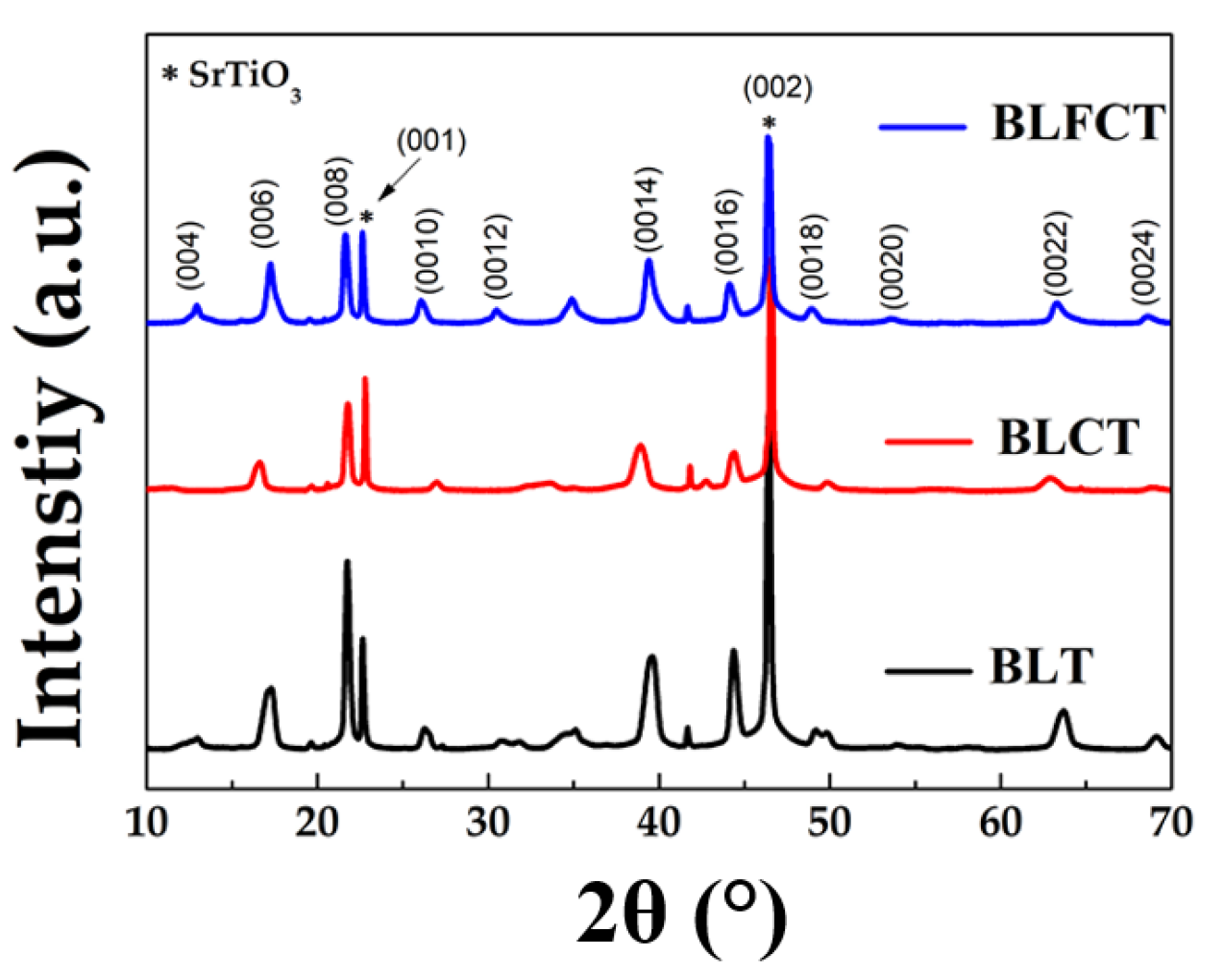
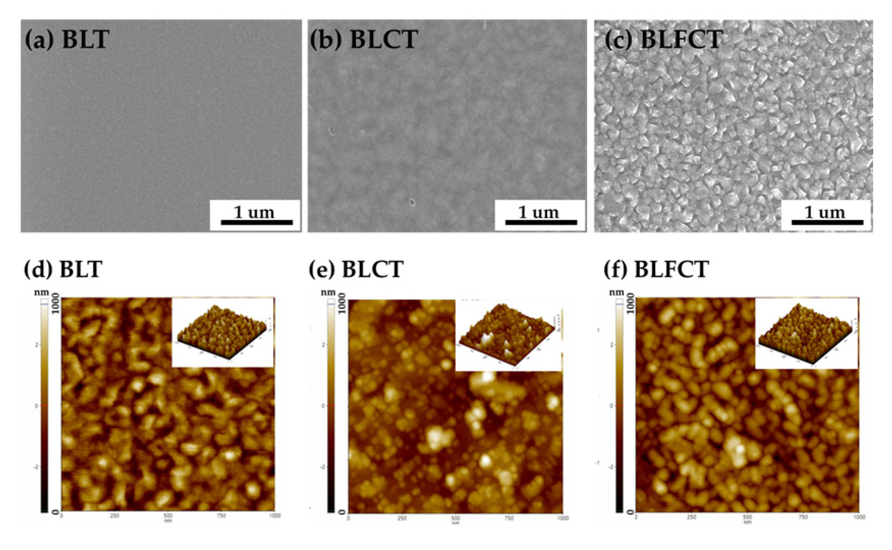
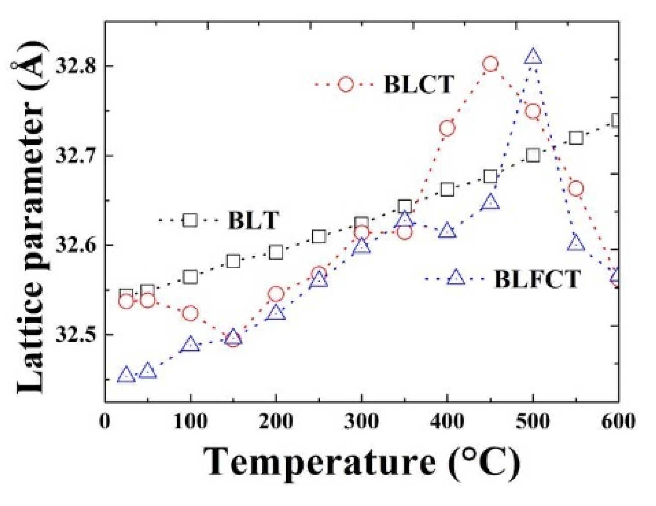
3.1. Film’s Crystal Structure and Ferroelectricity

Figure 2 shows XRD patterns measured in 2-theta scans of BLT, BLCT, and BLFCT thin films grown on a (001)-oriented Nb-doped SrTiO3 (Nb-STO) substrate. Even though the films have layered crystallographic structures, all films were grown epitaxially, and it was confirmed by using XRD [16,17]. All the thin films were formed along the (00l) direction, and BLT crystal structures of the BLCT and BLFCT films were preserved according to the XRD patterns. This implies that doping Co and Fe into the BLT structure does not result in additional phases, and dopants can be changed. Furthermore, (008) exhibited crisp and powerful diffraction peaks, indicating extreme crystallinity. No impurity peaks were observed owing to the exceptional purity of the thin films. Moreover, diffraction peaks, e.g., BLT (008), gradually shifted to a higher diffraction angle with the doping of Co and Fe atoms, implying successful alloying in the BLFCT thin films.
An increase in the dopant would induce enhancement of light absorption and PV performance. However, the heavy doping at the B-site would cause a change in crystal symmetry. That can cause a complete loss of ferroelectricity because the property can exist only with the noncentrosymmetric crystal structure. The concentration of the dopant was optimized to avoid this situation. Based on XRD results, it was confirmed that all grown films had the same crystallographic symmetry with and without doping atoms.
Figure 3a–c show the surface and cross-sectional SEM results of all the prepared BLT thin films on the Nb-SrTiO substrate. This implies that the thin film surfaces were relatively dense, and the grain size gradually increased with the doping of Co and Fe; the grain growth kinetics were enhanced owing to the doping of Co and Fe (Figure 3a). Few well-defined grains and nanoscale pores were observed. Figure 3c,d show SEM images of the BLT films doped with Fe and Co under the same RF sputtering conditions. In the second case, both BLT films were deposited using the same deposition parameters with an increase in the grain size. Figure 3c shows a distinct granularity, which is caused by the growth of BLT caused by the doping of Fe and Co on the Nb-SrTiO3 substrates. Although the peak of CoFe2O4 was not evident in XRD, it was observed on the SEM map of BLFCT. Several diverse domains appeared, which is similar to previously reported results. Therefore, the probability this is caused by the appearance of the CoFe2O4 phase [15] is expected. To assess the large-area uniformity and stability of the thin film on the Nb-SrTiO3 substrate, AFM imaging was performed at multiple locations of the sample. AFM images (Figure 3d,e) show highly ordered stripes on the as-deposited BLT, BLCT, and BLFCT thin films over the entire sample, similar to the SEM images discussed previously. In particular, the root-mean-square roughness of the stripes is 0.8, 3.8, and 3.9 nm; this implies that BLT, BLCT, and BLFCT thin films possess a morphology of smooth, dense, and crack-free surfaces, which agrees with the SEM images.
The polarization of the BLT and BLCT films as functions of the electric field (Figure 4a) was measured. The films were fabricated on the Nb-SrTiO (001) substrate enclosed with the Nb(0.5 wt%) bottom electrode to accurately analyze ferroelectricity, because the polarization direction of the BLT film was in-plane, and it became difficult to check the ferroelectricity of the film along the direction of c-axis [18]. As shown in Figure 4a, the BLT and BLCT films show a ferroelectric response. Based on the analysis of the previous results [13,15], they used a BLFCT (Fe:Co of 50%:50%) target, and CoFe2O4 and BLT were separated from each other in the films obtained using pulsed laser deposition (PLD), and ferroelectric properties were maintained. However, the BLFCT (Fe:Co 25%:75%) films, also deposited using PLD, exhibited weak ferroelectricity. Unlike the films sputtered using PLD, film growth on the substrate differed depending on the method of film sputtering, especially in the case of the BLT film doped with multiple elements, which has resulted in various morphologies. This may be one of the reasons why BLFCT (Fe:Co of 25%:75%) films in this study do not exhibit ferroelectricity [15,19,20]. To summarize, with hysteresis polarization loops, BLT and BLCT films maintain ferroelectricity at different frequencies (Figure 4b,c).
Figure 4b shows hysteresis polarization loops in which the BLT film sustains ferroelectricity at various frequencies. The hysteresis loop shifts to the positive side of the electric field axis. This phenomenon is known as imprinting and may cause the capacitor to fail. Ti and Bi ions are known to be unstable. Bi ions readily evaporate, but Ti ions can exist as Ti3+ and Ti4+, and defects, e.g., bismuth and oxygen vacancies, are the most mobile charges and play a key role in conduction and polarization fatigue. At the grain boundaries and film–electrode interfaces, oxygen vacancies coupled with bismuth vacancies (Bi+3-O−2) can increase local stoichiometry deviations and change the form of the hysteresis loop [14]. The grain border percentage decreases as the Co-doping level increases, limiting the likelihood of space-charge trapping at the grain boundaries. This mark was eliminated by doping BLT films with Co.
In general, photogenerated carrier separation and light absorption are directly connected to the PV performance in FE-PV materials. The bandgap is the primary determinant of light absorption. As a result, by modifying the doping degree of the films, the mechanism of the PV effect was further examined, with the doping dependence of the bandgap being explored initially. Figure 5a shows the light absorption of BLT thin films with different doping concentrations. Due to the influence of the black Nb-STO substrate, the absorption edge here is not particularly obvious. The intensity of light absorption gradually increases with doping, indicating that the doping of Fe and Co is favorable for light absorption. The bandgap was calculated based on the Tauc plot, i.e., a linear extrapolation of (αhν)2 versus hν (Figure 5b–d) [21,22]. The optical bandgap decreases from 2.64 to 2.08 eV based on different doping concentrations. The Eg values of BLCT and BLFCT were 11.4% and 18.1%, respectively, which are smaller than the experimentally evaluated bandgap Eg values of pristine BLT (Figure 5b).
The substitution sites are determined by two factors: ion state and ion size. Iron and cobalt are typical transition metals with the same three-dimensional orbital states as those of Ti. Co2+/3+ and Fe2+/3+ are stable ion states, and their ionic radius is less than that of Bi3+ but comparable to that of Ti4+. Owing to the same ion size, transition metal Fe, Co ions may favor substituting in the B site of the perovskite block rather than in the A site. However, their ionic states had differences from the state of Ti4+. Therefore, owing to the mismatch of ionic states, it cannot be determined whether Co and Fe ions can substitute Ti ions. However, using experimental results and electronic calculations based on the density functional theory, Choi et al. confirmed that transition metal can substitute Ti in BiT/LCO superlattice films [23]. Moreover, Fe can randomly substitute Ti in the ABO blocks, as confirmed in the BLT film doped with LaFeO3 [24] and BiFeO3 [25]. Consistent with the previously reported results, in our experiments, Co and Fe ions possibly substituted Ti ions in the BLT perovskite block, as we confirmed that the bandgaps of the BLCT and BLFCT films were narrower than those of the BLT films. Several studies tune the bandgap of BiT films by transition metal doping [25,26]. The optical bandgap of the BLFCT films was reduced significantly compared to the BLCT films. Owing to the similar ionic radius and stable ionic states of Fe and Co, the doping atoms, Fe and Co were probable to be randomly substituted at the Ti sites in the perovskite block based on the doping ratio (1:3). There is a large reduction in the bandgap, which can significantly change the photocurrent. Therefore, the bandgap is the main reason for variation in the PV performance of the BLT films with different doping concentrations.
Out-of-plane lattice parameters of the Nb-STO substrate and BLT, BLCT, and BLFCT films were observed at intervals of 50 °C using the high-resolution XRD at a high-temperature sample stage. Before measuring the lattice parameters, the system was equilibrated for 10 min to ensure the correct sample temperature. The lattice parameters were measured at higher temperatures between 25 and 600 °C using a variable temperature four-circle X-ray diffractometer.
The positions of (002) diffraction peaks from the film and substrate based on the x-ray diffraction data at each temperature value were analyzed using the pseudo-Voigt fitting function to determine out-of-plane lattice parameters. Figure 6 shows changes in the lattice parameters of Nb-STO for the BLT, BLCT, and BLFCT films with regard to temperature. The lattice parameter of the Nb-STO substrate increased up to 600 °C, exhibiting no signs of a phase transition. Between 25 and 600 °C, the average linear thermal expansion coefficient along the (002) axis of the Nb-STO single crystal was 6.93 × 10⁻⁶ K−1, which is reasonably consistent with previously reported values between room temperature and 700 °C [20].

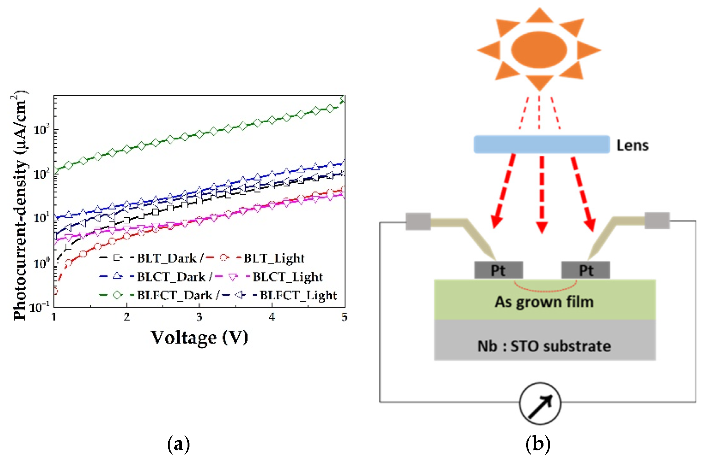
3.2. Photovoltaic (PV) Performance

The lattice parameters (0 0 16) of the grown film monotonically increased with temperature, without any discontinuity (Figure 6). Furthermore, no substantial changes were observed in the diffraction peaks, which may have indicated a transition from the tetragonal P4mm ferroelectric structure, at <400 °C; however, significant changes were observed at 450 and 500 °C for the BLCT and BLFCT films, respectively. Moreover, no changes were observed in the BLT film until 600 °C. Although the phase change temperature was lower than that of the BLT film, we confirmed that all samples maintained their structure at temperatures above 450 °C. The actual operating temperature for most applications, e.g., PVs and optoelectric, does not exceed 450 °C in practical use. The high crystalline quality of the thin films and substrates suggests that structural defects either on the substrate surface or in the thin film are unlikely to alter the phase transition behavior of BLT, BLCT, and BLFCT thin films.
Similar to other types of PV devices, ferroelectric-material-based PV devices should be able to absorb as much sunlight as possible to generate considerable photocurrent, for which they require ferroelectric materials with large absorption coefficients and low bandgaps. The most commonly used ferroelectric materials, e.g., LiNbO3, BaTiO3, and PZT crystals, exhibit bandgaps greater than 3 eV and can harvest sunlight in the UV range [27,28]. However, light with wavelengths less than 400 nm accounts for approximately 3.5% of the overall solar energy. As shown in Figure 4b and Figure 6, the doped BLT films have maintained the polarization loops and phase transition behavior of ferroelectric materials. Figure 5b–e show that the optical bandgap decreases from 2.64 to 2.08 eV owing to different doping concentrations.
To estimate the contribution of reducing the bandgap of the BLCT and BLFCT films, their photocurrent densities (J) were measured. As shown in Figure 7, all films exhibit almost zero current in the absence of light (dark current), while their photocurrent response is significantly enhanced in the presence of light. The lens was used to enhance the light using concentrator PVs. The photocurrent densities of the BLCT (157.32 uA/cm2) and BLFCT films (2974.3 uA/cm2) were 1.7 times and 32.2 times higher than that of the BLT film (92.38 uA/cm2) under the light of concentrator PVs (lens microscope with 10× magnification) (Figure 7a,b)). Platinum was deposited as the electrode on the surface to optimize electrical conductivity [29,30,31]. Based on previous reports on BiFeO3 conductivity and PV reactions [32,33], the detected local conductivity changes on domain walls, consistent with different electronic properties, and the additional degree of control on the conductivity of the walls through the chemical doping of oxygen vacancies were obtained. The doping of the domain walls with Co and Fe atoms, which generate high conductivity, may be responsible for the high current obtained in the BLFCT PV reaction. As shown in Figure 7b, the photocurrent between the Pt electrodes on the film was measured at 0−4.8 V under the optical field. The results of photocurrent density confirm that the reduced bandgap based on dopants enhanced the photocurrent density of the BLT film, and the optical response of the doped BLT films was enhanced to efficiently absorb more photons.

4. Conclusions

In this study, the BLT materials were doped with Fe and Co to minimize the bandgap of the ferroelectric material and enhance the carrier lifetime, allowing additional free charge to be created by sunlight and removed from the device. The bandgap reduction is promoted by doping with Fe and Co, and its significant photocurrent density change is 32.2 times higher than that of BLT. Studies on ferroelectric PV devices have been increasing with the contribution of enhanced material engineering and new methods to use ferroelectric dipoles. These findings show that ferroelectrics can be applied to solar systems [34,35]. The reduction in the bandgap to 11.4% and 18.1% lower than the experimentally measured optical bandgap of the BLT film using a simple Fe- and Co-doping method was observed, while maintaining ferroelectricity by analyzing the doped films based on polarization loops and the temperature range of the out-of-plane lattice parameters.
Although very simple doping was used here, the properties of ferroelectric thin films after doping are very objective, and this simple technique using doping would be used to tune additional wide-bandgap materials to enable. It can be used for solar energy conversion or optoelectronic applications to facilitate the further development of ferroelectric solar cells.

Author Contributions

Sample fabrication and original draft preparation, R.T. and R.H.; experimental supporting and editing, S.K.; supervision and editing, C.W.B. All authors have read and agreed to the published version of the manuscript.

Funding

This work was supported by grants from Gachon University (Grant No. GCU-202103850001).

Institutional Review Board Statement

Not applicable.

Informed Consent Statement

Not applicable.

Data Availability Statement

Not applicable.

Acknowledgments

We thank the Smart Materials Research Center for IoT supported by NFEC at Gachon University for its instrumental support (XRD, SEM).

Conflicts of Interest

The authors declare no conflict of interest.

List of Acronyms and Symbols

Co-first authors
*Corresponding authors
BLTBi3.25La0.75Ti3O12
BLCTBi3.25La0.75Co1Ti2O12
BLFCTBi3.25La0.75Fe0.25Co0.75Ti2O12
FE-PVFerroelectric photovoltaic
RFRadio frequency
XRDX-ray diffraction
FE-SEMField Emission Scanning Electron Microscope
AFMAtomic force microscopy
Nd-STONb-doped SrTiO3

References

  1. Tsoutsos, T.; Frantzeskaki, N.; Gekas, V. Environmental impacts from the solar energy technologies. Energy Policy 2005, 33, 289–296. [Google Scholar] [CrossRef]
  2. Würfel, P.; Würfel, U. Physics of Solar Cells: From Basic Principles to Advanced Concepts, 2nd ed.; John Wiley & Sons: Hoboken, NJ, USA, 2016; pp. 1–9. [Google Scholar]
  3. Yuan, Y.; Xiao, Z.; Yang, B.; Huang, J. Arising applications of ferroelectric materials in photovoltaic devices. J. Mater. Chem 2014, 2, 6027–6041. [Google Scholar] [CrossRef]
  4. Nakamura, S.M.; Horiuchi, F.K.; Ogawa, T.K.N.; Tokura, M.K.Y. Shift current photovoltaic effect in a ferroelectric charge-transfer complex. Nat. Commun 2017, 8, 1–6. [Google Scholar] [CrossRef] [PubMed]
  5. Butler, K.T.; Frost, J.M.; Walsh, A. Ferroelectric materials for solar energy conversion: Photoferroics revisited. Energy Environ. Sci. 2014, 8, 838–848. [Google Scholar] [CrossRef]
  6. Gao, J.; Xue, D.; Liu, W.; Zhou, C.; Ren, X. Recent Progress on BaTiO3-Based Piezoelectric Ceramics for Actuator Applications. Actuators 2017, 6, 24. [Google Scholar] [CrossRef]
  7. Mistewicz, K.; Nowak, M.; Stróż, D. A Ferroelectric-Photovoltaic Effect in SbSI Nanowires. Nanomaterials 2019, 9, 580. [Google Scholar] [CrossRef]
  8. Kobayashi, M.; Makino, H.; Nakatsuma, K. Effects of Powder Phase Properties on Pb(Zr, Ti)O3/Pb(Zr, Ti)O3 Sol-Gel Composites. Preprints 2019, 2019, 2019090193. [Google Scholar]
  9. Walker, J.; Ursic, H.; Bencan, A.; Malic, B.; Simons, H.; Reaney, I.; Viola, G.; Nagarajan, V.; Rojac, T. Temperature dependent piezoelectric response and strain–electric-field hysteresis of rare-earth modified bismuth ferrite ceramics. J. Mater. Chem. 2016, 4, 7859–7868. [Google Scholar] [CrossRef]
  10. Afify, H.A.; Sytnyk, M.; Zhou, S.; Osvet, A.; Brabec, C.J.; Korczak, J.; Szczerbakow, A.; Story, T.; Heiss, W. Perspectives of solution epitaxially grown defect tolerant lead-halide-perovskites and lead-chalcogenides. Appl. Phys. Lett. 2021, 119, 230501. [Google Scholar] [CrossRef]
  11. Bai, Y.; Yang, B.; Zhao, S. In-situ stress modulated ferroelectric photovoltaic effect in cluster-assembled TbFe2/Bi5Ti3FeO15 heterostructural films. Appl. Phys. Lett. 2019, 115, 261602. [Google Scholar] [CrossRef]
  12. Sun, Y.; Guo, F.; Chen, J.; Zhao, S. Improved ferroelectric and photovoltaic properties of BiMnO3 modified lead-free K0.5Na0.5NbO3 solid-solution films. Appl. Phys. Lett. 2017, 111, 253901. [Google Scholar] [CrossRef]
  13. An, H.; Han, J.Y.; Kim, B.; Song, J.; Jeong, S.Y.; Franchini, C.; Bark, C.W.; Lee, S. Large enhancement of the photovoltaic effect in ferroelectric complex oxides through bandgap reduction. Sci. Rep. 2016, 6, 28313. [Google Scholar] [CrossRef] [PubMed]
  14. Han, J.Y.; Bark, C.W. Influence of transition metal doping (X = Co, Fe) on structural, optical properties of Ferroelectric Bi3.25La0.75X1Ti2O12. Nano Converg. 2015, 2, 1–5. [Google Scholar] [CrossRef]
  15. Tang, R.; Kim, S.; Bark, C.W. Change of Phase Transition Temperature in Band Engineered Ferroelectric Lanthanum-Modified Bismuth Titanates. J. Nanosci. Nanotechnol. 2020, 20, 7135–7139. [Google Scholar] [CrossRef]
  16. Ramesh, R.; Schlom, D.G. Creating emergent phenomena in oxide superlattices. Nat. Rev. Mater. 2019, 4, 257–268. [Google Scholar] [CrossRef]
  17. Schlom, D.G.; Chen, L.-Q.; Pan, X.; Schmehl, A.; Zurbuchen, M. A Thin Film Approach to Engineering Functionality into Oxides. J. Am. Ceram. Soc. 2008, 91, 2429–2454. [Google Scholar] [CrossRef]
  18. Dunce, M.; Taukulis, R.; Birks, E.; Aulika, I.; Fuith, A.; Antonova, M.; Sternberg, A. Thermal Expansion, Burns Temperature and Electromechanical Properties in Na1/2Bi1/2TiO3-SrTiO3-PbTiO3 Solid Solutions. Ferroelectrics 2011, 424, 15–20. [Google Scholar] [CrossRef]
  19. Lee, H.N.; Hesse, D. Anisotropic ferroelectric properties of epitaxially twinned Bi3.25La0.75Ti3O12 thin films grown with three different orientations. Appl. Phys. Lett 2002, 80, 1040–1042. [Google Scholar] [CrossRef]
  20. Deus, R.; Gonçalves, L.; Cavalcanti, C.; Rocha, L.; Longo, E.; Simões, A. Magnetocoupling and domain structure of BiFeO3/LaFeO3 heterostructures deposited on LaSrCoO3/Pt/TiO2/SiO2/Si (100) substrates by the soft chemical method. J. Mater. Sci. Mater. Electron. 2017, 28, 8630–8642. [Google Scholar] [CrossRef]
  21. Wood, D.; Tauc, J. Weak absorption tails in amorphous semiconductors. Phys. Rev. 1972, 5, 3144. [Google Scholar] [CrossRef]
  22. Viezbicke, B.D.; Patel, S.; Davis, B.E.; Birnie III, D.P. Evaluation of the Tauc method for optical absorption edge determination: ZnO thin films as a model system. Phys. Status Solidi (B) 2015, 252, 1700–1710. [Google Scholar] [CrossRef]
  23. Wu, F.X.; Chen, Z.; Chen, Y.; Zhang, S.-T.; Zhou, J.; Zhu, Y.-Y.; Chen, Y.-F. Significant ferrimagnetism observed in Aurivillius Bi4Ti3O12 doped by antiferromagnetic LaFeO3. Appl. Phys. Lett. 2011, 98, 212501. [Google Scholar] [CrossRef]
  24. Krzhizhanovskaya, M.; Filatov, S.; Gusarov, V.; Paufler, P.; Bubnova, R.; Morozov, M.; Meyer, D. Aurivillius phases in the Bi4Ti3O12/BiFeO3 system: Thermal behaviour and crystal structure. Z. Anorg. Allg. Chem. 2005, 631, 1603–1608. [Google Scholar] [CrossRef]
  25. Seok Choi, W.; Nyung Lee, H. Band gap tuning in ferroelectric Bi4Ti3O12 by alloying with LaTMO3 (TM = Ti, V, Cr, Mn, Co, Ni, and Al). Appl. Phys. Lett 2012, 100, 132903. [Google Scholar] [CrossRef]
  26. Jia, C.; Chen, Y.; Zhang, W. Optical properties of aluminum-, gallium-, and indium-doped Bi4Ti3O12 thin films. J. Appl. Phys. 2009, 105, 113108. [Google Scholar] [CrossRef]
  27. Pal, P.; Rudrapal, K.; Maji, P.; Chaudhuri, A.R.; Choudhury, D. Toward an Enhanced Room-Temperature Photovoltaic Effect in Ferroelectric Bismuth and Iron Codoped BaTiO3. J. Phys. Chem. C 2021, 125, 5315–5326. [Google Scholar] [CrossRef]
  28. Tan, Z.; Hong, L.; Fan, Z.; Tian, J.; Zhang, L.; Jiang, Y.; Hou, Z.; Chen, D.; Qin, M.; Zeng, M. Thinning ferroelectric films for high-efficiency photovoltaics based on the Schottky barrier effect. NPG Asia Mater 2019, 11, 1–13. [Google Scholar] [CrossRef]
  29. Aggas, J.R. Electrical Characterization of Gold and Platinum Thin Film Electrodes with Polyaniline Modified Surfaces; Clemson University: Clemson, SC, USA, 2015; p. 2259. [Google Scholar]
  30. Kim, H.J.K.; Kaplan, K.E.; Schindler, P.; Xu, S.; Winterkorn, M.M.; Heinz, D.B. Electrical Properties of Ultrathin Platinum Films by Plasma-Enhanced Atomic Layer Deposition. ACS Appl. Mater. Interfaces 2019, 11, 9594–9599. [Google Scholar] [CrossRef]
  31. Ehsan, M.A.; Suliman, M.H.; Rehman, A.; Hakeem, A.S.; Al Ghanim, A.; Qamar, M. Fabrication of platinum thin films for ultra-high electrocatalytic hydrogen evolution reaction. Int. J. Hydrog. Energy 2020, 45, 15076–15085. [Google Scholar] [CrossRef]
  32. Bhatnagar, A.; Chaudhuri, A.R.; Kim, Y.H.; Hesse, D.; Alexe, M. Role of domain walls in the abnormal photovoltaic effect in BiFeO3. Nat. Commun. 2013, 4, 1–8. [Google Scholar] [CrossRef]
  33. Seidel, J.; Maksymovych, P.; Batra, Y.; Katan, A.; Yang, S.-Y.; He, Q.; Baddorf, A.P.; Kalinin, S.V.; Yang, C.-H.; Yang, J.-C. Domain wall conductivity in La-doped BiFeO3. Phys. Rev. Lett. 2010, 105, 197603. [Google Scholar] [CrossRef] [PubMed] [Green Version]
  34. Zhang, Q.; Xu, F.; Xu, M.; Li, L.; Lu, Y.; Li, M.; Li, P.; Li, M.; Chang, G.; He, Y. Lead-free perovskite ferroelectric thin films with narrow direct band gap suitable for solar cell applications. Mater. Res. Bull. 2017, 95, 56–60. [Google Scholar] [CrossRef]
  35. An, H.; Hong, H.J.; Jo, Y.-R.; Jung, S.-G.; Kim, S.M.; Lee, J.; Choi, H.; Yoon, H.; Kim, S.-Y. Reversible magnetoelectric switching in multiferroic three-dimensional nanocup heterostructure films. NPG Asia Mater 2019, 11, 1–10. [Google Scholar] [CrossRef] [Green Version]
Figure 1. (a) the flowchart for the target fabrication procedure and (b) the schematic diagram of off-axis RF magnetron sputtering inter configuration.
Coatings 12 01315 g001
Figure 2. X-ray diffraction patterns of the BLT, BLCT, and BLFCT epitaxial films on the Nb-doped SrTiO3 (001) substrate.
Coatings 12 01315 g002
Figure 3. Surface morphologies (FE-SEM and AFM images) of the derived thin films; (a,d) BLT, (b,e) BLCT, and (c,f) BLFCT.
Coatings 12 01315 g003
Figure 4. (a) Polarization-electric field loops were observed using the ferroelectric tester for the BLT, BLCT, and BLFCT films on the Nb-SrTiO3 (001) substrate (Room temperature, frequency of 10 kHz). (b,c) P-E hysteresis loops for the two films; BLT and BLCT films were tested with the frequency range of 0.8–20 kHz.
Coatings 12 01315 g004
Figure 5. Optical response of BLT, BLCT, and BLFCT films grown on the Nb-SrTiO3 (001) substrate; (a) Absorbance data with the wavelength (385–800 nm), and (bd) bandgap energy estimated by extrapolating the linear part of the (αhν)2 versus energy plots for BLT, BLCT, and BLFCT on the Nb-STO substrate.
Coatings 12 01315 g005
Figure 6. Out-of-plane-lattice parameters versus temperature for BLT (0 0 16), BLCT (0 0 16), and BLFCT (0 0 16) grown on the Nb-STO substrate.
Coatings 12 01315 g006
Figure 7. (a) Photocurrent densities of the pristine BLT and doped films on the Nb-STO substrate. (b) Photocurrent measurement. Pt electrodes are deposited on the films, and the current-density is measured between the two electrodes.
Coatings 12 01315 g007
Publisher’s Note: MDPI stays neutral with regard to jurisdictional claims in published maps and institutional affiliations.

