
Characteristics of Thin High Entropy Alloy Films Grown by Pulsed Laser Deposition

 ,
,  , , and
Abstract
:1. Introduction
2. Experimental Details
3. Results and Discussion
4. Conclusions
Author Contributions
Funding
Institutional Review Board Statement
Informed Consent Statement
Data Availability Statement
Acknowledgments
Conflicts of Interest
References
- Zhang, J.; Cai, C.; Kim, G.; Wang, Y.; Chen, W. Composition design of high-entropy alloys with deep sets learning. NPJ Comput. Mater. 2022, 8, 89. [Google Scholar] [CrossRef]
- Nadzri, N.I.M.; Khemar, A.; Wahab, J.A.; Mahat, M.M. High Entropy Alloy Towards Functional Materials Application: A Review. J. Phys. Conf. Ser. 2022, 2169, 012007. [Google Scholar] [CrossRef]
- Satyanarayana, M.B.; Yeh, J.-W.; Ranganathan, S.; Bhattacharjee, P.P. High-Entropy Alloys; Elsevier: Amsterdam, The Netherlands, 2019. [Google Scholar]
- Fourth, E.; Ashby, M.F. Material Selection in Mechanical Design, 4th ed.; Butterworth-Heinemann Elsevier: Oxford, UK, 2011; ISBN 9780080952239. [Google Scholar]
- Sheikh, S. Alloy Design and Optimization of Mechanical Properties of High-Entropy Alloys. Ph.D. Thesis, Chalmers Tekniska Hogskola, Gothenburg, Sweden, 2016. [Google Scholar]
- Zhang, W.; Liaw, P.K.; Zhang, Y. Science and technology in high-entropy alloys. Sci. China Mater. 2018, 61, 2–22. [Google Scholar] [CrossRef]
- Peter, I.; Rosso, M. Light alloys from traditional to innovative technologies. New Trends in Alloy Development. Charact. Appl. 2015, 3, 37. [Google Scholar]
- Cantor, B.; Chang, I.T.H.; Knight, P.; Vincent, A.J.B. Microstructural development in equiatomic multi-component alloys. Mater. Sci. Eng. A 2004, 375, 213–218. [Google Scholar] [CrossRef]
- Zhang, Y.; Zuo, T.T.; Tang, Z.; Gao, M.C.; Dahmen, K.A.; Liaw, P.K.; Lu, Z.P. Micro-structures and properties of high-entropy alloys. Prog. Mater. Sci. 2014, 61, 1–93. [Google Scholar] [CrossRef]
- Chapelle, P.; Bellot, J.P.; Duval, H.; Jardy, A.; Ablitzer, D. Modelling of plasma generation and expansion in a vacuum arc: Application to the vacuum arc remelting process. J. Phys. D Appl. Phys. 2001, 35, 137–150. [Google Scholar] [CrossRef]
- Tokarewicz, M.; Grądzka-Dahlke, M. Review of Recent Research on AlCoCrFeNi High-Entropy Alloy. Metals 2021, 11, 1302. [Google Scholar] [CrossRef]
- Zhang, Y.; Xing, Q. High Entropy Alloys: Manufacturing Routes. In Reference Module in Materials Science and Materials Engineering; Elsevier: Amsterdam, The Netherlands, 2020. [Google Scholar]
- Agumba, O.J. Design and Fabrication of a Simple Four Point Probe System for Electrical Characterization of Thin Films. Ph.D. Thesis, Kenyatta University, Nairobi, Kenya, 2010. [Google Scholar]
- Hertz, H. Ueber einen Einfluss des ultravioletten Lichtes auf die electrische Entladung. Ann. Phys. 1887, 267, 983–1000. [Google Scholar] [CrossRef]
- Einstein, A. On a heuristic point of view concerning the production and transformation of light. Ann. Phys. 1905, 1–18. [Google Scholar] [CrossRef]
- Leyland, A.; Matthews, A. On the significance of the H/E ratio in wear control: A nanocomposite coating approach to optimised tribological behaviour. Wear 2000, 246, 1–11. [Google Scholar] [CrossRef]
- Tsui, T.Y.; Pharr, G.M.; Oliver, W.C.; Bhatia, C.S.; White, R.L.; Anders, S.; Anders, A.; Brown, I.G. Nanoindentation and Nanoscratching of Hard Carbon Coatings for Magnetic Disks. MRS Proc. 1995, 383, 447. [Google Scholar] [CrossRef]
- López Ríos, M.; Perdomo, P.P.S.; Voiculescu, I.; Geanta, V.; Crăciun, V.; Boerasu, I.; Rosca, J.C.M. Effects of nickel content on the microstructure, microhardness and corrosion behavior of high-entropy Al-CoCrFeNix alloys. Sci. Rep. 2020, 10, 21119. [Google Scholar] [CrossRef]
- Sim, R.K.; Xu, Z.; Wu, M.Y.; He, A.; Chen, D.L.; Li, D.Y. Microstructure, mechanical properties, corrosion and wear behavior of high-entropy alloy AlCoCrFeNix ($$ x> 0$$ x> 0 the) and medium-entropy alloy ($$ x= 0$$ x= 0). J. Mater. Sci. 2022, 57, 11949–11968. [Google Scholar] [CrossRef]
- Tian, Q.W.; Zhang, G.J.; Yin, K.X.; Cheng, W.L.; Wang, Y.N.; Huang, J.C. Effect of Ni content on the phase formation, tensile properties and deformation mechanisms of the Ni-rich AlCoCrFeNix (x = 2, 3, 4) high entropy alloys. Mater. Charact. 2021, 176, 111148. [Google Scholar] [CrossRef]
- Cao, L.; Wang, X.; Wang, Y.; Zhang, L.; Yang, Y.; Liu, F.; Cui, Y. Microstructural evolution, phase formation and mechanical properties of multi-component AlCoCrFeNix alloys. Appl. Phys. A 2019, 125, 699. [Google Scholar] [CrossRef]


| Bulk Source | Thin Film No. | Substrate | Deposition Parameters | ||||
|---|---|---|---|---|---|---|---|
| pu (mbar) | pN2 (mbar) | T (min) | E (mJ) | Tsubst (°C) | |||
| (a) HEA2 | 1 | Glass | 4.0 × 10⁻⁷ | 1.0 × 10⁻⁴ | 12 | 450 | RT |
| 2 | Glass | 4.2 × 10⁻⁷ | - | 12 | 450 | RT | |
| 3 | Si | 1.9 × 10⁻⁷ | - | 12 | 450 | RT | |
| 4 | Si | 1.6 × 10⁻⁷ | 1.0 × 10⁻⁴ | 12 | 450 | RT | |
| (b) HEA6 | 1 | Glass | 4.3 × 10⁻⁷ | 1.0 × 10⁻⁴ | 12 | 450 | RT |
| 2 | Si | 1.3 × 10⁻⁷ | - | 12 | 450 | RT | |
| 3 | Si | 4.5 × 10⁻⁷ | 1.0 × 10⁻⁴ | 12 | 450 | RT | |
| 4 | Glass | 1.7 × 10⁻⁷ | - | 12 | 450 | RT | |
| (c) HEA10 | 1 | Glass | 4.5 × 10⁻⁷ | - | 10 | 450 | RT |
| 2 | Si | 1.7 × 10⁻⁷ | - | 12 | 450 | RT | |
| 3 | Si | 3.3 × 10⁻⁷ | 1.0 × 10⁻⁴ | 12 | 450 | RT | |
| 4 | Glass | 2.2 × 10⁻⁷ | 1.0 × 10⁻⁴ | 9 | 450 | RT | |
| 5 | Glass | 2.0 × 10⁻⁷ | - | 15 | 200 | RT | |
| 6 | Glass | 6.0 × 10⁻⁷ | 1.0 × 10⁻³ | 12 | 385 | RT | |
| 7 | Glass | 2.0 × 10⁻⁷ | 1.0 × 10⁻⁴ | 14 | 371 | RT | |
| 8 | Glass | 3.0 × 10⁻⁷ | 1.0 × 10⁻⁵ | 12 | 375 | RT | |
| 9 | Glass | 1.9 × 10⁻⁷ | - | 12 | 400 | RT | |
| 10 | Glass | 2.3 × 10⁻⁷ | - | 12 | 300 | RT | |
| Bulk Source | Thin Film No. | Grain Size [Å] | Lattice Parameter [Å] |
|---|---|---|---|
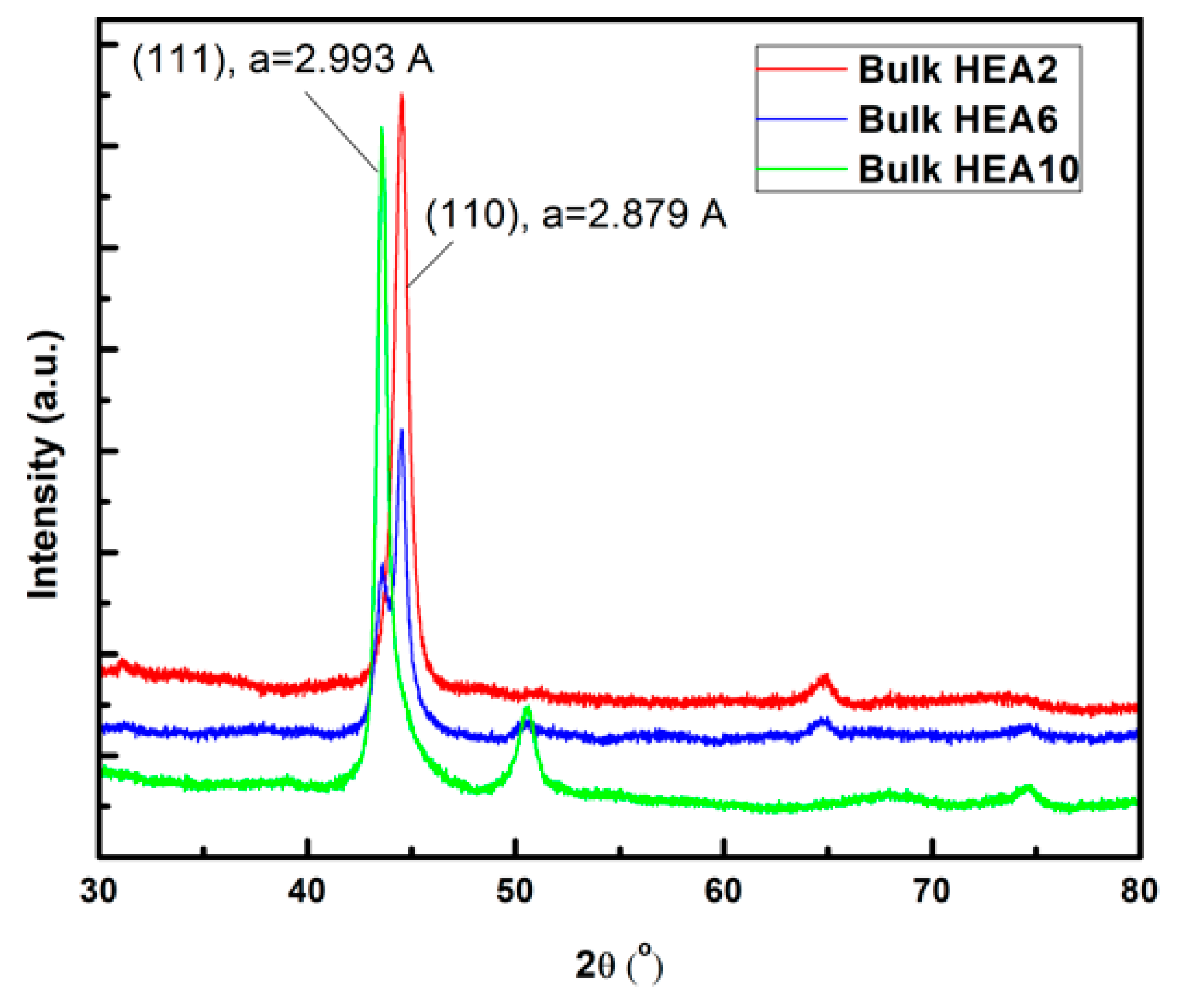
| HEA2 | (target) | 90 (bcc) | 2.879 (bcc) |
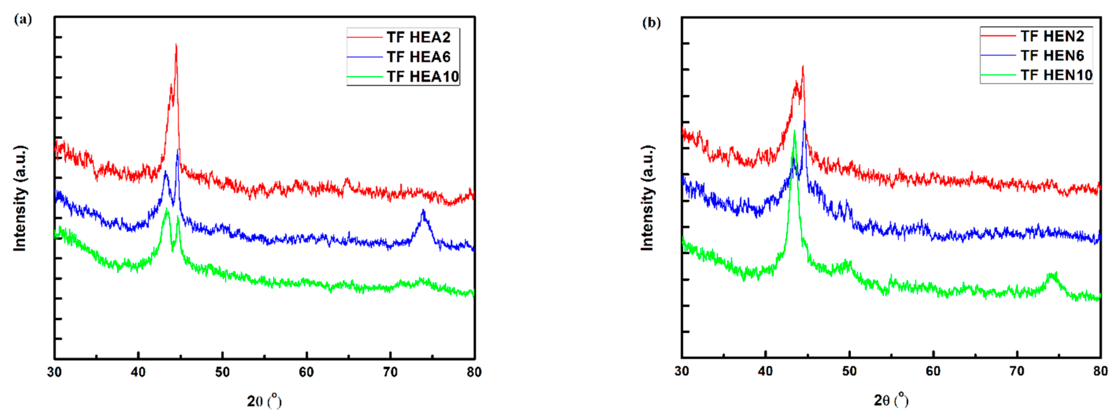
| 1 (N2) | 112 (bcc) 37 (fcc) | 2.884 (bcc) 3.008 (fcc) | |
| 2 (vacuum) | 208 (bcc) 66 (fcc) | 2.879 (bcc) 2.981 (fcc) | |
| HEA6 | (target) | 114 (bcc) 112 (fcc) | 2.879 (bcc) 2.995(fcc) |
| 1 (N2) | 145 (bcc) 38 (fcc) | 2.874 (bcc) 3.017 (fcc) | |
| 4 (vacuum) | 142 (bcc) 62 (fcc) | 2.872 (bcc) 3.015 (fcc) | |
| HEA10 | (target) | 117 (fcc) | 2.993 (fcc) |
| 4 (N2) | 52 (fcc) | 3.006 (fcc) | |
| 1 (vacuum) | 182 (bcc) 41 (fcc) | 2.865 (bcc) 3.015 (fcc) |
| Bulk Source | Thin Film No. | Thickness, t [m] | (U/I)min [mV/mA] | Rs [Ω] | Resistivity, ρ [µΩ-cm] |
|---|---|---|---|---|---|
| HEA2 | 2 (vacuum) | 1.77 × 10⁻⁷ | 1.31 | 5.93 | 105.3 |
| 4 (N2) | 2.32 × 10⁻⁷ | 1.43 | 6.48 | 150.6 | |
| HEA6 | 2 (vacuum) | 1.37 × 10⁻⁷ | 1.72 | 7.79 | 106.7 |
| 3 (N2) | 2.66 × 10⁻⁷ | 1.61 | 7.29 | 194.1 | |
| HEA10 | 2 (vacuum) | 1.19 × 10⁻⁷ | 1.67 | 7.56 | 90.4 |
| 4 (N2) | 1.64 × 10⁻⁷ | 1.71 | 7.75 | 127.2 |
Publisher’s Note: MDPI stays neutral with regard to jurisdictional claims in published maps and institutional affiliations. |
© 2022 by the authors. Licensee MDPI, Basel, Switzerland. This article is an open access article distributed under the terms and conditions of the Creative Commons Attribution (CC BY) license (https://creativecommons.org/licenses/by/4.0/).
Share and Cite
Laszlo, E.A.; Crăciun, D.; Dorcioman, G.; Crăciun, G.; Geantă, V.; Voiculescu, I.; Cristea, D.; Crăciun, V. Characteristics of Thin High Entropy Alloy Films Grown by Pulsed Laser Deposition. Coatings 2022, 12, 1211. https://doi.org/10.3390/coatings12081211
Laszlo EA, Crăciun D, Dorcioman G, Crăciun G, Geantă V, Voiculescu I, Cristea D, Crăciun V. Characteristics of Thin High Entropy Alloy Films Grown by Pulsed Laser Deposition. Coatings. 2022; 12(8):1211. https://doi.org/10.3390/coatings12081211
Chicago/Turabian StyleLaszlo, Edwin Alexandru, Doina Crăciun, Gabriela Dorcioman, Gabriel Crăciun, Victor Geantă, Ionelia Voiculescu, Daniel Cristea, and Valentin Crăciun. 2022. "Characteristics of Thin High Entropy Alloy Films Grown by Pulsed Laser Deposition" Coatings 12, no. 8: 1211. https://doi.org/10.3390/coatings12081211