
Nano- and Micro-Scale Impact Testing of Hard Coatings: A Review


Micro Materials Ltd., Willow House, Yale Business Village, Ellice Way, Wrexham LL13 7YL, UK
Coatings 2022, 12(6), 793; https://doi.org/10.3390/coatings12060793
Submission received: 6 May 2022
/
Revised: 5 June 2022
/
Accepted: 6 June 2022
/
Published: 8 June 2022
(This article belongs to the Special Issue 10th Anniversary of Coatings: Invited Papers in "Surface Characterization, Deposition and Modification" Section)
Abstract
:In this review, the operating principles of the nano-impact test technique are described, compared and contrasted to micro- and macro-scale impact tests. Impact fatigue mechanisms are discussed, and the impact behaviour of three different industrially relevant coating systems has been investigated in detail. The coating systems are (i) ultra-thin hard carbon films on silicon, (ii) DLC on hardened tool steel and (iii) nitrides on WC-Co. The influence of the mechanical properties of the substrate and the load-carrying capacity (H3/E2) of the coating, the use of the test to simulate erosion, studies modelling the nano- and micro-impact test and performing nano- and micro-impact tests at elevated temperature are also discussed.
1. Introduction
Impact resistance is critical in many applications of coating systems involving highly loaded mechanical contact. These include automotive and aero-engine components and interrupted high-performance machining operations where intermittent high strain rate contact occurs [1,2,3]. In a diesel engine system, diamond-like carbon (DLC) coatings are deposited on many components in the powertrain, including fuel injectors, tappets, pistons, and piston rings, where they can be subjected to repetitive impacts in service [2]. In a gas turbine engine, high-temperature erosion of the thermal barrier coatings that protect the underlying superalloy turbine blades is a key factor lowering service life and restricting operating temperatures.
Cyclic impact tests are used as model tests for assessing coating durability under dynamic loading [4,5,6]. Bulk materials and coatings systems often undergo fatigue deformation mechanisms in the multi-cycle tests that are not observed in single-cycle tests [7,8]. In an impact test on a coated system, the test severity and positions of peak impact-induced stresses relative to the coating–substrate interface can be controlled by varying the impact energy and the geometry of the test probe. Fatigue mechanisms can vary with the ratio of coating thickness t to the indenter radius R [9,10] (t/R), so it can be very useful to perform impact tests with different contact sizes to obtain data over a range of t/R. Therefore, macro-scale, micro-scale and nano-scale impact tests have been developed. The differences between them and how these influence the observed behaviour is discussed in more detail in later sections. Deformation and failure mechanisms depend on applied load and indenter sharpness. t/R values are very low (≈0.001) in macro-scale tests of thin physical vapour deposition (PVD) coatings with cemented carbide or hardened steel spherical indenters with 1–3 mm end radius. The peak von Mises stresses that result in plastic deformation are located deep into the substrate, and hence, the fatigue behaviour can be strongly influenced by the substrate properties [1,4,5,6,7,11]. Although they can be useful, macro-scale impact tests have some limitations. An alternative approach to determining coating fatigue resistance is to perform nano-scale impact tests at higher t/R with much sharper probes. These accelerated tests are of much shorter duration than macro-scale tests and subject coatings to more severe conditions that replicate the high stresses generated in actual operating conditions. The position of peak von Mises stresses relative to the coating-substrate interface is completely different in the nano- and macro-scale tests. Nano-impact tests are very sensitive to small differences in coating properties and have shown excellent correlation to coating performance in applications. In particular, there have been many studies on Al-rich (Ti,Al)N-based PVD coatings on cemented carbide that have shown strong correlation between the wear of coated tools in high-speed machining applications and the fracture resistance found in the nano-impact test [12,13,14,15,16,17,18,19,20,21,22,23].
Nano-impact testing utilises the depth-sensing capability of a multifunctional nanomechanical test system (NanoTest system, Micro Materials Ltd., Wrexham, UK) to perform impact testing at strain rates that are several orders of magnitude higher than those in quasi-static indentation tests [24,25,26,27,28,29]. Although nano-impact is the most common terminology, the technique was originally termed micro-impact [30] and has also been described as impact indentation or impulse impact. The small scale tests provide more localised assessment of impact resistance. They have potential advantages in high throughput, automation and surface sensitivity, so they are particularly suited to thin coatings/small volumes and in investigating the influence of nano/microstructure on performance.
To bridge the gap in t/R between the nano- and macro-ranges, the micro-impact test, involving higher loads and larger probe sizes than in nano-impact, has been developed as an instrumented accelerated test sensitive to coating and substrate together where stresses can be concentrated near interface(s) in the system [31,32,33,34,35,36,37]. In the micro-impact test, coating and substrate deformation is important, and coatings can be subjected to high bending stresses. The importance of the strain rate on the fatigue failure of coatings has been highlighted by Bouzakis and co-workers, with even only a relatively modest increase in strain rate decreasing the fatigue endurance limit of Al0.6Ti0.4N-coated WC-Co [38]. The high strain rate contact in nano- and micro-impact tests can provide closer simulation of the performance of coatings systems under highly loaded intermittent contact and the evolution of wear under these conditions than tests at a lower strain rate.
Originally envisaged as a test method primarily to assess the degradation of coatings to repeated localised stresses, the availability of single and multiple impact configurations, nano- and micro-scale load ranges and different indenter geometries have resulted in the development of a wide range of applications [39,40,41,42,43,44,45,46,47,48,49,50,51,52,53,54,55,56,57,58,59]. Applications of single impact tests have included (i) strain rate sensitivity [24,25,27,28], (ii) dynamic hardness [29,41,42], (iii) dynamic H/E [45], (iv) energy absorption [40] and (v) particle–matrix delamination [46]. Applications of repetitive impact tests have included (i) the evolution of dynamic hardness and debonding [51], (ii) erosive wear simulation by matching contact size [43], (iii) fracture toughness [56], and (iv) understanding how hierarchical structures influence damage tolerance in natural tough materials [47]. A single impact is effectively a high strain rate indentation test. Analysis methods for single-impact data have been developed using the approaches outlined by Schuh, van Vliet and others [24,29,41] to measure the dynamic hardness (impulse hardness) of the material, i.e., its effective hardness at high strain rate. The nano-impact test has also been used to assess toughness at a small scale [56]. Although it does not measure quasi-static fracture toughness K1c, it can provide a quantitative assessment of resistance to fatigue fracture, or effective dynamic toughness, under repetitive loading. The power of the test as a reliable simulation tool is that in many cases, this is more representative of actual contact conditions in applications; i.e., wear resistance is controlled by a combination of load support and resistance to fracture rather than by coating hardness or toughness alone. To improve our understanding of coating system behaviour under repetitive impact, it has proved beneficial to also (i) develop analysis methods for quantifying deformation in single impacts [40,41], (ii) perform repetitive impacts on uncoated substrates [49], (iii) develop test metrics from single impacts, which can be used to detect the onset of fracture [50,52], and (iv) support conclusions with multi-sensing approaches such as acoustic emission monitoring [53,54].
In this review, the operating principles of the nano-impact test technique are described, and nano-impact tests are compared to micro- and macro-scale tests. Impact fatigue mechanisms are discussed, and the impact behaviour of three different industrially relevant coating systems—(i) ultra-thin hard carbon films on silicon, (ii) diamond-like carbon (DLC) on hardened tool steel, and (iii) PVD nitrides on cemented carbide—is investigated in detail. This is followed by sections describing the influence of the substrate mechanical properties and the load-carrying capacity (H3/E2) of the coating, the use of the test to simulate erosion, studies modelling the nano- and micro-impact test and lastly, performing nano- and micro-impact tests at elevated temperature.
2. Nano-Impact—Experimental Setup, Test Basics and Test Metrics
In the nano-impact test, a diamond indenter is withdrawn to a set distance from the sample surface and then rapidly accelerated to produce a high strain rate impact event. The depth-sensing capability of a commercial nanoindentation system (NanoTest, Micro Materials Ltd., Wrexham, UK) is used to monitor the degradation of surface from repeated localised stresses at high rates of strain, which are orders of magnitude higher than in normal (quasi-static) nanoindentation. The configuration is shown schematically in Figure 1a.
An initial surface contact by the impact probe under a minimum contact load determines the depth zero at the beginning of the nano-impact test experiment. The actuated (static) coil force is then applied, producing elastoplastic deformation by indentation. The corresponding initial indentation depth under load, h0, which includes elastic and plastic deformation, is used to confirm that the depth zero is measured correctly and the test did not impact in an anomalous region of the surface. Repetitive contacts are produced by electromagnetic actuation where the impact probe is rapidly withdrawn from the surface (e.g., to 10 μm above the surface, as shown schematically on the left-hand side of Figure 1b) and then accelerated over this distance to impact the surface (right-hand side of Figure 1b), producing true high strain rate impact events (see also Figure 2) where the probe leaves the surface between each subsequent impact. The under-load impact depth, h, is always larger than h0, as the dynamic impact force is significantly larger than the static impact load, due to inertia. Once the probe comes to rest, it is retracted, and with periodic actuation, the surface re-impacted at the same position at a set frequency, typically at 4 s intervals, to produce a cyclic impact test. The position of the impacting diamond probe under load is recorded throughout the test, allowing the progression of damage to be monitored cycle by cycle. An example is shown in Figure 1b.
Several authors have shown that the strain rate at contact in the nano-impact test can be extremely high, typically in the region of 104–105 s−1 [26,27,28,55,57]. To illustrate this, Figure 2 shows how the strain rate varies with time during a single impact event on a bulk alumina sample when impacted by a cube corner diamond probe (three repeats are shown). Although the strain rate reduces after contact, it remains at a high level throughout the majority of the impact event.
Experimental parameters such as the test probe geometry, applied load, acceleration distance and the total number of impact cycles and their frequency are user-controlled in the nano-impact test to alter the severity of the test and its duration. A cube corner diamond indenter (with a small end radius of ≈50 nm) has been the most popular choice of impact probe, as its geometry produces high contact strain, which is beneficial in driving impact-induced fracture within a short test time. The applied load and accelerating distance control the impact energy delivered to the sample. Typical nano-impact test parameters that have been used for testing hard coatings are: (i) cube corner diamond impact probe, (ii) 90° impact angle, (iii) 25–150 mN applied load, (iv) 15 μm accelerating distance, (v) 0.25 Hz impact frequency, (vi) 300 s test duration (i.e., 75 impacts in total), (vii) 5–10 repeat tests at each load, and (viii) normal laboratory temperature (e.g., 22 °C). The general procedure for micro-impact tests is the same.
Qin and co-workers [29] have split the impact process into three stages: (i) acceleration, (ii) indentation, and (iii) rebound. High-resolution analysis of probe depth vs. time data is used to determine a range of metrics from single impacts including (i) coefficient of restitution (Vin/Vout) and (ii) from knowledge of the effective mass of the pendulum, fractional potential energy (KEin/KEout) [50]. Analysis of single nano-impacts [29] provided an estimate of the fraction of the impact energy transferred to the sample as ≈0.7 and the fraction lost through losses to the system, i.e., transmission into the pendulum, vibration, and air damping as ≈0.3.
The response of a material to repetitive contact in the nano-impact test depends on its ductility or brittleness. On a ductile material, there is a gradual increase in probe penetration depth. The rate of depth increase slows with continued impacts, particularly for strongly work-hardening materials. In contrast, for a brittle material, there are often several abrupt increases in probe depth during the test due to cohesive and/or interfacial failures. A typical example on a coating system is shown in Figure 3. At 50 mN, there was no clear failure, but at higher loads, the abrupt increases due to fracture are clear.
Since it is trivial to set up multiple tests in an automated schedule, typically, multiple replicate tests are performed at different positions (e.g., in a grid array) on the sample surface to improve the statistical significance of the results. The impact resistance of different coatings can be assessed by the number of impacts required for failure to occur in 50% of the tests. Rebound impacts are essentially elastic [39] so that only the initial impact in each cycle is counted. Failure probability can be estimated by ranking the number of impacts-to-failure events in order of increasing fatigue resistance and then assigning a probability of failure to the nth ranked failure event in a total sample size of N, according to Equation (1), in an analogous approach to the treatment of distributions of failure stresses in Weibull statistics.
P(f) = n/(N + 1)
By combining failure probability data at different loads, a plot of the number of impacts required for failure to occur in 50% of tests vs. the impact force can be obtained. Failure in the nano-impact test can be strongly load-dependent. As an example, Figure 4 illustrates how the failure probability changes with load and number of impacts for an 80 nm ta-C coating on Si when impacted by a spherical indenter with a 4.6 μm end radius [58].
Several methods have been used to confirm that the abrupt changes in depth (as shown in Figure 3) are due to the onset of fracture. Jennett and Nunn [50] have used high-resolution analysis to monitor the change in fractional potential energy absorbed with continued impacting, showing a marked increase in energy absorbed for the impacts that resulted in abrupt increases in probe depth. In nano-impact tests on the bulk ceramic materials, alumina and partially stabilised zirconia, simultaneous acoustic emission (AE) detection has been used to reveal which impacts cause cracking [53,54]. Although there was a correlation between impacts that caused a large increase in depth being accompanied by bursts of AE, the in situ monitoring of AE revealed a more complex behaviour with crack systems developing over several impacts before a larger burst of AE for the impact resulting in material removal under the impact probe. Shi and co-workers [52] used high-resolution data acquisition of single nano-impacts on CrN to reveal changes in depth–time data when fracture occurred. In cyclic impact, more stochastic behaviour is observed from the onset of cracking. An indirect but practically useful indication of fracture is the onset of variability in depth vs. number of impacts in repeat tests [58]. When there was no fracture in any of the tests, the reproducibility in probe depth was typically very good. Higher variability begins once fracture occurs after a certain number of impacts in some tests but not others.
3. Comparison between Nano-, Micro- and Macro-Scale Impact Tests
The general procedure for nano- and micro-impact tests is the same. In micro-impact tests on hard coatings, the experimental parameters are typically the same except for accelerating distance, applied load and probe geometry. The accelerating distance is typically set at 40 µm so that differences in impact energy are obtained by altering the applied load (0.5–5 N). Sphero-conical diamond test probes with end radii of 8–100 μm have been most commonly used [36,49,59]. The impact energy is given by the product of the impulse force and accelerating distance. Since the accelerating distance is typically kept constant, it is common to report data in terms of the actuated impact force. Due to higher forces and accelerating distances, the energy supplied in micro-impact is typically from ×100 to ×1000 greater than in the nano-impact test, which enables spherical probes to be used effectively, causing fracture rapidly.
Typical experimental parameters in each type of test are summarised in Table 1. Although the principles behind nano-/micro- and macro-scale impact tests are common, there is a fundamental difference of approach in the nano-/micro- tests, which are depth-sensing, as the change in depth under load is monitored throughout the test with a capacitive sensor, and the macro-impact tests, which are not depth-sensing. Instead, coating durability in macro-scale impact tests has been assessed by post-test evaluations of damage such as crater volume [60] or failed-area ratio (defined as area of substrate exposure divided by the total contact area) [4,61]. Nano- and micro-impact tests are accelerated tests that are typically much shorter and probe coating system behaviour under more severe conditions where there is greater coating strain. Detailed information on the fatigue failure mechanisms in nano/micro-impact tests is obtained through setting up automated arrays of rapid repeat tests at different loads (e.g., 5–10 repeats per load) with cycle-by-cycle monitoring of the damage providing a precise measure of the number of impact cycles to coating failure in each test.
The micro-impact test at higher t/R than macro-impact can be more sensitive to coating and substrate together, since stresses can be concentrated near interfaces in the coating system [31]. Beake, Liskiewicz and co-workers [31,32,33,34,35,36,37] have used this technique to investigate (i) impact resistance of hard carbon coatings on hardened tool steel [33,34,35,37] and (ii) PVD nitrides on WC-Co [31,32,36,37]. The impact energy in nano- and micro-impact tests is much lower than in the macro-scale tests, but critically, it is acting over a very small volume so that the resultant impact energy density is high. The size of the affected volume can be estimated by 2.4a × πa2, where a is the contact radius and 2.4a is the depth of the primary indentation zone [73,74]. In a study of micro-impact of TiAlCrN/NbN coatings, the calculated energy densities when using R = 8 or 20 μm probes were ≈2–4 GJ/m3, resulting in rapid fracture [36].
The potential advantages of studying coating fatigue resistance by nano- or micro-scale tests are the much shorter duration of the experiments compared to conventional, high-cycle macro-scale tests and impact-by-impact monitoring of the impact-induced deformation process that provides a precise record of the exact number of cycles to failure with detailed information on the fatigue failure mechanism. It is possible to use nano- or micro-impact testing to automatically build up complete S-N fatigue curves from single samples, enabling rapid screening to evaluate the performance of novel coating compositions and load-dependent deformation mechanisms to be evaluated.
4. Impact Fatigue Mechanisms
By altering the impact load, probe sharpness and test duration, it is possible to study fatigue mechanisms. In nano- and micro- scale impact tests, the instantaneous probe position is recorded throughout, so changing depth can be correlated with a post-test analysis of impact craters by SEM, with additional sub-surface information available from FIB cross-sections through the craters [75]. The initial resistance to crack nucleation and subsequent crack propagation under cyclic loading are studied by monitoring the evolution in probe depth.
When comparing coatings and their deformation mechanisms across wide force ranges and/or different probe geometries, it is common to plot depth vs. number of impacts from multiple tests together. However, small inflexions in probe depth that can occur at the onset of failure events may be obscured. As an alternate approach to compare coating behaviour at different applied load and/or with different probe geometries, the change in depth after the initial impact (i.e., [h − h0]) with continued impact can provide a more useful indication of the damage progression [37,49,59]. This approach enables (i) effective comparison of nano- and micro-impact data with different probe geometries and (ii) convenient investigation of load-dependent behaviour at either length scale whilst retaining the same probe geometry. However, it removes the effects of initial load-dependent coating bending. An example of this is discussed in more detail in Section 6 (Figure 10).
Coating failure in a nano-impact test is usually accompanied by abrupt increases in probe depth, as shown in Figure 3. For some coating systems, the on-load probe depth has been found to decrease with continued impacts under certain conditions when spherical probes are used [51,55,76]. This backward depth evolution has been confirmed [55] by post-test AFM imaging of impact scars showing volume uplift. This uplift has been considered to be the results of interfacial delamination occurring without (or before) the accompanying fracture that results in the increase in depth. It is more commonly found at low load where stresses are relatively low and impact-induced plasticity is minimised. This behaviour indicates that under certain conditions, the impact test may be used to assess adhesion strength, particularly where debonding is induced without being preceded by appreciable plasticity.
Experimental studies with a range of different probe geometries have clearly shown that hard PVD coatings can display fatigue behaviour under cyclic loading. The location and extent of cracking observed depends on a range of factors including coating and substrate mechanical properties and coating thickness, and test conditions including the test probe geometry, applied load and number of cycles. Experimental studies of repetitive micro-impact by spherical indenters with end radii 17–20 μm and macro-scale tests with larger radius probes have reported crack formation at the top surface at the periphery of the contact where high tensile stresses exist. For example, Tarrés and co-workers [77] have studied the damage mechanism under cyclic loading of PVD TiN-coated hard metal substrate by a 1.25 mm radius WC-Ni spherical indenter at 200–900 N. This occurred through (i) nucleation of a surface circular crack after plastic deformation of the substrate, (ii) gradual crack growth down from the coating surface with increasing cycles through the coating thickness, and (iii) substrate cracking without any intermediate interface delamination. The critical loads for cracking under monotonic and cyclic loading were used to determine the fatigue sensitivity of the TiN coating. Spherical probe geometry has been generally preferred for investigating repetitive indentation/impact damage evolution and fatigue sensitivity [77], but sharper probe geometries such as Vickers, Berkovich or cube corner also can generate surface fatigue. For example, surface radial cracks which grow gradually extend from the impact zone with an increasing number of cycles and/or load. In cyclic Vickers indentation of hard coatings on tool steels, the observed crack morphology around the indent was found to depend on the H/E ratio of the coatings [78]. A quasi-plastic damage mode with radial cracks that increased in length under continued cyclic loading was found in coatings with relatively lower H/E [78].
Thin zirconia, alumina and zirconia-alumina bi-layer coatings deposited on glass have been studied by nano- and micro-impact testing [59] as a model brittle coating/brittle substrate system. Back-scattered SEM imaging revealed a range of load-dependent deformation mechanisms including (i) radial cracking without chipping/delamination, (ii) concentric ring cracks leading to chipping/delamination, (iii) chipping/delamination accompanied by spiral cracking outside the chipped/delaminated region and (iv) chipping/delamination accompanied by substrate fracture. A range of load-dependent mechanisms were also found in micro-impact testing of TiAlCrN/NbN nanomultilayered coatings on WC-Co [36]. Ring cracks precede radial cracks in indentation [79]. In spherical indentation and cyclic fatigue tests, circumferential cracking is commonly observed initially, transitioning to radial cracking and chipping at higher loads and/or longer cycling.
FIB milling has been used to study sub-surface crack networks developed by repetitive nano-impact testing. Zhang and co-workers [57] observed that lateral cracks developed in 10 μm TiN/Ti multilayers on Ti6Al4V. Chen and co-workers noted [75] that despite extensive spallation, there was no interfacial cracking in TiAlSiN and TiN coatings on hardened steel. Ma and co-workers used [80] X-FIB to show that degradation in columnar TiN and TiAlN-TiN bilayer coatings on steel subjected to indentation with a spherical indenter was predominantly by shear at columnar grain boundaries. Circumferential cracking outside the indentation zone was also observed. In cyclic loading of ≈1.5 μm thick TiN on 304 stainless steel with a R = 5 μm indenter; Cairney and co-workers [81] used FIB to show that the principal deformation mechanism appeared to be sliding along intercolumnar cracks. They proposed that fatigue occurred through a reduction in the shear stress at the column boundaries with repeated indentation. The reduction in shear stress resulted in greater load being transferred to the softer substrate, with a consequent increase in penetration depth [81]. Shi and co-workers [82] noted that in nano- and micro-impact tests on graphitic carbon coatings on stainless steel substrate, i.e., a substrate that does not provide as much load support as hardened tool steel, the failure location was not at the periphery of the crater but in the centre (underneath).
Abdollah and co-workers [83] proposed a three-stage impact deformation–wear transition map to describe wear evolution in impact tests of a DLC coating at 70–240 N with a 1 mm radius steel indenter: (i) initial steel substrate plastic deformation occurring without coating wear, (ii) suppression of substrate plasticity and (iii) coating wear. Boundaries between these regions depended [83] on the impact load and number of impact cycles. Under these conditions (low t/R), the presence of the thin hard coating barely influences the elastoplastic deformation of the steel substrate, and the mean contact pressure was close to 1.1 times the substrate yield stress. In micro-impact tests of graded a-C:H and a-C coatings on hardened M2 steel, the mean pressure during the test was calculated from the dynamic impact force and the contact area under load [33]. The contact pressure gradually reduces with each successive impact to reach the plateau contact pressure where the contact is effectively elastic. In tests at the micro-scale, the mean pressure in this region was somewhat controlled by substrate yield stress, although the harder coatings also carried some of the impact load.
The extent of plastic deformation and resultant coating bending and tensile stresses developed at the edge of the contact varied with both the applied load (hence impact energy) and the radius of the indenter. Increasing the applied load produces greater substrate plasticity with higher tensile stresses. Failure is more severe and occurs after fewer impacts.
Finite element analysis (FEA) has shown that varying the t/R ratio can alter the dominant failure mechanisms in single indentation tests through changes to the location of initial yielding [9,10]. When the ratio is very low, as in impact tests with probes with 1–3 mm radii, at low enough load, substrate plasticity can be reduced, and the mechanical properties of the coating do not influence substrate elasto-plastic deformation. Under these conditions, high-cycle coating (or substrate) fatigue may occur, with the highest tensile stresses being generated very close to the contact periphery and blistering inside the impact zone. In impact tests with low t/R, detailed investigation of the fatigue wear process revealed blistering and subsequent delamination of isolated regions [69,70]. Micro-scale impact tests have been performed over a range of t/R by changing the test probe radius to investigate the influence of the substrate on the coating degradation mechanism.
5. Coating Systems
5.1. Ultra-Thin Hard Carbon Films on Silicon—Influence of Probe Geometry
The high surface-to-volume ratio in Si-based Micro-electro-mechanical-system (MEMS) devices makes interfacial interactions a dominant factor in their wear and lifetime. Silicon is a brittle material with little or no conventional plasticity and low fracture toughness. It has highly complex mechanical and tribological behaviour with pressure-dependent phase transformations and lateral cracking observed in indentation and brittle fracture in a range of mechanical contacts [84,85,86]. Wear and stiction forces have limited the reliability of silicon-based MEMS when/if mechanical contact occurs [87,88,89]. The reliability of MEMS devices under severe shock conditions is an active research area, which has been reviewed by Peng and You [90]. Hard ultra-thin carbon films, including tetrahedral amorphous carbon (ta-C) coatings deposited by filtered cathodic vacuum arc (FCVA), have been developed for MEMS applications, and protective low friction coatings have been developed for micromachined components. The carbon coatings restrict silicon phase transformation under mechanical loading by providing additional load support, reducing the load reaching the substrate and spreading the deformation out over a wider area [91].
The behaviour of 5–80 nm FCVA ta-C on Si [58,92] and 100 nm sputtered DLC on Si [55] under repetitive impact loading has been studied in nano-impact tests with different impact probe geometry and applied load. Repetitive impact of the 100 nm DLC with a 10 μm end radius spheroconical indenter produced delamination and uplift at low load. FEA suggested that the blistering and delamination occurred when the maximum von Mises stresses were near the coating–substrate interface. To reduce the severity of the test, they also performed indentation fatigue tests where the probe did not leave the sample between tests [55]. Under these lower strain rate conditions, coating failure occurred after much longer fatigue cycles. The high strain rate in the nano-impact test, where each cycle is a true impact event, is more efficient at promoting coating failure.
In the nano-impact behaviour of 5, 20, 60 and 80 nm ta-C coatings deposited on silicon by FCVA using a well-worn Berkovich indenter at sub-mN forces [92], it was found that the 60 and 80 nm ta-C coatings failed clearly after only a few impacts. These coatings were less resistant to impact-induced damage than the underlying Si under these conditions. The on-load probe depths at the end of the test (including elastic deformation) therefore primarily reflect differences in coating thickness (so that higher depths were found on thicker coatings). Under the low-impact forces, the impact-induced stresses were not high enough to cause phase transformation or lateral cracking in the silicon substrate, but the fatigue process causes coating failure, as has also been reported in nano-fretting tests (reciprocating short track length) of the same coatings with higher loads, blunter probes (R = 5 and 37 μm), and lower contact pressures below that required for phase transformation (under ≈11 GPa) [91]. Goel and co-workers reported that in molecular dynamics simulations of very thin carbon coatings, they were able to resist nano-impact by reducing the contact pressure in the silicon substrate [93] to below that required for phase transformation.
Single and repetitive nano-impact tests with a R = 4.6 μm spherical diamond probe were performed over a range of loads on the 5 and 80 nm ta-C coatings and uncoated Si(100) to investigate how damage tolerance of silicon was modified by the presence of the ultra-thin coatings [58]. At low impact load, the deformation mechanisms involved coating damage with minimal permanent substrate damage, with delamination outside of the impact crater for the 80 nm coating, but this did not occur for the 5 nm coating. Substrate fracture occurred at higher loads through a failure mechanism involving initially plastic deformation/phase transformation during the first few impact cycles, with subsequent brittle fracture after the completed plastic deformation. In the tests on the ta-C coatings, the impact depth was lower, with more impacts required before substrate fracture than in tests on uncoated silicon, particularly for the 80 nm ta-C coating. This improvement appears to be related to their enhanced load support, which restricts the silicon phase transformation. Shi and co-workers suggested [58] that delamination of the 80 nm coating might be an additional impact energy dissipation mechanism.
5.2. DLC on Hardened Tool Steel
Fatigue resistance of DLC coatings under highly loaded repetitive contact is required for their performance and use in demanding contact applications, e.g., in a diesel engine powertrain [2,94,95]. However, DLC coatings are susceptible to poor durability under severe loading conditions. Under these conditions, the performance of DLC coatings is limited by their resistance to contact damage [10,96], and typically, they perform poorly at higher load despite being hard and elastic. Nano-impact tests with sharp cube corner indenters and micro-impact tests with spherical probes (R = 17–20 μm) have been effective at highlighting differences in resistance to the contact damage of thin hard carbon coatings deposited on hardened steel. Studies have investigated [33,34,35,37,97,98] the role of coating mechanical properties and layer architecture on the fatigue resistance and the load dependence of the failure mechanisms under repetitive impact.
a-C:H coatings typically have shown high brittleness when subjected to repetitive impact [33,34,35,37,97,98]. Nano-impact tests on a 2.3 μm a-C:H (2 μm a-C:H with 300 nm Cr bond layer) with a cube corner diamond probe over a 3–15 mN load range revealed a strongly load-dependent coating lifetime [98]. Nano-impact tests were performed [98] on PACVD a-C:H coatings on hardened M2 steel with the same surface mechanical properties (H ≈ 22 GPa, E ≈ 200 GPa) but different coating architectures. The coatings were (i) 2.3 µm a-C:H, (ii) 3.0 µm a-C:H with TiN interlayer and (iii) 4.5 µm multilayered a-C:H. All three coatings were susceptible to rapid impact-induced cohesive fracture in tests with a cube corner indenter at 5 mN load. After the initial fracture, the damage tolerance of the coatings was dependent on their thickness, with thicker coatings providing better load support to the softer steel substrate and wearing at lower rate.
The load dependence of the impact response on compositionally graded 2.5 μm a-C (Graphit-iC from Teer Coatings) and 2.8 μm a-C:H (Dymon-iC from Teer Coatings) coatings on M42 tool steel has been studied in nano- and micro-impact tests [33,97,98]. Hydrogen-free a-C coatings produced by closed field unbalanced magnetron sputter ion plating (CFUBMSIP) are reported to have a predominantly sp2 bonded graphitic structure resulting in high Id/Ig, low stress and hence good adhesion [99]. The a-C coating is lower in hardness but stiffer, and it consequently has lower H/E and H3/E2 than the a-C:H coatings.
Final depth data from nano-impact tests are shown in Figure 5a and the failure probability vs. number of impacts at 5 mN are shown in Figure 5b. The harder graded a-C:H coating with higher sp3/sp2 bonded C was significantly less durable under fatigue loading than the softer graded a-C. For the graded a-C:H, fewer impacts were required until fracture (Figure 5b), and there was a greater change in depth on fracturing and a larger final depth at the end of the test (Figure 5a). At 1 mN, there was cohesive fracture within the coating and ring cracking at ≥5 mN. There was only minor cohesive cracking after ≈280 impacts at the same (or higher) impact forces for the graded a-C coating. In the micro-impact test, the graded a-C:H coating also showed greater susceptibility to cracking under repetitive loading. Raman spectra acquired from the centre of the impact craters showed an increase in the Id/Ig ratio over the unworn surface for graded a-C:H due to cracking. The initially very high Id/Ig ratio on graded a-C did not change after 75 impacts at 0.75–2 N, and it decreased only slightly after 300 impacts at 2 N [33].
Micro-impact tests with an 18 μm end radius diamond indenter have been performed at 0.5–2 N on an a-C:H, Si-doped DLC and W-doped DLC coatings on hardened steel [35]. Si-doped DLC showed the lowest resistance to repetitive impact. The a-C:H, which was the hardest and highest H3/E2 of the coatings studied, was also susceptible to fracture throughout the load range. The softer W-doped DLC was more impact-damage tolerant than the other coatings, despite having lower wear resistance in reciprocating sliding [35] and nano-fretting tests [100]. Although the W-doped DLC had a hard CrN sub-layer, this does not appear to be the main reason for its damage tolerance. McMaster and co-workers [34] noted that in nano- and micro-impact tests, a W-doped DLC without a CrN sub-layer also showed significantly enhanced damage tolerance compared to a-C:H and Si-doped DLC.
Studies of the impact performance of DLC coatings on hardened steel substrates in nano- [97,98], micro- [33,34,35,37] or macro-impact tests [101] have reported that coatings with lower hardness, H/E and H3/E2 were consistently significantly more impact resistant. In repetitive tests with 1.25 mm radius WC indenters, Ramírez and co-workers [102] found improved impact resistance for a soft W-doped carbon coating on cold-work steel than for a TiN coating on the same substrate. Under high load mechanical contact, where a combination of high load support and resistance to impact fatigue is required, an improved durability of coated components may be achieved by designing the coating system to combine these properties, rather than by increasing coating hardness alone, as this may be accompanied by brittle fracture and higher wear [33]. The combination of a coating with relatively lower H/E and a tough (i.e., damage tolerant) substrate appears beneficial for impact resistance [37].
5.3. Nitrides on WC-Co
Increasingly complex coating designs, with improved high-temperature oxidation resistance and other improved properties, have resulted in TiN being largely superceded in high-performance metal-cutting applications [103,104]. Ternary and quarternary coatings, microstructure control, layer architecture design (e.g., nano-multilayer coatings) and residual stress optimisation have been developed to increase cutting speeds and machine hard-to-cut materials economically.
Ternary nitrides have shown enhanced tool life over TiN-coated tools. Improved fracture resistance for (Ti,Al)N coatings compared to TiN has been reported in nano-impact tests [75,101]. High Al-fraction (Al = 0.52–0.67) coatings have been developed combining dense nanocrystalline or columnar microstructures, high oxidation resistance, good mechanical properties and low thermal conductivity at elevated temperature with the potential for self-adaptive behaviour through the formation of Al-rich tribo-films [12,13,14,15,16,17,18,19,20,21,22,23,101,103,104,105,106,107,108,109,110,111,112,113,114,115,116]. These Al-rich coatings typically outperform Ti0.5Al0.5N in cutting tests and perform well in machining aerospace alloys such as titanium alloys [14,105], Ni-based superalloys (Inconel 718, Waspaloy, ME16) [14,16], and other difficult-to-machine materials including hardened steel [17,106,107,108], stainless steel [112] and super duplex stainless steel [110].
Despite the tribological complexity of high-speed metal cutting and the limitation of the nano-impact test to simulate the exact contact conditions, many studies have shown that a very strong correlation exists between fracture resistance in the nano-impact test and reduced wear of Al-rich (Ti,Al)N-based coatings on cemented carbide coated tools in high-speed machining [12,13,14,15,16,17,18,19,20,21,22,23,101,116]. In metal cuttings, many different wear mechanisms can be operative, and the resultant tool life is influenced by many factors besides coating mechanical properties. Studies where the (Ti,Al)N coating properties were modified without changing their microstructure, e.g., (i) through post-deposition micro-blasting or (ii) substrate bias during deposition, resulting in changes in tool life that have been directly correlated to the coating behaviour in the nano-impact test [3,18,21,117,118], show that rapid nano-impact tests are very useful as screening tests for coating optimisation in selecting potential coatings for cutting trials.
The earliest example where nano-impact tests were used as part of a comparative study with tool life data was by Fox-Rabinovich and co-workers [12]. They reported better performance of Al0.7Cr0.3N than Ti0.5Al0.5N in end milling of AISI 1040 steel, interrupted turning 42CrMo4V steel and deep hole drilling of hardened structural steel. Figure 6 shows nano-impact test data and cutting data in end milling 1040 structural steel. The better performance of Al0.7Cr0.3N would not be possible to predict from room-temperature nanomechanical data, since this coating was softer with lower H/E and H3/E2 than the Ti0.5Al0.5N.
In nano-impact tests, Al0.67Ti0.33N also showed significantly improved resistance to repetitive impact than Ti0.5Al0.5N [13]. Fox-Rabinovich and co-workers reported [13] longer tool life for Al0.67Ti0.33N than Ti0.5Al0.5N in face milling of 1040 steel, end milling of 4340 steel and Ti6Al4V. Moderate improvement for more Al-rich (Ti,Al)N coatings compared to Ti0.5Al0.5N has also been reported in face milling of low-carbon steel [112] and turning of medium carbon steel. Inspektor and Salvador [103] reported that with the increasing Al:Ti ratio, there was a gradual increase in the life of (Ti,Al)N-coated tools when face milling of 4140 steel. The higher Al-fraction coatings display multifunctional and adaptive behaviour in high-speed metal cutting, which results in improved tool life [12,13,14,15,16,17,18,19,20,21,22,23,101,103,104,105,106,107,108,109,110,111,112,113,114,115,116,117,118,119,120,121]. The coatings can more efficiently protect the tool from thermal softening through (i) more effective age-hardening by spinodal decomposition, (ii) lower thermal conductivity and brittleness at elevated temperature, and (iii) protective alumina-based tribo-films.
Nano-impact tests have also been used to study comparative fracture resistance in Al0.67Ti0.33N and Ti0.1Al0.70Cr0.2N coatings [14,20]. Ti0.1Al0.70Cr0.2N has lower tool life than Al0.67Ti0.33N in cutting the aerospace alloys Ti6Al4V and Waspaloy. In nano-impact tests, both coatings behave similarly on initial impact, but with repetitive impact, the TiAlCrN fractures dramatically resulting in much larger final impact depth [14,20].
Monolayer columnar coatings that have weak columnar boundaries which can act as lines of weakness for the development of through-thickness cracks that lead to extensive chipping often have lower durability. Designing coatings to be denser with additional interfaces has generally proved an effective strategy. Multilayer nitride coatings have shown improved performance in a wide range of tribological tests and machining applications [122,123,124,125,126,127]. Multilayer nitride coatings with high H3/E2 are discussed in more detail in Section 7.
Bouzakis and co-workers reported that varying the through-thickness multilayer microstructure of ≈8 μm thick Al0.54Ti0.46N coatings by periodically stopping the deposition process to increase the number of layers from one to four enhanced their resistance to repetitive nano-impact and increased cutting life [18,19]. Stopping and restarting the coating deposition resulted in layering through abrupt changes in grain growth. They showed that a further increase in cutting life was achieved by increasing the number of interfaces by depositing a nanocomposite coating with approximately 600 alternating layers of 24 nm TiAlN and 3 nm TiN to the same 8 μm total thickness. There was a clear (inverse) correlation between the final impact depth and cutting life at short and long cutting edge entry durations reported in their data, as shown in Figure 7. A reduction in fracture resulted in lower final impact depth and longer tool life.
Nano-impact tests have been used to study the influence of compressive stresses developed during wet micro-blasting, with either angular Al2O3 or more spherical ZrO2 grain materials, on the brittleness of 3.5 μm thick Al0.54Ti0.46N coatings deposited on WC-Co [4,18,117,118]. Micro-blasting induces high compressive stresses within the coating which may reduce wear, although results are sensitive to the blasting pressure as well as the grain size and geometry of the abrasive materials. In addition to increasing coating hardness, the induced compressive stresses can result in increased coating brittleness. For a given micro-blasting condition and abrasive grain diameter, the abrasion with ZrO2 was less intense than with Al2O3 due to the spherical nature of the ZrO2 [4,18,117,118]. In optimising the wet micro-blasting conditions for improved cutting performance, Bouzakis and co-workers supplemented their cutting data with nanomechanical data and FEA [4,18,117,118].
High-impact resistance correlated with longer cutting tool life when milling AISI 4140 hardened steel (Figure 8). The trends in tool life with micro-blasting pressure were replicated in the nano-impact test. Maximum tool life and impact resistance were found at 0.2 MPa micro-blasting pressure. The relative ranking of cutting performance after micro-blasting with ZrO2 and Al2O3 at a given pressure and the switch in relative performance above 0.2 MPa were reproduced in the nano-impact tests.
The influence of residual stress on the tool life of Al0.55Ti0.45N coatings on cemented carbide in turning AISI 1045 steel has been studied by Skordaris and co-workers [21]. Coatings with different residual stress were obtained by depositing at different bias voltage (40, 65, 85 V), with higher bias voltages producing more compressively stress coatings. The coating deposited at 40V, which had the lowest compressive stress, was annealed to introduce tensile stress. An optimum level of compressive residual stress (−2.7 GPa) in the coating deposited at 65 V produced the best cutting performance. The improved performance for the coating with moderate compressive stress is consistent with other reports of too much compressive stress lowering durability [128]. There was a clear relationship between the final nano-impact depth and tool life, as shown in Figure 9. Skordaris and co-workers noted that coating fatigue occurred through over-stressing of the coating [21]. This contrasts to the situation in a macro-scale impact test where the coating is assumed to deform as a thin elastic plate. This may be another reason why the accelerated nano- and micro-impact tests correlate well with actual cutting behaviour.
Chowdhury and co-workers reported [116] that a 3 μm thick nano-multilayered TiAlCrSiYN/TiAlCrN with a 100 nm TiAlCrN interlayer, with optimised residual stress, showed better impact resistance than the other architectures they studied (either TiAlCrN or TiAlCrSiYN monolayers, TiAlCrSiYN/TiAlCrN nano-multilayers without an interlayer, or of lower thickness), which is consistent with its improved tool life in dry ball nose high speed milling of hardened H13 steel. Chowdhury and co-workers more recently investigated [23] the influence of varying TiAlCrN interlayer thickness (100, 300 or 500 nm) on the performance of nano-multilayered TiAlCrSiYN/TiAlCrN in dry high-speed milling of H13 steel. They found that there was a longer tool life with the 300 nm interlayer. In nano-impact tests, the coating with 300 nm interlayer was more resistant to spallation than the coatings with 100 or 500 nm interlayers, which is consistent with its longer tool life.
In a nano- and micro-impact comparative study of Ti0.1Al0.7Cr0.2N, Ti0.25Al0.65Cr0.1N and Al0.67Ti0.33N PVD coatings deposited on cemented carbide, the coatings exhibited strongly load-dependent fatigue behaviour in both nano-impact tests with a sharp cube corner indenter and in micro-impact tests with a R = 17 μm spherical indenter [31]. The relative ranking of the three coatings was the same in both tests. Ti0.25Al0.65Cr0.1N, which had greater load-carrying capability due to slightly higher H3/E2 and greater thickness, performed best. There were differences in the impact fatigue mechanism in nano- and micro-scale impact tests due to the different stress distributions generated under repetitive nano-impact with a sharp cube corner probe failure occurred by chipping of the coating. In repetitive micro-impact with the blunter spherical probe, this coating chipping was also accompanied by debonding around the contact periphery and substrate fatigue.
The influence of t/R on the deformation behaviour has been studied in micro-impact tests on TiAlCrN/NbN nano-multilayer coatings on WC-Co by varying the sharpness of the diamond indenters, using R = 8, 20, 100 µm end radius probes [36]. With the 100 µm probe, there was no clear failure. Deformation with the 8 and 20 µm radius diamond probes was strongly load-dependent. At lower load, the dominant fracture behaviour was coating fracture through a three-stage process: (1) ring cracking, (2) radial cracking and (3) chipping. As the load increased, there was a transition to more substrate-dominated modes, and the impact stress field extended deeper into the WC-Co substrate, with less coating chipping and more carbide break-up.
6. Substrate Effects
In macro-scale impact tests using mm-sized WC indenters, the stresses for plasticity are far into the substrate, and hence, fatigue behaviour is influenced by substrate properties [1,129]. Knotek [1] noted that CrN coatings had better impact resistance when deposited on tool steel than on hard metal substrate due to stress relief by plastic deformation. The macro-scale impact wear of TiAlN and TiN coatings has been investigated by Yoon and co-workers on AISI D2 steel and WC-Co substrates [6]. There was lower crater volume and a longer number of cycles-to-fracture for the TiAlN when deposited on D2 steel. The more ductile tool steel substrate minimises the accumulation of elastic strain at high load. When deposited on WC-Co, the TiAlN was initially more resistant than the TiN, but with continued impacts, TiAlN exhibited pronounced brittle cracking, resulting in a dramatic increase in impact wear volume.
The WC-Co substrate is more impact fatigue resistant than the hard PVD coatings deposited on it. This can be seen in micro-impact tests at 300 mN with a R = 8 μm probe (Figure 10a). By showing data as depth increases (h − h0), as in Figure 10b, it can be seen that the TiAlCrN/NbN coating had initially slightly better resistance than the substrate, but with continued impact, there was a transition to a more severe damage mechanism which was absent on the uncoated substrate under the same conditions. Bromark and co-workers [11] reported that the relative erosion resistance of uncoated and TiN-coated steels by SiC erodent at 20 m·s−1 was dependent on impingement angle, with improved erosion resistance for the uncoated steels than the TiN-coated steels found at a higher angle.
Beake and co-workers compared the micro-impact behaviour of carbon coatings on hardened tool steel and nitrides on cemented carbide substrates tested under the same conditions [37]. These authors showed that as the load in the micro-impact test increased, there was an increasing contribution of the properties of the substrate (specifically, its load support—influencing coating bending, and its ductility—influencing damage tolerance) to the coating system response whilst retaining high sensitivity to the coating properties. On cemented carbide substrates, coatings with higher H3/E2 performed well, although it was not possible to avoid lateral fracture at higher load. On hardened tool steel with its lower load support, the carbon coatings were subjected to higher bending strains. Under these severe conditions, carbon coatings with high H/E were too brittle and susceptible to extensive lateral fracture, but carbon-based coatings with more moderate hardness and relatively low H/E on hardened tool steel were more resistant to radial cracking and lateral fracture [33,35,36,37]. The damage tolerance of the coating systems at higher load was helped by the greater ductility of the hardened tool steel substrate.
With much softer substrates than hardened steel or cemented carbide, the reduced load support commonly results in the coating being broken through during the first few impacts of a nano- or micro-scale impact test. The abrupt depth step characteristic of brittle fracture is absent, and the depth vs. number of impacts behaviour is closer to that of a ductile material. Shi and co-workers reported the failure of graphite-like carbon coatings on stainless steel under the impact crater [82]. The coating is unable to accommodate the plastic deformation of the substrate and tensile stresses develop that result in cracking with repetitive contact. Yonezu and co-workers [130] reported that spiral cracks form within the indent crater for a 12 mm DLC on a 304 stainless steel. Mendibide and co-workers [131] purposely did not subject the steel substrate to a thermal anneal before cyclic fatigue testing with a R = 300 μm indenter. The coating was therefore subjected to greater strain. A total of 4000 impacts of 0.8 mJ energy were needed before delamination of multilayered TiN/CrN, which was much larger than the number of impacts needed on either monolayered TiN or CrN coatings (500 or 100 impacts, respectively). In macro-impact tests with 1.25 and 2.5 mm radius probes, Bouzakis [4] stated that superficial thin coating layers did not influence the failure initiation of the underlying coatings, i.e., lower sensitivity to coatings due to the larger radius probes.
7. Load Carrying Capacity, H3/E2
Contact mechanics shows that for a flat surface in elastic/plastic contact with a rigid ball of radius R, the yield pressure (Py) is a function of H3/E2, as shown in Equation (2) [132]. At a given contact pressure, contact is more likely to be elastic for a surface with higher H3/E2. H3/E2 can be considered as a measure of the resistance to plastic deformation or the load-carrying capacity of a material.
Py = 0.78 R2(H3/E2)
In a coated system, behaviour is more complex, since changing the radius of the test probe changes the location of initial yielding, with the subsequent fatigue behaviour being dependent on where this takes place. Although H3/E2 is still important, the microstructure and mechanical properties of a coating system are intimately linked so should not be considered in isolation.
Multilayered TiAlCrSiYN/TiAlCrN coatings have been developed showing adaptive behaviour and longer life when deposited on cemented carbide tools in high-speed machining. In nano-impact tests, multilayered TiAlCrSiYN/TiAlCrN with higher H3/E2 showed better impact resistance than monolayered TiAlCrSiYN coatings with lower H3/E2 [16,17,20]. In contrast, for hard carbon coatings on hardened tool steel, coatings with higher H3/E2 did not show enhanced impact resistance. Bousser and co-workers [133] observed that in Vickers indentation of 8–13 μm CrN and CrSiN coatings on stainless steel, the ratio of indentation depth to film thickness at which circular cracking occurred was inversely correlated with coating H3/E2. This implies it is the inability of the coating to accommodate the deformation of the soft steel substrate that drives the cracking process under these highly loaded conditions [133].
Multilayer coating design has also proved effective on other substrates providing less load support than WC-Co in tribological and impact tests. Chen and co-workers studied the response of multilayer TiAlSiN and monolayer TiN coatings on hardened tool steel in nano-impact tests [75]. Greater repetitive impact load was required for chipping in the multilayered TiAlSiN. This was due to a combination of microstructural advantage (less columnar with multilayer structure to aid crack deflection) and mechanical (higher H3/E2) advantage in comparison to the monolayered columnar TiN. On a non-hardened tool steel substrate, a multilayered TiN/CrN showed a much larger number of impacts to failure than monolayered TiN or CrN coatings [131]. Enhanced crack resistance of TiN/CrN on hardened tool steel was also reported by Roa and co-workers in indentation tests [123] through the interlayers restricting intergranular shear sliding.
The impact resistance of TiFeN and TiFeMoN coatings on silicon has been investigated [44,134]. It was found that increasing coating H3/E2 improved its resistance to single impact. At lower impact load, the ratio of impact depth to film thickness was low, and higher H3/E2 was able to prevent crack formation. However, under repetitive contact at high load, it was not possible to prevent substrate yield and fracture, and there was no benefit in increased H3/E2. In the absence of a toughening mechanism such as crack deflection from a multilayer microstructure, very high H3/E2 does not ensure impact resistance at high load when the coating is unable to protect the substrate from deforming. Durability and damage tolerance under cyclic loading requires resistance to both crack initiation and propagation.
8. Erosion Simulation
Shipway and Hutchings [135] have reviewed the use of erosion testing to evaluate coating durability, highlighting different methods employed to assess wear rate (erosion scar width, depth, mass loss). More recently, nano-impact tests have been used to assess coating durability under repetitive contact and simulate erosion testing [34,43]. Chen and co-workers have reported that the influence of thermal ageing on the solid particle erosion testing of columnar EB-PVD TBCs for aero-engines correlated with rapid nano-impact tests. The similar contact footprint in both types of test was highlighted [43]. Zhang and co-workers [57] have studied the influence of modulation period in 10 μm thick TiN/Ti multilayer coatings on Ti6Al4V on the damage mechanism in nano-impact tests using a well-worn Berkovich indenter as the impact probe. Interestingly, these authors found that when the period of modulation was reduced from micro (1000 nm) to nano- (60 nm), the impact resistance decreased. The well-defined interfaces and thicker Ti layers present in the coating with 1000 nm modulation period were able to effectively restrict lateral cracking. A clear correlation between DLC coating performance in nano- and micro-impact tests and resistance to sand erosion was reported by McMaster and co-workers [34].
9. Modelling Nano- and Micro-Impact
Bouzakis and co-workers have used FEA to model wear of TiAlN coatings in repetitive nano-impact tests with cube corner indenters [136,137,138]. They developed 3D-FEA and 2D axis-symmetric FEA models using ANSYS LS-DYNA software to simulate the damage progression. With the sharp cube corner probe geometry, the impact-induced stresses were more localized than with blunter probes; hence, failure initially proceeded by damage evolution under the indenter rather than cracking at the top surface at the contact periphery more commonly observed when spherical probes are used in micro-impact. The small contact size with the sharper cube corner probe enabled 3D-FEA simulation of the progressive damage.
Feng and co-workers [139] performed a numerical study of the fatigue behaviour of a model coating system composed of (i) TiN coating, (ii) a case-hardened diffusion zone with graded mechanical properties and (iii) H11 steel substrate under cyclic loading by a R = 300 μm indenter. Crack initiation and propagation under cyclic loading was simulated with an irreversible cohesive zone model, which enabled local degradation of the material properties with the increasing cycles to be incorporated into the model by a damage variable. A crack formed at the edge of the contact area between the indenter and coated surface during the first few loading cycles, which under further cyclic loading gradually progressed through the coating. The bending stress at the edge of contact area, caused by the plastic deformation of hardened case, influenced the crack initiation. A compressive stress, due to increasing indentation contact pressure during reloading, forced crack closure. Subsequent unloading released this compressive stress, causing crack re-opening. The study indicated that the irreversible cohesive zone model could track crack propagation under cyclic loading; therefore, it has potential to predict the load-bearing capacity of coating systems under contact fatigue loading.
10. Elevated Temperature Impact Testing
Changes to coating and substrate mechanical properties at elevated temperature alter the location of and magnitude of the developed stresses in contact and the subsequent dominant mechanism. Temperature-dependent changes in deformation influence the damage tolerance, with plastic deformation generally prevailing over brittle fracture as a major damage mode. With this greater plasticity and reduced brittleness, it becomes more difficult to drive brittle fracture within the short test duration in a nano- or micro-impact test.
In high-speed machining applications, high stresses and temperatures are generated in the contact zone. In continuous high-speed cutting applications (e.g., turning), the temperatures can reach 700–1000 °C due to frictional heating [140,141]. In interrupted cutting of difficult-to-cut materials such as Ti6Al4V, they can be significantly lower, and at lower cutting speed, it may be well below 400 °C [105]. The correlation between coating performance in room-temperature impact tests and tool life commonly observed in practice implies that either coating brittleness is significantly more important than the hot hardness/load support in the application (i.e., cracking is life-limiting) or that relative differences in coating mechanical properties do not change as the temperature increases (i.e., coatings with higher H, H3/E2 at room temperature also maintain these advantages at elevated temperature), which may, at least in part, be a consequence of the relatively lower temperatures in milling operations compared to continuous turning.
Bouzakis and co-workers have developed a high-temperature macro-impact test capability utilising compressed inert gas heating to 600 °C [142,143,144]. These authors showed that coating failure required more load at higher temperatures, with the effect being particularly strong around 200 °C [143]. Performing nano- and micro-scale impact tests at elevated temperature is an alternative approach to simulate the high contact stresses and temperatures generated in high-speed interrupted contacts in milling.
Nano-impact tests up to 500 °C have been performed on 3 μm Ti0.5Al0.5N and Al0.67Ti0.33N deposited on H10A cemented carbide (6 wt.% Co) [13] and micro-impact tests up to 600 °C on 2 µm PVD TiAlSiN and nanomultilayered TiAlN/TiSiN coatings on P30 cemented carbide (10 wt.% Co) [32]. Alongside these tests, nanoindentation and micro-scratch tests were also performed over the same temperature range to understand how the coating properties change with increasing temperature.
In the nano-impact tests at 500 °C, there was lower susceptibility to coating fracture than at room temperature for both coatings, which is consistent with the significant softening shown in nanoindentation tests [13]. Due to the reduction in coating hardness, the impact stresses in the high-temperature tests were lower, which resulted in reduced fracture. Al0.67Ti0.33N showed improved resistance to fracture in the elevated temperature nano-impact test and longer tool life than Ti0.5Al0.5N in machining steels and Ti6Al4V [13,145]. Micro-impact tests at 25 °C on TiAlSiN and TiAlN/TiSiN displayed a brittle response with fatigue and a transition to more rapid wear after fracture [32]. There was a change in the dominant fatigue mechanism from fracture-dominated to more plasticity-dominated deformation at higher temperatures. Nanoindentation and micro-scratch tests at 600 °C indicated this was related to significant substrate—rather than coating—softening. In these nano- and micro-impact test studies [13,32], increasing temperature reduced the mechanical properties of the coating system, which resulted in reduced fracture in the impact tests. In the case of the Ti0.5Al0.5N and Al0.67Ti0.33N coatings deposited on a cemented carbide substrate with low Co fraction, this reduction in high-temperature hardness was primarily through coating softening. In contrast, for the TiAlSiN coatings, the reduction in coating properties was less severe, but there was more substrate softening due to the higher Co fraction in the cemented carbide used.
11. Outlook/Conclusions
The challenge in developing laboratory test methods for validating coating performance in industrial applications is to devise experimental tests that can simplify the complex contact conditions whilst retaining sufficient key features so they are practically useful [146,147,148]. High strain rate nano- and micro-impact tests can effectively overcome the limitations of quasi-static nanomechanical testing or impact/cyclic indentation testing at larger scale. A strong correlation between coating performance in the nano- and micro-impact tests and interrupted contact situations such as erosion or metal cutting has been reported in many studies. In this review, case studies on (i) ultra-thin hard carbon films on silicon, (ii) DLC on hardened tool steel and (iii) nitrides on WC-Co have been used to show how substrate load support and coating thickness influence how coating mechanical properties affect impact resistance. For nitrides on WC-Co, impact resistance can be enhanced by coating design with a combination of optimised mechanical properties and microstructure (e.g., high H3/E2 and multilayer structure). For carbon coatings on hardened tool steel, there is higher coating strain, and impact resistance is significantly worse for a-C:H coatings with high H3/E2 than softer a-C or WC/C coatings with lower H3/E2. For ultra-thin coatings on Si, phase transformation processes in the silicon substrate can be important. Substrate ductility and load support influence impact resistance in coated systems. Although stress fields generated in lower load nano-impacts with cube corner indenters or higher load micro-impacts with spherical probes are different in both cases, substrate properties cannot be ignored. Interestingly, for the coating systems studied so far, the relative ranking in nano- and micro-impact tests has been the same; i.e., a coating that performs well in nano-impact also performs well in micro-impact.
Both nano- and micro-impact tests have shown clear correlation with in-service performance and therefore have significant potential to be used standard tools in coating screening and optimization campaigns. Compared to macro-impact tests, they have many potential benefits including the ability to automatically test a large number of coatings in a short space of time. Statistical data are conveniently obtained through performing a large number of small contact size rapid repeat tests at different locations on the same sample.
Active research directions for future development of the nano- and micro-impact test techniques fall into two categories: (i) extending instrumentation capabilities and (ii) post-test characterization for more detailed analysis of the deformation mechanisms. These include modifications of the test setup to more closely simulate specific repetitive contact scenarios such as high-temperature erosion by increasing maximum test temperatures (e.g., to 900 °C) and performing angled impacts. Rueda-Ruiz and co-workers have recently shown [27,28] that the addition of an integrated load cell to enable the direct measurement of impact forces is a more effective approach in measuring high strain rate hardness in single impacts, and this will be extended to the study of repetitive impacts. Sub-surface damage can be assessed by cross-sectional FIB analysis [54]. FIB cross-sections of impact tests stopped after different numbers of cycles would be able to show locations of initial impact damage and crack propagation in detail. Such analysis could be supplemented with the modelling of repetitive impact, e.g., by adapting the approach in [139] to micro-scale impact tests with smaller radii probes to improve our fundamental understanding of the interrelationships between coating microstructure and mechanical properties and impact wear resistance.
Funding
The support of Innovate UK through project #100200751 is acknowledged.
Institutional Review Board Statement
Not applicable.
Informed Consent Statement
Not applicable.
Data Availability Statement
Not applicable.
Acknowledgments
The author would like to acknowledge the contributions of his colleagues at Micro Materials Ltd.: Jim Smith, Steve Goodes, Nick Pickford and Adrian Harris, and our many long-time research collaborators on nano- and micro-impact testing, in developing this test method and our understanding and the application of it in producing more impact-resistant coatings. A special thanks to Tomasz Liskiewicz (Manchester Metropolitan University, UK), Vlad Vishnyakov (University of Huddersfield, UK), German Fox-Rabinovich and Stephen Veldhuis (McMaster University, Canada), Jose Endrino (Nano4Energy, Spain), Luis Isern (Cranfield University, UK), Sam McMaster (Coventry University, UK), Radim Ctvrtlik and Jan Tomastik (University of Palacky, Czech Republic), Jian Chen (Southeast University, China), Xiangru Shi (Hohai University, China), Mario Rueda-Ruiz and Jon Molina (IMDEA, Spain).
Conflicts of Interest
The author declares no conflict of interest.
References
- Knotek, O.; Bosserhoff, B.; Schrey, A.; Leyendecker, T.; Lemmer, O.; Esser, S. A new technique for testing the impact load of thin films: The coating impact test. Surf. Coat. Technol. 1992, 54–55, 102–107. [Google Scholar] [CrossRef]
- Lawes, S.; Hainsworth, S.; Fitzpatrick, M. Impact wear testing of diamond-like carbon films for engine valve-tappet surfaces. Wear 2010, 268, 1303–1308. [Google Scholar] [CrossRef]
- Bouzakis, K.-D.; Flocke, F.; Skordaris, G.; Bouzakis, E.; Geradis, S.; Katirtzoglou, G.; Makrimallakis, S. Influence of dry micro-blasting grain quality on wear behavior of TiAlN coated tools. Wear 2011, 271, 783–791. [Google Scholar] [CrossRef]
- Bouzakis, K.-D.; Siganos, A.; Leyendecker, T.; Erkens, G. Thin hard coatings fracture propagation during the impact test. Thin Solid Films 2004, 460, 181–189. [Google Scholar] [CrossRef]
- Bantle, R.; Matthews, A. Investigation into the impact wear behavior of ceramic coatings. Surf. Coat. Technol. 1995, 74–75, 857–868. [Google Scholar] [CrossRef]
- Yoon, S.Y.; Yoon, S.-Y.; Chung, W.-S.; Kim, K.H. Impact-wear behaviors of TiN and Ti-Al-N coatings on AISI D2 steel and WC-Co substrates. Surf. Coat. Technol. 2004, 177–178, 645–650. [Google Scholar] [CrossRef]
- Ramírez, G.; Mestra, A.; Casas, B.; Valls, I.; Martínez, R.; Bueno, R.; Góez, A.; Mateo, A.; Llanes, L. Influence of substrate microstructure on the contact fatigue strength of coated cold-work tool steels. Surf. Coat. Technol. 2012, 206, 3069–3081. [Google Scholar] [CrossRef]
- Kim, D.K.; Jung, Y.-G.; Peterson, I.; Lawn, B. Cyclic fatigue of intrinsically brittle ceramics in contact with spheres. Acta Mater. 1999, 47, 4711–4725. [Google Scholar] [CrossRef]
- Michler, J.; Blank, E. Analysis of coating fracture and substrate plasticity induced by spherical indentors: Diamond and diamond-like carbon layers on steel substrates. Thin Solid Films 2001, 381, 119–134. [Google Scholar] [CrossRef]
- Bernoulli, D.; Wyss, A.; Raghavan, R.; Thorwarth, K.; Hauert, R.; Spolenak, R. Contact damage of hard and brittle thin films on ductile metallic substrates: An analysis of diamond-like carbon on titanium substrates. J. Mater. Sci. 2015, 50, 2779–2787. [Google Scholar] [CrossRef]
- Bromark, M.; Hedenqvist, P.; Hogmark, S. The influence of substrate material on the erosion resistance of TiN coated steels. Wear 1995, 186–187, 189–194. [Google Scholar] [CrossRef]
- Fox-Rabinovich, G.S.; Beake, B.D.; Veldhuis, S.C.; Endrino, J.L.; Parkinson, R.; Shuster, L.S.; Migranov, M.S. Impact of mechanical properties measured at room and elevated temperatures on wear resistance of cutting tools with TiAlN and AlCrN coatings. Surf. Coat. Technol. 2006, 200, 5738–5742. [Google Scholar] [CrossRef]
- Beake, B.D.; Smith, J.F.; Gray, A.; Fox-Rabinovich, G.S.; Veldhuis, S.C.; Endrino, J.L. Investigating the correlation between nano-impact fracture resistance and hardness/modulus ratio from nanoindentation at 25–500 °C and the fracture resistance and lifetime of cutting tools with Ti1−xAlxN (x = 0.5 and 0.67) PVD coatings in milling operations. Surf. Coat. Technol. 2007, 201, 4585. [Google Scholar]
- Fox-Rabinovich, G.S.; Kovalev, A.I.; Aguirre, M.H.; Beake, B.D.; Yamamoto, K.; Veldhuis, S.C.; Endrino, J.L.; Wainstein, D.L.; Rashkovskiy, A.Y. Design and performance of AlTiN and TiAlCrN PVD coatings for machining of hard to cut materials. Surf. Coat. Technol. 2009, 204, 489–496. [Google Scholar] [CrossRef]
- Beake, B.; Fox-Rabinovich, G.; Veldhuis, S.; Goodes, S. Coating optimisation for high-speed machining with advanced nanomechanical test methods. Surf. Coat. Technol. 2009, 203, 1919–1925. [Google Scholar] [CrossRef]
- Fox-Rabinovich, G.S.; Beake, B.D.; Yamamoto, K.; Aguirre, M.H.; Veldhuis, S.C.; Dosbaeva, G.; Elfizy, A.; Biksa, A.; Shuster, L.S.; Rashkovskiy, A.Y. Structure, properties and wear performance of nano-multilayered TiAlCrSiYN/TiAlCrN coatings during machining of Ni-based aerospace superalloys. Surf. Coat. Technol. 2010, 204, 3698–3706. [Google Scholar] [CrossRef]
- Fox-Rabinovich, G.; Yamamoto, K.; Beake, B.; Kovalev, A.; Aguirre, M.H.; Veldhuis, S.; Dosbaeva, G.; Wainstein, D.; Biksa, A.; Rashkovskiy, A. Emergent behavior of nano-multilayered coatings during dry high speed machining of hardened tool steels. Surf. Coat. Technol. 2010, 204, 3425–3435. [Google Scholar] [CrossRef]
- Bouzakis, K.-D.; Michailidis, N.; Skordaris, G.; Bouzakis, E.; Biermann, D.; M’Saoubi, R. Cutting with coated tools: Coating technologies, characterization methods and performance optimization. CRIP Ann. Manuf. Technol. 2012, 61, 703–723. [Google Scholar] [CrossRef]
- Skordaris, G.; Bouzakis, K.; Charalampous, P.; Bouzakis, E.; Paraskevopoulou, R.; Lemmer, O.; Bolz, S. Brittleness and fatigue effect of mono- and multi-layer PVD films on the cutting performance of coated cemented carbide inserts. CIRP Ann. Manuf. Technol. 2014, 63, 93. [Google Scholar] [CrossRef]
- Beake, B.; Fox-Rabinovich, G. Progress in high temperature nanomechanical testing of coatings for optimising their performance in high speed machining. Surf. Coat. Technol. 2014, 255, 1021115. [Google Scholar] [CrossRef]
- Skordaris, G.; Bouzakis, K.D.; Kotsanis, T.; Charalampous, P.; Bouzakis, E.; Breidenstein, B.; Bergmann, B.; Denkena, B. Effect of PVD film’s residual stress on their mechanical properties, brittleness, adhesion and cutting performance of coated tools. CIRP J. Manuf. Sci. Technol. 2017, 18, 145–151. [Google Scholar] [CrossRef]
- Bouzakis, K.D.; Skordaris, G.; Bouzakis, E.; Kotsanis, T.; Charalampous, P. A critical review of characteristic techniques for improving the cutting performance of coated tools. J. Mach. Eng. 2017, 17, 25–44. [Google Scholar]
- Chowdhury, S.; Bose, B.; Yamamoto, K.; Veldhuis, S.C. Effect of interlayer thickness on nano-multilayer coating performance during high speed dry milling of H13 tool steel. Coatings 2019, 9, 737. [Google Scholar] [CrossRef] [Green Version]
- Trelewicz, J.R.; Schuh, C.A. The Hall–Petch breakdown at high strain rates: Optimizing nanocrystalline grain size for impact applications. Appl. Phys. Lett. 2008, 93, 171916. [Google Scholar] [CrossRef]
- Somekawa, H.; Schuh, C.A. High-strain-rate nanoindentation behavior of fine-grained magnesium alloys. J. Mater. Res. 2012, 27, 1295–1302. [Google Scholar] [CrossRef] [Green Version]
- Wheeler, J.M. Nanoindentation under Dynamic Conditions. Ph.D. Thesis, University of Cambridge, Cambridge, UK, 2009. [Google Scholar]
- Rueda-Ruiz, M.; Beake, B.D.; Molina-Aldareguia, J.M. New instrumentation and analysis methodology for nano-impact testing. Mater. Des. 2020, 192, 108715. [Google Scholar] [CrossRef]
- Rueda-Ruiz, M.; Beake, B.D.; Molina-Aldareguia, J.M. Determination of rate dependent properties in cohesive frictional materials by instrumented indentation. JOM 2022, 74, 2206–2219. [Google Scholar] [CrossRef]
- Qin, L.; Li, H.; Shi, X.; Beake, B.D.; Xiao, L.; Smith, J.F.; Sun, Z.; Chen, J. Investigation on dynamic hardness and high strain rate indentation size effects in aluminium (110) using nano-impact. Mech. Mater. 2019, 133, 55–62. [Google Scholar] [CrossRef]
- Beake, B.D.; Goodes, S.R.; Smith, J.F. Micro-impact testing: A new technique for evaluating fracture toughness, adhesion, erosive wear resistance and dynamic hardness. Surf. Eng. 2001, 17, 187. [Google Scholar] [CrossRef]
- Beake, B.D.; Isern, L.; Endrino, J.L.; Fox-Rabinovich, G.S. Micro-impact testing of AlTiN and TiAlCrN coatings. Wear 2019, 418–419, 102–110. [Google Scholar] [CrossRef] [Green Version]
- Beake, B.D.; Bird, A.; Isern, L.; Endrino, J.; Jiang, F. Elevated temperature micro-impact testing of TiAlSiN coatings produced by physical vapour deposition. Thin Solid Films 2019, 688, 137358. [Google Scholar] [CrossRef]
- Beake, B.D.; Liskiewicz, T.W.; Bird, A.; Shi, X. Micro-scale impact testing—A new approach to studying fatigue resistance in hard carbon coatings. Tribol. Int. 2020, 149, 105732. [Google Scholar] [CrossRef]
- McMaster, S.J.; Liskiewicz, T.W.; Neville, A.; Beake, B.D. Probing fatigue resistance in multi-layer DLC coatings by micro- and nano-impact: Correlation to erosion tests. Surf. Coat. Technol. 2020, 402, 126319. [Google Scholar] [CrossRef]
- Beake, B.D.; McMaster, S.J.; Liskiewicz, T.W.; Neville, A. Influence of Si- and W- doping on micro-scale reciprocating wear and impact performance of DLC coatings on hardened steel. Tribol. Int. 2021, 160, 107063. [Google Scholar] [CrossRef]
- Beake, B.; Bergdoll, L.; Isern, L.; Endrino, J.; Fox-Rabinovich, G.; Veldhuis, S. Influence of probe geometry in micro-scale impact testing of nano-multilayered TiAlCrN/NbN coatings deposited on WC-Co. Int. J. Refract. Met. Hard Mater. 2021, 95, 105441. [Google Scholar] [CrossRef]
- Beake, B.; Isern, L.; Endrino, J.; Liskiewicz, T.; Shi, X. Micro-scale impact resistance of coatings on hardened tool steel and cemented carbide. Mater. Lett. 2021, 284, 129009. [Google Scholar] [CrossRef]
- Bouzakis, K.; Maliaris, G.; Makrimallakis, S. Strain rate effect on the fatigue failure of thin PVD coatings: An investigation by novel impact tester with adjustable repetitive force. Int. J. Fatigue 2012, 44, 89–97. [Google Scholar] [CrossRef]
- Wheeler, J.; Dean, J.; Clyne, T. Nano-impact indentation for high strain rate testing: The influence of rebound impacts. Extrem. Mech. Lett. 2019, 26, 35–39. [Google Scholar] [CrossRef]
- Constantinides, G.; Tweedie, C.A.; Holbrook, D.M.; Barragan, P.; Smith, J.F.; Van Vliet, K.J. Quantifying deformation and energy dissipation of polymeric surfaces under localized impact. Mater. Sci. Eng. A 2008, 489, 403–412. [Google Scholar] [CrossRef]
- Constantinides, G.; Tweedie, C.A.; Savva, N.; Smith, J.F.; Van Vliet, K.J. Quantitative impact testing of energy dissipation at surfaces. Exp. Mech. 2009, 49, 511–522. [Google Scholar] [CrossRef]
- Zehnder, C.; Peltzer, J.-N.; Gibson, J.S.-L.; Korte-Kerzel, S. High strain rate testing at the nano-scale: A proposed methodology for impact nanoindentation. Mater. Des. 2018, 151, 17–28. [Google Scholar] [CrossRef]
- Chen, J.; Beake, B.D.; Wellman, R.G.; Nicholls, J.R.; Dong, H. An investigation into the correlation between nano-impact resistance and erosion performance of EB-PVD thermal barrier coatings on thermal ageing. Surf. Coat. Technol. 2012, 206, 4992–4998. [Google Scholar] [CrossRef]
- Zhang, X.; Zhang, S.; Beake, B.D. Toughness Evaluation of Thin Hard Coatings and Films. In Thin Films and Coatings: Toughening and Toughness Characterisation; Zhang, S., Ed.; CRC Press: Boca Raton, FL, USA, 2015; Chapter 2; pp. 48–121. [Google Scholar]
- Arreguin-Zavala, J.; Milligan, J.; Davies, M.I.; Goodes, S.R.; Brochu, M. Characterization of nanostructured and ultrafine-grain aluminum-silicon claddings using the nanoimpact indentation technique. JOM 2013, 65, 763–768. [Google Scholar] [CrossRef]
- Prakash, C.; Gunduz, I.E.; Oskay, C.; Tomar, V. Effect of interface chemistry and strain rate on particle-matrix delamination in an energetic material. Eng. Fract. Mech. 2018, 191, 46–64. [Google Scholar] [CrossRef]
- Huang, W.; Shishehbor, M.; Guarín-Zapata, N.; Kirchhofer, N.D.; Li, J.; Cruz, L.; Wang, T.; Bhowmick, S.; Stauffer, D.; Manimunda, P.; et al. A natural impact-resistant bicontinuous composite nanoparticle coating. Nat. Mater. 2020, 19, 1236–1243. [Google Scholar] [CrossRef] [PubMed]
- Cinca, N.; Beake, B.D.; Harris, A.J.; Tarrés, E. Micro-scale impact testing on cemented carbide. Int. J. Refract. Met. Hard Mater. 2019, 84, 105045. [Google Scholar] [CrossRef]
- Beake, B.; Isern, L.; Harris, A.; Endrino, J. Probe geometry and surface roughness effects in microscale impact testing of WC-Co. Mater. Manuf. Proc. 2020, 35, 836–844. [Google Scholar] [CrossRef]
- Jennett, N.M.; Nunn, J. High resolution measurement of dynamic (nano) indentation impact energy: A step towards the determination of indentation fracture resistance. Philos. Mag. 2011, 91, 1200–1220. [Google Scholar] [CrossRef]
- Wheeler, J.; Gunner, A. Analysis of failure modes under nano-impact fatigue of coatings via high-speed sampling. Surf. Coat. Technol. 2013, 232, 264–268. [Google Scholar] [CrossRef]
- Shi, X.; Li, H.; Beake, B.D.; Bao, M.; Liskiewicz, T.W.; Sun, Z.; Chen, J. Dynamic fracture of CrN coating by highly-resolved nano-impact. Surf. Coat. Technol. 2020, 383, 125288. [Google Scholar] [CrossRef]
- Ctvrtlik, R.; Tomastik, J.; Vaclavek, L.; Beake, B.D.; Harris, A.J.; Martin, A.S.; Hanak, M.; Abrham, P. High-resolution acoustic emission monitoring in nanomechanics. JOM 2019, 71, 3358–3367. [Google Scholar] [CrossRef]
- Beake, B.D.; Ctvrtlik, R.; Harris, A.J.; Martin, A.S.; Vaclavek, L.; Manak, J.; Ranc, V. High frequency acoustic emission monitoring in nano-impact of alumina and partially stabilised zirconia. Mater. Sci. Eng. A 2020, 780, 139159. [Google Scholar] [CrossRef]
- Faisal, N.; Ahmed, R.; Goel, S.; Fu, Y. Influence of test methodology and probe geometry on nanoscale fatigue failure of diamond-like carbon film. Surf. Coat. Technol. 2014, 242, 42–53. [Google Scholar] [CrossRef] [Green Version]
- Frutos, E.; González-Carrasco, J.L.; Polcar, T. Repetitive nano-impact tests as a new tool to measure fracture toughness in brittle materials. J. Eur. Ceram. Soc. 2016, 36, 3235–3243. [Google Scholar] [CrossRef]
- Zhang, H.; Li, Z.; He, W.; Ma, C.; Chen, J.; Liao, B.; Li, Y. Damage mechanisms evolution of TiN/Ti multilayer films with different modulation periods in cyclic impact conditions. Appl. Surf. Sci. 2021, 540, 148366. [Google Scholar] [CrossRef]
- Shi, X.; Beake, B.D.; Liskiewicz, T.W.; Chen, J.; Sun, Z. Failure mechanism and protective role of ultrathin ta-C films on Si (100) during cyclic nano-impact. Surf. Coat. Technol. 2019, 364, 32–42. [Google Scholar] [CrossRef]
- Beake, B.D.; Isern, L.; Bhattacharyya, D.; Endrino, J.L.; Lawson, K.; Walker, T. Nano- and micro-scale impact testing of zirconia, alumina and zirconia-alumina duplex optical coatings on glass. Wear 2020, 462–463, 203499. [Google Scholar] [CrossRef]
- Cassar, G.; Banfield, S.; Wilson, J.A.-B.; Housden, J.; Matthews, A.; Leyland, A. Impact wear resistance of plasma diffusion treated and duplex treated/PVD-coated Ti–6Al–4V alloy. Surf. Coat. Technol. 2012, 206, 2645–2654. [Google Scholar] [CrossRef]
- Zha, X.; Jiang, F.; Xu, X. Investigating the high frequency fatigue failure mechanisms of mono and multilayer PVD coatings by the cyclic impact tests. Surf. Coat. Technol. 2018, 344, 689–701. [Google Scholar] [CrossRef]
- Antonov, M.; Hussainova, I.; Sergejev, F.; Kulu, P.; Gregor, A. Assessment of gradient and nanogradient PVD coatings under erosive, abrasive and impact wear conditions. Wear 2009, 267, 898–906. [Google Scholar] [CrossRef]
- Lamri, S.; Langlade, C.; Kermouche, G. Damage phenomena of thin hard coatings submitted to repeated impacts: Influence of the substrate and film properties. Mater. Sci. Eng. A 2013, 560, 296–305. [Google Scholar] [CrossRef]
- Batista, J.C.A.; Godoy, C.; Matthews, A. Impact testing of duplex and non-duplex (Ti,Al)N and Cr–N PVD coatings. Surf. Coat. Technol. 2003, 163–164, 353–361. [Google Scholar] [CrossRef]
- Mo, J.L.; Zhu, M.H.; Leyland, A.; Matthews, A. Impact wear and abrasion resistance of CrN, AlCrN and AlTiN PVD coatings. Surf. Coat. Technol. 2013, 215, 170–177. [Google Scholar] [CrossRef]
- Treutler, C.P.O. Industrial use of plasma-deposited coatings for components of automotive fuel injection systems. Surf. Coat. Technol. 2005, 200, 1969–1975. [Google Scholar] [CrossRef]
- Bao, M.D.; Zhu, X.D.; He, J.W. Evaluation of the toughness of hard coatings. Surf. Eng. 2006, 22, 11–14. [Google Scholar] [CrossRef]
- Zhu, X.; Dou, H.; Ban, Z.; Liu, Y.; He, J. Repeated impact test for characterisation of hard coatings. Surf. Coat. Technol. 2007, 201, 5493–5497. [Google Scholar] [CrossRef]
- Ledrappier, F.; Langlade, C.; Vannes, A.-B.; Gachon, Y. Damage phenomena observed on PVD coatings subjected to repeated impact tests. Plasma Process. Polym. 2007, 4, 5835–5839. [Google Scholar] [CrossRef]
- Ledrappier, F.; Langlade, C.; Gachon, Y.; Vannes, A.-B. Blistering and spalling of thin hard coatings submitted to repeated impacts. Surf. Coat. Technol. 2008, 202, 1789–1796. [Google Scholar] [CrossRef]
- Qiu, L.; Zhu, X.; Lu, S.; He, G.; Xu, K. Quantitative evaluation of bonding strength for hard coatings by interfacial fatigue strength under cyclic indentation. Surf. Coat. Technol. 2017, 315, 303–313. [Google Scholar] [CrossRef]
- Qiu, L.; Zhu, X.; He, G.; Xu, K. The repeated spherical indentation test: An efficient way to evaluate the adhesion of hard coatings. Surf. Eng. 2016, 32, 578–584. [Google Scholar] [CrossRef]
- Kalidindi, S.; Pathak, S. Determination of the effective zero-point and the extraction of spherical nanoindentation stress–strain curves. Acta Mater. 2008, 56, 3523–3532. [Google Scholar] [CrossRef]
- Pathak, S.; Kalidindi, S.R. Spherical nanoindentation stress–strain curves. Mater. Sci. Eng. R 2015, 91, 1–36. [Google Scholar] [CrossRef] [Green Version]
- Chen, J.; Ji, R.; Khan, R.H.U.; Li, X.; Beake, B.D.; Dong, H. Effects of mechanical properties and layer structure on the cyclic loading of TiN-based coatings. Surf. Coat. Technol. 2011, 206, 522–529. [Google Scholar] [CrossRef]
- Beake, B.; Goodes, S.; Smith, J.; Madani, R.; Rego, C.; Cherry, R.; Wagner, T. Investigating the fracture resistance and adhesion of DLC films with micro-impact testing, Diam. Relat. Mater. 2002, 11, 1606. [Google Scholar] [CrossRef]
- Tarrés, E.; Ramírez, G.; Gaillard, Y.; Jiménez-Piqué, E.; Llanes, L. Contact fatigue behavior of PVD-coated hardmetals. Int. J. Refract. Met. Hard Mater. 2009, 27, 323–341. [Google Scholar] [CrossRef]
- Sivitski, A.; Gregor, A.; Saarna, M.; Kulu, P.; Sergejev, F. Application of the indentation method for cracking resistance evaluation of hard coatings on tool steels. Est. J. Eng. 2009, 15, 309–317. [Google Scholar] [CrossRef] [Green Version]
- Abudaia, F.; Evans, J.; Shaw, B. Spherical indentation fatigue cracking. Mater. Sci. Eng. A 2005, 391, 181–187. [Google Scholar] [CrossRef]
- Ma, L.; Cairney, J.; Hoffman, M.; Munroe, P. Deformation and fracture of TiN and TiAlN coatings on a steel substrate during nanoindentation. Surf. Coat. Technol. 2006, 200, 3518–3526. [Google Scholar] [CrossRef]
- Cairney, J.; Tsukano, R.; Hoffman, M.; Yang, M. Degradation of TiN coatings under cyclic loading. Acta Mater. 2004, 52, 3229–3237. [Google Scholar] [CrossRef]
- Shi, X.; Chen, J.; Beake, B.D.; Liskiewicz, T.W.; Wang, Z. Dynamic contact behavior of graphite-like carbon films on ductile substrate under nano/micro-scale impact. Surf. Coat. Technol. 2021, 422, 127515. [Google Scholar] [CrossRef]
- Abdollah, M.F.B.; Yamaguchi, Y.; Akao, T.; Inayoshi, N.; Miyamoto, N.; Tokoroyama, T.; Umehara, N. Deformation-wear transition map of DLC coating under cyclic impact loading. Wear 2012, 274–275, 435–441. [Google Scholar] [CrossRef]
- Cook, R.F. Strength and sharp contact fracture of silicon. J. Mater. Sci. 2006, 41, 841. [Google Scholar] [CrossRef]
- Bhowmick, S.; Cha, H.; Jung, Y.-G.; Lawn, B.R. Fatigue and debris generation at indentation-induced cracks in silicon. Acta Mater. 2009, 57, 582–589. [Google Scholar] [CrossRef]
- Domnich, V.; Gogotsi, Y. Phase transformations in silicon under contact loading. Rev. Adv. Mater. Sci. 2002, 3, 1–36. [Google Scholar]
- Williams, J.A.; Le, H.R. Tribology and MEMS. J. Phys. D Appl. Phys. 2006, 39, R201–R214. [Google Scholar] [CrossRef]
- Tanner, D.; Miller, W.; Eaton, W.; Irwin, L.; Peterson, K.; Dugger, M.; Senft, D.; Smith, N.; Tangyunyong, P.; Miller, S. The effect of frequency on the lifetime of a surface micromachined microengine driving a load. In Proceedings of the 1998 IEEE International Reliability Physics Symposium, Reno, NV, USA, 30 March–2 April 1998; pp. 26–35. [Google Scholar]
- Ku, I.S.Y.; Reddyhoff, T.; Holmes, A.S.; Spikes, H.A. Spikes, wear of silicon surfaces in MEMS. Wear 2011, 271, 1050–1058. [Google Scholar] [CrossRef]
- Peng, T.; You, Z. Reliability of MEMS in shock environments: 2000–2020. Micromachines 2021, 12, 1275. [Google Scholar] [CrossRef]
- Beake, B.D.; Davies, M.I.; Liskiewicz, T.W.; Vishnyakov, V.M.; Goodes, S.R. Nano-scratch, nanoindentation and fretting tests of 5–80 nm ta-C films on Si (100). Wear 2013, 301, 575. [Google Scholar] [CrossRef]
- Beake, B.D.; Lau, S.P.; Smith, J.F. Evaluating the fracture properties and fatigue wear of tetrahedral amorphous carbon films on silicon by nano-impact testing. Surf. Coat. Technol. 2004, 177–178, 611–615. [Google Scholar] [CrossRef]
- Goel, S.; Agrawal, A.; Faisal, N.H. Can a carbon nano-coating resist metallic phase transformation in silicon substrate during nanoimpact? Wear 2014, 315, 38–41. [Google Scholar] [CrossRef] [Green Version]
- Erdemir, A.; Donnet, C. Tribology of diamond-like carbon films: Recent progress and future prospects. J. Phys. D Appl. Phys. 2006, 39, R311–R327. [Google Scholar] [CrossRef]
- Gåhlin, R.; Larsson, M.; Hedenqvist, P. Me-C:H coatings in motor vehicles. Wear 2001, 249, 302–309. [Google Scholar] [CrossRef]
- Bernoulli, D.; Rico, A.; Wyss, A.; Thorwarth, K.; Best, J.P.; Hauert, R.; Spolenak, R. Improved contact damage resistance of hydrogenated diamond-like carbon (DLC) with a ductile α-Ta interlayer. Diam. Relat. Mater. 2015, 58, 78–83. [Google Scholar] [CrossRef]
- Beake, B.D.; Smith, J.F. Nano-impact testing—Aan effective tool for assessing the resistance of advanced wear-resistant coatings to fatigue failure and delamination. Surf. Coat. Technol. 2004, 188–189, 594. [Google Scholar] [CrossRef]
- Beake, B.D. Evaluation of the fracture resistance of DLC coatings on tool steel under dynamic loading. Surf. Coat. Technol. 2005, 198, 90. [Google Scholar] [CrossRef]
- Camino, D.; Jones, A.; Mercs, D.; Teer, D. High performance sputtered carbon coatings for wear resistant applications. Vacuum 1999, 52, 125. [Google Scholar] [CrossRef]
- Liskiewicz, T.W.; Beake, B.D.; Schwarzer, N.; Davies, M.I. Short note on improved integration of mechanical testing in predictive wear models. Surf. Coat. Technol. 2013, 237, 212–215. [Google Scholar] [CrossRef]
- Mandal, P.; Beake, B.D.; Paul, S. Effect of deposition parameters on TiAlN coating using pulsed DC CFUBMS. Surf. Eng. 2013, 29, 287. [Google Scholar] [CrossRef] [Green Version]
- Ramírez, G.; Jiménez-Piqué, E.; Mestra, A.; Vilaseca, M.; Casellas, D.; Llanes, L. A comparative study of the contact fatigue behavior and associated damage micromechanisms of TiN- and WC:H-coated cold-work tool steel. Tribol. Int. 2015, 88, 263–270. [Google Scholar] [CrossRef]
- Inspektor, A.; Salvador, P.A. Architecture of PVD coatings for metalcutting applications: A review. Surf. Coat. Technol. 2014, 257, 138–153. [Google Scholar] [CrossRef]
- Fox-Rabinovich, G.S.; Yamamoto, K.; Kovalev, A.I. Chapter 10—Synergistic alloying of self-adaptive wear-resistant coatings. In Self-Organization during Friction: Advanced Surface Engineered Materials and Systems Design; Fox-Rabinovich, G.S., Totten, G., Eds.; CRC Press LLC.: Boca Raton, FL, USA, 2007; pp. 297–334. [Google Scholar]
- Michailidis, N. Variations in the cutting performance of PVD-coated tools in milling Ti6Al4V, explained through temperature-dependent coating properties. Surf. Coat. Technol. 2016, 304, 325–329. [Google Scholar] [CrossRef]
- Beake, B.; Ning, L.; Gey, C.; Veldhuis, S.; Kornberg, A.; Weaver, A.; Khanna, M.; Fox-Rabinovich, G. Wear performance of different PVD coatings during wet end milling of H13 tool steel. Surf. Coat. Technol. 2015, 279, 118–125. [Google Scholar] [CrossRef]
- Fox-Rabinovich, G.S.; Veldhuis, S.C.; Dosbaeva, G.K.; Yamamoto, K.; Kovalev, A.I.; Wainstein, D.L.; Gershman, I.S.; Shuster, L.S.; Beake, B.D. Nanocrystalline coating design for extreme applications based on the concept of complex adaptive behavior. J. Appl. Phys. 2008, 103, 083510. [Google Scholar] [CrossRef]
- Bouzakis, K.-D.; Hadjiyiannis, S.; Skordaris, G.; Mirisidis, I.; Michailidis, N.; Efstathiou, K.; Pavlidou, E.; Erkens, G.; Cremer, R.; Rambadt, S.; et al. The effect of coating thickness, mechanical strength and hardness properties on the milling performance of PVD coated cemented carbide inserts. Surf. Coat. Technol. 2004, 177–178, 657–664. [Google Scholar] [CrossRef]
- Endrino, J.; Fox-Rabinovich, G.; Gey, C. Hard AlTiN, AlCrN PVD coatings for machining of austenitic stainless steel. Surf. Coat. Technol. 2006, 200, 6840–6845. [Google Scholar] [CrossRef]
- Ahmed, Y.S.; Paiva, J.M.; Covelli, D.; Veldhuis, S.C. Investigation of coated cutting tool performance during machining of super duplex stainless steels through 3D wear evaluations. Coatings 2017, 7, 127. [Google Scholar] [CrossRef] [Green Version]
- Kalss, W.; Reiter, A.; Derflinger, V.; Gey, C.; Endrino, J. Modern coatings in high performance cutting applications. Int. J. Refract. Met. Hard Mater. 2006, 24, 399–404. [Google Scholar] [CrossRef]
- Hörling, A.; Hultman, L.; Odén, M.; Sjölén, J.; Karlsson, L. Mechanical properties and machining performance of Ti1−xAlxN coated cutting tools. Surf. Coat. Technol. 2005, 191, 384. [Google Scholar] [CrossRef]
- Erkens, G.; Cremer, R.; Hamoudi, T.; Bouzakis, K.-D.; Mirisidis, I.; Hadjiyiannis, S.; Skordaris, G.; Asimakopoulos, A.; Kombogiannis, S.; Anastopoulos, J.; et al. Properties and performance of high aluminium containing (Ti,Al)N based supernitride coatings in innovative cutting applications. Surf. Coat. Technol. 2004, 177–178, 727–734. [Google Scholar] [CrossRef]
- Mosquera, A.; Mera, L.; Fox-Rabinovich, G.S.; Martínez, R.; Azkona, I.; Endrino, J.L. Advantages of nanoimpact fracture testing in studying the mechanical behavior of CrAl(Si)N coatings. Nanosci. Nanotechnol. Lett. 2010, 2, 352–356. [Google Scholar] [CrossRef]
- Mosquera, A.; Mera, L.; Fox-Rabinovich, G.S.; Martínez, R.; Azkona, I.; Endrino, J.L. Statistical analysis of nanoimpact testing of hard CrAl(Si)N coatings. Mater. Res. Soc. Symp. Proc. 2011, 1339, 1113390502. [Google Scholar] [CrossRef]
- Chowdhury, S.; Beake, B.D.; Yamamoto, K.; Bose, B.; Aguirre, M.; Fox-Rabinovich, G.S.; Veldhuis, S.C. Improvement of wear performance of nano-multilayer PVD coatings under dry hard end milling conditions based on their architectural development. Coatings 2018, 8, 59. [Google Scholar] [CrossRef] [Green Version]
- Bouzakis, K.D.; Bouzakis, E.; Skordaris, G.; Makrimallakis, S.; Tsouknidas, A.; Katirtzoglou, G.; Gerardis, S. Effect of PVD films wet micro-blasting by various Al2O3 grain sizes on the wear behavior of coated tools. Surf. Coat. Technol. 2011, 205, S128–S132. [Google Scholar] [CrossRef]
- Bouzakis, K.D.; Skordaris, G.; Bouzakis, E.; Tsouknidas, A.; Makrimallakis, S.; Gerardis, S.; Katirtzoglou, G. Optimisation of wet micro-blasting on PVD films with various grain materials for improving the coated tools’ cutting performance. CIRP Ann. Manuf. Technol. 2011, 60, 587–590. [Google Scholar] [CrossRef]
- Fox-Rabinovich, G.S.; Endrino, J.L.; Agguire, M.H.; Beake, B.D.; Veldhuis, S.C.; Kovalev, A.I.; Gershman, I.S.; Yamamoto, K.; Losset, Y.; Wainstein, D.L.; et al. Mechanism of adaptability for the nano-structured TiAlCrSiYN-based hard physical vapor deposition coatings under extreme frictional conditions. J. Appl. Phys. 2012, 111, 064306. [Google Scholar] [CrossRef] [Green Version]
- Fox-Rabinovich, G.S.; Yamamoto, K.; Beake, B.D.; Gershman, I.S.; Kovalev, A.I.; Veldhuis, S.C.; Aguirre, M.H.; Dosbaeva, G.; Endrino, J.L. Hierarchical adaptive nanostructured PVD coatings for extreme tribological applications: The quest for nonequilibrium states and emergent behavior. Sci. Technol. Adv. Mater. 2012, 13, 043001. [Google Scholar] [CrossRef]
- Fox-Rabinovich, G.S.; Gershman, I.S.; Veldhuis, S. Thin-Film PVD coating metamaterials exhibiting similarities to natural processes under extreme tribological conditions. Nanomaterials 2020, 10, 1720. [Google Scholar] [CrossRef]
- Zhang, Q.; Xu, Y.; Zhang, T.; Wu, Z.; Wang, Q. Tribological properties, oxidation resistance and turning performance of AlTiN/AlCrSiN multilayer coatings by arc ion plating. Surf. Coat. Technol. 2018, 356, 1–10. [Google Scholar] [CrossRef]
- Roa, J.J.; Jiménez-Pique, E.; Martínez, R.; Ramírez, G.; Tarragó, J.J.; Rodríquez, R.; Llanes, L. Contact damage and fracture micromechanisms of multi-layered TiN/CrN coatings at micro- and nano-length scales. Thin Solid Films 2014, 571, 308–315. [Google Scholar] [CrossRef]
- Chang, Y.-Y.; Wu, C.-J. Mechanical properties and impact resistance of multi-layered TiAlN/ZrN coatings. Surf. Coat. Technol. 2013, 231, 62–66. [Google Scholar] [CrossRef]
- Ou, Y.X.; Lin, J.; Che, H.L.; Sproul, W.D.; Moore, J.J.; Lei, M.K. Mechanical and tribological properties of CrN/TiN multilayer coatings deposited by pulsed dc magnetron sputtering. Surf. Coat. Technol. 2015, 276, 152–159. [Google Scholar] [CrossRef]
- Vereschaka, A.A.; Grigoriev, S.N. Study of cracking mechanisms in multi-layered composite nano-structured coatings. Wear 2017, 378–379, 43–57. [Google Scholar] [CrossRef]
- Vereschaka, A.; Tabakov, V.; Grigoriev, S.; Sitnikov, N.; Milovich, F.; Andreev, N.; Sotova, C.; Kutina, N. Investigation of the influence of the thickness of nanolayers in wear-resistant layers of Ti-TiN-(Ti,Cr,Al)N coating on destruction in the cutting and wear of carbide cutting tools. Surf. Coat. Technol. 2020, 385, 125402. [Google Scholar] [CrossRef]
- Wang, Y.X.; Zhang, S. Toward hard yet tough ceramic coatings. Surf. Coat. Technol. 2014, 258, 1–16. [Google Scholar] [CrossRef]
- Yang, J.; Botero, C.A.; Cornu, N.; Ramírez, G.; Mestra, A.; Llanes, L. Mechanical response under contact loads of, AlCrN-coated tool materials. IOP Conf. Ser. Mater. Sci. Eng. 2013, 48, 012003. [Google Scholar] [CrossRef]
- Yonezu, A.; Liu, L.; Chen, X. Analysis on spiral crack in thick diamond-like carbon films subjected to spherical contact loading. Mater. Sci. Eng. A 2008, 496, 67–76. [Google Scholar] [CrossRef]
- Mendibide, C.; Steyer, P.; Fontaine, J.; Goudeau, P. Improvement of the tribological behavior of PVD nanostratified TiN/CrN coatings—An explanation. Surf. Coat. Technol. 2006, 201, 4119–4124. [Google Scholar] [CrossRef]
- Johnson, K.L. Contact Mechanics; Cambridge University Press: London, UK, 1985; p. 464. ISBN 0521347963. [Google Scholar]
- Bousser, E.; Benkahoul, M.; Martinu, L.; Klemberg-Sapieha, J.E. Effect of microstructure on the erosion resistance of Cr-Si-N coatings. Surf. Coat. Technol. 2008, 203, 776–780. [Google Scholar] [CrossRef]
- Beake, B.D.; Vishnyakov, V.; Colligon, J.S. Nano-impact testing of TiFeN and TiFeMoN films for dynamic toughness evaluation. J. Phys. D Appl. Phys. 2011, 44, 085301. [Google Scholar] [CrossRef] [Green Version]
- Shipway, P.; Hutchings, I. Measurement of coating durability by solid particle erosion. Surf. Coat. Technol. 1995, 71, 1–8. [Google Scholar] [CrossRef]
- Skordaris, G.; Bouzakis, K.; Charalampous, P. A dynamic FEM simulation of the nano-impact test on mono- or multi-layered PVD coatings considering their graded strength properties determined by experimental-analytical procedures. Surf. Coat. Technol. 2015, 265, 53–61. [Google Scholar] [CrossRef]
- Bouzakis, K.; Gerardis, S.; Skordaris, G.; Bouzakis, E. Nano-impact test on a TiAlN PVD coating and correlation between experimental and FEM results. Surf. Coat. Technol. 2011, 206, 1936–1940. [Google Scholar] [CrossRef]
- Skordaris, G.; Bouzakis, K.; Charalampous, P. A critical review of FEM models to simulate the nano-impact test on PVD coatings. MATEC Web Conf. 2018, 188, 04017. [Google Scholar] [CrossRef]
- Feng, J.; Qin, Y.; Liskiewicz, T.W.; Beake, B.D.; Wang, S. Crack propagation of a thin hard coating under cyclic loading: Irreversible cohesive zone model. Surf. Coat. Technol. 2021, 426, 127776. [Google Scholar] [CrossRef]
- Naskar, A.; Chattopadhyay, A. Investigation on flank wear mechanism of CVD and PVD hard coatings in high speed dry turning of low and high carbon steel. Wear 2018, 396–397, 98–106. [Google Scholar] [CrossRef]
- Santhanam, A.; Quinto, D.; Grab, G. Comparison of the steel-milling performance of carbide inserts with MTCVD and PVD TiCN coatings. Int. J. Refract. Metal. Hard Mater. 1996, 14, 31–40. [Google Scholar] [CrossRef]
- Bouzakis, K.-D.; Pappa, M.; Bouzakis, E.; Skordaris, G.; Gerardis, S. Correlation between PVD coating strength properties and impact resistance at ambient and elevated temperatures. Surf. Coat. Technol. 2010, 205, 1481. [Google Scholar] [CrossRef]
- Bouzakis, K.-D.; Lili, E.; Sampris, A.; Michailidis, N.; Pavlidou, E.; Skordaris, G. Impact test on PVD coatings, at elevated temperatures. In THE Coatings, Proceedings of the 5th International Conference and EUREKA Brokerage Event, Kallithea, Greece, 5–7 October 2005; Bouzakis, K.-D., Denkena, B., Toenshoff, H.-K., Geiger, M., Eds.; Ziti Publications: Thessaloniki, Greece, 2005; pp. 311–321. [Google Scholar]
- Bouzakis, E. Fatigue endurance assessment of DLC coatings on high-speed steels at ambient and elevated temperatures by repetitive impact tests. Coatings 2020, 10, 547. [Google Scholar] [CrossRef]
- Beake, B.; Endrino, J.; Kimpton, C.; Fox-Rabinovich, G.; Veldhuis, S. Elevated temperature repetitive micro-scratch testing of AlCrN, TiAlN and AlTiN PVD coatings. Int. J. Refract. Met. Hard Mater. 2017, 69, 215–226. [Google Scholar] [CrossRef] [Green Version]
- Matthews, A.; Franklin, S.; Holmberg, K. Tribological coatings: Contact mechanisms and selection. J. Phys. D Appl. Phys. 2007, 40, 5463–5475. [Google Scholar] [CrossRef]
- Beake, B.D.; Vishnyakov, V.M.; Liskiewicz, T.W. Integrated nanomechanical characterisation of hard coatings. In Protective Thin Coatings Technology; Zhang, S., Ting, J.-M., Wu, W.-Y., Eds.; CRC Press: Boca Raton, FL, USA, 2021; pp. 95–140. [Google Scholar]
- Beake, B.D. The influence of the H/E ratio on wear resistance of coating systems—Insights from small-scale testing. Surf. Coat. Technol. 2022, 128272. [Google Scholar] [CrossRef]
Figure 1.
(a) Schematic representation of experimental configuration for repetitive nano-impact test. (b) Example of instantaneous probe position in a repetitive micro-impact test.
Figure 1.
(a) Schematic representation of experimental configuration for repetitive nano-impact test. (b) Example of instantaneous probe position in a repetitive micro-impact test.

Figure 2.
Strain rate in a nano-impact test on alumina with a cube corner indenter at 5 mN.

Figure 3.
Variation in probe depth with number of impacts in nano-impact tests at 50–150 mN on Ti0.25Al0.65Cr0.1N PVD coating on cemented carbide with a sharp cube corner indenter.
Figure 3.
Variation in probe depth with number of impacts in nano-impact tests at 50–150 mN on Ti0.25Al0.65Cr0.1N PVD coating on cemented carbide with a sharp cube corner indenter.

Figure 4.
Failure probability vs. load for 80 nm ta-C on Si.

Figure 5.
Nano-impact tests of graded a-C and a-C:H coatings on hardened M42 tool steel (a) Final depth at 1–15 mN, (b) Failure probability vs. number of impacts at 5 mN.
Figure 5.
Nano-impact tests of graded a-C and a-C:H coatings on hardened M42 tool steel (a) Final depth at 1–15 mN, (b) Failure probability vs. number of impacts at 5 mN.

Figure 6.
Comparative nano-impact and tool life data for Al0.7Cr0.3N and Ti0.5Al0.5N coatings on cemented carbide tool inserts (a) Nano-impact depth vs. time data, (b) cutting tool data in end milling AISI 1040 structural steel.
Figure 6.
Comparative nano-impact and tool life data for Al0.7Cr0.3N and Ti0.5Al0.5N coatings on cemented carbide tool inserts (a) Nano-impact depth vs. time data, (b) cutting tool data in end milling AISI 1040 structural steel.

Figure 7.
Relationship between impact depth and cutting life for 8 µm Al0.54Ti0.46N coatings with differing microstructures (open circles = 0.3 ms entry time; closed circles = 5 ms entry time).
Figure 7.
Relationship between impact depth and cutting life for 8 µm Al0.54Ti0.46N coatings with differing microstructures (open circles = 0.3 ms entry time; closed circles = 5 ms entry time).

Figure 8.
Correlation between maximum impact depth in tests at 30 or 50 mN and the number of cuts before tool failure at different micro-blasting pressure (a) Al2O3 abrasive (b) ZrO2 abrasive.
Figure 8.
Correlation between maximum impact depth in tests at 30 or 50 mN and the number of cuts before tool failure at different micro-blasting pressure (a) Al2O3 abrasive (b) ZrO2 abrasive.

Figure 9.
Influence of residual stress on tool life of Al0.55Ti0.45N coatings on cemented carbide in turning AISI 1045 steel and correlation to nano-impact behaviour.
Figure 9.
Influence of residual stress on tool life of Al0.55Ti0.45N coatings on cemented carbide in turning AISI 1045 steel and correlation to nano-impact behaviour.

Figure 10.
Micro-impact test data on TiAlCrN/NbN coated WC-Co (three repeat tests shown) and uncoated WC-Co: (a) impact depth vs. number of impacts, (b) increase in depth vs. number of impacts, for the first 45 impacts.
Figure 10.
Micro-impact test data on TiAlCrN/NbN coated WC-Co (three repeat tests shown) and uncoated WC-Co: (a) impact depth vs. number of impacts, (b) increase in depth vs. number of impacts, for the first 45 impacts.


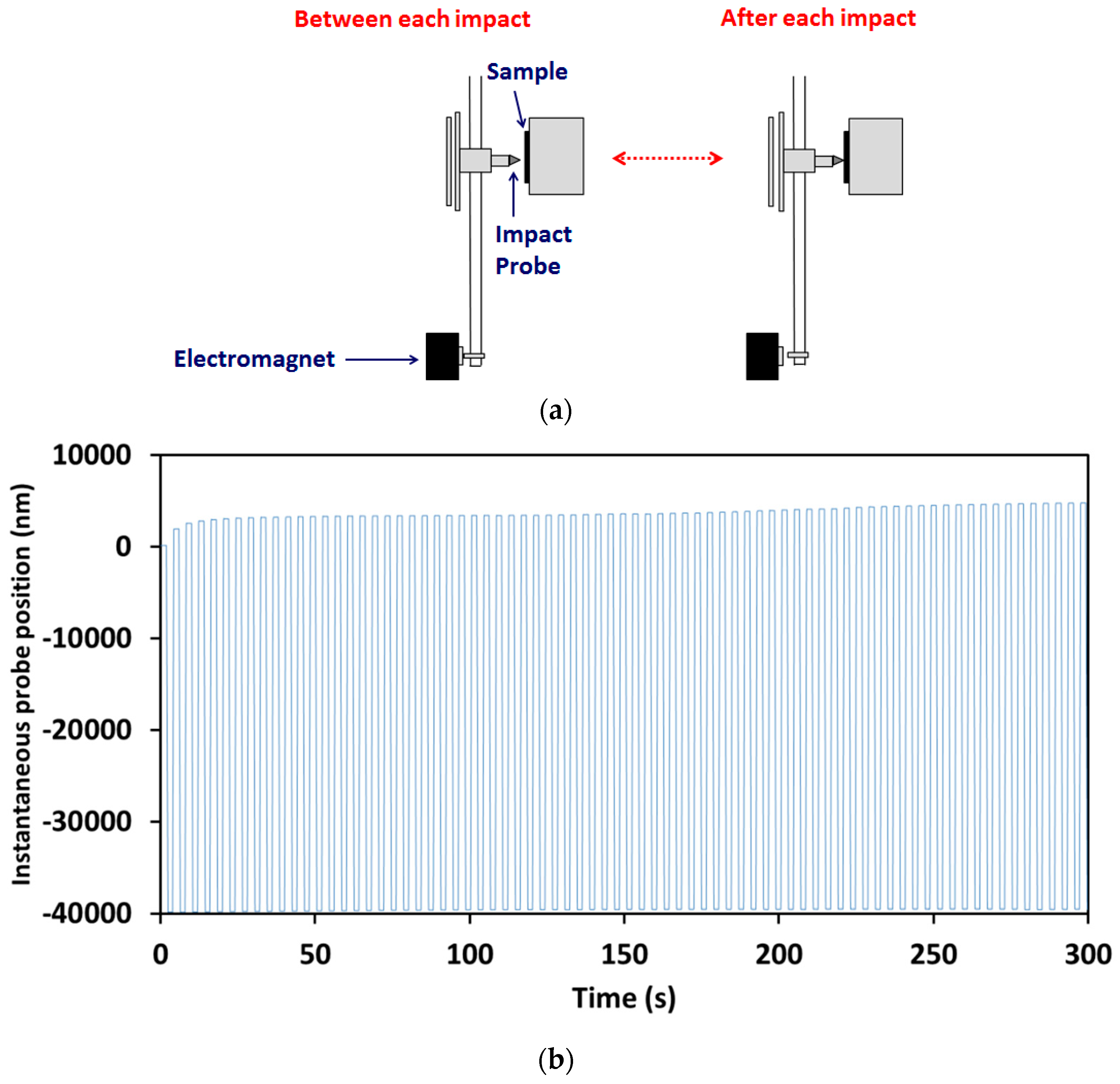
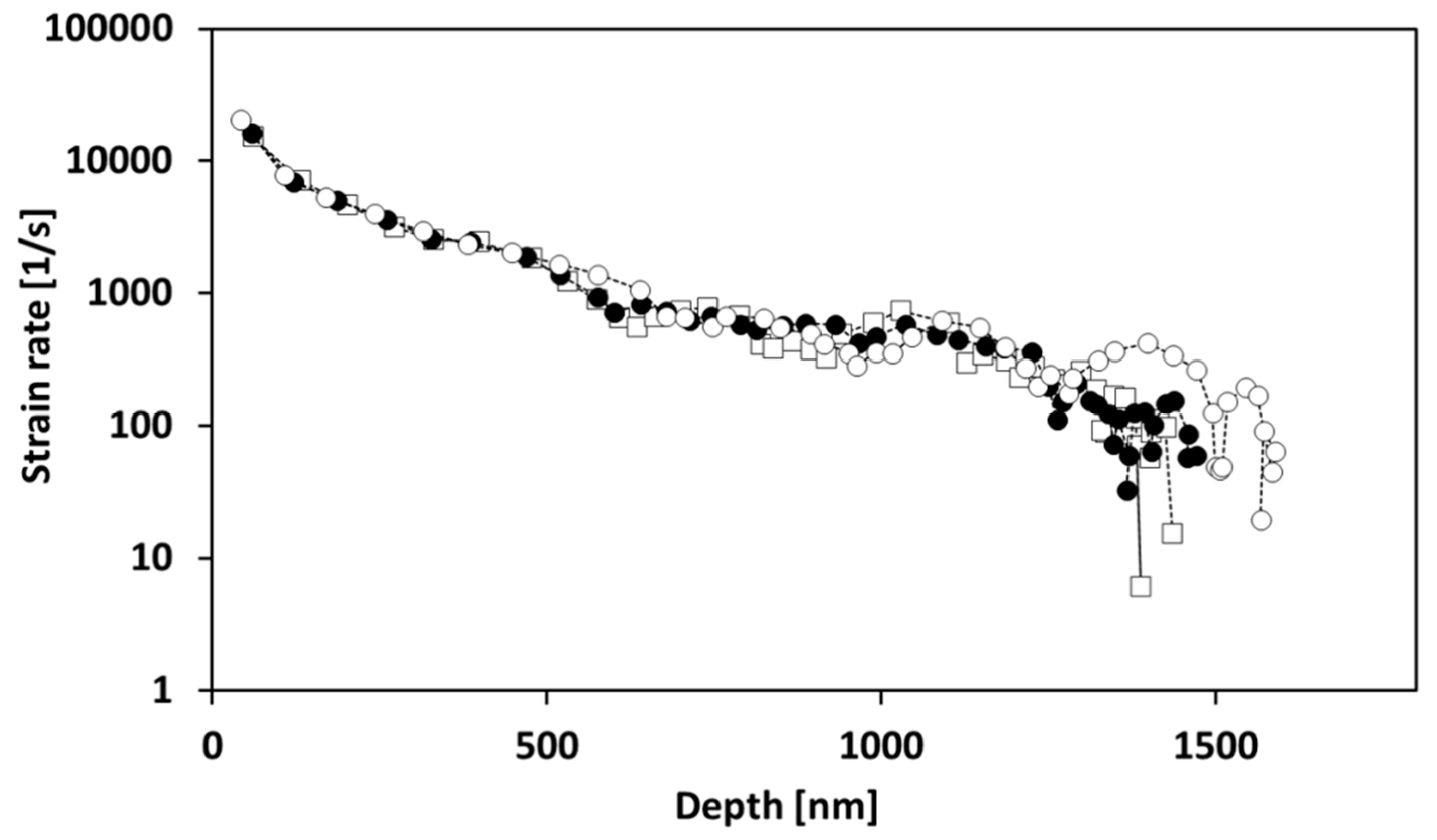
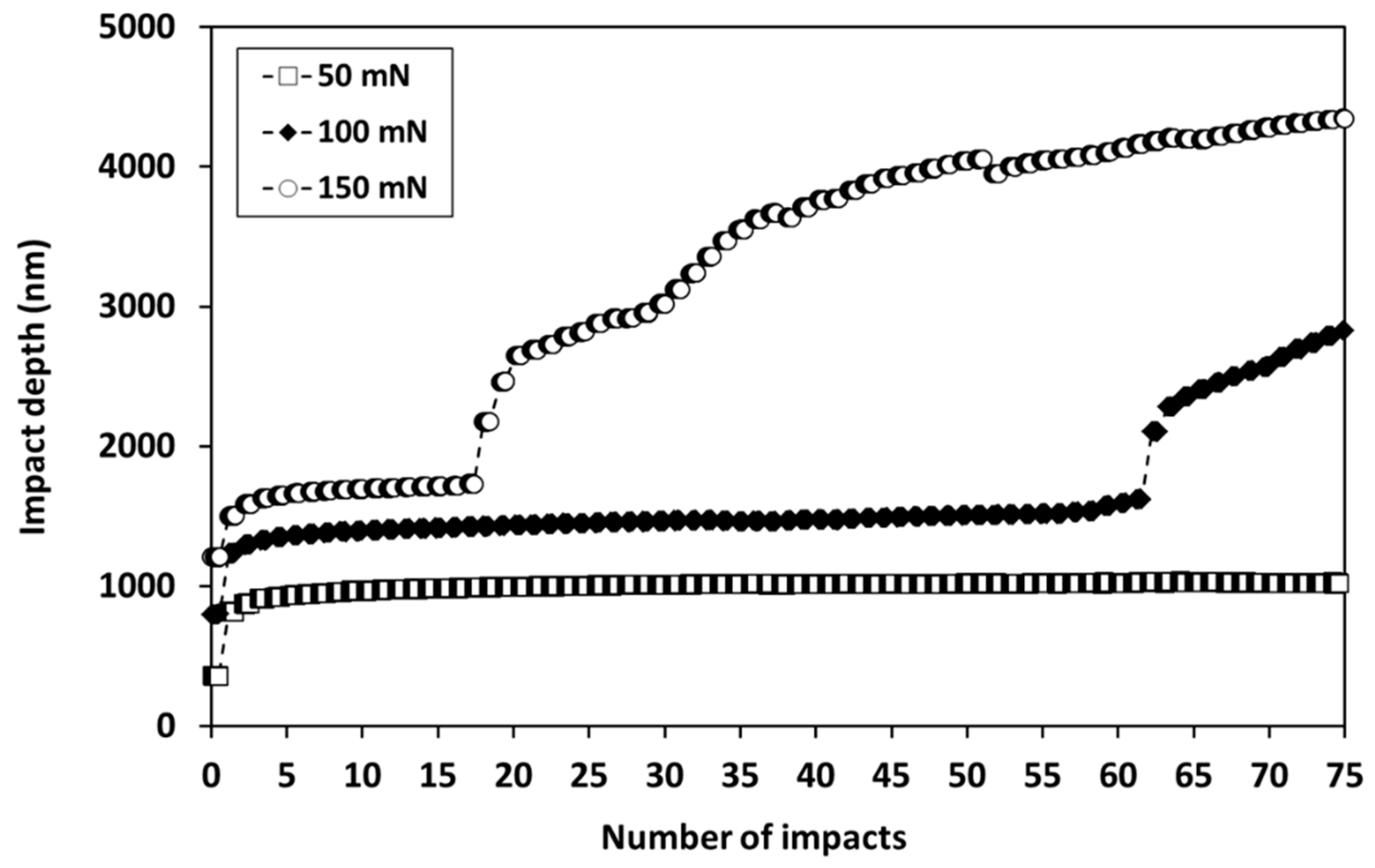
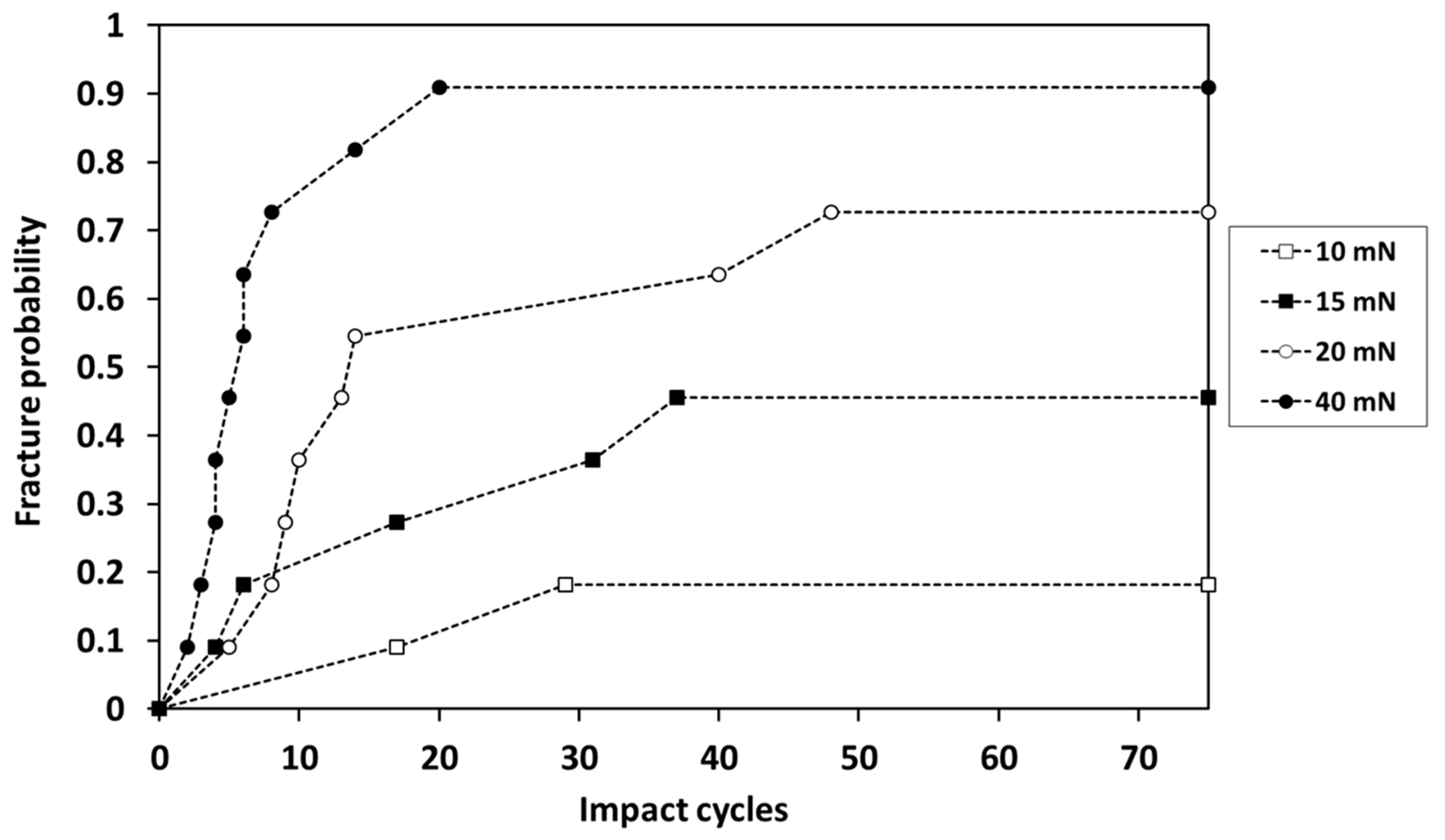
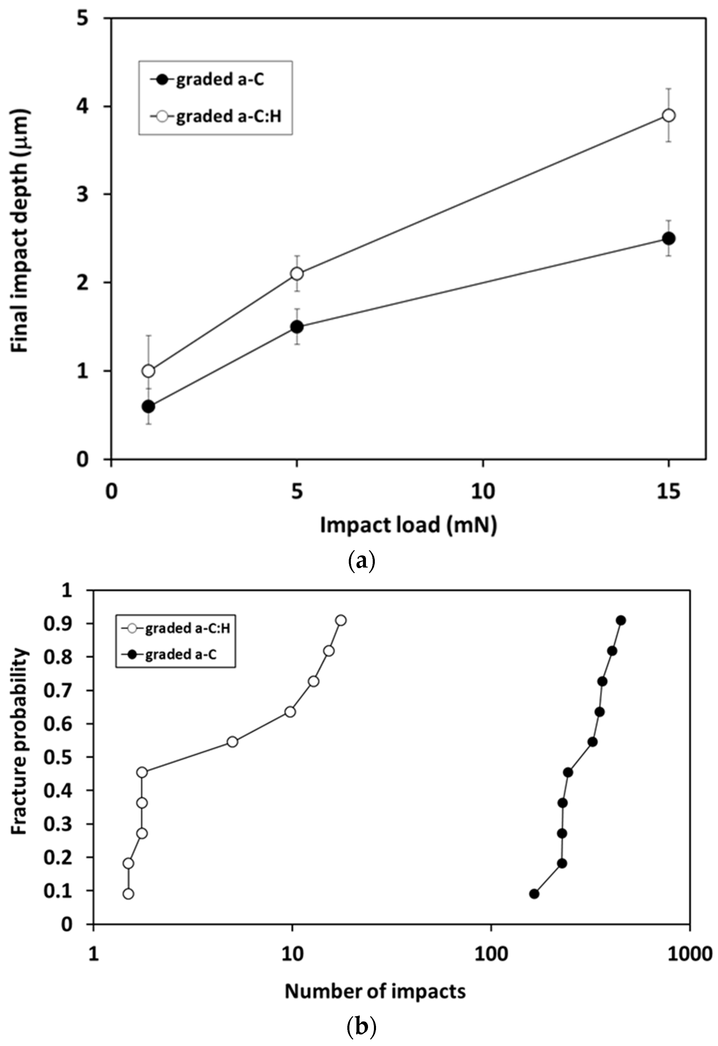
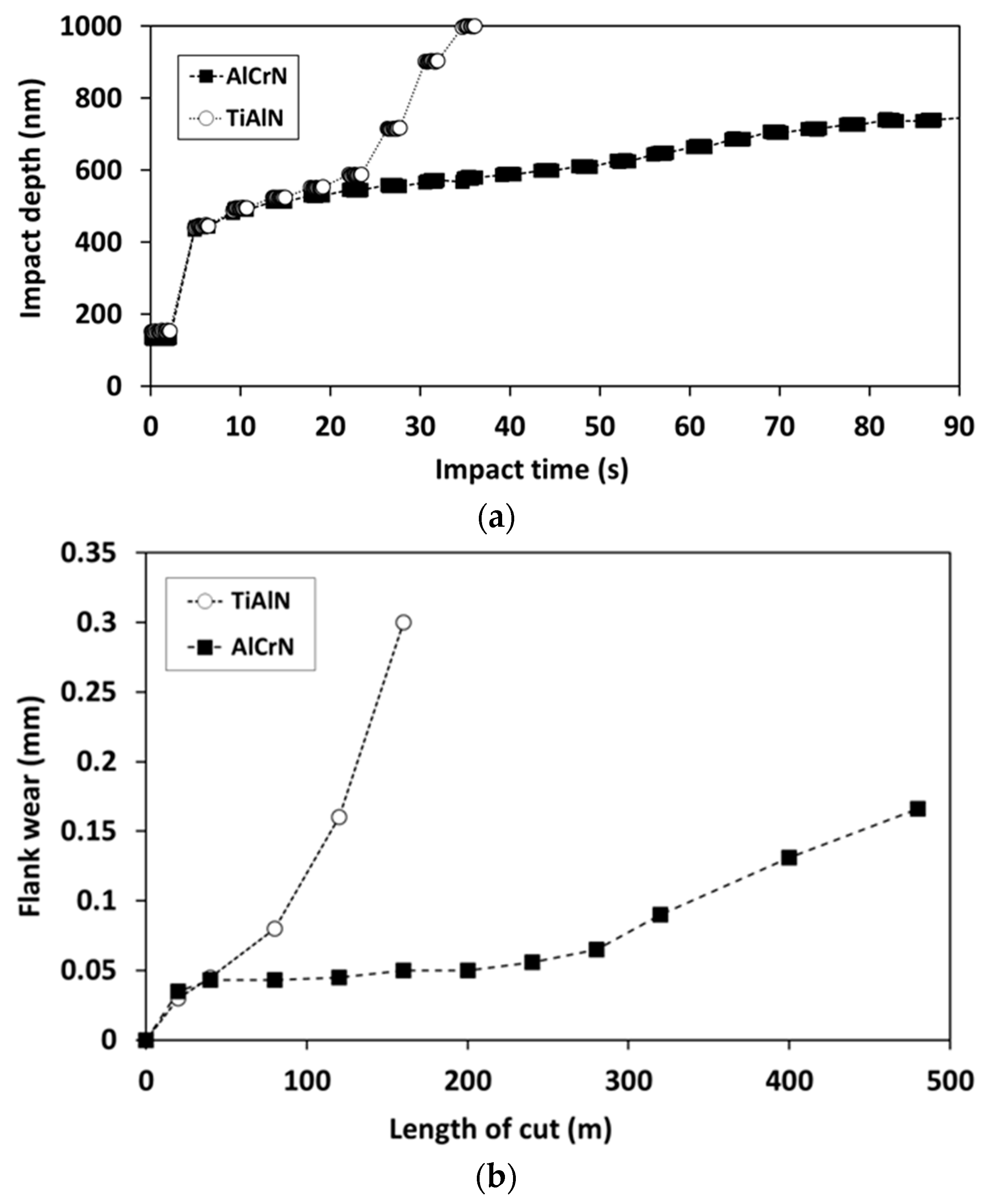
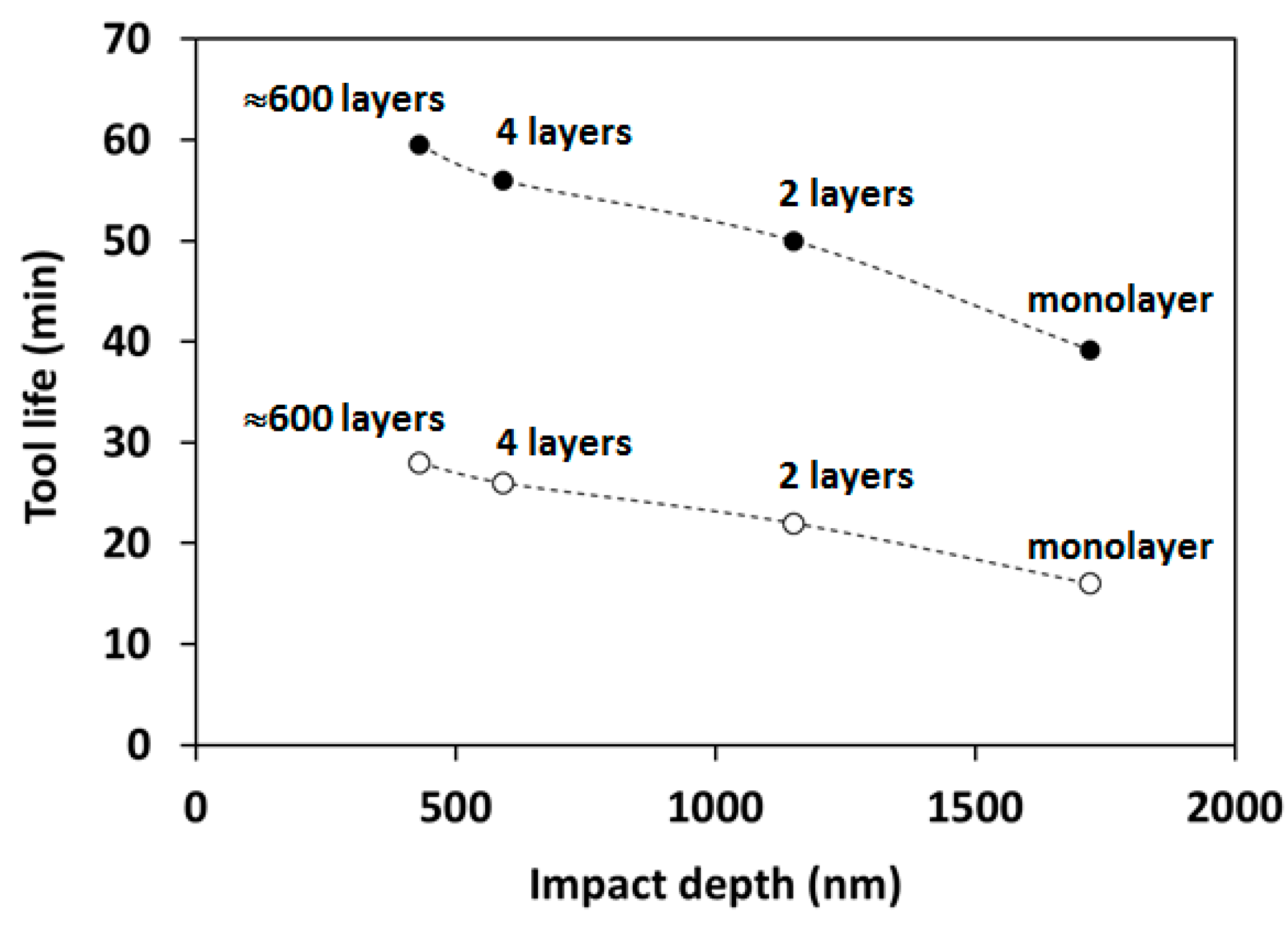
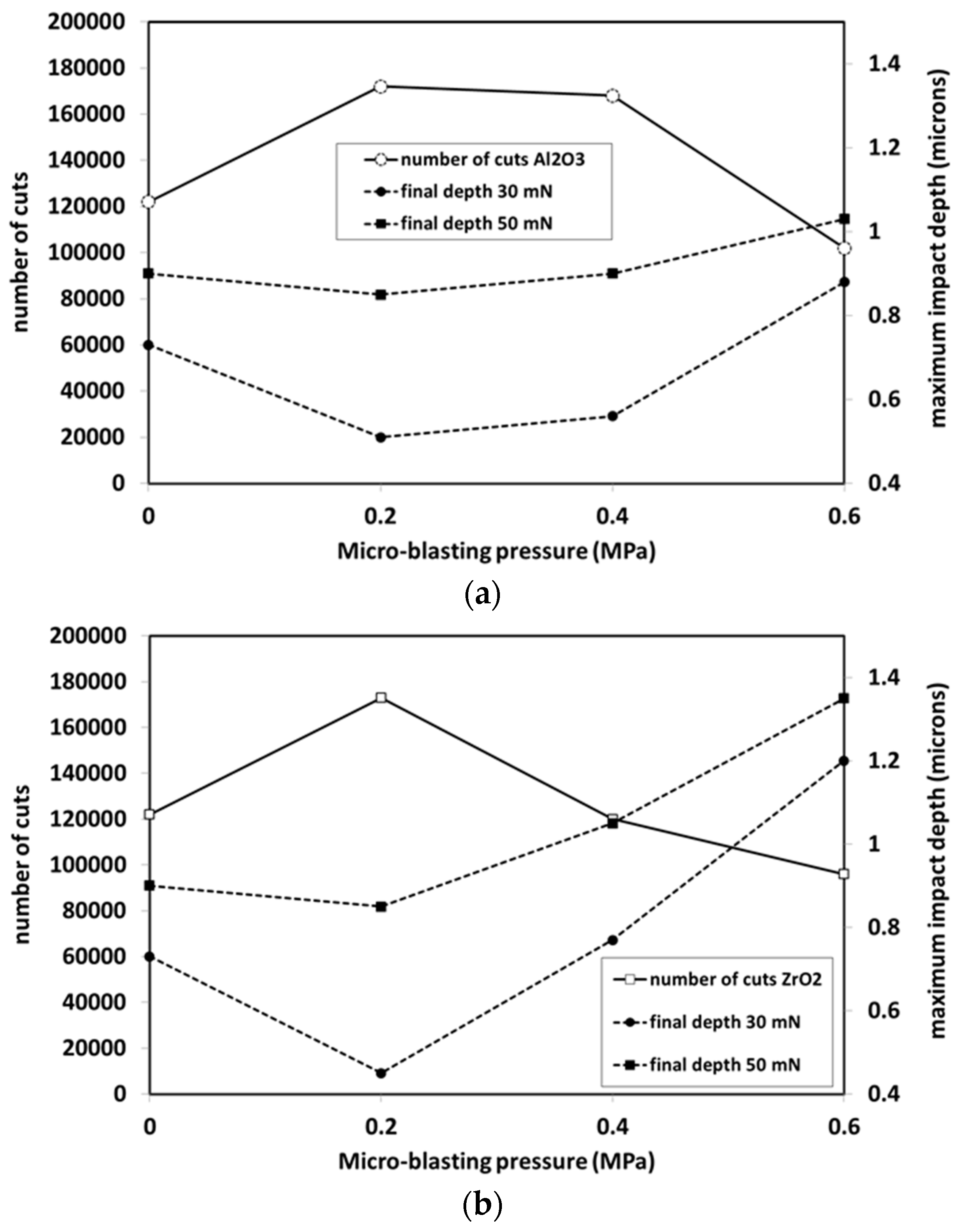
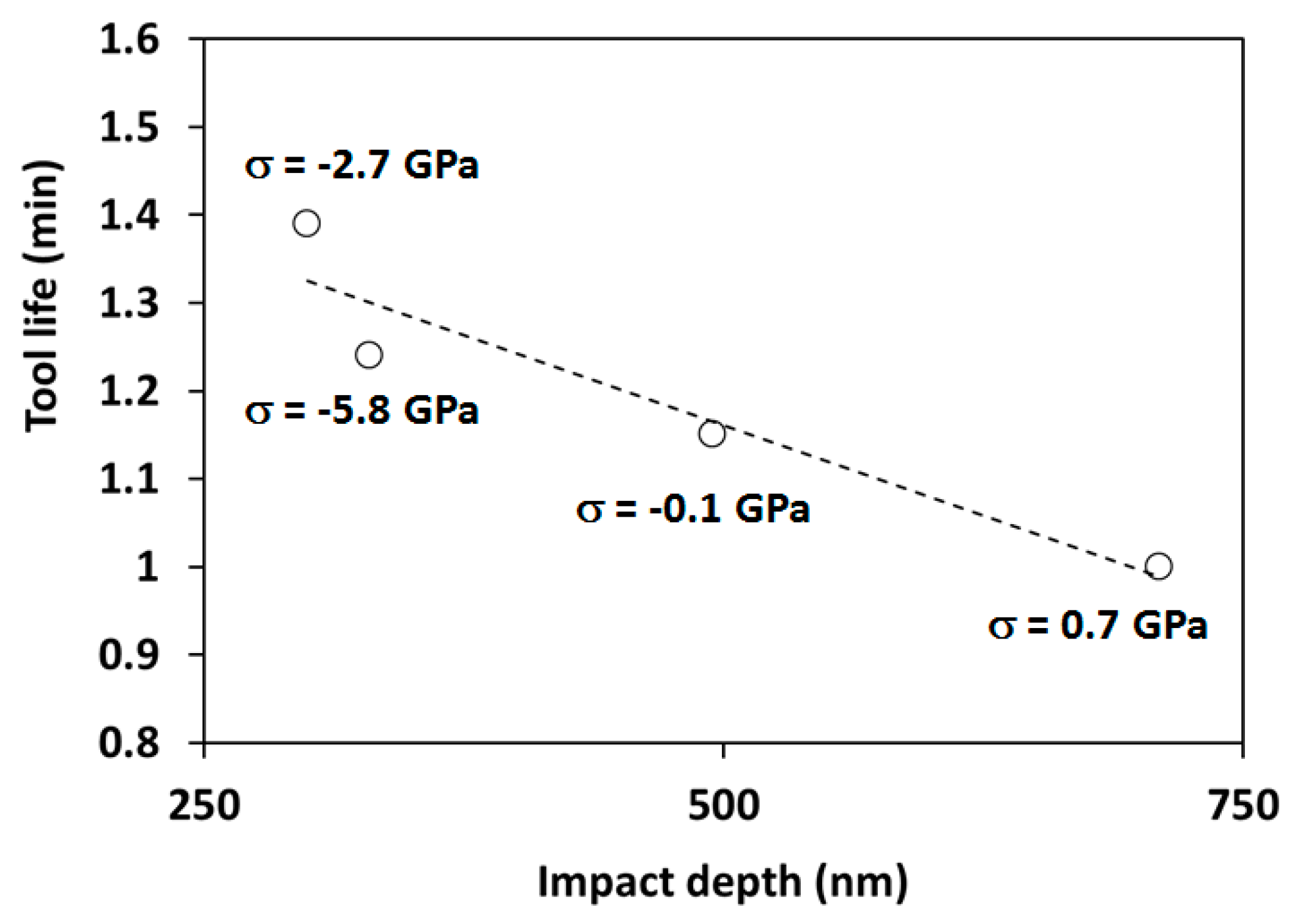
Table 1.
Comparison between nano-, micro- and macro-scale impact test techniques (1).
| - | Nano-Impact | Micro-Impact | Macro-Impact |
|---|---|---|---|
| Depth sensing | Y | Y | N |
| Accurate time-to-failure recorded | Y | Y | N |
| Test duration | 1–60 min (2) | 1–60 min (2) | Extended duration |
| Number of impact cycles | 15–450 | 15–900 | 102–106 |
| Test probe material | Diamond | Diamond | WC-Co, hardened steel, Si3N4 |
| Test probe radius, R | ≈50 nm | 5–100 µm | 1–3 mm |
| t/R | ≈10 | ≈0.1 | ≈0.001 |
| Sensitivity to coating mechanical properties | High | High | may be low |
| Sensitivity to adhesion | Medium | High | may be low |
| Automatic scheduling of multiple tests/tests on multiple samples | Y | Y | N |
| Applied load (N) | 0.001–0.2 | 0.1–5 | >>100 |
| Accelerating distance (μm) | 10–15 | 10–60 | can remain in contact |
Publisher’s Note: MDPI stays neutral with regard to jurisdictional claims in published maps and institutional affiliations. |
© 2022 by the author. Licensee MDPI, Basel, Switzerland. This article is an open access article distributed under the terms and conditions of the Creative Commons Attribution (CC BY) license (https://creativecommons.org/licenses/by/4.0/).
Share and Cite
MDPI and ACS Style
Beake, B.D. Nano- and Micro-Scale Impact Testing of Hard Coatings: A Review. Coatings 2022, 12, 793. https://doi.org/10.3390/coatings12060793
AMA Style
Beake BD. Nano- and Micro-Scale Impact Testing of Hard Coatings: A Review. Coatings. 2022; 12(6):793. https://doi.org/10.3390/coatings12060793
Chicago/Turabian StyleBeake, Ben D. 2022. "Nano- and Micro-Scale Impact Testing of Hard Coatings: A Review" Coatings 12, no. 6: 793. https://doi.org/10.3390/coatings12060793
Note that from the first issue of 2016, this journal uses article numbers instead of page numbers. See further details here.