Article

Influence of Manufacturging Parameters on Microstructure, Chemical Composition, Microhardness, Corrosion and Wear Resistance of ZrC Coatings Produced on Monel®400 Using Laser Processing Technology

1
Institute of Materials Technology, Faculty of Mechanical Engineering, Poznan University of Technology, ul. Piotrowo 3, 61-138 Poznan, Poland
2
Institute of Materials Science and Engineering, Faculty of Materials Engineering and Technical Physics, Poznan University of Technology, ul. Jana Pawła II 24, 61-138 Poznan, Poland
3
Institute of Materials Science, Faculty of Materials Science and Technology in Trnava, Slovak University of Technology, J. Bottu 25, 917 24 Trnava, Slovakia
4
Institute of Mechanical Technology, Faculty of Mechanical Engineering, Poznan University of Technology, ul. Piotrowo 3, 61-138 Poznan, Poland
*
Author to whom correspondence should be addressed.
Coatings 2022, 12(5), 651; https://doi.org/10.3390/coatings12050651
Submission received: 9 April 2022 / Revised: 30 April 2022 / Accepted: 7 May 2022 / Published: 10 May 2022
(This article belongs to the Special Issue Application of Coatings in Industry and Means of Transport)

Abstract

:
This paper presents the influence of production parameters and analysis of ZrC coatings production on Monel®400 substrate. The effects of laser beam power on the microstructure, chemical composition, corrosion resistance and on selected mechanical properties such as microhardness and wear resistance were investigated. The investigation consisted of the production of composite coatings using laser processing of pre-coatings made in paste form on a nickel based alloy (Monel®400). In the studies, a diode laser with a rated power of 3 kW was used. The laser processing was carried out using a constant laser beam scanning speed of 3 m/min and three different laser beam powers: 350, 450, 550 W. It was found that it is possible to form composite coatings on a nickel-copper alloy substrate, where the matrix is made of nickel-copper based alloy from substrate and the reinforcing phase is ZrC. Investigation was carried out for single and multiple laser tracks. Based on the studies it was found that reinforcing phase content decreased as laser beam power increased. A similar relationship was found for all the other investigated properties such as microhardness, corrosion resistance, and wear resistance. As laser beam power increases, the microhardness of the Ni-Cu-based matrix decreases. However, is still greater than for the Monel®400 substrate. It was found that the amount of hard carbide phases in the Ni-Cu-based matrix affects the corrosion and wear resistance of the coatings.

1. Introduction

Modern manufacturing technologies used in metal industry use high energy sources such as laser beam or plasma [1,2,3,4,5,6,7,8]. These heat sources are used in processes as such as laser [1,2,3,4,7,8,9] or plasma [5,6,7] remelting, hardening [1,2,3,4,10], laser alloying [10,11,12,13,14,15] or laser cladding [16,17,18,19,20,21,22,23,24]. These processes have been widely used in the surface treatment of tools or machine parts [1,3,19]. The use of a laser beam does not only apply to ferrous alloys such as steel and cast iron [11,12,13,14,15,16,22,25]. At present, laser processing of non-ferrous alloys (mainly nickel, copper and cobalt alloys) is more and more common and interesting [9,10,17,18,19,20,21,23,24,26]. In certain cases, the techniques of laser surface modification have become a very good alternative to replace conventional heat treatment methods, hence their increasing popularity in industrial applications [1,3]. Laser surface modification is used in the production of hard coatings in mining or for agricultural tools [19]. There is then no need to use heat treatment on the entire tool. The cutting edges of the tool are protected with a coating containing hard carbides, which greatly improves its durability. The most commonly used reinforcing phases are tungsten carbides (WC) and (W2C) [5,14,16,19,27,28], silicon carbides (SiC) [20,29,30], boron carbides (B4C) [15,21], titanium carbides (TiC) [13,22] and tantalum carbides TaC [14,17,23]. The coatings obtained in the process of laser surface modification can take the form of composites. Much less attention is given to other types of carbides, for example ZrC [25,30]. This type of carbide is one of the ingredients used in the production of cermets because it has a very high hardness. There is also a clear lack of publications on surface treatment of non-ferrous alloys (including Monel®400) using this carbide. Most of the work concerns either ZrC coatings made on other materials, or modification of Monel alloys with other types of carbides. Technologies that use various sources of high energy are quite common in the treatment of nickel alloys [31]. In the paper by [27,28], the authors analysed whether Monel®400 alloy properties could be improved using the laser engineered net shaping methods (LENS). The authors used two methods. In the first the alloy was deposited onto a heated substrate. In the second the alloy was subjected to laser remelting of the final deposited layer. The researchers observed multiple microstructures with eutectic, fishbone, and Fe/W-rich dendrites. They stated that surface hardness of the laser remelted alloy was found to be higher compared to the other alloys. In a paper [24], the authors studied the microstructure and properties of laser cladded in-situ ZrB2-ZrC/Cu composite coatings on copper substrate. The results indicated that the in-situ ZrB2 ceramic had a needle-like morphology. The submicron particle phases (ZrC) had a rectangular morphology in the copper matrix. The hard ceramic fibres and particles that were synthesized in situ were dispersed homogeneously in the metal matrix, which improved mechanical properties of the coating. A paper [25] presents the study of the Fe/ZrC coatings produced on steel using laser processing. The author stated that it is possible to create composite coatings on a steel surface when the matrix is made of iron-based alloy and the reinforcing phase is ZrC. He also showed that the reinforcing phase content and microhardness decreased as laser beam power increased, and the amount of hard carbide phases in the iron-based matrix affects the total hardness of the coatings. Ceramic materials such as ZrC and ZrN are of interest in the application of materials in extreme high temperature environments, particularly for nuclear applications in generation IV reactors. In a review paper, [32] presents the current available data for the properties of ZrC, ZrN and mixed carbonitride phases and identifies causes of scatter in the literature and areas requiring further research. In a study by [33], the authors carried out the selective laser melting for the preparation of an ultra-high temperature ceramic coating. To prepare ceramic coatings, ZrB2, ZrC, and B4C powders were used, which were applied on a metallic tungsten substrate by using laser powers between 200 and 400 W.
Due to the fact that in the literature there are few reports on ZrC coatings produced by laser processing, this issue seems to be interesting and worthy of attention. There are also few publications on the use of nickel alloys as a matrix for such types of reinforcement phase. Therefore, it is worth taking a closer look at such issues as how the bond between the matrix and the reinforcement phase affects the microstructure and the properties of the resulting composite coating. In this study, the authors analyzed properties of the composite coating obtained as a result of laser surface modification of the Monel®400 substrate by ZrC. In this work, the authors highlighted the effect of hard ZrC powder particles on increasing the wear resistance of this alloy, while checking the corrosion resistance of the produced coatings.

2. Materials and Methods

ZrC coatings were produced by laser processing technology on a Monel®400. Before the action of the laser beam, the ZrC pre-coat in the form of a paste was applied on substrate. The prepared paste consisted of ZrC powder, distilled water and water glass used as a binder. Chemical composition of substrate material is given in Table 1. The specimens were in a cubic form, with dimensions of 10 mm × 10 mm × 10 mm.
The shape and size of ZrC powder particles were observed using scanning electron microscopy (SEM, TESCAN, Brno, Czech Republic) and are presented in Figure 1. The average particle size (APS) was <15 µm, which was in accordance with the delivered certificate. The powder purity was 99.9%. All presented parameters were in accordance with the producer data (Sigma-Aldrich, St. Louis, MO, USA).
In the first step of the experiment, ZrC paste was applied on the Monel®400 substrate, thereby forming a pre-coat. These pre-coats were prepared by mixing 18 g of ZrC, 3 mL of sodium water glass and 3 mL of distilled water. The consistency of paste must be appropriate for its application with a brush without any problems. Thus, it must adhere evenly and tightly to the substrate material. During these tests, every effort was made to ensure that the pre-coat thickness fluctuated by around 200 μm. Due to the method of applying the pre-coat with a brush, there were some deviations, but they usually did not exceed 10 μm. To ensure that the appropriate specimens were submitted for further laser processing, the thickness of each of the pre-coats was measured using an ultrasonic thickness gauge (Elcometer company, Manchester, UK) after drying pre-coats. The microstructure as well as EDS mapping of the pre-coat are shown in Figure 2.
The distribution of ZrC powder particles in the pre-coat produced is uniform and the coating itself adheres well to the substrate. In the pre-coat, no defects were observed, such as large gas porosities or discontinuities. In order to make the pre-coat more homogeneous and to reduce the occurrence of ZrC powder agglomerates, the paste was mechanically mixed using a laboratory stirrer, and the paste container was additionally placed in an ultrasonic cleaner, which caused the breaking of powder clusters. Only after obtaining a homogeneous paste consistency was it applied to the Monel®400 alloy substrate. The substrate was cleaned and degreased with acetone.
In the second step of the experiment, the specimens thus prepared were subjected to laser processing (laser alloying). These processes were performed using aTruDiode 3006 (TRUMPF, Ditzingen, Germany) diode laser with a rated power of 3 kW. The laser working head was integrated with a KR16-2 robot arm (KUKA, Augsburg, Germany) in order to position the laser beam. During these processes, a constant laser beam velocity (v) of 3 m/min was applied. The laser beam power (P) was changing and was as follows 350, 450, 550 W, respectively. The diameter of the laser beam was 1 mm and the transverse electromagnetic mode in this laser device was TEM00. The wavelength of the laser beam was 1040 nm. The applied laser beam powers and the constant diameter of the laser beam gave laser beam power densities (q) of 45, 57, and 70 kW/cm2, respectively.
A laser processing scheme is presented in Figure 3. As a result of laser beam action, the ZrC pre-coat was mixed with the Monel®400 substrate, and as a consequence a new composite coating characterized by properties different from the substrate was obtained. The laser processing was conducted using both single and multiple laser tracks. The scheme of the single track process is presented in Figure 3a, and for multiple tracks in Figure 3b. The process of multiple track production consisted in moving a laser beam from point A to B and turning off the laser and then returning the laser head from point B to point A. In the next step, the laser head was transferred by a distance of 0.5 mm from point A to point C, and then (where the laser beam started) from point C to D. This activity was repeated until the entire surface of the specimen was covered by ZrC coating. For a multiple laser track process, the distance between the laser track axes was designed to obtain a 50% overlapping.
Microstructure observations were carried out on specimen cross-sections perpendicular to the produced coatings using two models of Schottky Field Emission Gun Scanning Electron Microscopes (FEG SEM): MIRA3 (TESCAN, Brno, Czech Republic) as well as JSM-7600F (Jeol Ltd., Tokyo, Japan). The observations were also made using the Eclipse MA200 light microscope (Nikon, Tokyo, Japan). Both scanning electron microscopes were equipped with an energy dispersive spectrometer (EDS) and dedicated software. Prior to observation, all specimens were ground with papers with grit from 120 to 1200, polished using diamond paste (diamond particle sizes 1 μm) for 10 min and then aluminium oxide (AP-D Powder 0.05 µm) for 10 min, and finally etched in Marble’s solution for 10 s. Microhardness tests were carried out on cross sections perpendicular to coatings along laser track axes. A FM-810 microhardness tester (Future-Tech, Kawasaki, Japan) equipped with FT-Zero automatic indentation measuring software was used. Microhardness tests were made under an indentation load of 50 g, while loading time of each measurement was 15 s. Corrosion resistance tests were carried out using a ATLAS 1131 EU&IA potentiostat-galvanostat device (Atlas-Sollich, Rębiechowo, Poland) in 3.5% NaCl aqueous solution. The potentiodynamic method of anodic polarization curves was applied. Corrosion tests were performed at a constant temperature 22 °C and using a sweep rate of 1.0 mV/s. The reference electrode was a saturated calomel electrode, and the auxiliary electrode was a platinum electrode. In these studies, corrosion potential and corrosion current of analyzed ZrC coatings were determined. Wear resistance tests were conducted on the plate-shaped specimens using an Amsler-type device (MBT, Poznan, Poland). The ring-shaped counter-specimens were made of C45 steel after hardening from 850 °C in water and tempering at 550 °C for 1 h. Wear resistance tests were performed in dry friction conditions using the following parameters: rotation speed of counter-specimen 250 rev/min, force pressure on the specimen 98 N as well as a friction time of 60 min. The mass loss of specimens was measured using the AS220.R2 analytical balance (RADWAG, Radom, Poland) after every 10 min of friction. After wear tests, the 3D surface topography and roughness profiles reconstruction were determined based on SEM images and were analyzed using Mountains® SEM software (Digital Surf Headquarters, Besançon, France).

3. Results

3.1. ZrC Coatings on Monel®400—Single Laser Tracks

3.1.1. Microstructure and Chemical Composition of Single Laser Tracks

Figure 4, Figure 5, Figure 6, Figure 7, Figure 8 and Figure 9 show microstructures of ZrC coatings produced on the Monel®400 alloy with a laser beam. Single laser tracks were made to test whether it would be possible to produce coatings. In each case analyzed, it was found that it is possible to create a coating characterized by a composite structure in which the matrix becomes a Ni-Cu alloy substrate, and the reinforcing phase are ZrC particles. Considering all of the parameters used, it can be concluded that the dimensions of the melted zone of individual tracks increase with increasing laser beam power. The width of the remelting increases to a much lesser extent, while quite significant changes were observed in track depths. Track depth measurements were made on their axes. When using a laser beam power of 350 W, the track depth (thus coating thickness) was 115 µm. Increasing the power of the laser beam to 450 W increased the thickness of the coating to 143 µm, and to 550 W—up to 210 µm. In all the analyzed cases it was observed that the entire thickness of the pre-coat produced is involved in the formation of a composite coating, which is formed from the substrate line towards the core of the material. The ZrC powder particles present in the pre-coat are somehow transferred to the substrate as a result of the heat and Marangoni effect and form a composite coating. The process is different in powder cladding [8], where the coating is formed partly at the substrate line, but it grows, increasing sample dimensions. Figure 4a–d show a single coating track produced with a laser beam power of 350 W. The entire view of the coating (Figure 4a), and its individual zones (subsurface—Figure 4b, middle—Figure 4c and sub substrate—Figure 4d) are presented. Carbide agglomerates formed during the remelting of the pre-coating are visible throughout the entire area of the remelted zone despite the fact that they were not present in the pre-coating. These agglomerates are most likely the result of mixing ZrC particles with substrate material due to fluctuating forces generated by the laser beam. Agglomerates can be divided into two types.
Figure 4. Microstructure of ZrC coating produced on Monel®400 alloy after being obtained by laser processing using laser beam power 350 W: (a) view of the entire remelted zone, (b) subsurface zone, (c) middle zone, (d) sub substrate zone.
Coatings 12 00651 g004
One type is made of tightly adhering ZrC powder particles, and the other is characterized by the fact that a remelted matrix is visible amid the ZrC powder particles. Observing the microstructure of the coating, it can be concluded that agglomerate forming occurs mostly in the middle part of the coating (in track axes). This is probably related to the effect of Marangoni convection movements. Movements of liquid metal in the outer part of the pool are much faster than inside the pool, which causes the ZrC particles to move towards the laser track centre. This is further facilitated by a lower ZrC particle density (6.7 g/cm3) compared to that of the Monel®400 alloy (8.8 g/cm3). The melting point of ZrC is 3532 °C, while the melting range of the Monel®400 alloy is 1300–1350 °C. This is a considerable difference, which means that at low laser beam powers it is possible to achieve complete substrate remelting. However, a low laser beam power is associated with a small amount of heat supplied to the pre-coating and thus to the carbides. Such power is not sufficient to completely dissolve carbides of every size. Very small ZrC particles remelt completely, while larger ZrC powder particles melt on the surface only. However, this is sufficient to combine the particles with the other particles in the agglomerate or with the Ni-Cu matrix. The microstructure of the subsurface zone of the ZrC coating produced with a 350 W laser beam power is characterized by a matrix enriched with a multitude of small carbides of polygonal shapes (mainly cubes) and large ZrC particles, either occurring alone or in agglomerates. The microstructure of the central zone is characterized by a gradual disappearance of fine polygonal carbides. The microstructure of the matrix changes completely when the coating is bonded to the substrate. The structure of equiaxed and columnar crystals are visible there, and the front of the coating crystallization is visible on the very connection. Differences in dendrite lengths are associated with a privileged orientation of their growth, which may vary in different areas of laser tracks. This is dependent on the solidification rate. Hence, in the analyzed samples, a clear transition from a flat crystallization front associated with concentration overcooling to cellular and then a cellular-dendritic structure can be seen. With a sufficiently large overcooling, the cell type may change and second-order branches characteristic of dendritic growth appear. Due to the presence of carbide, the growth orientation may change. It can therefore be concluded that in the analyzed laser track there are areas of microstructures corresponding to higher and lower cooling rates. A higher cooling rate is close to the substrate and where there are no agglomerates. A lower cooling speed of the matrix is observed in the area of agglomerate occurrence, which is associated with heat transfer by carbides.
Figure 5 shows individual areas of the laser track at high magnification, obtained at a laser beam power of 350 W. Yellow squares mark the places where the chemical composition (EDS) was tested. The results of these studies are given in Table 2. The middle part of the coating is shown (Figure 5a), as well as the part near the substrate, including the matrix microstructure (Figure 5b) and agglomerate area (Figure 5c). In the upper part of the middle zone, there are precipitates in the shape of squares and rectangles. Their sizes range from 200 to 600 nm. In a selected area of the agglomerate the presence of a fine, nanometric dendritic structure was found. It is a crystallized matrix acting as a connection between individual grains of remelted ZrC particles.
Figure 5. Microstructure of remelted zone of ZrC coating produced on a Monel®400 alloy after being obtained by laser processing using a laser beam power 350 W: (a) middle zone, (b) matrix of sub substrate zone, (c) ZrC agglomerate in sub substrate zone.
Coatings 12 00651 g005
Figure 6a–d show a single track of the ZrC coating produced with a laser beam power of 450 W. Figure 6a shows a view of the entire coating, and subsequent figures show individual zones (subsurface Figure 6b, middle Figure 6c and sub substrate Figure 6d). It can be seen that an increase in laser beam power contributed to a more uniform mixing of ZrC particles with the matrix material. A reduced amount of compact agglomerates was observed in comparison to the coating produced at a laser beam power of 350 W. More individual ZrC powder particles can be seen. The microstructure of the matrix was also changed. Providing more heat resulted in an increase in the size of columnar and equiaxed crystals. These structures are already visible in the subsurface zone. A good bonding of the coating with the substrate was found, and a cellular structure was observed in the remelted zone near the boundary with the substrate. The increase in laser beam power may have increased the extent of remelting and the partial remelting of ZrC particles, however, due to the fact that a powder of different grain sizes was used; this cannot be unequivocally stated.
Figure 6. Microstructure of ZrC coating produced on Monel®400 alloy after obtained by laser processing using a laser beam power 450 W: (a) view of the entire remelted zone, (b) subsurface zone, (c) middle zone, (d) sub substrate zone.
Coatings 12 00651 g006
Figure 7 shows individual areas of the laser track at high magnification, obtained at laser beam power of 450 W. The results of chemical composition from the yellow areas squares mark are given in Table 2. As in the case of a laser beam power of 350 W, small size carbide precipitates were also found; however, they were in a much smaller amount. (Figure 7a,b). In a micrometric cell structure (Figure 7c), the presence of bright precipitates in the form of a mesh surrounding the cell was observed. The image was taken in BSE contrast, so it can be concluded that this is a carbide mesh.
Figure 7. Microstructure of remelted zone of ZrC coating produced on a Monel®400 alloy after being obtained by laser processing using a laser beam power of 450 W: (a) subsurface zone, (b) middle zone, (c) sub substrate zone.
Coatings 12 00651 g007
A similar series of photos was taken for coatings produced using a 550 W laser beam power. These photos are shown in Figure 8a–d and successively present the entire coating (Figure 8a) subsurface zone (Figure 8b, subsurface zone in magnification (Figure 8c) and the middle and subsurface (Figure 8d). Increasing the power by another 100 W resulted in a decrease in agglomerate share and size (Figure 8b), and an increase in the number of small carbide precipitates (Figure 8d). Within the coating, however, a fairly large amount of microporosity was observed, which may have resulted from applying too high a temperature during the process.
Figure 8. Microstructure of ZrC coating produced on a Monel®400 alloy after being obtained by laser processing using a laser beam power 550 W: (a) view of the entire remelted zone, (b) subsurface zone, (c) enlargement of the subsurface zone, (d) middle and sub substrate zones.
Coatings 12 00651 g008
Figure 9 shows respective enlarged areas of the remelted zone for the track produced at a laser beam power of 550 W. The results of chemical composition from area yellow squares mark are given in Table 2. A subsurface zone is shown (Figure 9a), as well as the middle zone (Figure 9b) and the zone closest to the bonding of the coating with the substrate (Figure 9c). With increasing distance away from the substrate, the amount of fine carbide precipitates decreases. An increase in the dimensions of the cellular structure was found, which was caused by an increase in laser beam power and thus an increase in the amount of heat supplied.
Figure 9. Microstructure of remelted zone of ZrC coating produced on Monel®400 alloy after obtained by laser processing using laser beam power 550 W: (a) subsurface zone, (b) middle zone, (c) sub substrate zone.
Coatings 12 00651 g009
For samples with single tracks, EDS tests of chemical composition were carried out. The analysis included both Zr as an element forming the reinforcement phase and the basic components of Monel®400 alloy, i.e., nickel and copper. Figure 10 shows EDS mapping for entire coatings, and Figure 11 for magnified areas of the remelted zone. In each of the analyzed cases, the presence of agglomerates enriched with zirconium (ZrC particles) was confirmed. The influence of laser beam power on distribution of these agglomerates in the coating was also confirmed. It is clearly seen that at low powers Zr is observed mainly in the axis of the track whereas with power increase the distribution of Zr is more uniform. Laser remelting of the Monel®400 alloy did not affect the segregation of nickel and copper in any way. These elements are uniformly distributed.
Figure 11 shows EDS mapping for laser tracks of coatings produced using 350 W (Figure 11a), 450 W (Figure 11b) and 550 W (Figure 11c). Carbon is marked on these maps to show that large grain areas correspond to the occurrence of ZrC. Table 2 presents the results of chemical composition (EDS) on areas shown in Figure 5, Figure 7 and Figure 9 as yellow squares marked with numbers from 1 to 5.

3.1.2. Microhardness of Single Laser Tracks

Figure 12 shows microhardness profiles for ZrC coatings produced with three different laser beam powers. Microhardness of the carbide-enriched matrix decreases slightly as the laser beam power increases. This is due to the rising share of the substrate in the coating. Microhardness values decrease from 600 HV0.05 for the coating produced at 350 W laser beam power to about 400 HV0.05 for the ZrC coating produced using a 550 W laser beam power. Higher microhardness values shown on the graph are due to the fact that the measurement was made in the area of occurrence of ZrC agglomerates. The ZrC itself has a hardness exceeding 2500 HV, but the agglomerates, due to the fact that they are partially contained in the matrix, display lower hardness. It was found that the hardness of agglomerates ranges from approximately 1200 HV0.05 to about 2000 HV 0.05. As the hardness of the analyzed Monel®400 alloy was approximately 200 HV0.05, it can be concluded that each of the coatings produced resulted in an increase in surface hardness.
Figure 13 shows a photograph depicting selected microhardness measurements and confirming the impact of agglomerates on coating hardness. As can be seen, the hardness measured in the sample agglomerate was 1448 HV, whereas in the vicinity of another, much smaller and more dispersed agglomerate it was only 473 HV. When there were no agglomerates within the matrix, the hardness was only about 320–360 HV, which was still higher than substrate hardness.

3.2. ZrC Coatings on Monel®400—Multiple Laser Tracks

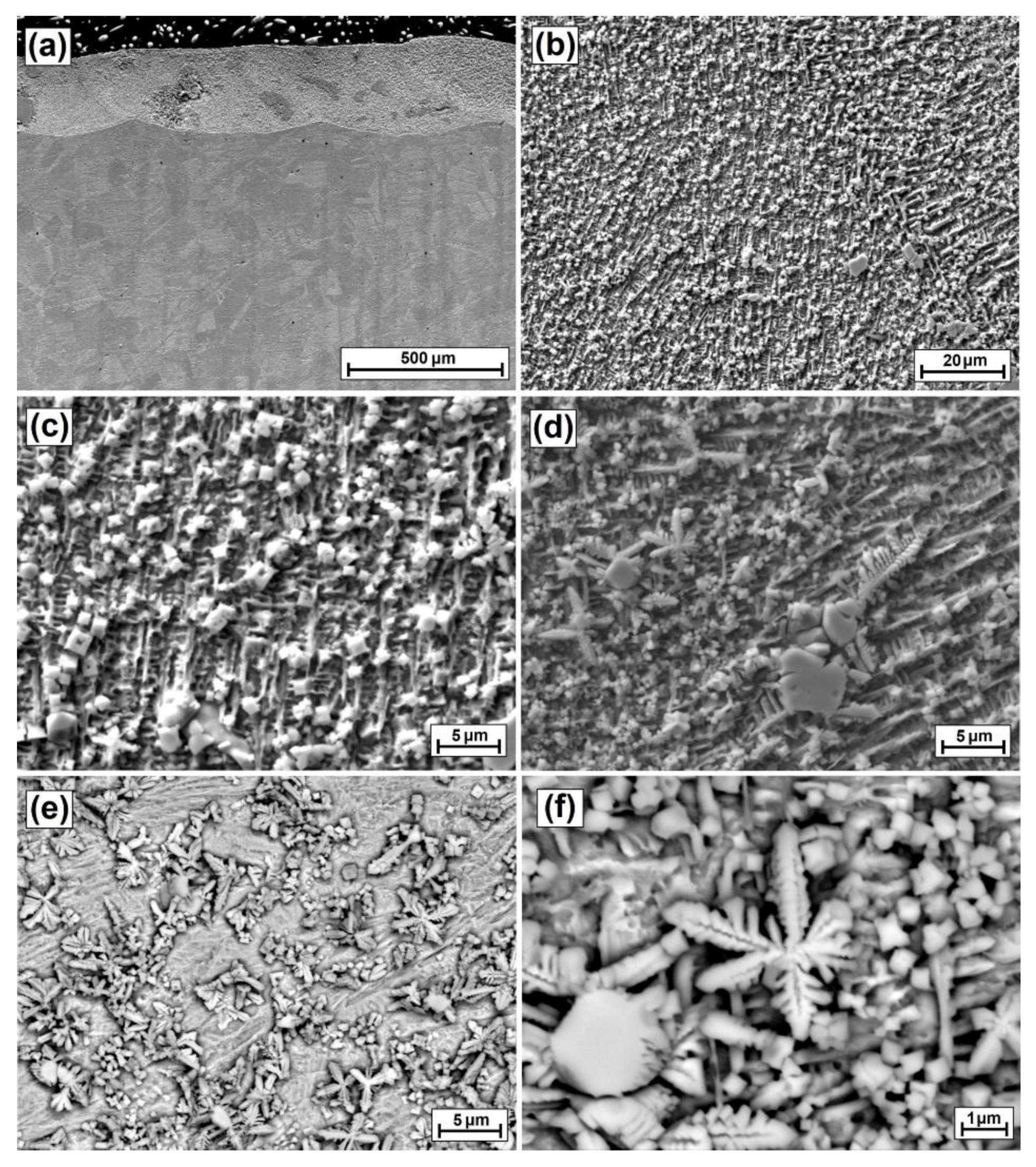
3.2.1. Microstructure and Chemical Composition of Multiple Laser Tracks

After initial analysis of single tracks, multiple laser tracks were made using the same laser beam power parameters, i.e., 350, 450 and 550 W. The aim of the study was to check the possibility of producing a composite ZrC coating on the entire sample surface and to analyze correlations between single laser tracks. Figure 14, Figure 15 and Figure 16 show the microstructures obtained after laser processing of the ZrC pre-coating in paste form. Figure 14a–f show the microstructure of the ZrC coating produced on the Monel®400 alloy with 350 W laser beam power. The average thickness of the composite coating was 243 µm. This result was obtained on the basis of the arithmetic mean of depths measured in the axis of all laser tracks produced. The applied parameter of track overlapping ensured continuity of the coating; its minimum thickness at the sites of the track combining was 190 µm. It can therefore be assumed that utility thickness of the coating is exactly that. The resulting microstructure differs slightly from the microstructure of ZrC coatings made as single tracks. However, it was observed that the agglomerates are less compact, and track overlapping results in the further mixing of ZrC particles in the matrix. Therefore, these agglomerates appear not only in the axis of the tracks, but are rather uniformly distributed throughout the coating (Figure 14c). The matrix microstructure is very similar to that obtained for individual tracks. It consists of columnar and equiaxed crystals with a growth direction dependent on solidification conditions, which are influenced by both the substrate and the arrangement of the reinforcement phase.
Figure 15a–f shows the microstructure of the ZrC coating produced on the Monel®400 alloy using a 450 W laser beam power. The average thickness of the composite coating was 252 µm, with a minimum thickness of 231 µm. The increasing laser beam power contributed to a further reduction in the amount of agglomerates. In the matrix, there are more and more secondary carbide precipitates whose dimensions do not exceed 1 µm (Figure 15b,c). In the substrate zones of the coating, dendritic precipitates were observed (Figure 15e,f).
Figure 16a–f shows the microstructure of the ZrC coating produced on the Monel®400 alloy using a 550 W laser beam power. The average thickness of the composite coating was 287 µm, with a minimum thickness of 248 µm. In this case, the increase in the power of the laser beam also brought about a reduction in the amount and size of agglomerates and the dispersion of single particles of ZrC powder (Figure 16b,c). Secondary carbides formed in the matrix take the shape of interconnected flake-like (Figure 16e). In the substrate zones of the coating, carbide precipitates varying in size from about 200 nm to 1.5 µm were observed (Figure 16f).

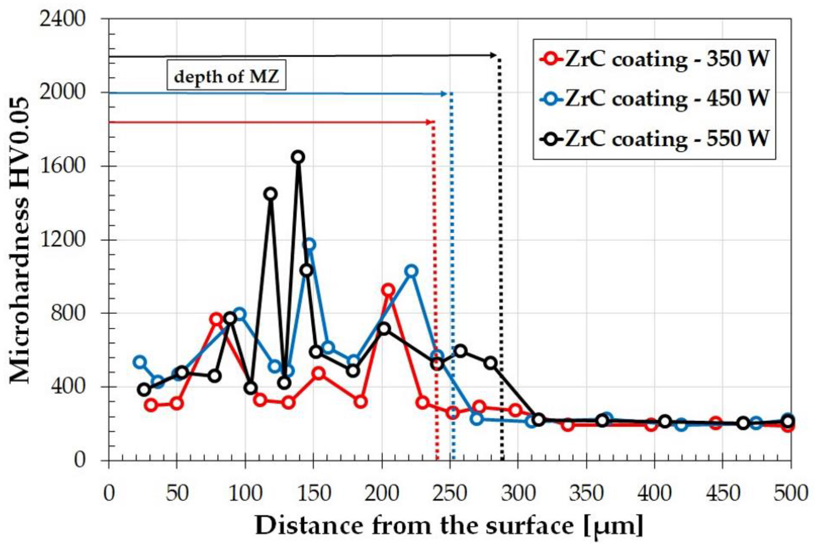
3.2.2. Microhardness of ZrC Coatings—Multiple Laser Tracks

Figure 17 shows microhardness profiles for ZrC coatings produced using different laser beam powers on the Monel® 400 alloy. The measurements were made for five consecutive laser tracks selected from the middle part of the sample. Hardness indentation tests were made in the axis of the laser tracks. The results on all five track axes were very similar. The tracks differed in the distribution of agglomerates, but the matrices were characterized by very similar hardness; Figure 17 presents sample results. The smallest microhardness value ranged from 300 HV0.05 (for laser beam power of 350 W) to about 400 HV0.05 for the remaining coatings. The matrix hardness reached a value of about 800–900 HV0.05. The use of multiple tracks resulted in an increase in hardness at higher laser beam powers. This was due to an increase in the share of carbides in the coating, including the carbides that were secondarily released in the matrix. Thus, a relationship was observed that was inverse to that of single tracks, where the substrate content increased mainly in the coating, which resulted in a decrease in hardness with laser beam power increase. Here, the same treatment resulted in an increase in ZrC content and fragmentation and mixing of agglomerates with the substrate. In addition to higher hardness of the matrix, high hardness of other agglomerates was observed. Their hardness was as high as 1800 HV0.05. Other researchers have also tried to increase Monel alloys hardness. In the paper [27], using 3D LENS printing technology (laser engineered net shaping), which is one of the varieties of laser cladding technology, a hardness in the range of 400–1200 HV was obtained. The process was carried out with Monel powders and WC as the reinforcing phase. Similarly, in the work by [24], the authors examined the properties of laser in situ cladded ZrB2-ZrC/Cu composite coatings on a copper substrate. In this case, the average microhardness value of composite coatings containing ZrC and ZrB2 was 410 HV0.2 and was almost six times higher than that of the copper substrate. However, it should be noted here that the study was on a copper substrate, not a Ni-Cu alloy.

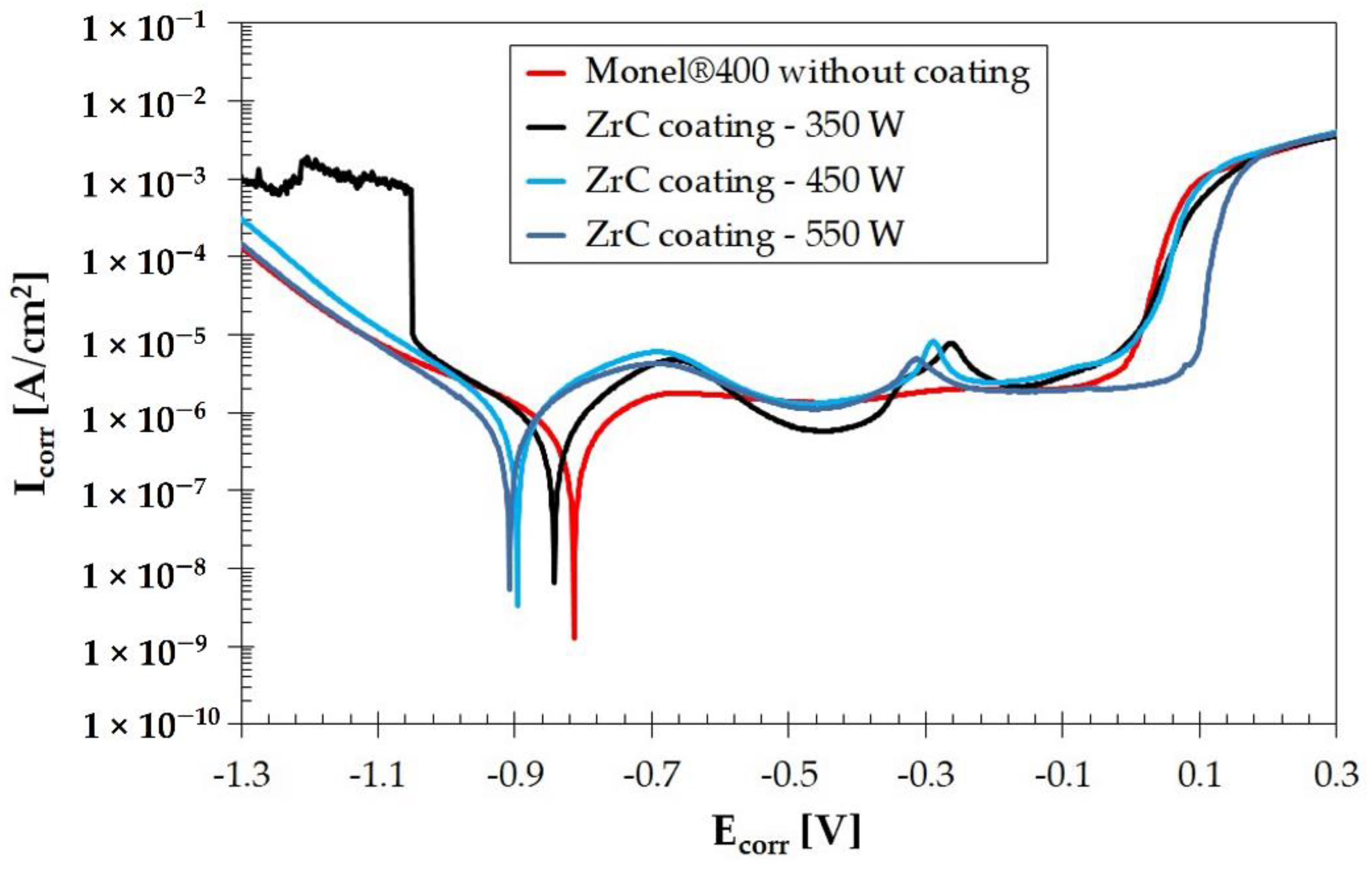
3.2.3. Corrosion Resistance of Multiple Tracks

Figure 18 shows potentiodynamic curves made for ZrC coatings produced on the Monel®400 alloy. For comparison, the graph also shows the curve corresponding to corrosion resistance of the substrate. The corrosion resistance of the Monel®400 alloy is well-known and considered to be very good. The inclusion of ZrC particles into the surface does not cause a drastic loss of these properties; however, the deterioration of corrosion resistance is visible. It was found that as the laser beam power increases, susceptibility to corrosion increases, which is probably associated with intensified mixing of ZrC particles with the Ni-Cu matrix. Weakening of the corrosion resistance is revealed by shifting the graphs to the left, i.e., towards negative potentials in relation to the substrate reference graph. In the microstructure of coatings produced at higher laser beam powers, a fairly large share of secondary ZrC was found, which could have increased susceptibility to electrochemical corrosion. The obtained corrosion parameters, i.e., corrosion potential Ecorr and corrosion current Icorr are summarized in Table 3. The effects of corrosive medium and electrical potential on coating surfaces and substrate material are presented in Figure 19a–h. It can be seen that for the Monel®400 alloy without produced coating, corrosion pits are present, but they are characterized by small sizes. These pits are quite regular and evenly distributed in the studied area (Figure 19a,b). Laser processing of ZrC pre-coat and thus the production of ZrC coating contributes to an increase in the number of corrosion pits. This may be related to a difference in electrochemical potentials between zirconium and other elements present in the substrate alloy. The normal potential of Zr is −2.36 V, Ni potential is −0.72 V, while Cu normal potential is −0.44 V. As can be seen, the differences between nickel and copper are small. Zirconium potential is more than three times smaller than that of nickel and more than five times smaller than copper. At high magnification, carbides can be observed that can be treated as corrosion microcells. For the ZrC coatings described in this paper, the uneven distribution of corrosion pits visible in the figures is related to the appearance of agglomerates, but also to coating surface unevenness, which is characteristic for coatings produced by laser processing or laser cladding. Other researchers have also conducted corrosion studies on the Monel alloy. The authors of the study [34,35] analyzed two different coatings produced on the Monel alloy in the context of corrosion. These were WC-10Ni-5Cr and WC-18Hastelloy C. The first of these coatings had a higher resistance to electrochemical corrosion, but it was still worse than the corrosion resistance of the substrate. However, these coatings caused a reduction of erosion wear. Other researchers produced graphene coatings on the Monel®400 alloy [36] by chemical vapour deposition (CVD), mainly for corrosion resistance in a marine environment. They managed to achieve the intended effect and good corrosion resistance.

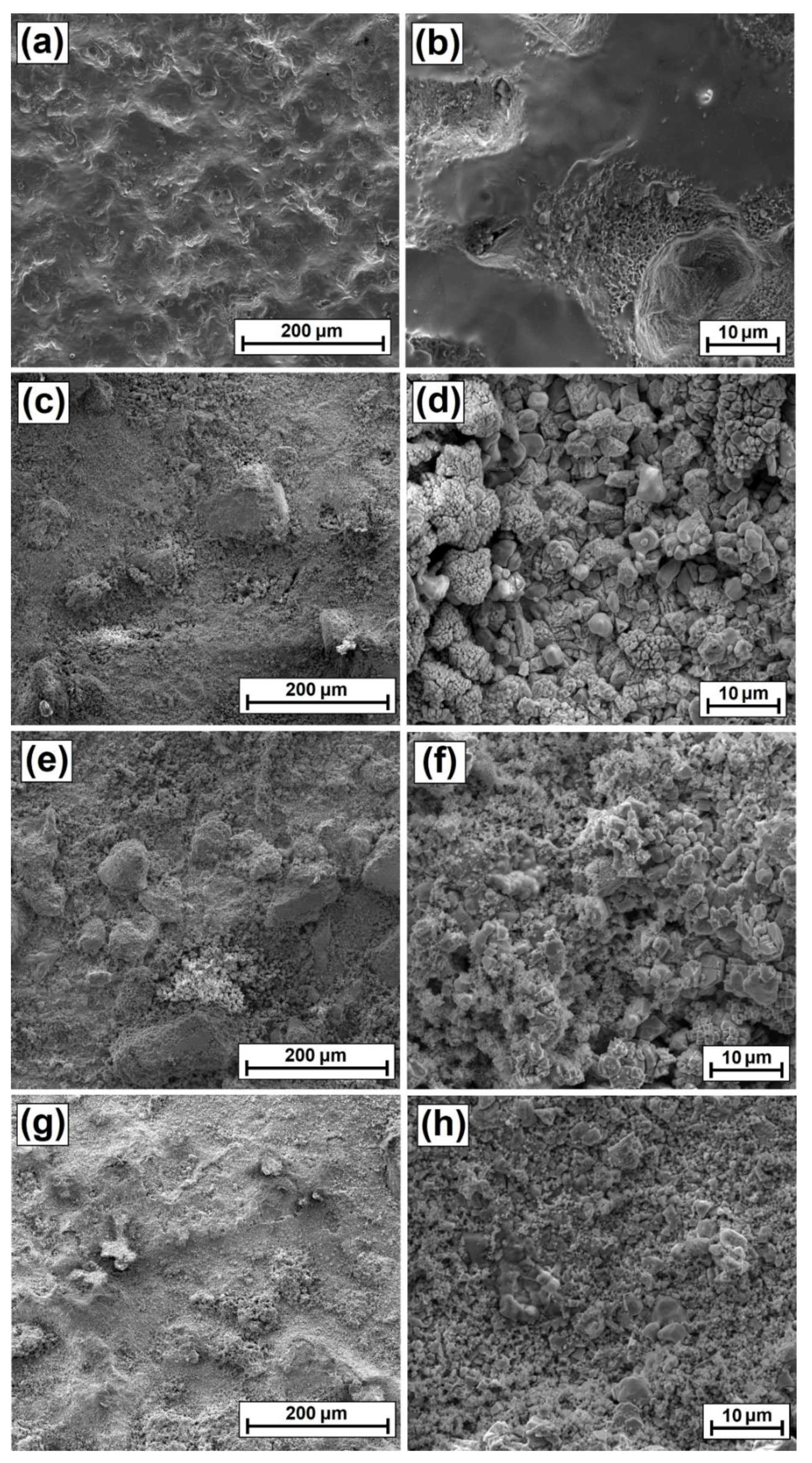
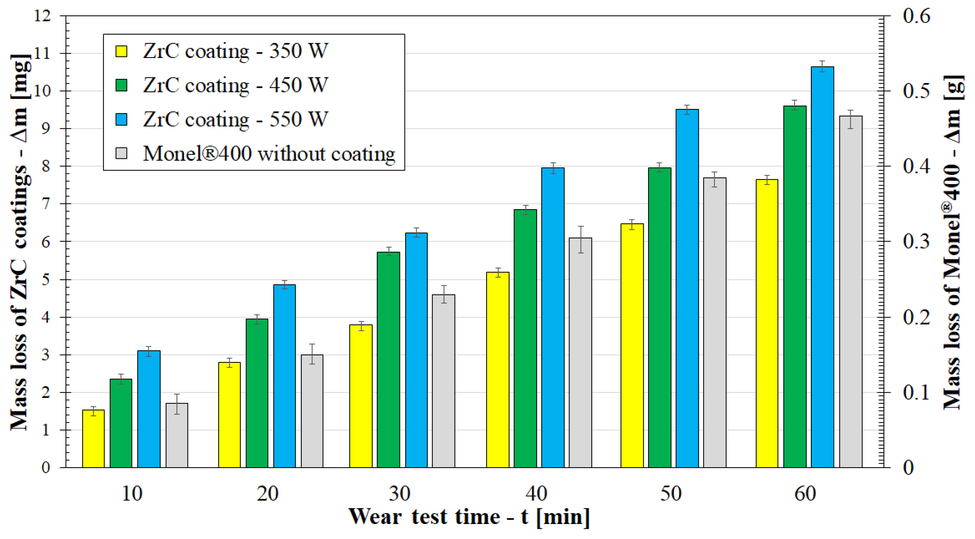
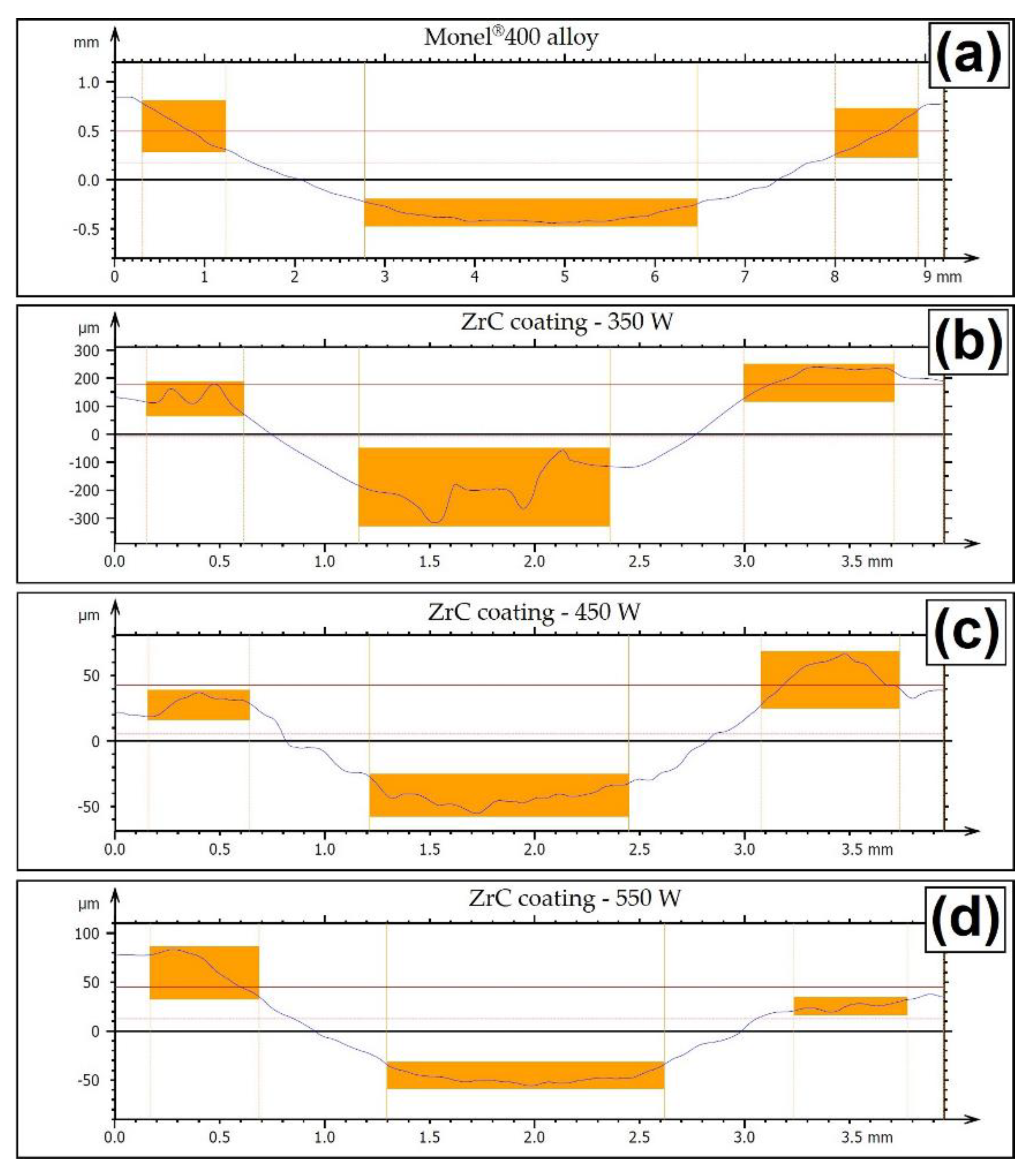
3.2.4. Wear Resistance of Multiple Tracks

Surface enrichment with reinforcing phases in the form of carbides is most often aimed at increasing hardness and durability of the substrate by creating a wear-resistant coating. This was achieved by introducing hard ZrC particles into the Monel®400alloy. Figure 20 shows the results of tests of friction wear resistance of the substrate without a produced coating and with a ZrC coating. The wear resistance of the Monel®400 alloy was very low, therefore two scales on the ordinate axes are shown. The wear resistance of each of the coatings produced is much higher than that of the substrate. The mass loss in samples with coatings could be determined in tenths of a gram, while mass loss of samples without coatings was measured in grams. Additionally, it can be concluded that there are correlations between the laser beam power used to produce multiple track coatings and wear resistance. As laser beam power increases, wear resistance of the produced coatings decreases. This is due to an increased amount of ZrC secondary carbides and the fragmentation of ZrC agglomerates by Marangoni forces in the laser remelting of each subsequent track. These changes led to a reduction in the amount of high hardness primary ZrC particles which were possibly responsible for the high wear resistance.
The results presented in the graph confirm surface SEM images after friction tests presented in Figure 21a–h. Very high flaking wear of the surface of the Monel®400 alloy can be seen. In ZrC coatings, the damage is rather marginal. The effects of scoring and microcutting are visible, which is a natural phenomenon for composite coatings, as it results from reinforcing phase particles peeling off from the matrix. Sometimes craters are also visible following agglomerate ruptures, which is why it is so important to pay special attention to their elimination in further studies on this type of composite coatings. Similar observations were made by other researchers in the surface engineering of non-ferrous alloys. In a paper [24], the authors stated that lasers cladded in-situ ZrB2-ZrC/Cu composite coatings on copper substrates not only have high microhardness in relation to the copper substrate, but that it also contributes to increasing wear resistance. Here, the wear mechanism of the composite coating was a combination of abrasive wear and adhesive wear, and wear volume loss was approximately 85% lower than that of the uncoated substrate.
Figure 22 shows sample profiles of traces obtained after wear tests for the analyzed ZrC coatings and for the Monel®400 alloy substrate. Wear resistance was much lower for samples without a coating. In the case of a coating produced with a 350 W laser beam power, an irregular profile may indicate that the carbide agglomerate ZrC was torn out of the matrix. The remaining profiles are more regular. As the laser beam power increases, the wear track width also increases. This shows that the wear resistance is reduced. The wear track width for the pure Monel®400 alloy is 3699 µm, while for the worst of the produced ZrC coating it is 1320 µm, which is almost three times smaller. For coatings produced with the laser beam power of 350 and 550 W, the differences in wear track width were not very large (within the range of 100–150 µm). It depended on the place of the surface parameters studied. Detailed results of the obtained parameters are summarized in Table 4.

4. Conclusions

On the basis of the studies conducted, the following conclusions may be formulated:
  • It is possible to produce composite ZrC coatings on a Monel®400 alloy in which the reinforcing phase is the ZrC phase and the matrix is Ni-Cu alloy.
  • Laser beam power plays a key role in shaping the coating. It is important that tests should be carried out to produce a complete coating, as for single tracks some properties differ from those obtained in the production of multiple tracks.
  • Adequately high laser beam power causes partial remelting of larger ZrC particles and the complete remelting of small ZrC particles and their precipitation in the matrix in the form of fine carbides.
  • The microhardness of laser tracks produced is closely related to the laser beam parameters used. The amount of primary and secondary carbides depends on the laser beam power applied, which affects the complete remelting or only partial remelting of the carbide surface.
  • As laser beam power increases, corrosion resistance of the coating decreases, and the production of carbide coating reduces corrosion resistance of the Monel®400 alloy. However, corrosion resistance does not decrease significantly.
  • Incorporation of ZrC particles into the surface of the Monel®400 alloy and thus forming a composite coating positively affects the wear resistance of the surface as compared to the Monel® 400 alloy without a modified surface layer.

Author Contributions

Conceptualization, D.B.; methodology, D.B., A.B., P.J. and D.P.; software, D.B. and A.B.; validation, D.B., A.B. and P.J.; investigation, D.B., A.B., P.J. and D.P.; writing—original draft preparation, D.B.; writing—review and editing, D.B. and A.B.; visualization, D.B.; supervision, D.B. All authors have read and agreed to the published version of the manuscript.

Funding

This research was funded by granted for education allocated by the Ministry of Education and Science in Poland.

Institutional Review Board Statement

Not applicable.

Informed Consent Statement

Not applicable.

Data Availability Statement

Not applicable.

Conflicts of Interest

The authors declare that they have no conflict of interest.

References

  1. Schaaf, P. Laser Processing of Materials: Fundamentals, Applications and Developments; Springer: Berlin/Heidelberg, Germany; GmbH & Co. KG: Berlin, Germany, 2010; ISBN 9783642132810. [Google Scholar]
  2. Steen, W.M.; Mazumder, J. Laser Material Processing, 4th ed.; Springer: London, UK, 2010. [Google Scholar] [CrossRef]
  3. Lawrence, J.R.; Waugh, D. Laser Surface Engineering: Processes and Applications, 1st ed.; Woodhead Publishing Series in Metals and Surface Engineering Book; Elsevier: Amsterdam, The Netherlands, 2014. [Google Scholar]
  4. Dowden, J.; Schulz, W. The Theory of Laser Materials Processing: Heat and Mass Transfer in Modern Technology, Springer Series in Materials Science, 2nd ed.; Springer: Berlin/Heidelberg, Germany, 2017; ISBN 978-3319567105. [Google Scholar]
  5. Fan, L.I.; Dong, Y.; Chen, H.; Dong, L.; Yin, Y. Wear Properties of Plasma Transferred Arc Fe-based Coatings Reinforced by Spherical WC Particles. J. Wuhan Univ. Technol.-Mat. Sci. Ed. 2019, 34, 433–439. [Google Scholar] [CrossRef]
  6. Liu, T.; Niu, Y.; Pan, X.; Shi, M.; Zheng, X.; Yu, J.; Ding, C. Laser ablation behaviors of vacuum plasma sprayed ZrC-based coatings. J. Am. Ceram. Soc. 2019, 102, 4247–4258. [Google Scholar] [CrossRef]
  7. Burakowski, T.; Wierzchon, T. Surface Engineering of Metals: Principles, Equipment, Technologies; CRC Press: Boca Raton, FL, USA, 2020; ISBN 9780367400125. [Google Scholar]
  8. Kusinski, J.; Kac, S.; Kopia, A.; Radziszewska, A.; Rozmus-Górnikowska, M.; Major, B.; Major, L.; Marczak, J.; Lisiecki, A. Laser modification of the materials surface layer–a review paper. Bull. Pol. Acad. Sci. Tech. Sci. 2012, 4, 711–728. [Google Scholar] [CrossRef]
  9. Bartkowska, A.; Bartkowski, D.; Przestacki, D.; Miklaszewski, A.; Kieruj, P. Laser processing of diffusion boronized layer produced on Monel® alloy 400—microstructure, microhardness, corrosion and wear resistance tests. Materials 2021, 14, 7529. [Google Scholar] [CrossRef] [PubMed]
  10. Kukliński, M.; Bartkowska, A.; Przestacki, D. Microstructure and selected properties of Monel 400 alloy after laser heat treatment and laser boriding using diode laser. Int. J. Adv. Manuf. Technol. 2018, 98, 3005–3017. [Google Scholar] [CrossRef] [Green Version]
  11. Bartkowski, D. Manufacturing Technology and Properties of Fe/TaC Metal Matrix Composite Coatings Produced on Medium Carbon Steel Using Laser Processing—Preliminary Study on the Single Laser Tracks. Materials 2021, 14, 5367. [Google Scholar] [CrossRef]
  12. Bartkowska, A. Characteristics of Cr-B Coatings Produced on Vanadis® 6 Tool Steel Using Laser Processing. Materials 2021, 14, 2621. [Google Scholar] [CrossRef]
  13. Dobrzański, L.A.; Labisz, K.; Piec, M.; Klimpel, A. Modelling of surface layer of the 31CrMoV12-18 tool steel using HPDL laser for alloying with TiC powder. J. Achiev. Mater. Manuf. Eng. 2007, 24, 27–34. [Google Scholar]
  14. Bartkowski, D.; Bartkowska, A.; Popielarski, P.; Hajkowski, J.; Piasecki, A. Characterization of W–Cr metal matrix composite coatings reinforced with WC particles produced on low-carbon steel using laser processing of precoat. Materials 2020, 13, 5272. [Google Scholar] [CrossRef]
  15. Bartkowska, A.; Bartkowski, D.; Piasecki, A.; Jurči, P. Influence of laser cladding parameters on microstructure, microhardness, chemical composition, wear and corrosion resistance of Fe-B composite coatings reinforced with B4C and Si particles. Coatings 2020, 10, 809. [Google Scholar] [CrossRef]
  16. Bartkowski, D.; Bartkowska, A.; Jurči, P. Laser cladding process of Fe/WC metal matrix composite coatings on low carbon steel using Yb: YAG disk laser. Opt. Laser Technol. 2021, 136, 106784. [Google Scholar] [CrossRef]
  17. Li, Z.; Yan, H.; Zhang, P.; Guo, J.; Yu, Z.; Ringsberg, J.W. Improving surface resistance to wear and corrosion of nickel-aluminum bronze by laser-clad TaC/Co-based alloy composite coatings. Surf. Coat. Technol. 2021, 405, 126592. [Google Scholar] [CrossRef]
  18. Yu, T.; Deng, Q.; Dong, G.; Yang, J. Effects of Ta on microstructure and microhardness of Ni based laser clad coating. Appl. Surf. Sci. 2011, 257, 5098–5103. [Google Scholar] [CrossRef]
  19. Bartkowski, D.; Bartkowska, A. Wear resistance in the soil of Stellite-6/WC coatings produced using laser cladding method. Int. J. Refract. Met. Hard Mater. 2017, 64, 20–26. [Google Scholar] [CrossRef]
  20. Abbas, G.; West, D.R.F. Laser surface cladding of Stellite and Stellite-SiC composite deposits for enhanced hardness and wear. Wear 1991, 143, 353–363. [Google Scholar] [CrossRef]
  21. Chao, M.-J.; Niu, X.; Yuan, B.; Liang, E.-J.; Wang, D.-S. Preparation and characterization of in situ synthesized B4C particulate reinforced nickel composite coatings by laser cladding. Surf. Coat. Technol. 2006, 201, 1102–1108. [Google Scholar] [CrossRef]
  22. Ertugrul, O.; Enrici, T.M.; Paydas, H.; Saggionetto, E.; Boschini, F.; Mertens, A. Laser cladding of TiC reinforced 316L stainless steel composites: Feedstock powder preparation and microstructural evaluation. Powder Technol. 2020, 375, 384–396. [Google Scholar] [CrossRef]
  23. Chao, M.; Wang, W.; Liang, E.; Ouyang, D. Microstructure and wear resistance of TaC reinforced Ni-based coating by laser cladding. Surf. Coat. Technol. 2008, 202, 1918–1922. [Google Scholar] [CrossRef]
  24. Lv, X.; Zhan, Z.; Cao, H.; Guo, C. Microstructure and properties of the laser cladded in-situ ZrB2-ZrC/Cu composite coatings on copper substrate. Surf. Coat. Technol. 2020, 396, 125937. [Google Scholar] [CrossRef]
  25. Bartkowski, D. Influence of Laser Beam Power on Microstructure and Microhardness of Fe/ZrC Coatings Produced on Steel Using Laser Processing—Preliminary Study on the Single Laser Tracks. Materials 2022, 15, 758. [Google Scholar] [CrossRef]
  26. Shanthos Kumar, G.; Saravanan, S.; Raghukandan, K. Effect of heat input on microstructure and mechanical properties of laser welded dissimilar grade nickel alloys. Optik 2021, 248, 168106. [Google Scholar] [CrossRef]
  27. Davoren, B.; Sacks, N.; Theron, M. Laser engineered net shaping of WC-9.2wt%Ni alloys: A feasibility study. Int. J. Refract. Met. Hard Mater. 2020, 86, 105136. [Google Scholar] [CrossRef]
  28. Davoren, B.; Sacks, N.; ·Theron, M. Microstructure characterization of WC-9.2wt%Monel 400 fabricated using laser engineered net shaping. Prog. Addit. Manuf. 2021, 6, 431–443. [Google Scholar] [CrossRef]
  29. Rai, A.K.; Srinivasulu, B.; Paula, C.P.; Singhd, R.; Rai, R.K.; Mishra, G.K.; Bontha, S.; Bindra, K.S. Development of thick SiC coating on thin wall tube of zircaloy-4 using laser based directed energy deposition technique. Surf. Coat. Technol. 2020, 398, 126088. [Google Scholar] [CrossRef]
  30. Wang, Q.; Shi, J.; Zhang, L.; Xiong, J.; Li, J.; Ma, N.; Feng, J. Additive manufacturing of a high-strength ZrC-SiC and TC4 gradient structure based on a combination of laser deposition technique and brazing. J. Mater. 2021, 7, 766–779. [Google Scholar] [CrossRef]
  31. Rajesh Kannan, A.; Mohan Kumar, S.; Pramod, R.; Siva Shanmugam, N.; Vishnukumar, M. Channabasavanna Microstructure and corrosion resistance of Ni-Cu alloy fabricated through wire arc additive manufacturing. Mater. Lett. 2022, 308, 131262. [Google Scholar] [CrossRef]
  32. Harrison, R.W.; Lee, W.E. Processing and properties of ZrC, ZrN and ZrCN ceramics: A review. Adv. Appl. Ceram. 2016, 5, 294–307. [Google Scholar] [CrossRef] [Green Version]
  33. King, D.; Middendorf, J.; Cissel, K.; Key, T.; Carney, C. Selective laser melting for the preparation of an ultra-high temperaturę ceramic coating. Ceram. Int. 2019, 45, 2466–2473. [Google Scholar] [CrossRef]
  34. Singh, N.K.; Kumar, A.; Ang, A.S.M.; Mahajan, D.K.; Singh, H. Characterization and Slurry Erosion Mechanisms of Nickel-Based Cermet Coatings on Monel K-500. J. Therm. Spray Technol. 2021, 30, 2138–2154. [Google Scholar] [CrossRef]
  35. Singh, N.K.; Vinay, G.; Ang, A.S.M.; Mahajan, D.K.; Singh, H. Cavitation erosion mechanisms of HVOF-sprayed Ni-based cermet coatings in 3.5% NaCl environment. Surf. Coat. Technol. 2022, 434, 128194. [Google Scholar] [CrossRef]
  36. Al-Saadi, S.; Singh Raman, R.K.; Anisur, M.R.; Ahmed, S.; Crosswell, S.; Alnuwaiser, M.; Panter, C. Graphene coating on a nickel-copper alloy (Monel 400) for microbial corrosion resistance: Electrochemical and surface characterizations. Corros. Sci. 2021, 182, 109299. [Google Scholar] [CrossRef]
Figure 1. Morphology and size of ZrC powder.
Coatings 12 00651 g001
Figure 2. ZrC pre-coat in the form of paste applied on the Monel®400 substrate.
Coatings 12 00651 g002
Figure 3. Scheme of Ni-Cu/ZrC coating production using laser processing. (a) single laser tracks; (b) multiple laser track.
Coatings 12 00651 g003
Figure 10. Chemical composition (EDS mapping) of single laser tracks after laser processing using laser beam power: (a) 350 W, (b) 450 W, (c) 550 W.
Coatings 12 00651 g010
Figure 11. Chemical composition (EDS mapping) of remelted zone of ZrC coatings produced using laser beam power: (a) 350 W, (b) 450 W, (c) 550 W.
Coatings 12 00651 g011
Figure 12. Microhardness of ZrC coatings produced using laser beam power of 350 W, 450 W and 550 W.
Coatings 12 00651 g012
Figure 13. Vickers microhardness indentations in the remelted zone of single laser tracks produced using a laser beam power of 550 W.
Coatings 12 00651 g013
Figure 14. Microstructure of ZrC coating produced on the Monel®400 alloy produced using laser beam power 350 W—multiple laser tracks: (a) view of the entire remelted zone, (b) enlarged image of the entire remelted zone SE, (c) enlarged image of the entire remelted zone BSE, (d) enlargement of the middle zone, (e) sub substrate zone, (f) enlargement of sub substrate zone.
Coatings 12 00651 g014
Figure 15. Microstructure of ZrC coating produced on Monel®400 alloy produced using laser beam power 450 W—multiple laser tracks: (a) view of the entire remelted zone, (b) enlarged image of the entire remelted zone, (c) middle zone (d) enlargement of the middle zone, (e) sub substrate zone, (f) enlargement of the sub substrate zone.
Coatings 12 00651 g015
Figure 16. Microstructure of ZrC coating produced on the Monel®400 alloy using a laser beam power of 550 W—multiple laser tracks: (a) view of the entire remelted zone, (b) enlarged image of the entire remelted zone, (c) middle zone, (d) enlargement of the middle zone, (e) sub substrate zone, (f) enlargement of sub substrate zone.
Coatings 12 00651 g016
Figure 17. Microhardness of ZrC coatings (multiple laser tracks) produced using laser beam powers of 350, 450 and 550 W.
Coatings 12 00651 g017
Figure 18. Corrosion resistance curve for ZrC coatings (multiple laser tracks) produced using laser beam power of 350, 450 and 550 W and for the substrate material.
Coatings 12 00651 g018
Figure 19. Surface condition after corrosion test of the Monel®400 alloy (a,b) and ZrC coating produced on Monel®400 alloy produced using laser beam power: 350 W (c,d), 450 W (e,f), 550 W (g,h).
Coatings 12 00651 g019
Figure 20. Wear resistance results of Monel®400 alloy and ZrC coating produced on the Monel®400 alloy produced using laser beam powers of 350, 450, and 550 W.
Coatings 12 00651 g020
Figure 21. Surface condition after wear resistance test of the Monel®400 alloy (a,b) and ZrC coating produced on the Monel®400 alloy produced using laser beam power: 350 W (c,d), 450 W (e,f), 550 W (g,h).
Coatings 12 00651 g021
Figure 22. 3D Surface parameters obtained after wear resistance tests of the Monel®400 alloy (a) and ZrC coating produced on the Monel®400 alloy produced using laser beam power: 350 W (b), 450 W (c), 550 W (d).
Coatings 12 00651 g022
Table 1. Chemical composition of Monel®400 used [wt.%].
CuFe MnSiCSNi
322.31.80.30.20.18bal.
Table 2. Chemical composition (EDS analysis) of the areas marked with a squares in Figure 5, Figure 7 and Figure 9.
Coating Type/Test ZoneNoZrCCuNi
Monel®400/ZrC
350 W
Middle zone
(Figure 5a)
140.313.614.931.2
279.316.30.14.3
321.88.223.246.8
48.96.423.361.4
582.314.70.12.9
Monel®400/ZrC
350 W
Matrix of sub substrate zone
(Figure 5b)
13.57.826.262.6
23.68.422.965.1
32.37.626.064.1
40.96.725.666.8
53.58.226.062.3
Monel®400/ZrC
350 W
ZrC agglomerate in sub substrate zone
(Figure 5c)
119.78.120.751.6
245.611.411.431.6
341.010.713.434.9
480.916.80.22.1
581.615.70.12.6
Monel®400/ZrC
450 W
Subsurface zone
(Figure 7a)
174.513.62.89.1
28.76.526.858.0
36.06.822.664.6
473.914.12.59.5
57.05.825.761.5
Monel®400/ZrC
450 W
Middle zone
(Figure 7b)
141.611.115.232.1
24.36.029.859.8
38.86.822.561.9
421.09.322.946.8
55.36.629.858.3
Monel®400/ZrC
450 W
Subsubstrate zone
(Figure 7c)
160.711.95.921.5
224.39.120.146.6
35.75.328.560.5
48.86.427.257.6
533.212.217.337.3
Monel®400/ZrC
550 W
Subsurface zone
(Figure 9a)
17.45.024.663.0
226.811.221.640.4
328.810.519.641.1
412.96.422.658.1
59.26.526.557.8
Monel®400/ZrC
550 W
Middle zone
(Figure 9b)
111.64.821.662.0
226.511.218.443.9
315.65.220.259.0
423.910.723.541.9
57.35.126.461.2
Monel®400/ZrC
550 W
Subsubstrate zone
(Figure 9c)
118.37.923.250.6
243.610.415.830.2
344.810.113.731.4
419.28.121.151.6
518.77.822.351.2
Table 3. Corrosion resistance parameters for ZrC coatings (multiple laser tracks) produced using laser beam powers of 350, 450 and 550 W and for the substrate material.
ParametersIcorr
[A/cm2]
Ecorr
[V]
Monel®400
without coating
2.91 × 10⁻⁷−8.14 × 10⁻¹
ZrC coating
350 W
3.19 × 10⁻⁷−8.42 × 10⁻¹
ZrC coating
450 W
5.23 × 10⁻⁷−8.97 × 10⁻¹
ZrC coating
550 W
3.19 × 10⁻⁷−9.08 × 10⁻¹
Table 4. Surface roughness parameters for selected profiles obtained during tests (µm).
ParametersWithout Coating ZrC Coating
350 W
ZrC Coating
450 W
ZrC Coating
550 W
Ra5.39516.752.4621.981
Rz23.0089.669.9457.444
Sa307.3115.560.0045.01
Sq707.9288.4222.7227.7
Sz1507659.5432.5349.0
wear track width3699119712351320
max. wear track depth938.4497.898.34100.7
average wear track depth870.2370.086.1293.14
Publisher’s Note: MDPI stays neutral with regard to jurisdictional claims in published maps and institutional affiliations.

