
Health and Durability of Protective and Thermal Barrier Coatings Monitored in Service by Visual Inspection


Abstract
:1. Introduction
2. Materials and Methods
2.1. Engine
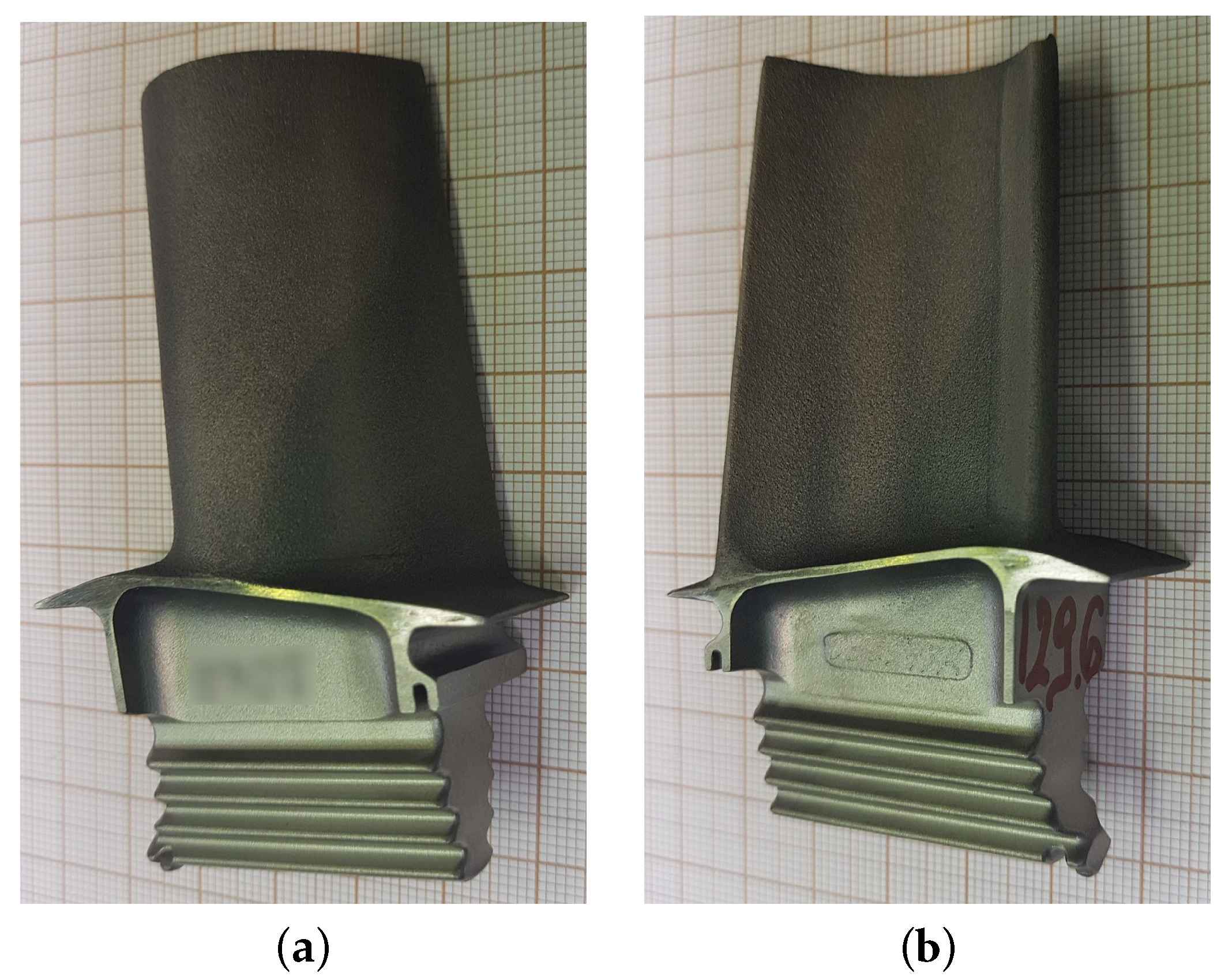
2.2. HPT Blade
2.3. Coatings
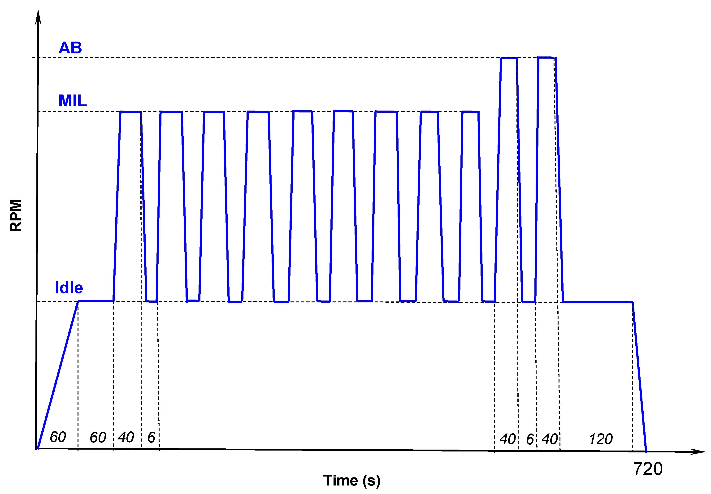
2.4. Engine Testing
2.5. Inspection
3. Results
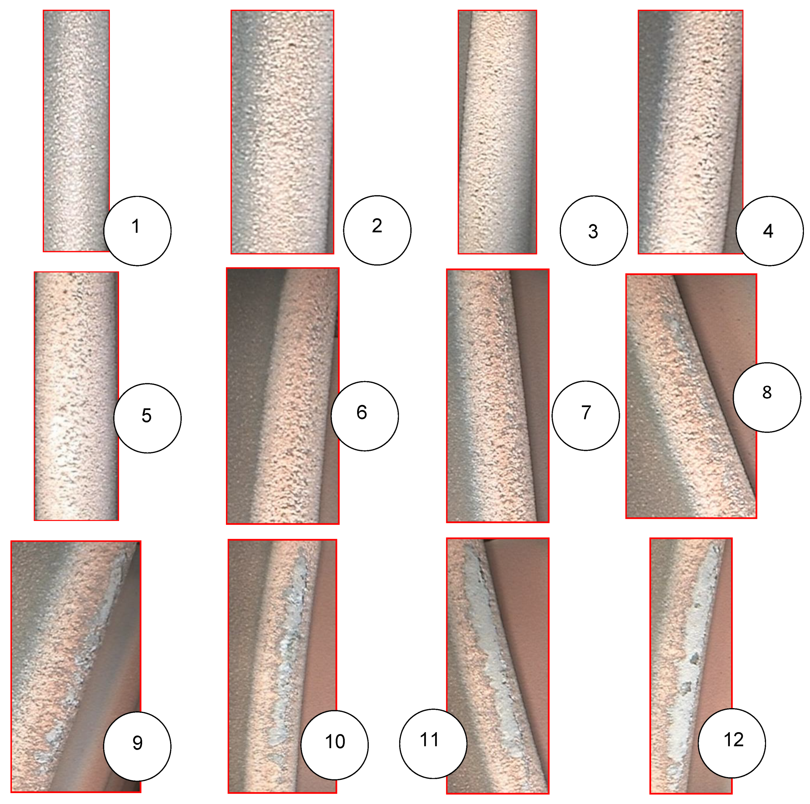
3.1. CVD
3.2. APS + VPA
3.3. APS
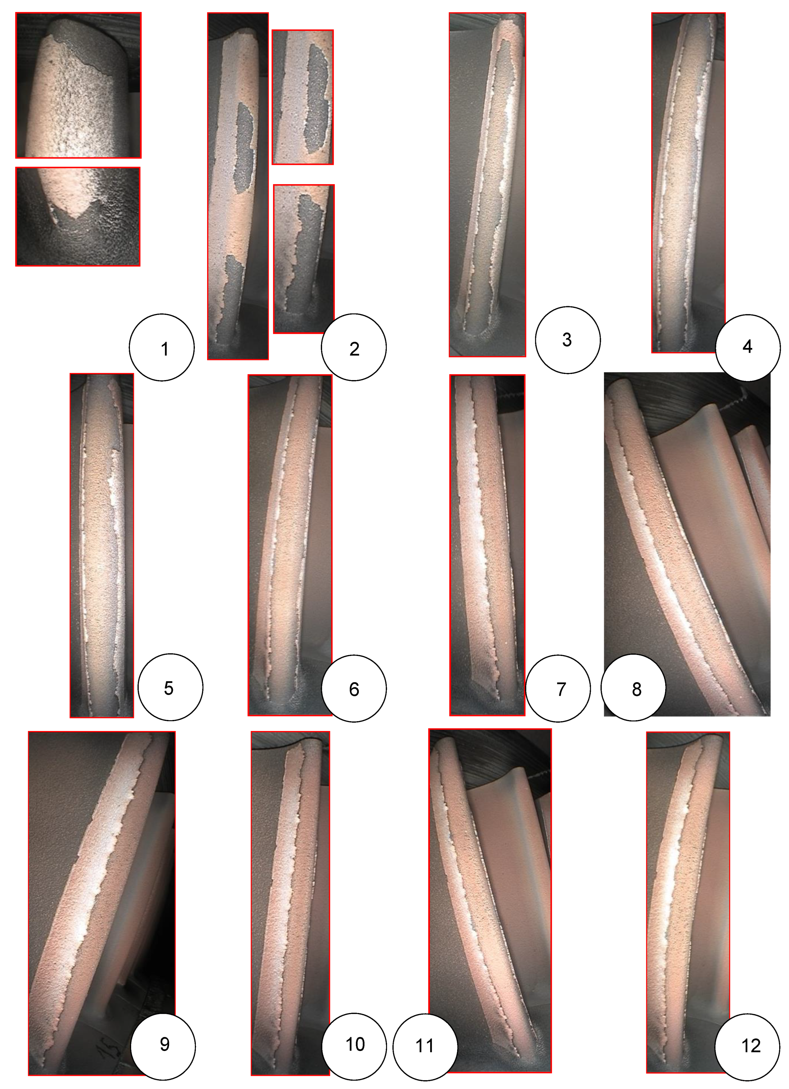
3.4. APS + SLURRY
3.5. APS + TBC
4. Discussion
5. Conclusions
- Despite its limitations, borescope inspection is one of the few tools available for the in-service monitoring of blade coatings.
- The observed pace and mechanism of degradation were specific to the type of coating.
- APS is a cost-effective technology that can replace PVD methods on turbine blades when the proper coating structure and adhesion are ensured.
- The presence of damage at this stage of development is not a problem, and it absolutely does not exclude any of the tested processes.
Author Contributions
Funding
Institutional Review Board Statement
Informed Consent Statement
Data Availability Statement
Conflicts of Interest
Abbreviations
| AB | Afterburner |
| AMT | Accelerated mission test |
| APS | Atmospheric plasma spraying |
| CCD | Charge-coupled device |
| CVD | Chemical Vapor Deposition |
| CT | Computed tomography |
| EB-PVD | Electron Beam Physical Vapor Deposition |
| FH | Flight hours |
| HPT | High pressure turbine |
| ITWL | The Air Force Institute of Technology in Warsaw |
| MIL | Military power |
| LE | Leading edge |
| LED | Light-emitting diode |
| LPT | Low pressure turbine |
| PVD | Physical Vapor Deposition |
| SEM | Scanning Electron Microscopy |
| TBC | Thermal Barrier Coating |
| TBO | Time between overhauls |
| TGO | Thermally grown oxides |
| TE | Trailing edge |
| VPA | Vapor phase aluminide |
References
- Ozgurluk, Y.; Doleker, K.M.; Ozkan, D.; Ahlatci, H.; Karaoglanli, A.C. Cyclic hot corrosion failure behaviors of EB-PVD TBC systems in the presence of sulfate and vanadate molten salts. Coatings 2019, 9, 166. [Google Scholar] [CrossRef] [Green Version]
- Song, D.; Song, T.; Paik, U.; Lyu, G.; Jung, Y.G.; Choi, B.G.; Kim, I.S.; Zhang, J. Crack-growth behavior in thermal barrier coatings with cyclic thermal exposure. Coatings 2019, 9, 365. [Google Scholar] [CrossRef] [Green Version]
- Kopec, M.; Kukla, D.; Yuan, X.; Rejmer, W.; Kowalewski, Z.L.; Senderowski, C. Aluminide Thermal Barrier Coating for High Temperature Performance of MAR 247 Nickel Based Superalloy. Coatings 2021, 11, 48. [Google Scholar] [CrossRef]
- Goral, M.; Pytel, M.; Ochal, K.; Drajewicz, M.; Kubaszek, T.; Simka, W.; Nieuzyla, L. Microstructure of aluminide coatings modified by Pt, Pd, Zr and Hf formed in low-activity CVD process. Coatings 2021, 11, 421. [Google Scholar] [CrossRef]
- Kościelniak, B.; Chmiela, B.; Sozańska, M.; Swadźba, R.; Drajewicz, M. Oxidation Behavior of Inconel 740H Nickel Superalloy in Steam Atmosphere at 750 °C. Materials 2021, 14, 4536. [Google Scholar] [CrossRef]
- Tamarin, Y. Protective Coatings for Turbine Blades; ASM International: Materials Park, OH, USA, 2002; p. 247. [Google Scholar]
- Mishra, R.K.; Kumar, P.; Muduli, S.K. Failure Prevention of Gas Turbine Blades Through Pack Aluminization. J. Fail. Anal. Prev. 2018, 18, 1120–1126. [Google Scholar] [CrossRef]
- Maricocchi, A.; Bartz, A.; Wortman, D. PVD TBC experience on GE aircraft engines. J. Therm. Spray Technol. 1997, 6, 193–198. [Google Scholar] [CrossRef] [Green Version]
- Swadźba, R.; Wiedermann, J.; Hetmańczyk, M.; Swadźba, L.; Mendala, B.; Witala, B.; Komendera, Ł. Microstructure degradation of EB-PVD TBCs on Pd-Pt-modified aluminide coatings under cyclic oxidation conditions. Surf. Coat. Technol. 2013, 237, 16–22. [Google Scholar] [CrossRef]
- Ebach-Stahl, A.; Schulz, U.; Swadźba, R.; Munawar, A.U. Lifetime improvement of EB-PVD 7YSZ TBCs by doping of Hf or Zr in NiCoCrAlY bond coats. Corros. Sci. 2021, 181, 109205. [Google Scholar] [CrossRef]
- Guo, D.; Wang, Y.; Fernandez, R.; Zhao, L.; Jodoin, B. Cold spray for production of in-situ nanocrystalline MCrAlY coatings – Part I: Process analysis and microstructure characterization. Surf. Coat. Technol. 2021, 409, 126854. [Google Scholar] [CrossRef]
- Li, X.; Peng, X.Y.; Dong, H.; Zhou, Y.; Wang, T.; Ren, K.; Sun, L. The Evaluation of Durability of Plasma-Sprayed Thermal Barrier Coatings with Double-layer Bond Coat. Coatings 2019, 9, 241. [Google Scholar] [CrossRef] [Green Version]
- Nicolaus, M.; Möhwald, K.; Maier, H.J. Thermally Sprayed Nickel-Based Repair Coatings for High-Pressure Turbine Blades: Controlling Void Formation during a Combined Brazing and Aluminizing Process. Coatings 2021, 11, 725. [Google Scholar] [CrossRef]
- Liebert, C.H.; Levine, S.R. Further Industrial Tests of Ceramic Thermal-Barrier Coatings; NASA Technical Paper 2057; NASA Lewis Research Center: Cleveland, OH, USA, 1982. [Google Scholar]
- Savinkin, V.V.; Vizureanu, P.; Sandu, A.V.; Ratushnaya, T.Y.; Ivanischev, A.A.; Surleva, A. Improvement of the turbine blade surface phase structure recovered by plasma spraying. Coatings 2020, 10, 62. [Google Scholar] [CrossRef] [Green Version]
- Ghadami, F.; Davoudabadi, M.A.; Ghadami, S. Cyclic Oxidation Properties of the Nanocrystalline AlCrFeCoNi High-Entropy Alloy Coatings Applied by the Atmospheric Plasma Spraying Technique. Coatings 2022, 12, 372. [Google Scholar] [CrossRef]
- Yun, J.; Kim, Y.; Lee, J.M.; Song, H.; Wee, S.; Koo, J.M.; Lee, Y.Z.; Seok, C.S. The Study on Delamination Life of TBC through Burner-Rig Test. Int. J. Precis. Eng. Manuf. 2017, 18, 555–560. [Google Scholar] [CrossRef]
- Shahoo, P.; Sobieski, P.A. Performance Characteristics of Thermal Barrier Coatings: A Case Study. In Proceedings of the ASME Turbo Expo 2007: Power for Land, Sea and Air, Montreal, QC, Canada, 14–17 May 2007; Volume 5, pp. 191–197. [Google Scholar] [CrossRef]
- Witz, G.; Schaudinn, M.; Sopka, J.; Buecklers, T. Development of Advanced Thermal Barrier Coatings with Improved Temperature Capability. In Proceedings of the ASME Turbo Expo 2016: Turbomachinery Technical Conference and Exposition, Seoul, Korea, 13–17 June 2016; pp. 1–8. [Google Scholar] [CrossRef]
- Ghadami, F.; Sabour Rouh Aghdam, A.; Ghadami, S. Microstructural characteristics and oxidation behavior of the modified MCrAlX coatings: A critical review. Vacuum 2021, 185, 109980. [Google Scholar] [CrossRef]
- Hu, Z.C.; Liu, B.; Wang, L.; Cui, Y.H.; Wang, Y.W.; Ma, Y.D.; Sun, W.W.; Yang, Y. Research Progress of Failure Mechanism of Thermal Barrier Coatings at High Temperature via Finite Element Method. Coatings 2020, 10, 732. [Google Scholar] [CrossRef]
- Chang, S.; Oh, K.Y. Contribution of High Mechanical Fatigue to Gas Turbine Blade Lifetime during Steady-State Operation. Coatings 2019, 9, 229. [Google Scholar] [CrossRef] [Green Version]
- Wei, Z.Y.; Cai, H.N. Understanding the Failure Mechanism of Thermal Barrier Coatings Considering the Local Bulge at the Interface between YSZ Ceramic and Bond Layer. Materials 2021, 15, 275. [Google Scholar] [CrossRef]
- Kumar, S.; Kant, S.; Suri, N.M.; Verma, R. Effects of Thermal Barrier Coatings on Diesel and Gas turbine engines: A review. Int. Res. J. Eng. Technol. 2016, 3, 134–139. [Google Scholar]
- Abdul-Aziz, A.; Wroblewski, A. Durability Analysis and Experimental Validation of Environmental Barrier Coating (EBC) Performance Using Combined Digital Image Correlation and NDE. Coatings 2016, 6, 70. [Google Scholar] [CrossRef] [Green Version]
- Mevissen, F.; Meo, M. A Review of NDT/Structural Health Monitoring Techniques for Hot Gas Components in Gas Turbines. Sensors 2019, 19, 711. [Google Scholar] [CrossRef] [PubMed] [Green Version]
- Moskal, G.; Swadźba, R.; Witala, B. Non-Destructive Measurement of Top Coat Thickness in TBC Systems by 3D Optical Topometry. Nondestruct. Test. Eval. 2015, 30, 39–48. [Google Scholar] [CrossRef]
- Aschenbruck, J.; Adamczuk, R.; Seume, J.R. Recent Progress in Turbine Blade and Compressor Blisk Regeneration. Procedia CIRP 2014, 22, 256–262. [Google Scholar] [CrossRef] [Green Version]
- Kukla, D.; Kopec, M.; Sitek, R.; Olejnik, A.; Kachel, S.; Kiszkowiak, Ł. A Novel Method for High Temperature Fatigue Testing of Nickel Superalloy Turbine Blades with Additional NDT Diagnostics. Materials 2021, 14, 1392. [Google Scholar] [CrossRef]
- Bruchwald, O.; Nicolaus, M.; Frackowiak, W.; Reimche, W.; Möhwald, K.; Maier, H.J. Material characterization of thin coatings using high frequency eddy current technology. In Proceedings of the 19th World Conference on Non-Destructive Testing (WCNDT 2016), Munich, Germany, 13–17 June 2016; pp. 1–6. [Google Scholar]
- Chen, H.L.R.; Zhang, B.; Alvin, M.A.; Lin, Y. Ultrasonic Detection of Delamination and Material Characterization of Thermal Barrier Coatings. J. Therm. Spray Technol. 2012, 21, 1184–1194. [Google Scholar] [CrossRef]
- Zhang, S.; Lv, G.; Guo, S.; Zhang, Y.; Feng, W. Porosity Characterization of Thermal Barrier Coatings by Ultrasound with Genetic Algorithm Backpropagation Neural Network. Complexity 2021, 2021, 8869928. [Google Scholar] [CrossRef]
- Hastie, S.; Chan, A.; Wiens, K.; Nagy, D.; Tollett, R.; Lowden, P. Computed Tomography Wall Thickness Inspection to Support Gas Turbine Blade Life Extension. In Proceedings of the ASME Turbo Expo 2021: Turbomachinery Technical Conference and Exposition, Virtual, 7–11 June 2021; American Society of Mechanical Engineers: Huston, TX, USA, 2021. [Google Scholar] [CrossRef]
- Przysowa, R.; Chalimoniuk, M.; Grzelka-Gajek, D.; Shakalo, R.; Karpenko, A. CT Inspection of Cooled Turbine Blades. J. KONBiN 2020, 50, 307–331. [Google Scholar] [CrossRef]
- Zhao, Y.; Shinmi, A.; Zhao, X.; Withers, P.J.; Van Boxel, S.; Markocsan, N.; Nylen, P.; Xiao, P. Investigation of Interfacial Properties of Atmospheric Plasma Sprayed Thermal Barrier Coatings with Four-Point Bending and Computed Tomography Technique. Surf. Coat. Technol. 2012, 206, 4922–4929. [Google Scholar] [CrossRef]
- Błachnio, J.; Chalimoniuk, M.; Kułaszka, A.; Borowczyk, H.; Zasada, D. Exemplification of Detecting Gas Turbine Blade Structure Defects Using the X-ray Computed Tomography Method. Aerospace 2021, 8, 119. [Google Scholar] [CrossRef]
- Panas, A.J.; Senderowski, C.; Fikus, B. Thermophysical properties of multiphase Fe-Al intermetallic-oxide ceramic coatings deposited by gas detonation spraying. Thermochim. Acta 2019, 676, 164–171. [Google Scholar] [CrossRef]
- Curry, N.; VanEvery, K.; Snyder, T.; Markocsan, N. Thermal conductivity analysis and lifetime testing of suspension plasma-sprayed thermal barrier coatings. Coatings 2014, 4, 630–650. [Google Scholar] [CrossRef]
- Ptaszek, G.; Cawley, P.; Almond, D.; Pickering, S. Artificial Disbonds for Calibration of Transient Thermography Inspection of Thermal Barrier Coating Systems. NDT E Int. 2012, 45, 71–78. [Google Scholar] [CrossRef]
- Kidd, G.; Nunn, J. Application of Pulsed Thermography to Quality Assurance of Thermal Barrier Coatings. Proc. Inst. Mech. Eng. Part G J. Aerosp. Eng. 2012, 226, 873–880. [Google Scholar] [CrossRef]
- Chung, Y.; Lee, S.; Kim, W. Latest Advances in Common Signal Processing of Pulsed Thermography for Enhanced Detectability: A Review. Appl. Sci. 2021, 11, 12168. [Google Scholar] [CrossRef]
- Bogdan, M.; Błachnio, J.; Spychała, J.; Zasada, D. Assessment of usability of the exploited gas turbine blade heat-resistant coatings. Eng. Fail. Anal. 2019, 105, 337–346. [Google Scholar] [CrossRef]
- Wang, Y.; Gao, X.; Netzelmann, U. Detection of Surface Cracks in Metals under Coatings by Induction Thermography. In Proceedings of the 2018 International Conference on Quantitative InfraRed Thermography, QIRT Council, Berlin, Germany, 25–29 June 2018; pp. 602–611. [Google Scholar] [CrossRef]
- Liu, Z.; Jiao, D.; Shi, W.; Xie, H. Linear Laser Fast Scanning Thermography NDT for Artificial Disbond Defects in Thermal Barrier Coatings. Opt. Express 2017, 25, 31789. [Google Scholar] [CrossRef]
- Muzika, L.; Svantner, M.; Honner, M.; Houdkova, S. Laser Scanning Thermography for Coating Thickness Inspection. Eng. Proc. 2021, 8, 17. [Google Scholar] [CrossRef]
- Fukuchi, T.; Ozeki, T.; Okada, M.; Fujii, T. Nondestructive Inspection of Thermal Barrier Coating of Gas Turbine High Temperature Components. IEEJ Trans. Electr. Electron. Eng. 2016, 11, 391–400. [Google Scholar] [CrossRef]
- Isern, L.; Waddie, A.J.; Chalk, C.; Moore, A.J.; Nicholls, J.R. Non-Destructive Thickness Measurement of Thermal Barrier Coatings Using Terahertz Radiation. Emergent Mater. 2021, 4, 1547–1557. [Google Scholar] [CrossRef]
- Unnikrishnakurup, S.; Dash, J.; Ray, S.; Pesala, B.; Balasubramaniam, K. Nondestructive Evaluation of Thermal Barrier Coating Thickness Degradation Using Pulsed IR Thermography and THz-TDS Measurements: A Comparative Study. NDT E Int. 2020, 116, 102367. [Google Scholar] [CrossRef]
- Marinetti, S.; Robba, D.; Cernuschi, F.; Bison, P.G.; Grinzato, E. Thermographic Inspection of TBC Coated Gas Turbine Blades: Discrimination between Coating over-Thicknesses and Adhesion Defects. Infrared Phys. Technol. 2007, 49, 281–285. [Google Scholar] [CrossRef]
- Frackowiak, W.; Barton, S.; Reimche, W.; Bruchwald, O.; Zaremba, D.; Schlobohm, J.; Li, Y.; Kaestner, M.; Reithmeier, E. Near-Wing Multi-Sensor Diagnostics of Jet Engine Components. In Proceedings of the ASME Turbo Expo 2018: Turbomachinery Technical Conference and Exposition, Oslo, Norway, 11–15 June 2018; American Society of Mechanical Engineers: Huston, TX, USA, 2018; pp. 1–8. [Google Scholar] [CrossRef]
- Schlobohm, J.; Bruchwald, O.; Fra̧ckowiak, W.; Li, Y.; Kästner, M.; Pösch, A.; Reimche, W.; Maier, H.J.; Reithmeier, E. Advanced Characterization Techniques for Turbine Blade Wear and Damage. Procedia CIRP 2017, 59, 83–88. [Google Scholar] [CrossRef]
- Yang, D.; Pankov, V.; Zhao, L.; Patnaik, P. Laser deposited high temperature thin film sensors for gas turbines. Aircr. Eng. Aerosp. Technol. 2020, 92, 2–7. [Google Scholar] [CrossRef]
- Feist, J. Luminescent Thermal History Sensors Fundamentals and Applications for Thermal Profiling. In Proceedings of the STO-MP-AVT-229—Test Cell and Controls Instrumentation and EHM Technologies for Military Air, Land and Sea Turbine Engines, NATO STO, Rzeszów, Poland, 20–23 April 2015; pp. 1–15. [Google Scholar]
- Jenkins, T.P.; Hess, C.F.; Allison, S.W.; Eldridge, J.I. Measurements of turbine blade temperature in an operating aero engine using thermographic phosphors. Meas. Sci. Technol. 2020, 31, 044003. [Google Scholar] [CrossRef]
- Aust, J.; Pons, D.; Mitrovic, A. Evaluation of Influence Factors on the Visual Inspection Performance of Aircraft Engine Blades. Aerospace 2022, 9, 18. [Google Scholar] [CrossRef]
- Szczepankowski, A.; Przysowa, R. Thermal degradation of turbine components in a military turbofan. Eng. Fail. Anal. 2022, 134, 106088. [Google Scholar] [CrossRef]
- Bogdan, M.; Błachnio, J.; Kułaszka, A.; Zasada, D. Investigation of the Relationship between Degradation of the Coating of Gas Turbine Blades and Its Surface Color. Materials 2021, 14, 7843. [Google Scholar] [CrossRef]
- Kozakiewicz, A.; Jóźwiak, S.; Jóźwiak, P.; Kachel, S. Material Origins of the Accelerated Operational Wear of RD-33 Engine Blades. Materials 2021, 14, 336. [Google Scholar] [CrossRef]
- Kablov, E.; Muboyadzhyan, S.; Budinovskii, S.; Lutsenko, A. Ion-plasma protective coatings for gas-turbine engine blades. Russ. Metall. 2007, 2007, 364–372. [Google Scholar] [CrossRef]
- Yakovchuk, K.Y.; Rudoi, Y.É.; Onoprienko, E.V.; Malysheva, V.G. Effect of Protective Coatings on Mechanical Properties of ZhS32-VI Heat-Resistant Alloy. Strength Mater. 2010, 42, 352–361. [Google Scholar] [CrossRef]
- Swadzba, L.; Maciejny, A.; Mendala, B. Overaluminising of NiCoCrAlY Coatings by Arc PVD on Ni-Base Superalloys. In Proceedings of the Superalloys 2000 (Ninth International Symposium), Champion, PA, USA, 17–21 September 2000; pp. 693–701. [Google Scholar] [CrossRef]
- Guo, X.; Zheng, W.; Xiao, C.; Li, L.; Antonov, S.; Zheng, Y.; Feng, Q. Evaluation of microstructural degradation in a failed gas turbine blade due to overheating. Eng. Fail. Anal. 2019, 103, 308–318. [Google Scholar] [CrossRef]
- Wee, S.; Do, J.; Kim, K.; Lee, C.; Seok, C.; Choi, B.G.; Choi, Y.; Kim, W. Review on mechanical thermal properties of superalloys and thermal barrier coating used in gas turbines. Appl. Sci. 2020, 10, 5476. [Google Scholar] [CrossRef]
- Chen, K.; Seo, D.; Canteenwalla, P. The Effect of High-Temperature Water Vapour on Degradation and Failure of Hot Section Components of Gas Turbine Engines. Coatings 2021, 11, 1061. [Google Scholar] [CrossRef]
- Ułanowicz, L.; Dudziński, A.; Szczepaniak, P.; Nowakowski, M. Applying Protective Coating on the Turbine Engine Turbine Blades by Means of Plasma Spraying. J. Konbin 2020, 50, 193–213. [Google Scholar] [CrossRef]
- Budinovskij, S.; Mubojadzhjan, S.; Gajamov, A.; Kos’min, A. Udalenie zharostojkih pokrytij s poverhnosti pera lopatok turbin v vodnyh malokoncentrirovannyh rastvorah (Removal of heat-resistant coatings from the surface of the turbine blade airfoil in aqueous low-concentrated solutions). Technol. Met. 2006, 11, 40–45. [Google Scholar]
- Gazturbinny Dwigatel RD-33. Rukawodstwo po Techniczeskoj Ekspluatcji (RD-33 Gas-Turbine Engine. Technical Maintenance Manual) 0088.00.1700 RE; Chernyshev Moscow Machine-Building Enterprise: Moscow, Russia, 2010; Volume 1–4. [Google Scholar]
- Mentor Visual iQ VideoProbe Intelligent Inspection Solutions. Available online: https://www.everestvit.pl/images/pdf/Mentor-Visual-iQ-Everest-Waygate-03-2020.pdf (accessed on 6 March 2022).
- Mentor Visual iQ VideoProbe User’s Manual. Available online: https://www.instrumart.com/assets/MVIQ-manual.pdf (accessed on 6 March 2022).


| Material | Mass Fraction % | ||||||
|---|---|---|---|---|---|---|---|
| Cobalt (Co) | Chrome (Cr) | Aluminum (Al) | Yttrium (Y) | Hafnium (Hf) | Silicon (Si) | Nickel (Ni) | |
| AMDRY 386-4 | 22 | 17 | 12 | 0.5 | 0.5 | 0.4 | Base |
| Id | Coating Type | Blades | Damaged |
|---|---|---|---|
| A | SDP-2 + VSDP-16 | 37 | 0 |
| B | CVD | 5 | 5 |
| C | APS + VPA | 8 | 1 |
| D | Other | 4 | 0 |
| E | APS | 6 | 3 |
| F | APS + SLURRY | 5 | 5 |
| G | APS + TBC | 3 | 2 |
| H | Other | 5 | 0 |
| J | Other | 5 | 0 |
| K | Other | 4 | 0 |
| L | Other | 2 | 0 |
| Total | 84 | 16 |
| FH | Cycles | AB | MIL | MIL (FH) | MIL (min) | |
|---|---|---|---|---|---|---|
| 1 | 350 | 437 | 773 | 4998 | 45 | 2700 |
| 2 | 200 | 253 | 440 | 2818 | 26 | 1560 |
| 3 | 50 | 250 | 500 | 2750 | 25.0 | 1500 |
| 4 | 1 | 5 | 10 | 55 | 0.5 | 30 |
| 5 | 0.2 | 1 | 2 | 11 | 0.1 | 6 |
| Test Day | Total Test Hours | Total Test Cycles |
|---|---|---|
| 1 | 0 | 0 |
| 2 | 1 h 52′ | 5 |
| 3 | 5 h 52′ | 28 |
| 4 | 11 h 23′ | 52 |
| 5 | 15 h 01′ | 72 |
| 6 | 20 h 36′ | 98 |
| 7 | 26 h 18′ | 128 |
| 8 | 31 h 44′ | 155 |
| 9 | 37 h 09′ | 182 |
| 10 | 41 h 59′ | 206 |
| 11 | 46 h 38′ | 229 |
| 12 | 50 h 52′ | 250 |
| Coating | Blade | Operating Time | Cycles |
|---|---|---|---|
| B | 1 | 0 | 0 |
| B | 7 | 0 | 0 |
| B | 43 | 0 | 0 |
| B | 45 | 0 | 0 |
| B | 47 | 0 | 0 |
| C | 27 | 5 h 52′ | 28 |
| E | 11 | 11 h 23′ | 52 |
| E | 65 | 11 h 23′ | 52 |
| E | 71 | 11 h 23′ | 52 |
| F | 13 | 26 h 18′ | 128 |
| F | 55 | 15 h 01′ | 72 |
| F | 57 | 15 h 01′ | 72 |
| F | 61 | 15 h 01′ | 72 |
| F | 79 | 26 h 18′ | 128 |
| G | 15 | 0 | 0 |
| G | 21 | 0 | 0 |
Publisher’s Note: MDPI stays neutral with regard to jurisdictional claims in published maps and institutional affiliations. |
© 2022 by the authors. Licensee MDPI, Basel, Switzerland. This article is an open access article distributed under the terms and conditions of the Creative Commons Attribution (CC BY) license (https://creativecommons.org/licenses/by/4.0/).
Share and Cite
Szczepankowski, A.; Przysowa, R.; Perczyński, J.; Kułaszka, A. Health and Durability of Protective and Thermal Barrier Coatings Monitored in Service by Visual Inspection. Coatings 2022, 12, 624. https://doi.org/10.3390/coatings12050624
Szczepankowski A, Przysowa R, Perczyński J, Kułaszka A. Health and Durability of Protective and Thermal Barrier Coatings Monitored in Service by Visual Inspection. Coatings. 2022; 12(5):624. https://doi.org/10.3390/coatings12050624
Chicago/Turabian StyleSzczepankowski, Andrzej, Radoslaw Przysowa, Jerzy Perczyński, and Artur Kułaszka. 2022. "Health and Durability of Protective and Thermal Barrier Coatings Monitored in Service by Visual Inspection" Coatings 12, no. 5: 624. https://doi.org/10.3390/coatings12050624