Review

A Review on In Situ Mechanical Testing of Coatings

1
Institute for Clean Growth and Future Mobility, Coventry University, Coventry CV1 5FB, UK
2
CN Technical Services Ltd., Wisbech PE13 2XQ, UK
*
Author to whom correspondence should be addressed.
Coatings 2022, 12(3), 299; https://doi.org/10.3390/coatings12030299
Submission received: 24 December 2021 / Revised: 7 February 2022 / Accepted: 21 February 2022 / Published: 23 February 2022
(This article belongs to the Special Issue Micro- and Nano- Mechanical Testing of Coatings and Surfaces)

Abstract

:
Real-time evaluation of materials’ mechanical response is crucial to further improve the performance of surfaces and coatings because the widely used post-processing evaluation techniques (e.g., fractography analysis) cannot provide deep insight into the deformation and damage mechanisms that occur and changes in coatings’ material corresponding to the dynamic thermomechanical loading conditions. The advanced in situ examination methods offer deep insight into mechanical behavior and material failure with remarkable range and resolution of length scales, microstructure, and loading conditions. This article presents a review on the in situ mechanical testing of coatings under tensile and bending examinations, highlighting the commonly used in situ monitoring techniques in coating testing and challenges related to such techniques.

1. Introduction

In situ testing is considered a new research approach with many questions raised about the capabilities of in situ vs. ex situ testing methods. The following discussion aims to highlight the potential of real-time testing as compared to ex situ traditional methods. In situ testing approach is specialized in interpreting the mechanical behavior of materials at different lengths and resolution scales considering varied mechanical and environmental conditions. For instance, the critical stress needed to initiate cracks in materials can be accurately determined by the correlation between recorded snapshots and the load–displacement response of material using in situ testing techniques. Therefore, in situ testing is not confined to qualitative evaluations of material performance like ex situ testing, but rather is able to define critical points for material degeneration under the external load. Moreover, mechanical characteristics can be highly influenced by the material structure, thermomechanical loading, and environmental conditions. The deformation and damage mechanisms activated differ at varying temperatures for the same material. In situ studies can reveal how mechanisms are responsible for the change of failure mode as a function of temperature. For example, the well-known ductile-to-brittle transition of materials at a certain temperature and microstructure changes. On the other side, ex situ testing cannot specify the changes that occur in the material structure and the conditions responsible for this altered material behavior. In addition, in situ techniques provide a significant opportunity to observe phenomena that cannot be detected by traditional ex situ procedures such as crack initiation and propagations [1] or the critical bend angles of nanowires at different strains prior to failure [2]. Another example, namely the in situ indentation of transition metal nitride thin films inside a Scanning Electron Microscopes (SEM) chamber, revealed varied deformation mechanisms. The micrographs displayed that while an amorphous film was deformed by shear band formation, the crystalline films exhibited cracking during indentation [3]. Furthermore, real-time imaging can help the engineering field to effectively determine the multicomponent structures of materials and assemblies to achieve the desired mechanical response. On the other hand, ex situ mechanical testing techniques cannot capture the deformation characteristics of material constituents. However, in situ mechanical testing can facilitate the mapping of a material’s microstructure at varied loading stages, especially before and during the failure. Hence, it can more accurately relate failure mechanisms to different constituents in the microstructure. Real-time imaging during in situ mechanical testing permits the precise determination of strain and displacement fields across the sample, which is otherwise not possible with ex situ testing. This is practically important in the sheet metal forming of complex-shaped components in the automotive and aerospace industrial fields.
In situ experimentation techniques are widely exploited via two research approaches:
  • The first is to monitor and observe the activated deformation and damage mechanisms within and at the interface of materials under varied thermal and mechanical loading conditions; for instance, revealing the relationship between the dislocation motion and fracture of High-Entropy Alloys [4,5], distinguish between different failure and cracking modes [6,7,8] during thermomechanical loading, the role nanoparticle addition and material composition on the fracture behavior of varied coating [9,10], etc.
  • The second is to extract the mechanical characteristics of the materials being tested at different length scales to quantify the size effect and identify the effect of certain parameters such as the elemental composition, phase structure, and process parameters on these characteristics [11]. For example, this includes the utilization of tensile and bending experimentation at macro/micro/nano scales to measure tensile strength, elastic modulus, fracture toughness [9,12,13,14], etc.
Some of the obtained results are certainly aligned and matched with previous research findings using traditional experimental procedures and measurement methods that are straightforward and do not require much effort. However, the in situ technique in such cases is considered a method of confirmation to emphasize what is already known in a more trustworthy and precise manner. For instance, Hirsch et al. [15,16] recorded dislocation motion in 1956 using the in situ Transmission Electron Microscopes (TEM) technique, which is considered the first visual evidence of the essentially well-known deformation mechanism in metals, several decades ago. Another example is the initiation and propagation of cracks around the second phase and hard particles in materials, which is a previously known concept. However, using the in situ imaging and monitoring techniques verified that the sites around these particles display stress concentration fields, which facilitate the formation and growth of micro-cracks in materials [10]. Other examples could include the analysis of multi-layer coating systems [17], failure mechanics [1], and the manufacturing method effect [18]. The expectations for the in situ testing approach are high, and there is a need for further efforts in this research field. These expectations include attaining precise and in-depth research certainty over speculation for advanced materials (e.g., complex structure, composite, etc.); the validation and development of theories and models; testing local mechanical properties of materials at the microstructure level; and lastly, enabling small-volume testing and investigation of environmental and in-service harsh loading condition effects. In situ testing is a relatively new research topic in surface engineering and comes with certain limitations. For instance, most of the current research on in situ testing of coatings could also be performed ex situ to some extent. In situ techniques have not yet been fully exploited in order to generate ground-breaking research findings with the biggest impact possible and, therefore, still await further exploration and continuous research. In addition, there is no International Standard (ISO) available for coating sample preparation specifically for in situ testing (area/size, substrate/coatings thickness, residual stress relief, additional damage). During in situ testing, sample clamping is, at times, not sufficient, causing slippage (error in load/displacement measurement) or excessive stress concentrations. Furthermore, there is uncertainty in the measurement of load/strain at high-temperature testing due to creep. In situ testing techniques require special conditions such as a vacuum environment of SEM/TEM, rather than reactive air, therefore excluding in situ study for oxidation and corrosion coatings. Furthermore, the imaging data obtained by these techniques are only 2D from the surface, rather than 3D, which would provide more details about the recorded surfaces.
Coatings are applied to engineering components as protecting layers to enhance the surface properties of metals (e.g., appearance, corrosion resistance, thermal resistance, scratch and wear resistance, friction diminution, etc.). The mechanical characteristics of coatings are crucial in the reliability of the components to which they are applied. For instance, if a coating is subjected to failure or even local deformation, its performance and functionality may deteriorate. In-service coatings are subjected to varying loading conditions and residual and thermal stresses, which certainly affect their mechanical behavior and permit damage evolution [19]. Hence, crack initiation and growth gradually take place in coatings, leading to the final delamination or spallation of coatings. Furthermore, coatings are currently developed in complex microstructures and compositions to accommodate advanced engineering applications and harsh in-service working conditions. It thus requires more sophisticated examination techniques to study the reliability of existing surface coatings and newly developed surfaces. The traditional approach of investigating coatings’ characteristics relies on the analysis of specimens in a microscope after testing. For instance, residual impression results from an indentation test, the fracture surface after tension, and the wear track following a tribology test can be studied using optical, atomic force (AFM), and electron microscopes to understand the formability and fracture mechanisms. Post-fracture microscopy can illustrate potential mechanisms, such as cutting vs. ploughing wear, slip vs. twinning plasticity, or brittle vs. ductile failure. However, the ongoing need for new coatings with more complicated microstructures and compositions has made this approach unsatisfactory to comprehend their mechanical performance.
Recently, in situ or real-time testing has gained considerable attention due to its capabilities to monitor material deformation and fracture mechanisms, permitting a better understanding of the coatings’ properties and mechanical performance [20]. In situ mechanical experimentation of coatings has been performed utilizing several characterization tools and sensing platforms, including Scanning Electron Microscopes (SEM) [10,21,22], Transmission Electron Microscopes (TEM) [4,5,23], Acoustic Emission (AE), and/or Digital Image Correlation (DIC) systems [6,19,24]. As mentioned before, microscopes employed to perform ex situ studies cannot completely describe the deformation and damage mechanisms that may have arisen before the final failure. In addition, some materials and features are too small to be tested using a conventional method, such as thin films and nanowires, so we need a microscope to help us pinpoint the location and test the mechanical properties of those small features, rather than measure the average value of the entire bulk sample. The in situ technique is a specialized approach to capture and decipher the behavior of materials in real time. For engineering materials, this is always accomplished by performing mechanical testing of material samples by placing them under/inside a microscope, facilitating the recording of deformation events and their correlation with the microstructure. In situ mechanical tests (e.g., tensile, bending, scratching, wear, indentation, and impact testing) have been used to effectively determine the performance of coatings and thin films under varied applied stresses [6,24,25,26,27,28,29]. Combining in situ observation systems and traditional mechanical testing methods is considered an efficient approach to studying coatings. This would facilitate the selection and development of promising coatings with extraordinary characteristics and performance.
In this work, we aim to provide a detailed review of the recent development and advances in the in situ mechanical characterization of engineering coatings, mainly focusing on the fractural behavior via tensile and bending tests. Several commonly used real-time monitoring techniques during the mechanical testing of coating materials are briefly described. The current challenges and future opportunities are also discussed.

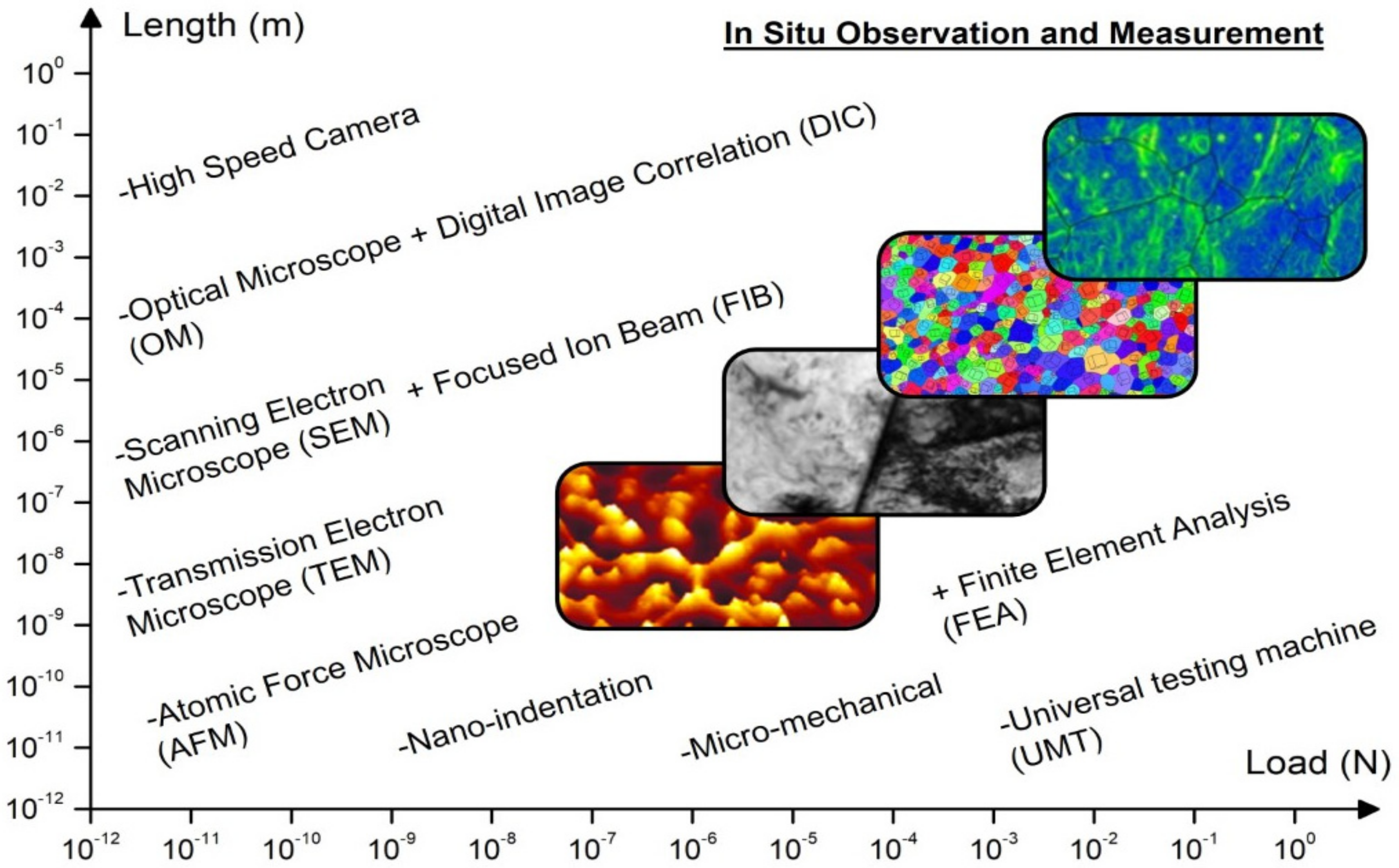
2. In Situ Assessment Techniques

The mechanical characterization of materials is an essential stage in improving its performance and for the development of advanced materials and processes. In addition, the recent advanced applications require materials of high functionality along with deep knowledge of these materials’ responses multi-length scales [30]. In situ testing is a highly effective approach to detect and interpret the mechanical behavior of materials at different length scales, loading scenarios, and environmental factors. The in situ approach has amassed great attention during recent decades to efficiently characterize the mechanical behavior of materials. Some of the former research works even date back to the 1950s and 1960s. For instance, one of the early investigations was conducted by Gene et al. [31] to study the deformation of metal crystals (e.g., gold, copper, and aluminum) by utilizing a Nano-stylus (~100 nm in diameter) and the SEM technique. It was noted that by pressing the Nano-stylus against the specimen surface, no deformation occurred until the critical load was attained. The induced pressure that triggered the material deformation was remarkably higher than the hardness of the bulk material. This is considered to be one of the earliest studies to demonstrate the size effect on the behavior of materials, which is currently a very common research field (e.g., the nano-indentation testing of materials) [30]. In 1985, Bangert et al. [32] developed an ultra-microhardness tester fitted within an SEM chamber with a load range between 50 μN and 20 mN. The developed equipment permitted the testing of material samples of various dimensions and morphologies. Based on the work conducted by Bangert et al. [32], the low-load indentation approach has become a common method to study the creep behavior of different materials [33,34]. The work carried out by Gene et al. [31] using a sharp stylus to study the micro-deformation behavior of materials was significant and has paved the way for additional developments in the field of in situ nanotribology of materials [30]. Currently, in situ scratch or sliding experimentations are commonly exploited to evaluate the tribological response of materials with high monitoring and measurement capabilities (e.g., force/displacement measurement and friction plots) [35,36]. In 1956, Hirsch et al. [15] were among the early researchers to record the dislocation movement using the TEM method while removing the condenser aperture. The dislocations were detected to move along traces of (111) slip planes, while the deformation mechanism of cross-slip by screw dislocations has been recorded regularly [15,16]. This was considered to be the foremost visual evidence of the deformation mechanism of dislocation glide on slip planes [30]. Subsequently, testing procedures, including straining, heating, and cooling stages, have been developed to monitor the activity of dislocation within materials inside TEM [37,38,39]. Moreover, the dislocation movement at the crack tip has been investigated through in situ testing by Ohr [40]. It was found that during the early crack propagation stage, dislocations were emitted from the crack tip generating a dislocation-free zone. Further crack propagation occurred via a combination of plastic and elastic mechanisms. The plastic process of crack opening was generated by dislocations emitted from the crack tip, while the elastic phenomenon was detected by the observed brittle fracture in the dislocation-free zone. In 1980, Mindess et al. [41] used in situ SEM coupled with a designed device to test wedge-loaded compact tension specimens of mortar to study its crack growth behavior. In situ SEM enables the observation of crack initiation and extension, which was found to be very complicated mechanisms and cannot be accurately described by simple fracture mechanics models. In addition, in situ testing monitored the crack branching process, where only one active branch exhibited further extension and wideness, and the inactive branch cracks did not experience any further extension by the main crack. Nowadays, many investigations are conducted to investigate the crack formation and growth in varied materials, and in situ studies critically contribute to this research field [42,43].
The research concerning real-time testing of coatings is being conducted through exploiting different imaging and data-monitoring techniques such as SEM, TEM, AE, and DIC systems. A schematic representation to outline the different imaging tools used in situ monitoring technique at different length scales along with in situ mechanical instrumentations which permit testing of materials under varied force scales, is shown in Figure 1. For imaging, optical microscopes (OM), SEM, and TEM are used, which are combined with mechanical testing tools, e.g., AFM, nanoindentation, micro-tensile stage, and traditional tensile testing using a high-speed camera and the DIC analysis method. Worthy of mention is that the AFM technique is conventionally used as a highly accurate and sensitive microscope for surface imaging [44,45]. In addition, AFM can be utilized as a testing tool to apply and measure mechanical loading with an impressive force resolution (up to 10 nN) for nano/micro-sized samples machined by FIB technology using the AFM cantilever sensor [2,46,47]. For coatings, most in situ studies are being conducted via the combination of a micro-tensile/bending stage for mechanical testing and an optical microscope (OM)/SEM for imaging. In recent years, we have also seen an increasing number of in situ tests of even smaller sample sizes with the use of focused ion beam (FIB) to machine micro-sized samples, including micro-tensile samples, micro-cantilevers, and micro-pillars from coatings.
As a widely used tool, SEM generates magnified images by projecting a high-energy beam of electrons on the sample’s surface [48]. When the electron beam hits the surface of the sample and interacts with the material’s atoms, it generates signals (e.g., X-rays, secondary/back-scattered electrons SE/BSE) that contain information about the sample’s composition, structure, and surface topography. The secondary electron signals tend to be highly localized at the impact point of the primary electron beam, allowing one to record the surface of samples with images of high resolution below 1 nm. The BSE signal has much higher energy than the SEs, hence they can emerge from deeper locations in the sample resulting in BSE images of lower resolutions than SE images. However, the BSE combined with the spectra generated from the characteristic X-rays are usually used in analytical SEM, because the intensity of the BSE signal is strongly related to the atomic number (Z) of the sample [49]. Moreover, the BSE imaging mode can recognize different chemical compositions in the material by the compositional contrast. Since elements with a high atomic number tend to backscatter electrons more strongly than elements with a low atomic number, and thus appear brighter in the image [30,50]. The spatial resolution of the SEM is dependent on the electron spot size, which is, in turn, dependent on the electrons’ wavelength and the electron-optical system that produces the scanning beam. Furthermore, the resolution is affected by the size of the interaction volume between the sample material and the electron beam. The SEM resolution is not high enough to image individual atoms as compared to TEM, because the SEM electron spot size and the interaction volume are both large compared to the distances between atoms [49].
TEM reveals deformation mechanisms at an atomic scale based on the crystallographic structure of different materials [30]. The TEM samples should be electron-transparent and typically have a thickness of less than 100 nm while ensuring its ability to withstand the high vacuum that exists within the instrument [30,48]. Real-time monitoring using TEM is a very useful method to investigate dislocation dynamics during mechanical loading of materials [51]. Hence, the net dislocation densities in specimens during deformation can be determined, permitting deep insight into the undergoing plasticity. TEM imaging is limited to 30 frames/second, which restricts its capability to record the fast deformation events that occur [30]. Alternatively, the dynamic TEM (DTEM) technique has a time resolution in the order of tens of nanoseconds that allows recording fast snapshots of the induced dynamic deformation processes [52]. For obtaining-higher resolution images using TEM, the samples should be thinner, along with using incident electrons of high energy. TEM can attain an image resolution of 0.05 nm at magnifications above 50 million [53]. The high-resolution transmission electron microscopy (HRTEM) has the capability to determine the position of atoms within materials, which makes it an effective tool in the nanotechnology research field (e.g., the development of semiconductor devices) [54]. In TEM, contrast can arise from variation in the density or thickness from position-to-position, atomic number, crystal structure or orientation, and the energy lost by electrons upon passing through the sample. Each contrast mechanism can provide a different kind of information. Hence, TEM can detect various nanometer- and atomic-resolution information, revealing the type, position, and bond type of atoms to each other.
Other techniques that have been utilized to monitor the mechanical response of coatings during in situ examination include AE [55,56] and DIC systems [57,58]. During the deformation and cracking process, AE signals are developed by the elastic stress waves generated inside the material, which are detected by AE sensors. Many researchers studied the relation between the characteristics of AE signals and the corresponding deformation and fracture modes [6,19,55,56]. The AE system is a preferred sensing platform for monitoring internal failure or fiber breakage during straining of the material. For instance, these signals can be related to the damage initiation and evolution prior to the final fracture of tested samples, permitting the monitoring of the coating and substrate response under loading [19]. In DIC, the strain distribution over the coating’s surface is measured by tracking random speckle patterns on the surface of tested samples. This technique is suitable for continuously monitoring the changes in the deformation fields under mechanical loading. Coupling a DIC system with the AE technique has been widely used to investigate the localized plastic strain evolution, crack profile, and the full strain field of bulk materials [19].
In situ testing methods have now become an indispensable approach for material scientists and engineers. The idea of applying these new techniques to coatings and thin films has just emerged during the last few years. This exciting new virgin field awaits exploration by more surface engineers that are equipped with high-performance computational modelling, high-throughput coating deposition technology, and advanced materials testing/characterization methods, all of which have greatly reduced the research and development cycle of a new coating from years to months/days. In the following two sections, we will thoroughly review the most recent studies in this field, which can be divided into two main categories, namely tensile and bending testing.

3. In Situ Tensile Testing of Coatings

Unidirectional tensile testing is essential experimentation to understand the evolution of mechanical characteristics and fracture behavior of coatings at different temperatures. The in situ approach linked to tensile testing allows us to monitor the deformation and failure mechanism that arises upon the thermomechanical loading of materials. Real-time tensile testing has been utilized to determine important mechanical properties such as Young’s modulus, yield strength, fracture strain, and strength for different coatings (e.g., thermal barrier coatings (TBCs), composite and metallic coatings) at both room and high temperatures [10,22,59]. Moreover, the in situ method was used to predict the sudden and catastrophic failure of coatings through the determination of fracture toughness as a crucial damage index [7,60,61,62]. Furthermore, to differentiate between varied mechanisms that occur inside and at the interface of materials due to thermal and mechanical loading conditions [7,59], in situ tensile experimentation has been exploited to examine the effects of chemical composition [10], heat treatment [22], temperature dependency [59], substrate properties [12], and the deposition process [1] on the cracking behavior of coatings. Depending on the tensile sample size, this section has been divided into three parts: (1) Macro-tensile that mainly uses samples that can be manufactured using conventional machining process and normally have gauge lengths in the mm to cm range (sub-divided into room- and high-temperature experimentation); and (2) micro-tensile and (3) nano-tensile, which often use micro- and nano-sized samples that can only be prepared with the use of FIB, while the latter is tested in TEM.

3.1. Macro-Tensile Testing

3.1.1. Room Temperature Experimentation

Real-time imaging coupled with uniaxial stretching provides valuable information that can help us better understand and distinguish various mechanisms activated in the coatings upon mechanical loading [30]. For instance, the in situ approach was used to understand the influence of coatings’ composition on its deformation and fracture behavior under uniaxial tension. Xu et al. [10] investigated the influence of tungsten carbide (WC) content as a reinforcement on the uniaxial tension properties of an Ni-based matrix coating deposited on steel substrates through laser cladding. The tensile tests were performed inside SEM. It was found that the increase in the volume fraction of WC particles decreases the tensile properties of the composite coatings (e.g., ultimate tensile strength) and increases the number of through-width cracks as shown in Figure 2. In situ SEM observations clearly demonstrate that this behavior was attributed to the initiation of cracks from WC particle sites (bright and spherical phases), and then propagated throughout the coatings as indicated in Figure 3. This phenomenon occurred due to the formation of stress concentration fields in the WC particle sites or near the WC particles, which was also confirmed by using finite element analysis (FEA) [10].
Mukherjee et al. [9] studied the influence of Graphene Nano Platelets (GNPs) as reinforcements in a Nickel Aluminide (NiAl) coating to achieve a better strength/ductility combination. The NiAl-GNP free-standing coatings were developed by plasma spraying over a polished substrate, and dog bone samples were fabricated from the coatings using wire Electric Discharge Machining (EDM) with the dimensions of 29 mm overall length and 0.8 mm thickness. Real-time tensile experimentation using a Field Emission Scanning Electron Microscope (FE-SEM) was performed to investigate the strengthening mechanism. The addition of GNPs in the NiAl coating improved various mechanical properties. For instance, the NiAl-GNP composite coatings exhibited 60% improved tensile strength and 25% higher ductility through the addition of 1 wt% GNPs. The improved strength was suggested to be owing to the strong interfacial bonding between the GNPs and the metallic matrix as well as the increased dissipation of fracture energy during the tearing and shearing of GNPs as shown in Figure 4. The utilization of the in situ SEM technique has revealed that shearing and tearing of GNPs contributed to the strengthening mechanism of the coating, which cannot be observed otherwise.
In addition, the effects of post-coating heat treatments on the fracture of coatings have been investigated by many researchers using real-time tensile testing methods [21,22,63]. Bouaziz et al. [22] studied the influence of the annealing temperature (i.e., 400 and 600 °C) on the cracking behavior and interfacial debonding of the brittle nickel/phosphorus (Ni-P) coatings deposited on a ductile steel substrate using in situ tensile testing in an SEM chamber. For as-deposited Ni-P coatings (unannealed samples), the crack is initiated on the surface of the coating at a small strain level, leading to debonding of the coating. The spallation of the as-deposited coatings at a small strain level was caused by the poor adhesion to the substrate as shown in Figure 5a. Meanwhile, in the annealed samples, the Ni-P coatings were subjected to multiple parallel cracks due to the plastic strain localization of the ductile substrates. Subsequently, slanted cracks formed, which could be attributed to the shear stress generated by the necking of the steel substrate as presented in Figure 5b,c. The crack density increased during uniaxial straining and later reached saturation a high strain level. Furthermore, it was found that the heat-treated samples at 600 °C have a higher crack density as compared to samples treated at 400 °C and as-deposited Ni-P coatings at the saturation stage [22]. It can be concluded from this in situ SEM observation of the coating’s surfaces that the damage mechanism of Ni-P depends on the microstructure and adhesion between the substrate and coating. In addition, the treated specimens at 600 °C had the highest adhesion between the Ni-P coating and the steel substrate. Singh et al. [63] investigated the effect of electroplating on 316L steel substrates with Ni and Cu interlayers as well as post-heat treatment on properties of cold-sprayed Cu coatings and revealed the fracture behavior of the coatings via in situ tensile SEM. It was demonstrated that the heat treatment enhanced the coatings’ properties in general. Moreover, it was revealed that the coating failure occurred as a result of the crack initiation from the multiple-splat boundaries and its subsequent propagation along the splat boundaries. However, crack propagation was observed to be obstructed after heat treatment due to inter-particle diffusion.
Zou et al. [1] investigated the effect of the coating depositing process on the fracture behavior and analyzed the fracture process of crack formation and growth between a Plasma Electrolytic Oxidation (PEO) ceramic coating (i.e., Al2O3) and ductile substrate (i.e., aluminum) through the in situ tensile SEM method. The results obtained from the tensile tests of bare and PEO-coated aluminum samples illustrate that PEO cladding decreased the strength and ductility of the substrate material, while slightly improving the modulus of elasticity. The real-time imaging for fracture behavior recorded by SEM showed that cracks initiated at the bottom of ‘over-growth’ regions at the coating/substrate interface as shown in Figure 6a. Then, the crack propagates to the coating surface directly and the crack opening starts to increase with further straining. However, it is observed that the crack propagates into the substrate rather than along the coating/substrate interface (see Figure 6b,c, indicated by pink arrows). The crack opening and propagation continue to extend further inside the substrate as shown in Figure 6d (red and yellow arrows). Finally, upon increasing the tensile load to the critical value, fracture occurs (Figure 6e,f). Furthermore, it was found that the thicker ceramic coating tends to exhibit earlier cracks due to the larger stress concentration [1]. The cracks are more likely to propagate into aluminum substrates rather than the coating/substrate interface as shown in Figure 6d, indicating the superior bonding between coatings and substrates.
Other researchers have studied the cracking behavior of coating systems as a dependency of the coating thickness using real-time monitoring approaches. In situ fragmentation tensile tests were performed for atomic layer deposited (ALD) coatings of TiO2 and mixed oxides of TiO2 and Al2O3 with different thicknesses on polymer substrates to observe these coatings’ cracking behavior by da Costa et al. [64]. It was found that the thinner coatings exhibited multiple cracking as shown in Figure 7, which resulted in reduced interfacial and cohesive strength. A further investigation was conducted by da Costa et al. [60] to study the transverse ridge cracking mode of thin brittle coatings on ductile polymers using tensile tests coupled to a DIC system. Ridge cracking developed in the transverse direction due to the variation of the lateral Poisson’s ratio in the coating and substrate, resulting in a transverse stress component. In addition, it showed that ridge cracking can be used to estimate the fracture toughness for thin coatings. Rochat et al. [65] performed in situ tensile tests inside SEM to determine the failure behavior of ultrathin silicon oxide coatings (~10 nm) deposited on polymer substrates. Prior to in situ tests, a conductive gold layer of different thicknesses was deposited on oxide coatings to prevent charging phenomena due to the insulating nature of the oxide/polymer material. It was found that the saturation crack density reduced with rising gold layer thickness. Therefore, it is important to investigate the influence of conductive layers used in the sample preparation of ultrathin films because it greatly affects the results. In fact, the conductive layer may change the cohesive strength of the oxide coating as well as the transfer of the stress from the polymer substrate to the oxide coating. Chen et al. [17] explored the crack propagation of composite coatings (comprised of FeAl, Al, and Al2O3 layers) on aluminized steel substrates using in situ tensile testing. It was found that vertical cracks developed at the substrate/FeAl layer interface, and then the subsequent propagation of cracks to the top layer of the ceramic coating (i.e., Al2O3) was hindered by the plasticity of the Al middle layer. Hence, the thickness ratio of the middle/top coatings (Al layer/Al2O3 layer) was considered to enhance the strength and toughness of the aluminized steel. Chen et al. [66] previously studied the cracking behavior of titanium nitride (TiN) coating on 304 stainless-steel substrates using tensile testing inside SEM. During the uniaxial straining process, the cracking behavior of the TiN coating exhibited four consecutive and distinct stages, i.e., multiplication, stabilization, cross-linking, and spallation. Moreover, a cracking model has been used to effectively predict the average crack spacing detected in the TiN coating, which was in good agreement with the in situ observations [66].
The material characteristics of the substrates play a critical role in defining the deformation and fracture behavior of coatings under tensile straining. Based on in situ tension observations using SEM, Rehman et al. [12] concluded that the stress transferred from the ductile substrate to the brittle coating layer was dependent on elastic/plastic characteristics of the substrate and coating. The normal cracking propagates in coating segments and their delamination relies on the transferred stress at the substrate/coating interface and the varied sizes of coating segments along with the properties of the substrate and coating material. Additionally, the increase in the value of the Young’s modulus ratio Ecoat/Esubstrate results in a decrease in coating strain generation and vice versa. Zhu et al. [8] performed in situ tensile tests inside SEM to measure the elastic modulus of anode/cathode coating materials as part of studying the deformation behavior of lithium-ion battery components. The in situ mechanical testing using the SEM method was an effective approach in capturing the deformation mechanism of the surface for anode/cathode components. In this work, the anode (i.e., copper foil) was coated with graphite coating layers, while the cathode (i.e., aluminum foil) was coated with an NMC (nickel-manganese-cobalt) coating. The polyvinylidene fluoride-based (PVDF-based) binder was used for both electrodes with different weight percentages for each electrode (i.e., less than 5 wt% for the anode and around 25 wt% for the cathode). It was found that the deformation behavior of anode/cathode coatings depends on the behavior of the binder. For instance, the cathode develops micro-cracks on the surface prior to the final rupture, while in the anode, a sudden fracture occurred in the later stages of straining without micro-crack formation as indicated in Figure 8. This can be attributed to the fact the particles in the coatings are almost rigid and all deformation occurs in the binder. For the anode, fracture occurred suddenly because there is not enough binder to transfer the load, while for the cathode, the fraction of the binder is high, resulting in much more deformation before the final rupture.
Völker et al. [61] demonstrated that macroscopic in situ SEM tensile tests permit a quick and efficient method for monitoring fracture toughness in hard coatings as compared to accurate but time-consuming micro-bending beam experiments. In situ SEM tensile tests were carried out on TiAlN and VAlN coatings, each applied on ductile Cu-substrates. The strain at the crack initiation of the coating was utilized as a representative of the fracture toughness. The tensile experiments show that TiAlN has a higher fracture toughness than VAlN, which was confirmed using micro-bending beam fracture experiments. Ahmadi et al. [67] studied the effect of underlying steel substrates on the fracture behavior of Zn-Al-Mg coatings throughout in situ testing. To monitor the dynamic evolution of damage, real-time tensile and bending tests have been performed inside SEM. It was found that Zn-Al-Mg coatings deposited on high-strength, low-alloy steel (HSLA) exhibited more cracks as compared to those coatings applied on interstitial-free (IF) steel. These were attributed to discontinuous yielding in the HSLA steel developing a heterogeneous deformation resulting in coating cracking, while IF steel substrate deformation was more compatible with the coatings and resulted in better cracking behavior.
Many researchers have investigated the fracture behavior of TBCs during real-time tensile testing using the DIC system and/or AE sensors [19,57,62,68]. The experimental results indicated that surface cracking was often followed by interfacial delamination. For instance, the AE coupled with the DIC technique was used to study the cracking in TBCs under tension by Zhou et al. [19]. It was found that surface cracks initiated and propagated with the increasing tensile strain, and then interface cracks initiated from the roots of surface cracks that eventually reached a saturation state. The evolution of strain fields during in situ tensile testing of TBCs is illustrated in Figure 9. The in situ observations using the DIC system illustrated that the AE signals are related to the failure modes (i.e., vertical cracking, interfacial cracking, and delamination) of the TBCs. Furthermore, it was found that there is a power–law relationship between the strain in the substrate and the corresponding vertical crack density in the coating. Furthermore, the authors defined a damage variable to describe the different fracture stages of a TBC system that occurred as a function of cumulative AE events. Mao et al. [62] studied the fracture behavior of TBCs deposited on a Ni superalloy during in situ tensile tests using DIC and developed a shear–lag model. The in situ DIC measurements allowed us to directly observe dynamic strain fields, surface cracks’ initiation, and propagation as well as predict the mechanical properties of TBCs (e.g., interface shear strengths, fracture strengths, fracture toughness, and fracture energy). Patibanda et al. [69] investigated the real-time tensile and bending characteristics of plasma-sprayed, freestanding TBCs. The strain distribution over the deformed samples was recorded during the testing process using DIC. The tested samples from the same batch showed variations in its mechanical response (i.e., stress vs. strain curve), which could be attributed to the defects in the microstructure. Moreover, the coatings exhibited better bending properties compared to its tensile characteristics. Qian et al. [70] also studied the cracking behavior of plasma-sprayed TBCs during unidirectional tensile loading of a sandwiched specimen via in situ SEM. During the straining process, parallel cracks in the transverse direction were developed in the top-coat layer, and a continuous decrease in the crack spacing occurred until saturation was achieved. After saturation, cracks propagated through the interface between the bond coat and the top coat. Finally, interfacial debonding occurred at the bond coat/substrate interface.

3.1.2. High-Temperature Experimentation

At high temperatures, the deformation and fracture behavior of materials mainly vary and materials generally exhibit better ductility and microstructure changes due to the recrystallization process. Therefore, the in situ technique can provide a considerable approach to understanding the coatings’ response under high-temperature conditions. For instance, the in situ tensile behavior of Cr-coated Zircaloy (Zr-4) for accident-tolerant fuel cladding (ATC) was studied by Jiang et al. [71] using in situ SEM. The cohesive FE approach was also utilized to model the interfacial cracking behavior and numerically evaluate the interfacial fracture strength and toughness. The Cr coating was found to exhibit a brittle cracking mode under room-temperature conditions. However, some short interfacial cracks started to propagate from the vertical crack tips during severe straining driven by interfacial peeling and shear stresses. The Cr coating exhibited enhanced plasticity at high temperatures, which may result in different cracking modes [7]. Hence, Jiang et al. [7] further analyzed the cracking behavior of two ATC coatings (Cr coating and CrN coating) deposited on a Zr-4 substrate at room temperature and 400 °C through real-time tensile testing. Under the performed thermomechanical tests, it was found that the Cr coating showed a brittle-to-ductile transition when the temperature was increased from room temperature to 400 °C, while the CrN coating exhibited a brittle fracture mode at both temperatures as represented in Figure 10. Cr coatings demonstrated higher crack resistance compared to the CrN coating at both temperatures, owing to the higher fracture toughness and ductility of Cr, as well as better deformation compatibility between the Cr coating and Zr-4 substrate. Further investigation was conducted by Jiang et al. [59] to deeply understand the temperature-dependent deformation and fracture of Cr coatings (from 25 °C to 500 °C) using the in situ SEM tensile testing method that was demonstrated to be significant. Using in situ SEM observations, it was found that the Cr coating exhibited a brittle-to-ductile transition temperature (BDTT) at 450 °C. Below the BDTT, the Cr coating showed a brittle fracture as featured by surface cleavage cracking, while increasing the deformation temperature resulted in improved ductility and reduced tensile strength of the coating. At temperatures close to the BDTT, in situ SEM images detected both channel cracks and small separated cracks that developed in the Cr coating. Above the BDTT, the Cr coating failed in a completely ductile manner at higher tensions. In addition, the ductility and strength of the coated Zr-4 specimens were enhanced as compared to uncoated specimens. Ma et al. [72] also studied the influence of ATC on the fatigue behavior of the Zr-4 alloy at 400 °C via in situ tensile tests inside SEM incorporated with FE analysis. It was found that the Cr coatings significantly improved the fatigue resistance, while the TiCrAlN coatings noticeably reduced the fatigue life. This can be attributed to the cracking behavior and fracture toughness of each coating. The TiCrAlN coating, which was characterized by low fracture toughness, permitted early crack initiation in the Zr-4 substrate, and hence had a short fatigue life. In contrast, the Cr coating, which has a much higher fracture toughness than the TiCrAlN coating, resisted the crack initiation leading to longer fatigue life.
Isothermal tensile tests conducted at different temperatures were combined with the AE method to study the fracture behavior of AlSi-coated Press-Hardened Steel (PHS) [6,73]. The cracking mode of the AlSi coating was identified by means of AE sensors during the deformation process. High-energy AE signals were related to the opening fracture mode (Mode I), while low-energy signals were linked to interfacial cracking (the formation of ridges, Mode II) as shown in Figure 11 [6]. The cracking that occurred in the AlSi coating was primally attributed to the formation of intermetallic compounds (i.e., FeAl and Fe2Al5) through Fe-diffusion, which also resulted in void formation in the coatings [6,73].
Ray et al. [56] studied the mechanical characteristics of the NiCoCrAlY bond-coat during room- and high-temperature uniaxial tension tests with the use of AE signals to measure DBTT. The acoustic emission method was used for detecting the initiation of the first cracking phenomenon in the bond coat. The acoustic emission signals along with the load–displacement plots were analyzed for both samples with and without the bond coat. It was found that no acoustic emission activity was observed within the elastic limit of load–displacement plots for the samples without the bond coat, which is not the case for the samples with a bond coat, which provides justification that the bond coat cracks first within the elastic limit of the bond-coated composite samples. This observation was used to determine the DBTT of the bond coat, which was around 650 °C and close enough to values reported in the literature. Appleby et al. [74] investigated the thermomechanical response of Environmental Barrier Coating (EBC)-coated Ceramic Matrix Composites (CMCs) using digital image correlation, acoustic emission, and electrical resistance measurement systems. It was demonstrated that Electrical Resistance (ER) measurements can be efficiently used to monitor the in situ damage evolution of SiC/SiC CMCs during elevated-temperature testing. The electrical resistance response increased because of the progression of damage. This can be attributed to the fact the deformation stresses resulted in the formation of matrix cracks, as well as fiber breakage, resulting in a rapid increase in ER just prior to the final rupture. For further elaboration, the increased number of matrix cracks upon straining resulted in smaller lengths of the conductive undamaged composite, separated by longer lengths of highly resistive fiber-bridged transverse cracks. This mechanism is responsible for impeding the electricity flow of composite coating. The strain fields captured by DIC attained good agreement with the AE energy analysis in terms of failure location and distribution.

3.2. Micro-Tensile Testing

Reichardt et al. [23] investigated the influence of He+2 ion irradiation on the mechanical characteristics of thin-foil Ni single crystals utilizing the in situ micro-tensile experimentation in SEM. The micro-tensile samples fabricated by FIB were loaded in tension along the slip direction namely [100], up to fracture. The irradiated samples experienced higher strength and lower ductility as compared to the unirradiated material. Confirmed by TEM observations, the He bubbles were found to hinder the dislocation movement, resulting in noticeably varied deformation behavior with the irradiation dosage. Brittle fracture was detected at the surface near the peak damage regions, while plastic deformation in the regions with a smaller dose was more significant. In the sample of higher dosage of 19 displacements per atom (dpa), slip bands extended to the peak damage region. TEM imaging detected the blocking of the slip bands at the peak damage zone, before the He concentration area with bubbles. The removing of the He bubble area and peak damage zone with FIB provides an opportunity to attain slip-band propagation through the remaining thickness of the specimen. SEM images of the micro sample irradiated with 6 MeV He+2 ions to a fluence of 2 × 10¹⁷ ions/cm2 after tension are shown in Figure 12c,d, which demonstrate an obvious brittle fracture mode after irradiation. Figure 13 shows the stress–strain curves for the non-irradiated and irradiated micro-tensile samples. Before irradiation, the sample showed ductile behavior with significant necking enabled by the formation of alternating slip steps on multiple slip systems as shown in Figure 12b. As the sample oriented along the <001> axis, the slip events occurred on the {111} planes, and its traces are close to 45°. After radiation, dramatic changes in deformation behavior can be observed. Although the material’s strength is increased, the “exit surface” of the sample began to fracture in a brittle manner (see Figure 12c) at a very small strain of about 2%. The irradiated nickel film is no longer ductile, and the radiation made the surface brittle.
To study the mechanical characteristics of thin nitride compound layers, micro-tensile smooth and notched specimens with dimensions of 77 µm × 11.3 µm × 5.3 µm (length × width × thickness) fabricated by FIB were tested inside SEM by Arnaud et al. [75]. The in situ tensile experimentation combined with the DIC system was exploited to determine the elastic modulus, and the Poisson’s ratio of the tested thin surface layer. Additionally, the FEA method for the micro-notched sample considering the notch radius and surface roughness was conducted to estimate the tensile fracture toughness of the studied compound layer. The technique proposed by the authors using the FIB micro tensile experimentation combined with the DIC system allows one to locally determine the mechanical characteristics of the thin-layer coating and study its anisotropic behavior regarding mechanical properties such as elasticity, plasticity, and fracture toughness. Figure 14a shows the DIC measurement system carried out to determine the strain deformation in the tensile direction (see Figure 14c) across the effective pulling area. A rather homogenous strain distribution is recorded with a mean residue of around 6% of the grey scale as shown in Figure 14b. This rather high residue may be interpreted by brightness and contrast fluctuations during the test.

3.3. Nano-Tensile Testing

TEM is always used with special requirements regarding sample thickness and transparency, which confined its utilization, and therefore TEM is not widely used in coatings and only very few publications utilize the TEM technique. Hence, the TEM investigation of coatings is considered a marginal phenomenon. For instance, Cai et al. [4] used in situ TEM tensile testing to study the fracture of a BCC high-entropy alloy coating (See Figure 15). The fracture evolution recorded by the TEM technique showed an obvious movement of dislocations (represented by the red arrows at t = 30 s and t = 46 s in Figure 15). Hence, it can be assumed that the dislocation motion caused by tensile loading may be the dominant factor for crack formation, resulting in sudden fracture. Moreover, the sudden failure occurred at t = 96 s, and to find the retained plastic strain (εplastic), two green rows were placed to mark the origin of the fracture as shown in Figure 15. The tensile samples were prepared by FIB with approximate dimensions of 4 µm × 700 nm × 90 nm (length × width × thickness). The mechanical characteristics of high-entropy alloy (HEA) coatings such as Young’s modulus, fracture strength, and ultimate elongation were measured. The evolution of dislocation movement within HEA could be linked to the induced fracture during testing. In addition, the HEA coating exhibits a cleavage fracture mode (i.e., brittle fracture) with the cleavage plane of {112}. The stress–strain behavior obtained demonstrated linearity conforming brittle failure; however, a minimal deviation in the linearity attributed to plastic deformation occurred prior to fracture. In a further investigation conducted by Cai et al. [5], the focused ion beam technique was used to cut tensile samples at the nano scale from the HEA coating, and then these samples were subjected to uniaxial tension inside TEM to observe the coating deformation behavior. It was indicated that dislocations accumulated at the interface between the HEA phase (BCC) and (Co, Ni) Ti2 compounds (FCC) within the HEA coating, and a crack propagated through the phase interface resulting in the final rupture.
In summary, in situ tensile testing has proven to be an efficient technique to offer deep insight into coatings’ deformation and fracture behavior and improve the potential to achieve better performance and functionality of these materials. However, tensile experimentation primally uses smoothly shaped specimens, which enable testing material under a uniaxial stress state only. Therefore, there is a need to utilize notched and equibiaxial-shaped samples more to extend the functionality of coatings and thin films under varied stress triaxiality states ranging from pure shear to balanced biaxial stress states. In addition, there is a need for more investigations to be made on the behavior of coating materials during elevated temperatures (more than 600 °C) and high deformation rates using the SEM technique to compensate for the thermal electrons’ effect on the imaging quality.

4. In Situ Bending Testing of Coatings

The in situ bending technique has been utilized extensively to quantify the damage behavior and material characteristics (e.g., stiffness, flexural strength, and modulus) of coatings and thin films. Bending experimentation provides a good opportunity to test the material response under different stress states (i.e., tension and compression). Moreover, it is a highly effective method to observe crack initiation and propagation at the surface and through the thickness of the coatings, as well as evaluate the stress intensity and strain energy at the developed crack tip. Real-time bending testing has been utilized to measure mechanical properties, detect different failure modes, and quantify material resistance for cracking. The coatings that show high resistance to cracking exhibited high fracture toughness values and better adhesion to the substrate material under thermomechanical loading. The bending-driven fracture is considered to be an efficient technique to examine the durability of coatings at different temperatures [69,76,77], cracking behaviors [69,78,79], thicknesses [80], and deposition method effects [18].
The real-time bending testing methods (e.g., three-point and four-point bending) can be used to explore the fracture behavior of coatings as well as measure their mechanical properties such as bending strength and flexural modulus. During the bending test, the stress state varies through the thickness, and the failure strength is mainly affected by the surface/edge microstructure and defects that permit early fracture. Hence, it is important to simultaneously monitor the deformation and failure mechanics in the coatings, both through the thickness as well as on the surface. SEM and DIC are the most widely used imaging and monitoring techniques to reveal the deformation and failure behavior inside and outside the tested specimens, as well as determining the mechanical properties of coatings under a bending situation. In particular, the bending-driven failure test is an efficient method to evaluate the quality and load-bearing capacity of a TBC system.

4.1. Macro-Bending Testing

Chen et al. [76] investigated the stiffness of a free-standing air plasma-sprayed (APS) TBC using the in situ three-point bending technique inside SEM. It was found that the TBC beam exhibits nonlinear and inelastic deformation behavior during the bending process. The measured in-plane elastic modulus varied with thermal exposure due to micro-crack nucleation from microstructural imperfections during sintering. Based on the in situ observations, the low elastic modulus of the APS TBC was reported to have an intra-splat cracking mode. Martins et al. [81] studied the effect of bond coat (BC) topographical features on the fracture mechanics of APS TBC using an in situ modified four-point bending test to determine the stress intensity and strain energy at the developed crack tip. The in situ bending experimentation allowed us to characterize the crack propagation at different BC topographies, and it showed that BC topographical features affect the crack propagation path and velocity. Patibanda et al. [69] utilized in situ four-point bending experimentation to explore the failure behavior of TBC samples under varied stress states and determine the mechanical properties of TBC under bending conditions such as flexure strength and bending modulus. It was found that the values of bending strength and modulus were higher than those obtained from uniaxial tension trials. This was attributed to the stress state uniformity across the tensile sample while varied stress states were developed during bending along the sample’s thickness resulting in a higher failure strength. Yang et al. [78] assessed the damage evolution of as-sprayed and pre-oxidized TBCs using real-time three-point bending with the aid of AE and DIC monitoring systems. The coatings’ interface and surface fracture toughness were evaluated based on the detected AE signals and strain fields as shown in Figure 16. It was shown that there is linearity between the released fracture energy and the corresponding AE events for the tested TBCs samples. The slope of this relationship depends on the properties and failure mode of TBCs.
Planques et al. [82] characterized the mechanical response of the TBC system using three-point bending tests coupled with the two-dimensional DIC method. The DIC system was utilized to detect the evolution of surface strain distribution besides revealing the location of crack initiation and propagation paths in TBCs. In the performed bending tests, the load was applied either on the coating side or the substrate side leading to a compression or tension stress state within the ceramic coating, which resulted in different failure modes. Under the tension stress state, a segmentation crack and delamination occurred, while the compression of the TBC led to delamination cracks and spallation. Jiang et al. [79] explored the fracture behavior of a double-ceramic-layer TBC system through experimental and analytical procedures. In situ four-point bending tests with the aid of the SEM method were carried out to monitor the cracking features. Vertical and interfacial cracks were simultaneously developed during bending tests, giving rise to the critical crack density at which the failure of the double-ceramic-layer TBC system occurred. Moreover, an analytical model was established to estimate the critical crack density based on a modified shear-lag model and interfacial fracture mechanics. Zhu et al. [77] studied the durability and fracture mechanism of APS TBCs. Real-time, high-temperature, three-point bending tests coupled with the DIC technique were used to assess the fracture toughness and elastic modulus of TBCs. The evolutions of mechanical characteristics of TBCs at high temperatures were attained. It was revealed that increasing the testing temperature has the effect of reducing the TBC elastic modulus and fracture toughness, while increasing the interfacial fracture toughness. The crack initiation and propagation of the APS TBCs using the DIC system during the bending test are presented in Figure 17. The cracking behavior observed started with the initiation of surface cracks, followed by the formation of interfacial cracks between the top coat and the bond coat, and finally, further propagation of interfacial cracks.
Mao et al. [24] investigated the fracture mechanism of freestanding (Gd0.9Yb0.1)2Zr2O7 GYbZ coatings using in situ three-point bending and single-edge notched beam tests with the aid of the DIC monitoring system at different temperatures (up to 1500 °C) to evaluate the effect of thermomechanical loading on the evolution of coatings’ fracture strength, flexural modulus, and fracture toughness. The extended finite element method (XFEM) was used to predict the critical energy release rate of GYbZ coatings during the tests. Wan et al. [83] studied the failure behavior of the freestanding Yttria Stabilized Zirconia (8YSZ) coating during in situ single-edge notched bending tests (SENB) with the help of the DIC technique (See Figure 18a). The crack propagation and dynamic strain fields around a pre-existing notch region were detected by the DIC system giving rise to accurately determining the critical bending loads of the tested samples (See Figure 18b). Musalek et al. [84] performed in situ three-point bending tests using SEM to investigate the failure mechanisms of free-standing plasma-sprayed alumina and stainless-steel 316L coatings. The in situ observations were supplemented by fractographic analysis of fractured samples. The cracking mechanisms were identified as intra-splat cracking and inter-splat decohesion followed by interlinking of pores and cracks, mutual splat sliding, and pore compaction. Regarding the metallic coating, the formation of ductile dimples was detected. Liu et al. [85] measured the fracture toughness of an in situ-formed, carbon-fiber-reinforced, SiC matrix composite coating using SENB tests coupled with the DIC technique. The crack growth of the composite coatings was detected by the evolution of local strain fields monitored by the DIC (ARAMIS) system. It was found that exploiting the in situ carbon interphase method increased the toughness of the carbon-fiber-reinforced SiC composite significantly from 1.7 ± 0.3 MPa m1/2 to 21.3 ± 0.7 MPa m1/2. This was attributed to toughening mechanisms such as crack deflection and fiber pullout.
Jiang et al. [86] explored the fracture of a Cr-coated Zr-4 alloy at room temperature utilizing the in situ SEM three-point bending test and finite element analysis (FEA) method as presented in Figure 19. The in situ three-point bending enables more precise measurements than in situ tensile testing to detect the formation and propagation of vertical and interfacial cracks in the Cr coatings. It is shown that vertical cracks were generated from the coating/substrate interface and then rapidly penetrated through the coating thickness at further loadings. Moreover, due to the induced shear stresses and interfacial peeling, interfacial cracks were developed from the vertical crack tips and spread along the coating/substrate interface as shown in Figure 19. The FE analysis was used to estimate the fracture properties of the Cr coating (e.g., fracture toughness, interfacial fracture strength, and toughness). Jiang et al. [87] investigated the failure behavior of the Cr coating deposited as ATF cladding on the Zr substrate considering the effects of oxidation and diffusion that occur at high temperatures. Real-time three-point bending tests were conducted inside SEM. It was shown that the Cr coatings experienced recrystallization at high temperatures, which significantly improved the coatings’ resistance to cracking. However, due to the simultaneously occurring diffusion induced, intermetallic layers formed at the coating/substrate interface leading to the initiation and propagation of micro-cracks in these layers.
Liang et al. [80,88] studied the failure of a YSZ coating deposited on a superalloy substrate by observing the crack evolution in the coating system using real-time three-point bending tests and SEM imaging. The damage evolution of coatings with different thicknesses and microstructures were investigated, and different failure modes were identified for thinner- and thicker-coating specimens. The major failure mode in thin coatings was multiple transverse cracks, while an interface cracking mode was shown in the thicker coatings [80]. In addition, a damage model to describe the catastrophic failure of brittle coatings was developed based on the conducted experimental tests [88]. Kiilakoski et al. [18] investigated the effect of the coating deposit method (i.e., APS and high-velocity oxy-fuel (HVOF) thermal spraying) on the failure characteristics of Al2O3-ZrO2 coatings through in situ three-point bending inside SEM (see Figure 20) and four-point bending with AE monitoring. The coatings were prepared from two feedstocks, fused, and crushed (F&C), and agglomerated and sintered (A&S). The toughness of coatings was assessed based on the fact tougher coating has better resistance to catastrophic fractures and hence a greater strain limit. It was demonstrated that the coatings deposited by APS had greater fracture strain but an abrupt failure, while in the HVOF coatings, cracking was initiated earlier but proceeded slower with more crack deflections. This varied cracking behavior is attributed to the coarser microstructure of APS coatings permitting more strain distribution along the tested samples, in contrast to the finer microstructure of the HVOF coatings [18]. Grigore et al. [89] studied the internal stresses developed by a combined magnetron sputtering and ion implantation (CMSII) method to produce the nc-Ti2N/nc-TiN nanocomposite coating. The in situ cantilever method was used to monitor the internal stress during the process of coating deposition. It was found that the CMSII method produced about half the stress generated by magnetron sputtering without the ion implantation technique. TEM was utilized to analyze the structure of developed coatings. It was noted that their structure is featureless, extremely dense, and pore-free. TEM analyses have shown crystallites with a size of less than 10 nm. Wang et al. [90] studied the crack propagation in two coatings (i.e., amorphous coating and composite coating) using the real-time three-point bending test coupled with an optical microscope. The amorphous coating showed brittle fracture behavior in contrast to the composite coating. It was concluded that the composite coating exhibited better strength and fracture toughness as compared to the amorphous coating. Furthermore, it was found that the cracks initiated at pores and then propagated rapidly until reaching complete failure for the amorphous coating, while in the composite coating, cracks mainly initiated around the amorphous carbon phase and propagated gradually across the carbon phase, showing that the crack growth was hindered by the carbon phase.

4.2. Micro-Bending Testing

Micro-bending testing is an effective approach for the measurement of mechanical characteristics at a small length scale and has been broadly exploited to determine the fracture toughness of coatings and thin films [91,92,93,94,95,96]. In addition, the FEA method is often coupled with experimental data to validate the fracture toughness [24,60,62,86]. However, in most of these papers, in situ imaging measurement was not fully exploited, possibly because of the limited information that can be detected during in situ micro-cantilever bending tests using SEM, such as observing slip plan formation and surface fractography. Therefore, this approach is best suited to measure the intrinsic mechanical properties of coatings layers and thin films (e.g., accurate measurement for the interfacial fracture strength).
With assistance from FIB technology, micro-bending testing permits the assessment of small-volume samples to comprehend the deformation and characteristics of localized features. For instance, Schaufler et al. [13] studied the fracture strength and toughness of hydrogenated amorphous carbon (a-C:H) coatings with a Cr adhesion layer on a steel substrate using in situ microcantilever bending experiments as shown in Figure 21. It was found that the adhesion layer has a significant effect on the delamination behavior of coatings. The interfacial fracture strength and toughness of the studied coatings were quantified directly using micro-cantilever bending tests. Chen et al. [97] applied in situ microcantilever beam bending inside SEM to determine the stiffness and fracture toughness of a thermally grown oxide (TGO) on a MCrAlY coating. The utilized technique provided direct measurements on the intrinsic mechanical characteristics of the TGO, eliminating the effect of the substrate and residual stress compared to the nanoindentation testing method. In another investigation by Chen et al. [14], the fracture toughness of the platinum-modified nickel aluminide (RT22LT) bond coat was measured via in situ microcantilever bending tests. Cantilever beams were fabricated by FIB in three microstructurally distinct zones along the coating cross-section and then bent inside SEM as presented in Figure 22. FE modelling incorporated with the experimental observations was used to calculate the fracture toughness. The fracture toughness varies through coating thickness in a manner whereby maximum toughness was found in the middle zone followed by the surface and interdiffusion zones, respectively, as shown in Figure 23. This was attributed to the variation in plastic response prior to failure from one zone to another.
Liu et al. [98] investigated the fracture resistance of CrN-based hard coatings using micro double-cantilever beams (DCBs) fabricated by the FIB method. The microscale DCBs were compressed using an in situ nanoindenter with a 5-µm-diameter diamond punch. It was demonstrated that the fine-grained CrAlN/Si3N4 coating has greater fracture toughness as compared to a conventional CrN coating (nearly double). Furthermore, the authors demonstrated that the compression applied from the top can be translated into tensile loading acting on the crack plane when certain aspect ratios of beam dimensions are preserved. Stable cracking behavior is attributed to the geometries of the double cantilever beam (DCB), where a moment is applied to each of the beams, on either side of the growing crack. The cracking behavior in micro DCBs for CrN and CrAlN/Si3N4 coatings is shown in Figure 24.

4.3. Fractural Toughness Measurements

To evaluate the fracture toughness of coatings, mechanical testing techniques such as bending and tension experimentation have been widely used. The fracture toughness of hard coatings (i.e., TiAlN and VAlN) deposited on ductile Cu-substrates were measured using in situ tensile and micro-bending fracture experiments in SEM by Völker et al. [61]. The results demonstrated that TiAlN exhibited a higher fracture toughness than the VAlN coating, as was mentioned earlier in the previous section on tensile testing. The strain at which cracks start to initiate in the coating material was utilized as representative of the fracture toughness. The tensile experiments show that TiAlN has a higher fracture toughness than VAlN, which was confirmed using micro-bending beam fracture experiments. Therefore, it was suggested that the strain evaluation using in situ tensile testing can be used as a qualitative measure of the fracture toughness of hard coatings instead of the stress intensity in front of the crack tip at crack initiation. Gruber et al. [99] investigated the surface oxidation of nanocrystalline chemical vapor deposition (CVD) TiB2 coatings using in situ micromechanical experiments. The elastic modulus and fracture stress in the TiB2 hard coating prior to and after the oxidation treatment were measured using micro-cantilever bending in SEM. In situ fragmentation tests coupled with SEM and DIC systems were used to estimate the fracture toughness of thin brittle coatings on a polymer substrate by observing the formation mechanism of ridge cracks [60]. Real-time imaging of single-edge notched beam experiments was exploited to measure the fracture toughness of GYbZ coatings at different temperatures using the DIC system [24]. It is shown that the fracture toughness of the brittle coatings increased when increasing the testing temperature up to 1400 °C [24]. During cracking of coatings, AE signals were detected due to the release of locally stored elastic energy. Yang et al. [78] used the in situ three-point bending test along with the AE monitoring method to characterize the fracture toughness of TBCs and analyze its fracture behavior. As mentioned earlier, Zhu et al. [77] evaluated the thermomechanical loading effect on the fracture toughness of APS TBCs via in situ three-point bending with DIC. It was demonstrated that increasing the temperature from 30 °C to 800 °C resulted in decreasing the fracture toughness and modulus of elasticity from 1.31 MPa m1/2 to 1.16 MPa m1/2 and from 20.3 GPa to 13.1 GPa, respectively, while the interfacial fracture toughness increased from 83.7 J/m2 to 156.3 J/m2.
To summarize, the in situ bending technique is important in studying the fracture behavior of coatings as well as measuring its mechanical properties (such as fracture toughness, flexural strength, and Young’s modulus). Furthermore, bending experimentation is the most suitable method to investigate the crack propagation behavior of coatings and evaluate the capabilities of coating materials to withstand mechanical loading. In situ bending provides a great opportunity to examine the adhesion of coatings to substrate materials, recognize varied fracture modes that occur under different thermomechanical loading scenarios, as well as measure the evolution of the mechanical properties of coatings.

5. Future Trends

Currently, the competitive industrial world is creating a rapidly growing demand for enhanced efficiency of the surface characteristics of engineering components that serve under harsh environments (e.g., corrosive, high-temperature, and varied mechanical loading conditions), for applications in the automotive, aerospace, energy, electronics, and power industries [100]. In situ mechanical testing provides a unique opportunity to understand the deformation and cracking behavior of coatings during several harsh loading conditions that simulate in-service situations. Future investigations on the in situ mechanical testing of coatings and thin films could involve:
  • Extending the SEM testing temperature limits to examine the responses of coatings and thin films (e.g., TBCs, EBCs, etc.) under extreme conditions, which will help in maintaining the safety and reliability of the corresponding industrial applications. Furthermore, it will compensate for the low quality of images obtained when the temperature exceeds 600 °C because of thermal electrons.
  • Testing the fracture behavior of coatings and thin films under different mechanical stress states that can be achieved by using notched samples of varied stress triaxialities (ranging from pure shear to plan strain conditions).
  • Since high-entropy alloys introduce promising mechanical, structural, and physical properties, they are becoming a flourishing scientific research field. Hence, more in situ work should be devoted to exploiting HEAs as a coating material to reveal their unique mechanical behavior.
  • The FEA can provide an efficient approach to understanding the thermomechanical behavior of coatings and thin films under complex loading conditions, saving effort and time. Therefore, there is a need for more incorporation of FEA in thermomechanical and fracture analysis of coatings and thin films.

6. Summary

The fracture of coatings under in situ tensile and bending experimentations have been reviewed in this work. The key points (e.g., monitoring techniques, testing method, limits, and future trends) raised in the current review are summarized and allocated in Table 1. Different real-time monitoring techniques have been used by researchers to gain deep insight into the evolution and fracture behavior of mechanical characteristics in the reviewed articles. SEM has been widely utilized to monitor the deformation and fracture mechanisms at both micro and nano scales. The DIC system and AE sensors were mainly used for measuring surface strain fields and detecting stress waves released inside the material, respectively. The deformation and failure of coatings were assessed considering varied factors including the mechanical properties of the substrate and bond material, heat treatment procedures, chemical composition and microstructure, layer thickness variation, thermomechanical loading, and deposition method influences. The coatings that gained greater attention from researchers were primarily TBCs followed by composite and metal alloy coatings and films. Based on the reviewed research articles, there are certain limitations of the current in situ monitoring techniques (i.e., SEM, TEM, DIC, and AE). For instance, the maximum achieved testing temperature using the SEM method is 600 °C. Therefore, further research should be directed to test coatings under temperatures higher than 600 °C, as well as attempts to reduce the effect of thermal electrons on the resolution of recorded images. Moreover, using the in situ TEM technique has special requirements in the tested materials such as electron-transparent and ultrathin samples, and this surely confined the range of tested materials. In the DIC system, materials can be tested under elevated temperatures (up to 1600 °C), but without the ability to capture the deformation and damage mechanisms activated within materials. The AE monitoring technique has a limitation in terms of the need for complex analysis on the acoustic signals and its correlations with deformation and damage events, as well as being easily affected by surrounding noise. Future studies are expected to extend this approach to an increasing number of mechanical properties of interest in surfaces, coatings, and interfaces.

Author Contributions

M.B. proposed this article idea, structured the paper, in addition to revising the paper writing; M.A. and Q.H. were responsible for developing the work plan, data collecting, and analysis, as well as writing the paper; V.J., N.J. and J.N. were responsible for revising and refining this article. All authors have read and agreed to the published version of the manuscript.

Funding

This research was funded by CN Technical Services Ltd. (CN Tech), UK.

Institutional Review Board Statement

Not applicable.

Informed Consent Statement

Not applicable.

Data Availability Statement

Data are contained within the article.

Conflicts of Interest

The authors declare no conflict of interest.

References

  1. Zou, Y.; Wang, Y.; Wei, D.; Du, Q.; Ouyang, J.; Jia, D.; Zhou, Y. In-situ SEM analysis of brittle plasma electrolytic oxidation coating bonded to plastic aluminum substrate: Microstructure and fracture behaviors. Mater. Charact. 2019, 156, 109851. [Google Scholar] [CrossRef]
  2. Liu, F.; Tang, D.M.; Gan, H.; Mo, X.; Chen, J.; Deng, S.; Xu, N.; Bando, Y.; Golberg, D. Individual boron nanowire has ultra-high specific young’s modulus and fracture strength as revealed by in situ transmission electron microscopy. ACS Nano 2013, 7, 10112–10120. [Google Scholar] [CrossRef] [PubMed]
  3. Heiroth, S.; Ghisleni, R.; Lippert, T.; Michler, J.; Wokaun, A. Optical and mechanical properties of amorphous and crystalline yttria-stabilized zirconia thin films prepared by pulsed laser deposition. Acta Mater. 2011, 59, 2330–2340. [Google Scholar] [CrossRef]
  4. Cai, Z.; Cui, X.; Liu, E.; Li, Y.; Dong, M.; Lu, B.; Jin, G. Fracture behavior of high-entropy alloy coating by in-situ TEM tensile testing. J. Alloys Compd. 2017, 729, 897–902. [Google Scholar] [CrossRef]
  5. Cai, Z.; Cui, X.; Jin, G.; Lu, B.; Zhang, D.; Zhang, Z. In situ TEM tensile testing on high-entropy alloy coating by laser surface alloying. J. Alloys Compd. 2017, 708, 380–384. [Google Scholar] [CrossRef]
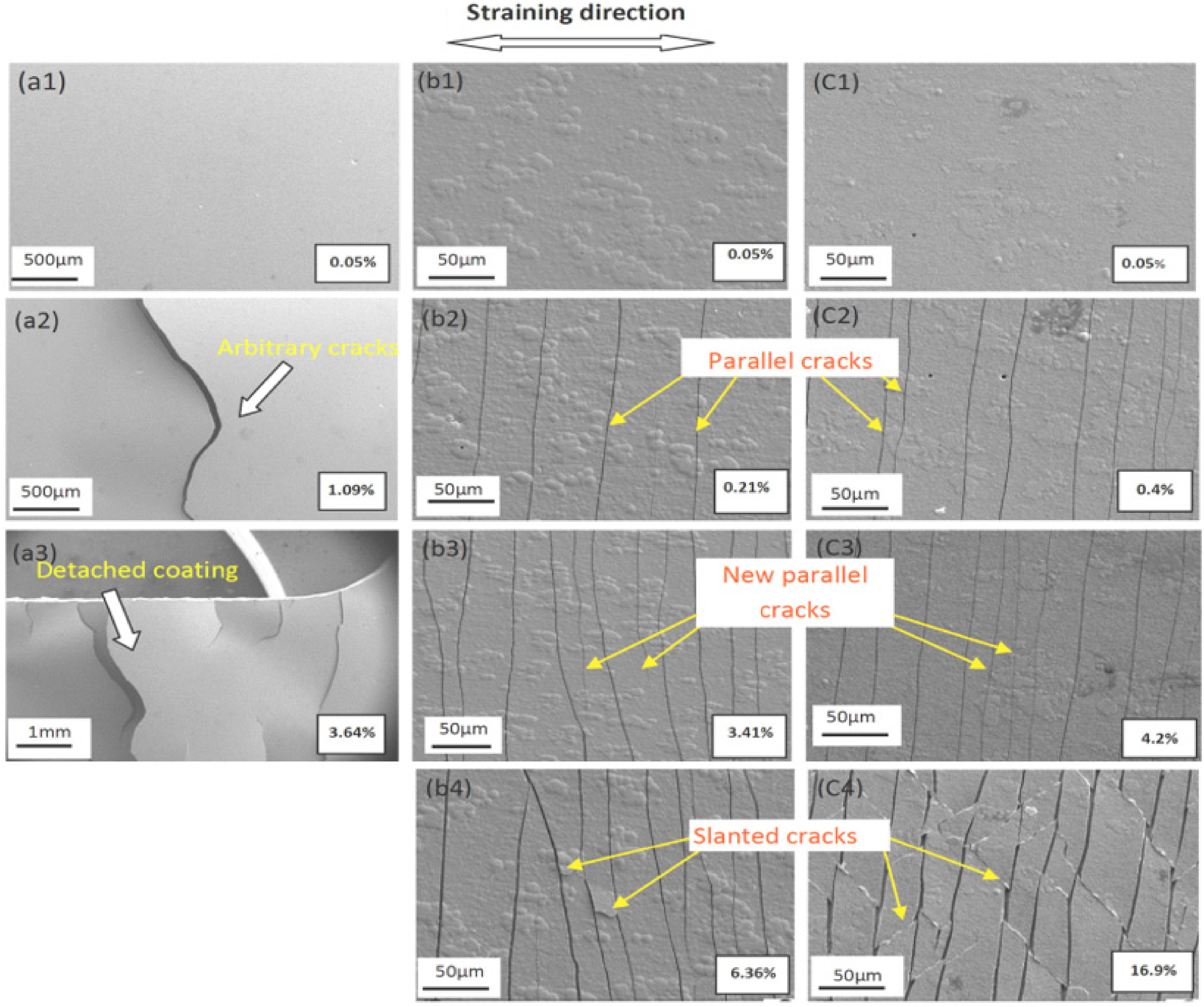
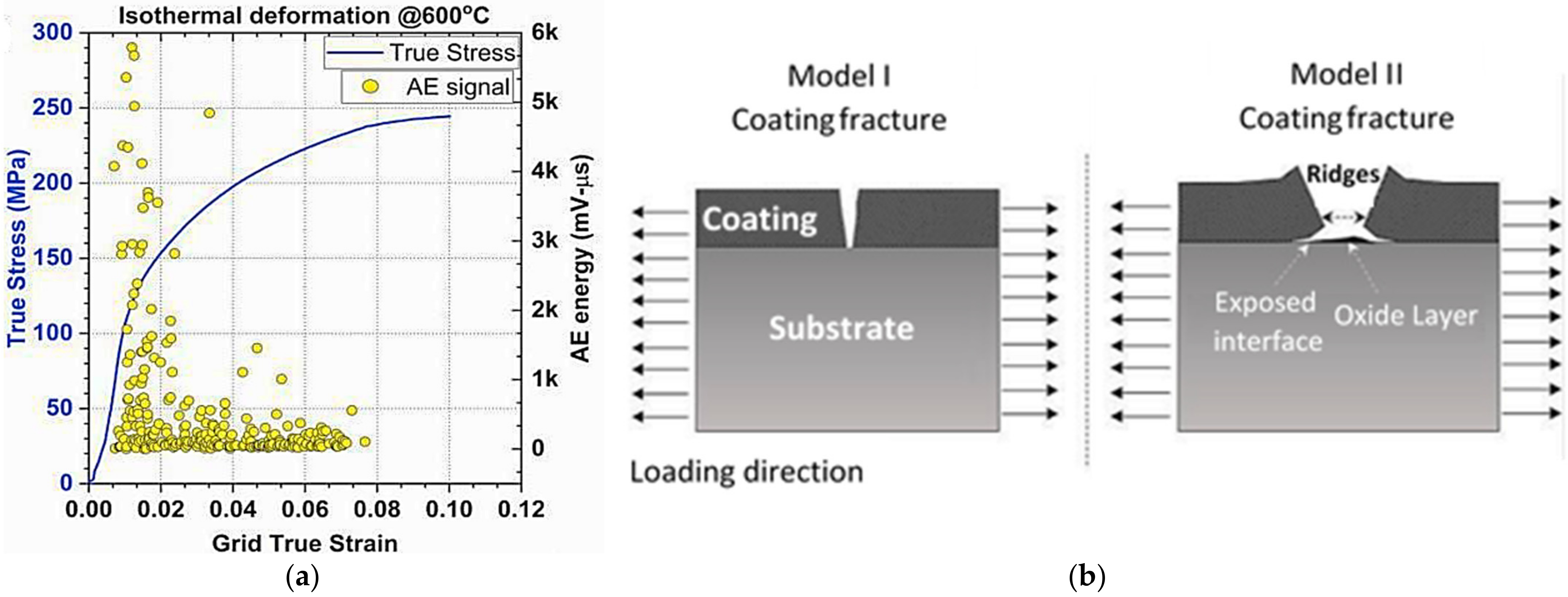
  6. Zaman, S.B.; Hazrati, J.; de Rooij, M.; van den Boogaard, T. Cracking Behavior of Coating during Hot Tensile Tests of AlSi-Coated Press Hardening Steel. Procedia Manuf. 2020, 47, 602–607. [Google Scholar] [CrossRef]
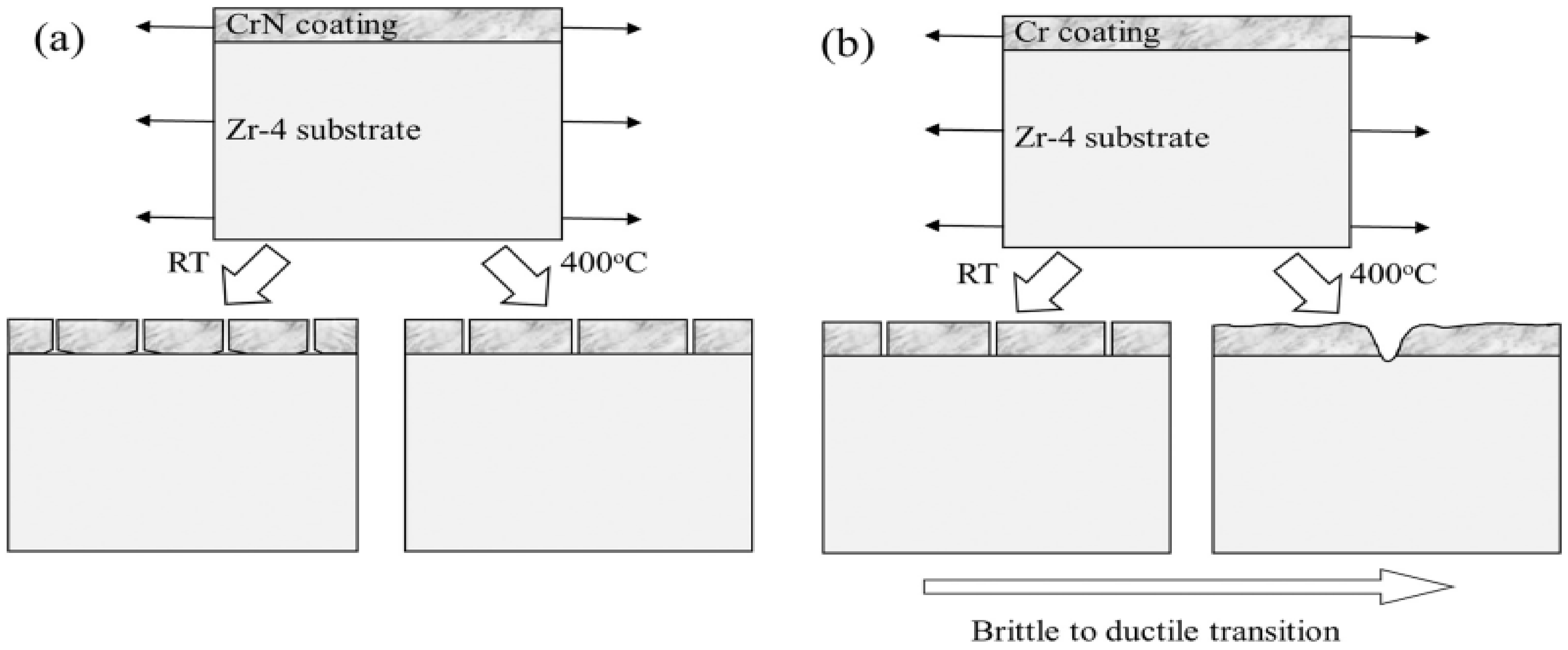
  7. Jiang, J.; Zhan, D.; Lv, J.; Ma, X.; He, X.; Wang, D.; Hu, Y.; Zhai, H.; Tu, J.; Zhang, W. Comparative study on the tensile cracking behavior of CrN and Cr coatings for accident-tolerant fuel claddings. Surf. Coat. Technol. 2021, 409, 126812. [Google Scholar] [CrossRef]
  8. Zhu, J.; Zhang, X.; Luo, H.; Sahraei, E. Investigation of the deformation mechanisms of lithium-ion battery components using in-situ micro tests. Appl. Energy 2018, 224, 251–266. [Google Scholar] [CrossRef]
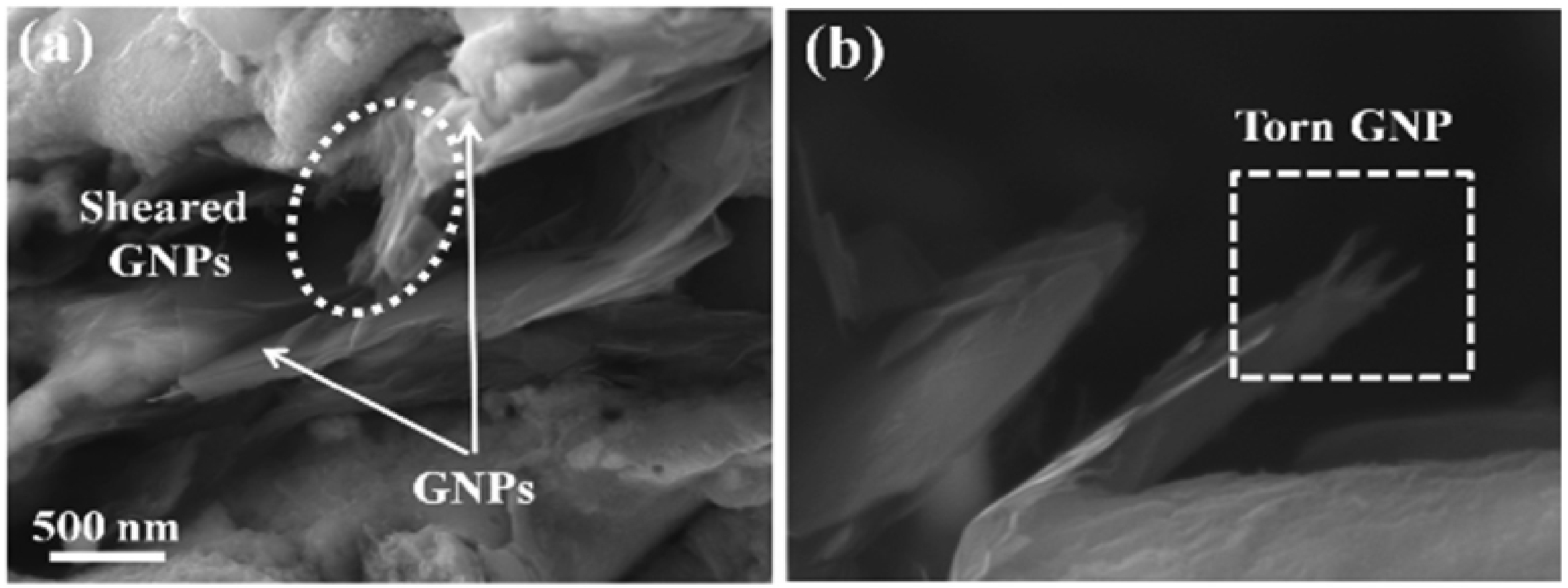
  9. Mukherjee, B.; Kumar, R.; Islam, A.; Rahman, O.S.A.; Keshri, A.K. Evaluation of strength-ductility combination by in-situ tensile testing of graphene nano platelets reinforced shroud plasma sprayed Nickel-Aluminium coating. J. Alloys Compd. 2018, 765, 1082–1089. [Google Scholar] [CrossRef]
  10. Xu, J.-S.; Zhang, X.-C.; Xuan, F.-Z.; Tian, F.-Q.; Wang, Z.-D.; Tu, S.-T. Tensile properties and fracture behavior of laser cladded WC/Ni composite coatings with different contents of WC particle studied by in-situ tensile testing. Mater. Sci. Eng. A 2013, 560, 744–751. [Google Scholar] [CrossRef]
  11. Greer, J.R.; De Hosson, J.T.M. Plasticity in small-sized metallic systems: Intrinsic versus extrinsic size effect. Prog. Mater. Sci. 2011, 56, 654–724. [Google Scholar] [CrossRef]
  12. Rehman, H.U.; Ahmed, F.; Schmid, C.; Schaufler, J.; Durst, K. Study on the deformation mechanics of hard brittle coatings on ductile substrates using in-situ tensile testing and cohesive zone FEM modeling. Surf. Coat. Technol. 2012, 207, 163–169. [Google Scholar] [CrossRef]
  13. Schaufler, J.; Schmid, C.; Durst, K.; Göken, M. Determination of the interfacial strength and fracture toughness of aC: H coatings by in-situ microcantilever bending. Thin Solid Films 2012, 522, 480–484. [Google Scholar] [CrossRef]
  14. Chen, Y.; Zhang, X.; Williams, C.J.; Brewster, G.; Xiao, P. Determination of fracture toughness of a platinum-modified nickel aluminide coating by micromechanical testing. Materialia 2021, 20, 101267. [Google Scholar] [CrossRef]
  15. Hirsch, P.B. Direct Observations of moving dislocations: Reflections on the thirtieth anniversary of the first recorded observations of moving dislocations by transmission electron microscopy. Mater. Sci. Eng. 1986, 84, 1–10. [Google Scholar] [CrossRef]
  16. Hirsch, P.B.; Horne, R.W.; Whelan, M.J. Direct observations of the arrangement and motion of dislocations in aluminium. Philos. Mag. 1956, 1, 677–684. [Google Scholar] [CrossRef]
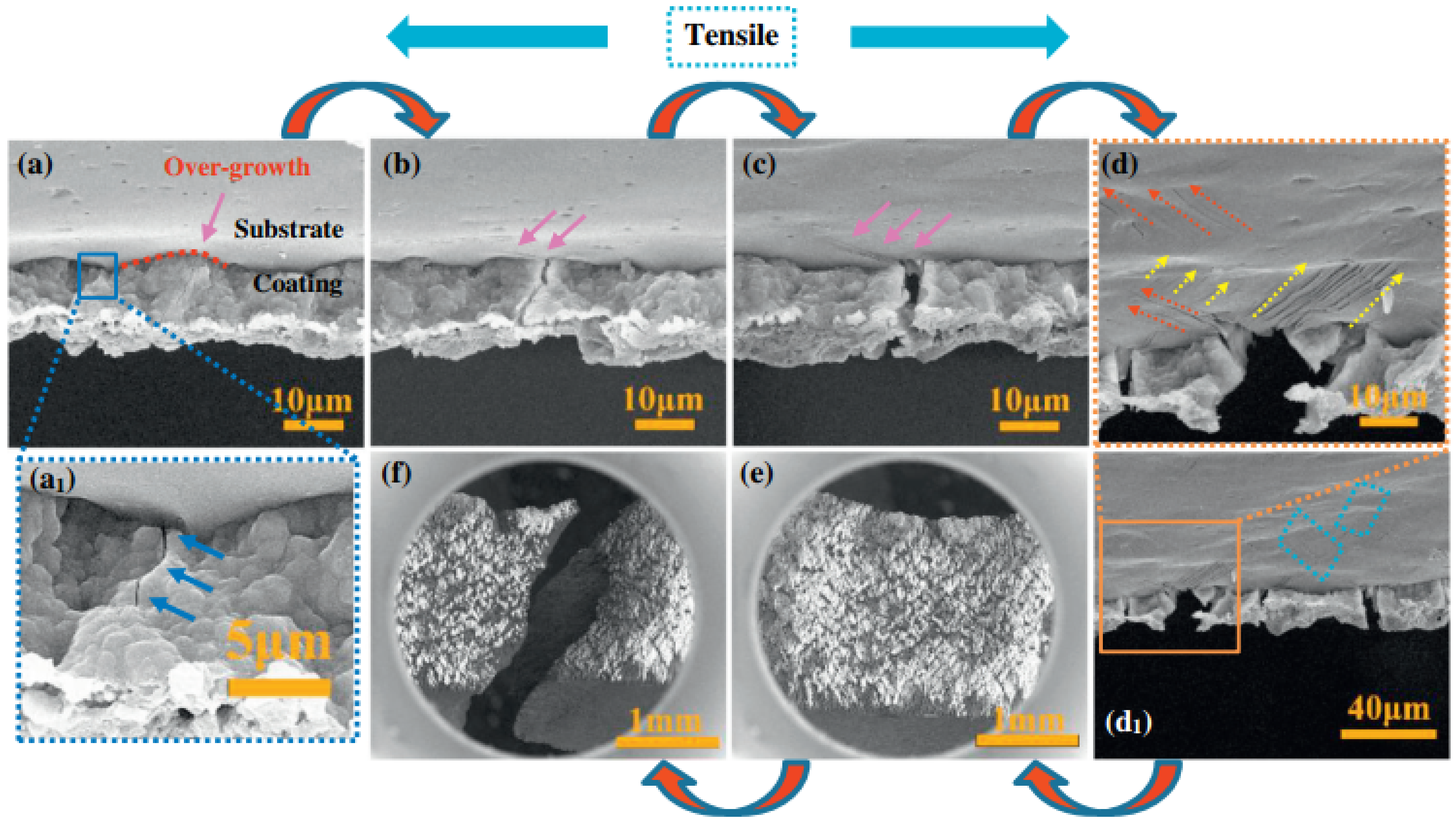
  17. Chen, Z.; Li, G.; Wu, Z.; Xia, Y. The crack propagating behavior of composite coatings prepared by PEO on aluminized steel during in situ tensile processing. Mater. Sci. Eng. A 2011, 528, 1409–1414. [Google Scholar] [CrossRef] [Green Version]
  18. Kiilakoski, J.; Musalek, R.; Lukac, F.; Koivuluoto, H.; Vuoristo, P. Evaluating the toughness of APS and HVOF-sprayed Al2O3-ZrO2-coatings by in-situ-and macroscopic bending. J. Eur. Ceram. Soc. 2018, 38, 1908–1918. [Google Scholar] [CrossRef]
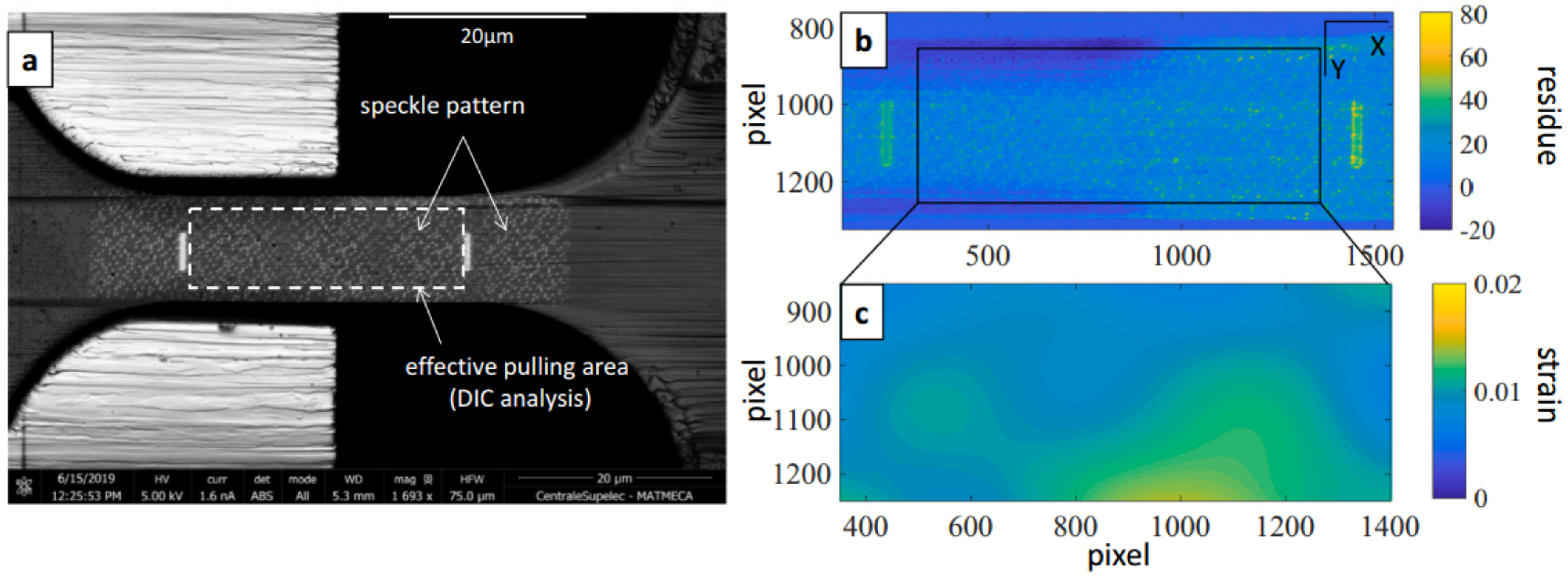
  19. Zhou, M.; Yao, W.B.; Yang, X.S.; Peng, Z.B.; Li, K.K.; Dai, C.Y.; Mao, W.G.; Zhou, Y.C.; Lu, C. In-situ and real-time tests on the damage evolution and fracture of thermal barrier coatings under tension: A coupled acoustic emission and digital image correlation method. Surf. Coat. Technol. 2014, 240, 40–47. [Google Scholar] [CrossRef]
  20. Rudolf, C.; Boesl, B.; Agarwal, A. In situ mechanical testing techniques for real-time materials deformation characterization. JOM 2016, 68, 136–142. [Google Scholar] [CrossRef]
  21. Singh, S.; Singh, H.; Chaudhary, S.; Buddu, R.K. Effect of substrate surface roughness on properties of cold-sprayed copper coatings on SS316L steel. Surf. Coat. Technol. 2020, 389, 125619. [Google Scholar] [CrossRef]
  22. Bouaziz, H.; Brinza, O.; Haddar, N.; Gasperini, M.; Feki, M. In-situ SEM study of crack initiation, propagation and interfacial debonding of Ni-P coating during tensile tests: Heat treatment effect. Mater. Charact. 2017, 123, 106–114. [Google Scholar] [CrossRef]
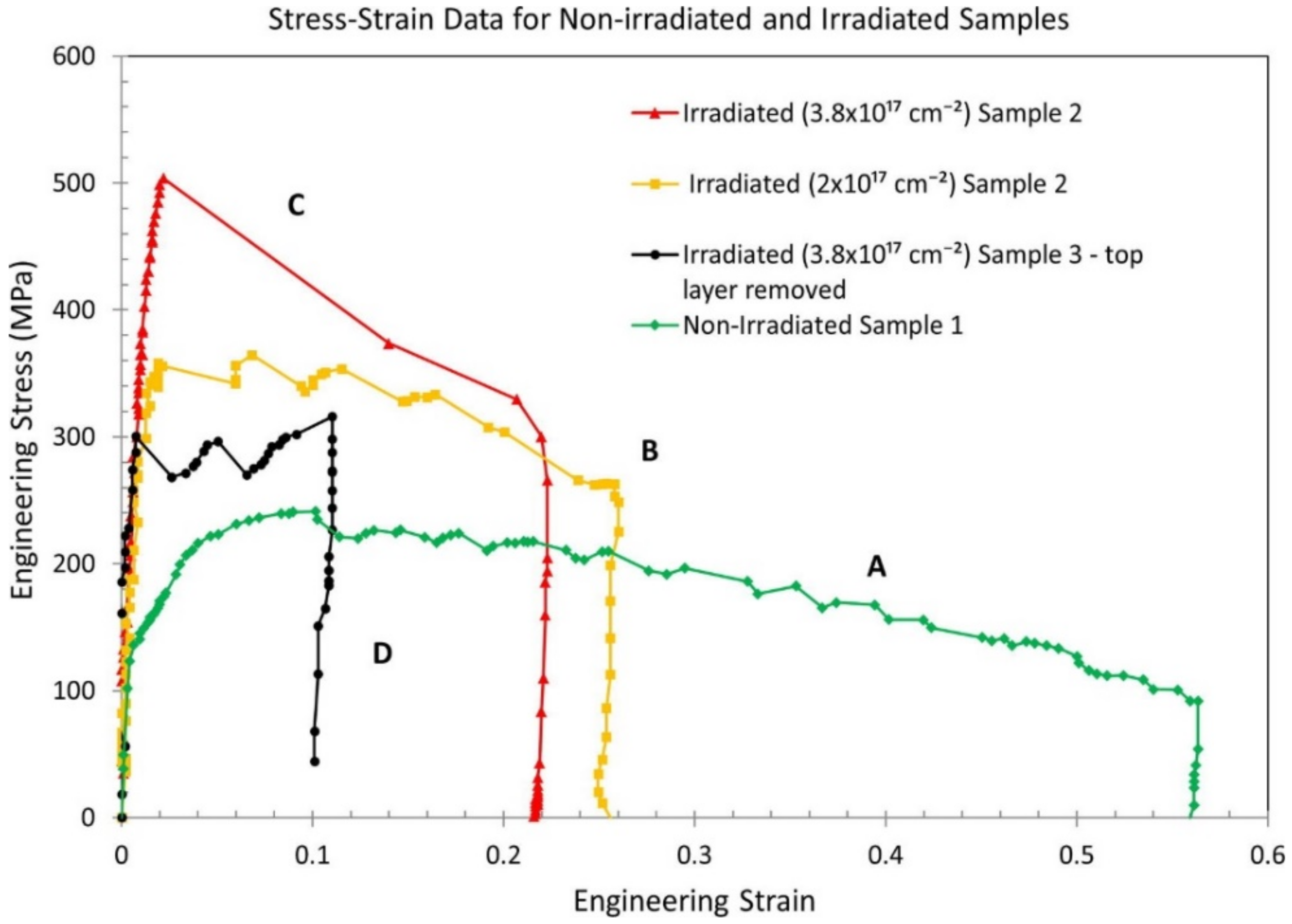
  23. Reichardt, A.; Ionescu, M.; Davis, J.; Edwards, L.; Harrison, R.P.; Hosemann, P.; Bhattacharyya, D. In situ micro tensile testing of He+2 ion irradiated and implanted single crystal nickel film. Acta Mater. 2015, 100, 147–154. [Google Scholar] [CrossRef] [Green Version]
  24. Mao, W.; Wang, Y.; Huang, H.; Zeng, L.; Wang, Y.; Lv, L.; Feng, B.; Zou, C.; Dai, C.; Tang, Q. In situ characterizations of mechanical behaviors of freestanding (Gd0.9Yb0.1)2Zr2O7 coatings by bending tests under different temperatures based on digital image correlation. J. Eur. Ceram. Soc. 2020, 40, 491–502. [Google Scholar] [CrossRef]
  25. Cai, X.; Xu, Y.; Zhao, N.; Zhong, L.; Zhao, Z.; Wang, J. Investigation of the adhesion strength and deformation behaviour of in situ fabricated NbC coatings by scratch testing. Surf. Coat. Technol. 2016, 299, 135–142. [Google Scholar] [CrossRef]
  26. Best, J.P.; Guillonneau, G.; Grop, S.; Taylor, A.A.; Frey, D.; Longchamp, Q.; Schär, T.; Morstein, M.; Breguet, J.-M.; Michler, J. High temperature impact testing of a thin hard coating using a novel high-frequency in situ micromechanical device. Surf. Coat. Technol. 2018, 333, 178–186. [Google Scholar] [CrossRef]
  27. Cao, H.; Bai, M.; Inkson, B.J.; Zhong, X.; De Hosson, J.T.M.; Pei, Y.; Xiao, P. Self-healing WS2 tribofilms: An in-situ appraisal of mechanisms. Scr. Mater. 2021, 204, 114124. [Google Scholar] [CrossRef]
  28. Rzepiejewska-Malyska, K.A.; Mook, W.M.; Parlinska-Wojtan, M.; Hejduk, J.; Michler, J. In situ scanning electron microscopy indentation studies on multilayer nitride films: Methodology and deformation mechanisms. J. Mater. Res. 2009, 24, 1208–1221. [Google Scholar] [CrossRef] [Green Version]
  29. Qu, Z.; Wei, K.; He, Q.; He, R.; Pei, Y.; Wang, S.; Fang, D. High temperature fracture toughness and residual stress in thermal barrier coatings evaluated by an in-situ indentation method. Ceram. Int. 2018, 44, 7926–7929. [Google Scholar] [CrossRef]
  30. Nautiyal, P.; Boesl, B.; Agarwal, A. In-Situ Mechanics of Materials; Springer: Berlin/Heidelberg, Germany, 2020. [Google Scholar]
  31. Gane, N.; Bowden, F.P. Microdeformation of solids. J. Appl. Phys. 1968, 39, 1432–1435. [Google Scholar] [CrossRef]
  32. Bangert, H.; Wagendristel, A. Ultralow-load hardness tester for use in a scanning electron microscope. Rev. Sci. Instrum. 1985, 56, 1568–1572. [Google Scholar] [CrossRef]
  33. Wang, C.L.; Lai, Y.H.; Huang, J.C.; Nieh, T.G. Creep of nanocrystalline nickel: A direct comparison between uniaxial and nanoindentation creep. Scr. Mater. 2010, 62, 175–178. [Google Scholar] [CrossRef]
  34. Nautiyal, P.; Jain, J.; Agarwal, A. A comparative study of indentation induced creep in pure magnesium and AZ61 alloy. Mater. Sci. Eng. A 2015, 630, 131–138. [Google Scholar] [CrossRef]
  35. Rabe, R.; Breguet, J.M.; Schwaller, P.; Stauss, S.; Haug, F.J.; Patscheider, J.; Michler, J. Observation of fracture and plastic deformation during indentation and scratching inside the scanning electron microscope. Thin Solid Films 2004, 469–470, 206–213. [Google Scholar] [CrossRef]
  36. Bakshi, S.R.; Lahiri, D.; Patel, R.R.; Agarwal, A. Nanoscratch behavior of carbon nanotube reinforced aluminum coatings. Thin Solid Films 2010, 518, 1703–1711. [Google Scholar] [CrossRef]
  37. Takeuchi, T. Load-Elongation Curves of Pure Body-Centred Cubic Metals at Low Temperatures. J. Phys. Soc. Jpn. 1973, 35, 1149–1160. [Google Scholar] [CrossRef]
  38. Sumino, K.; Sato, M. In-situ HVEM Observations of Dislocation Processes during High Temperature Deformation of Silicon Crystals. Krist. Tech. 1979, 14, 1343–1350. [Google Scholar] [CrossRef]
  39. Louchet, F.; Kubin, L.P.; Vesely, D. In situ deformation of b.c.c. crystals at low temperatures in a high-voltage electron microscope Dislocation mechanisms and strain-rate equation. Philos. Mag. A 1979, 39, 433–454. [Google Scholar] [CrossRef]
  40. Ohr, S.M. An electron microscope study of crack tip deformation and its impact on the dislocation theory of fracture. Mater. Sci. Eng. 1985, 72, 1–35. [Google Scholar] [CrossRef]
  41. Mindess, S.; Diamond, S. A preliminary SEM study of crack propagation in mortar. Cem. Concr. Res. 1980, 10, 509–519. [Google Scholar] [CrossRef]
  42. Sernicola, G.; Giovannini, T.; Patel, P.; Kermode, J.; Balint, D.S.; Britton, B.; Giuliani, F. In situ stable crack growth at the micron scale. Nat. Commun. 2017, 8, 108. [Google Scholar] [CrossRef] [PubMed]
  43. Zhang, C.; Boesl, B.; Silvestroni, L.; Sciti, D.; Agarwal, A. Deformation mechanism in graphene nanoplatelet reinforced tantalum carbide using high load in situ indentation. Mater. Sci. Eng. A 2016, 674, 270–275. [Google Scholar] [CrossRef]
  44. Fazel, Z.A.; Elmkhah, H.; Fattah-Alhosseini, A.; Babaei, K.; Meghdari, M. Comparing electrochemical behavior of applied CrN/TiN nanoscale multilayer and TiN single-layer coatings deposited by CAE-PVD method. J. Asian Ceram. Soc. 2020, 8, 510–518. [Google Scholar] [CrossRef] [Green Version]
  45. Icriverzi, M.; Rusen, L.; Brajnicov, S.; Bonciu, A.; Dinescu, M.; Cimpean, A.; Evans, R.W.; Dinca, V.; Roseanu, A. Macrophage in vitro response on hybrid coatings obtained by matrix assisted pulsed laser evaporation. Coatings 2019, 9, 236. [Google Scholar] [CrossRef] [Green Version]
  46. Zhu, Y.; Xu, F.; Qin, Q.; Fung, W.Y.; Lu, W. Mechanical properties of vapor–liquid–solid synthesized silicon nanowires. Nano Lett. 2009, 9, 3934–3939. [Google Scholar] [CrossRef] [Green Version]
  47. Zhu, Y.; Qin, Q.; Gu, Y.; Wang, Z. Friction and shear strength at the nanowire–substrate interfaces. Nanoscale Res. Lett. 2010, 5, 291–295. [Google Scholar] [CrossRef] [Green Version]
  48. Joshi, M.; Bhattacharyya, A.; Ali, S.W. Characterization Techniques for Nanotechnology Applications in Textiles. 2008. Available online: http://nopr.niscair.res.in/handle/123456789/2019 (accessed on 1 December 2021).
  49. Suzuki, E. High-resolution scanning electron microscopy of immunogold-labelled cells by the use of thin plasma coating of osmium. J. Microsc. 2002, 208, 153–157. [Google Scholar] [CrossRef]
  50. Goldstein, J.I.; Newbury, D.E.; Michael, J.R.; Ritchie, N.W.M.; Scott, J.H.J.; Joy, D.C. Scanning Electron Microscopy and X-ray Microanalysis; Springer: Berlin/Heidelberg, Germany, 2017; ISBN 1493966766. [Google Scholar]
  51. Legros, M. In situ mechanical TEM: Seeing and measuring under stress with electrons. C. R. Phys. 2014, 15, 224–240. [Google Scholar] [CrossRef]
  52. Voisin, T.; Grapes, M.D.; Zhang, Y.; Lorenzo, N.J.; Ligda, J.P.; Schuster, B.E.; Santala, M.K.; Li, T.; Campbell, G.H.; Weihs, T.P. DTEM in situ mechanical testing: Defects motion at high strain rates. In Dynamic Behavior of Materials; Springer: Berlin/Heidelberg, Germany, 2017; Volume 1, pp. 209–213. [Google Scholar]
  53. Erni, R.; Rossell, M.D.; Kisielowski, C.; Dahmen, U. Atomic-resolution imaging with a sub-50-pm electron probe. Phys. Rev. Lett. 2009, 102, 96101. [Google Scholar] [CrossRef] [Green Version]
  54. O’Keefe, M.A.; Allard, L.F. Sub-Angstrom Electron Microscopy for Sub-Angstrom Nano-Metrology; Lawrence Berkeley National Lab. (LBNL): Berkeley, CA, USA, 2004. [Google Scholar]
  55. Nishinoiri, S.; Enoki, M.; Tomita, K. In situ monitoring of microfracture during plasma spray coating by laser AE technique. Sci. Technol. Adv. Mater. 2003, 4, 623. [Google Scholar] [CrossRef]
  56. Ray, A.K.; Roy, N.; Kar, A.; Ray, A.K.; Bose, S.C.; Das, G.; Sahu, J.K.; Das, D.K.; Venkataraman, B.; Joshi, S.V. Mechanical property and characterization of a NiCoCrAlY type metallic bond coat used in turbine blade. Mater. Sci. Eng. A 2009, 505, 96–104. [Google Scholar] [CrossRef]
  57. Wu, D.J.; Mao, W.G.; Zhou, Y.C.; Lu, C. Digital image correlation approach to cracking and decohesion in a brittle coating/ductile substrate system. Appl. Surf. Sci. 2011, 257, 6040–6043. [Google Scholar] [CrossRef] [Green Version]
  58. Pfeiffer, C.; Affeldt, E.; Göken, M. Miniaturized bend tests on partially stabilized EB-PVD ZrO2 thermal barrier coatings. Surf. Coat. Technol. 2011, 205, 3245–3250. [Google Scholar] [CrossRef]
  59. Jiang, J.; Zhai, H.; Du, M.; Wang, D.; Pei, X.; Ma, X.; Wang, B. Temperature-dependent deformation and cracking behavior in Cr coating for accident tolerant fuel cladding: An in situ SEM study. Surf. Coat. Technol. 2021, 427, 127815. [Google Scholar] [CrossRef]
  60. da Costa, M.V.T.; Bolinsson, J.; Fayet, P.; Gamstedt, E.K. Transverse ridge cracking in tensile fragmentation tests of thin brittle coatings on polymer substrates. Surf. Coat. Technol. 2020, 382, 125025. [Google Scholar] [CrossRef]
  61. Völker, B.; Du, C.; Fager, H.; Rueß, H.; Soler, R.; Kirchlechner, C.; Dehm, G.; Schneider, J.M. How tensile tests allow a screening of the fracture toughness of hard coatings. Surf. Coat. Technol. 2020, 390, 125645. [Google Scholar] [CrossRef]
  62. Mao, W.G.; Chen, Y.Y.; Wang, Y.J.; Zhou, M.; Yang, H.Y.; Wang, Z.; Dai, C.Y.; Chen, X.; Fang, D.N. A multilayer structure shear lag model applied in the tensile fracture characteristics of supersonic plasma sprayed thermal barrier coating systems based on digital image correlation. Surf. Coat. Technol. 2018, 350, 211–226. [Google Scholar] [CrossRef]
  63. Singh, S.; Chaudhary, S.; Singh, H. Effect of electroplated interlayers on properties of cold-sprayed copper coatings on SS316L steel. Surf. Coat. Technol. 2019, 375, 54–65. [Google Scholar] [CrossRef]
  64. da Costa, M.V.T.; Bolinsson, J.; Neagu, R.C.; Fayet, P.; Gamstedt, E.K. Experimental assessment of micromechanical models for fragmentation analysis of thin metal oxide coatings on polymer films under uniaxial tensile deformation. Surf. Coat. Technol. 2019, 370, 374–383. [Google Scholar] [CrossRef]
  65. Rochat, G.; Leterrier, Y.; Fayet, P.; Månson, J.-A. Mechanical analysis of ultrathin oxide coatings on polymer substrates in situ in a scanning electron microscope. Thin Solid Films 2003, 437, 204–210. [Google Scholar] [CrossRef]
  66. Chen, B.F.; Hwang, J.; Yu, G.P.; Huang, J.H. In situ observation of the cracking behavior of TiN coating on 304 stainless steel subjected to tensile strain. Thin Solid Films 1999, 352, 173–178. [Google Scholar] [CrossRef]
  67. Ahmadi, M.; Salgın, B.; Kooi, B.J.; Pei, Y. Cracking behavior and formability of Zn-Al-Mg coatings: Understanding the influence of steel substrates. Mater. Des. 2021, 212, 110215. [Google Scholar] [CrossRef]
  68. Yang, L.; Zhou, Y.C.; Mao, W.G.; Lu, C. Real-time acoustic emission testing based on wavelet transform for the failure process of thermal barrier coatings. Appl. Phys. Lett. 2008, 93, 231906. [Google Scholar] [CrossRef]
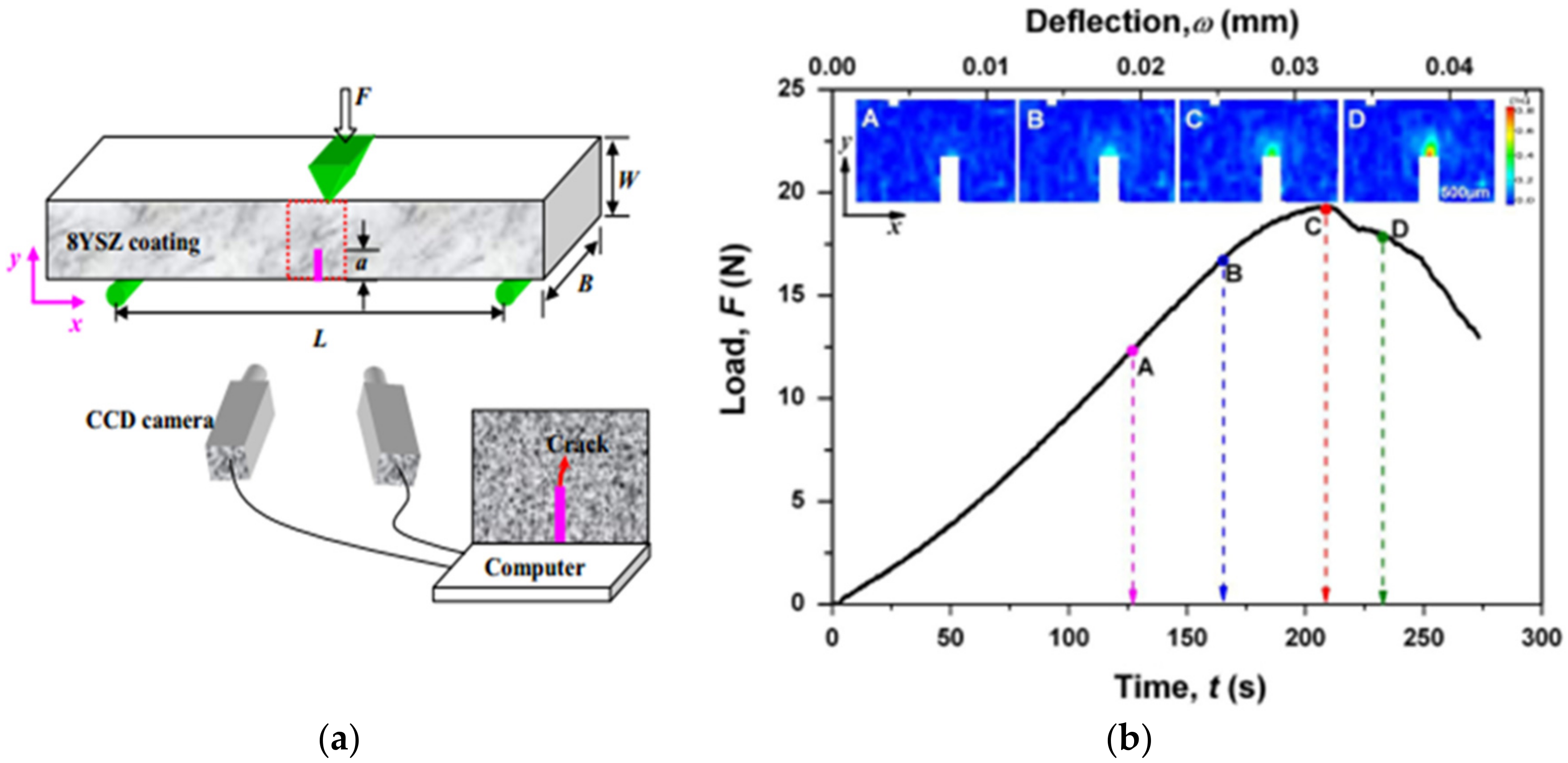
  69. Patibanda, S.; Nagda, V.J.; Kalra, J.; Sivakumar, G.; Abrahams, R.; Jonnalagadda, K.N. Mechanical behavior of freestanding 8YSZ thin films under tensile and bending loads. Surf. Coat. Technol. 2020, 393, 125771. [Google Scholar] [CrossRef]
  70. Qian, L.; Zhu, S.; Kagawa, Y.; Kubo, T. Tensile damage evolution behavior in plasma-sprayed thermal barrier coating system. Surf. Coat. Technol. 2003, 173, 178–184. [Google Scholar] [CrossRef]
  71. Jiang, J.; Zhai, H.; Gong, P.; Zhang, W.; He, X.; Ma, X.; Wang, B. In-situ study on the tensile behavior of Cr-coated zircaloy for accident tolerant fuel claddings. Surf. Coat. Technol. 2020, 394, 125747. [Google Scholar] [CrossRef]
  72. Ma, X.; Zhai, H.; Meng, F.; Jiang, J.; He, X.; Hu, Y.; Zhang, W.; Tu, J.; Wei, D.; Wang, B. Benefit or harm of accident tolerant coatings on the low-cycle fatigue properties of Zr-4 cladding alloy: In-situ studies at 400 °C. J. Nucl. Mater. 2021, 545, 152651. [Google Scholar] [CrossRef]
  73. bin Zaman, S.; Hazrati, J.; de Rooij, M.; Matthews, D.; van den Boogaard, T. Investigating AlSi coating fracture at high temperatures using acoustic emission sensors. Surf. Coat. Technol. 2021, 423, 127587. [Google Scholar] [CrossRef]
  74. Appleby, M.P.; Zhu, D.; Morscher, G.N. Mechanical properties and real-time damage evaluations of environmental barrier coated SiC/SiC CMCs subjected to tensile loading under thermal gradients. Surf. Coat. Technol. 2015, 284, 318–326. [Google Scholar] [CrossRef] [Green Version]
  75. Arnaud, P.; Heripre, E.; Douit, F.; Aubin, V.; Fouvry, S.; Guiheux, R.; Branger, V.; Michel, G. Micromechanical tensile test investigation to identify elastic and toughness properties of thin nitride compound layers. Surf. Coat. Technol. 2021, 421, 127303. [Google Scholar] [CrossRef]
  76. Chen, Y.; Li, C.; Zhao, X.; Xiao, P. Measurements and understanding of the stiffness of an air plasma sprayed thermal barrier coating. Surf. Coat. Technol. 2020, 394, 125678. [Google Scholar] [CrossRef]
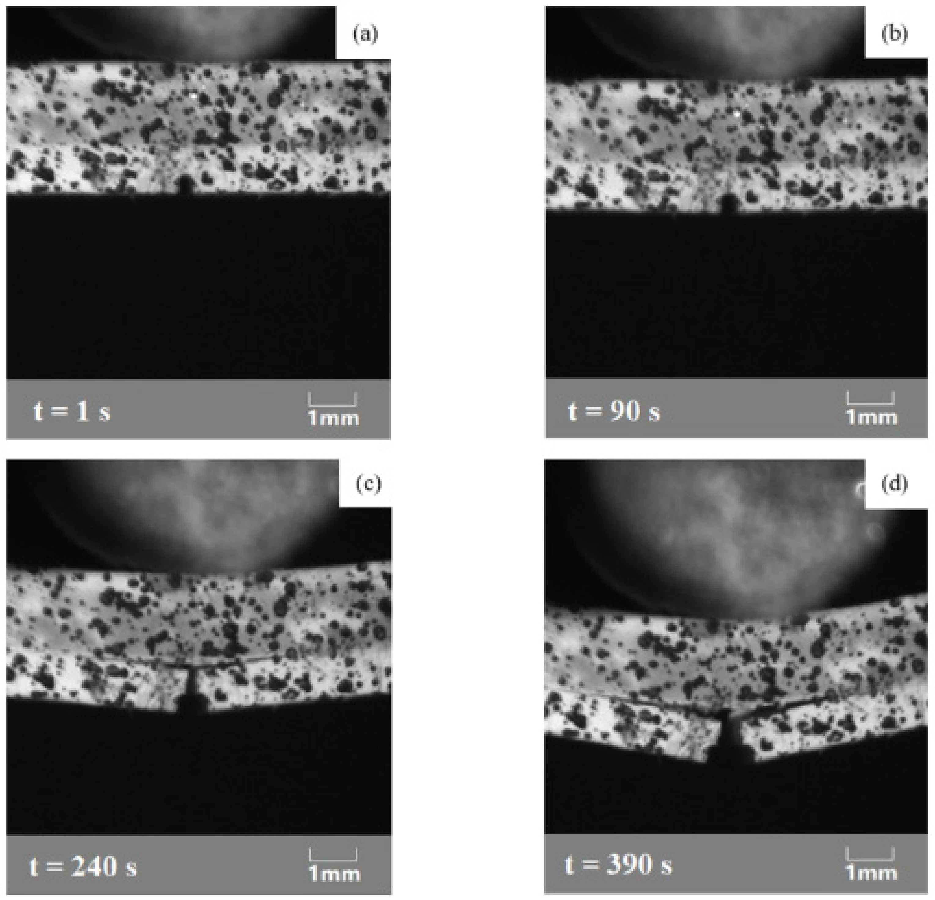
  77. Zhu, W.; Wu, Q.; Yang, L.; Zhou, Y.C. In situ characterization of high temperature elastic modulus and fracture toughness in air plasma sprayed thermal barrier coatings under bending by using digital image correlation. Ceram. Int. 2020, 46, 18526–18533. [Google Scholar] [CrossRef]
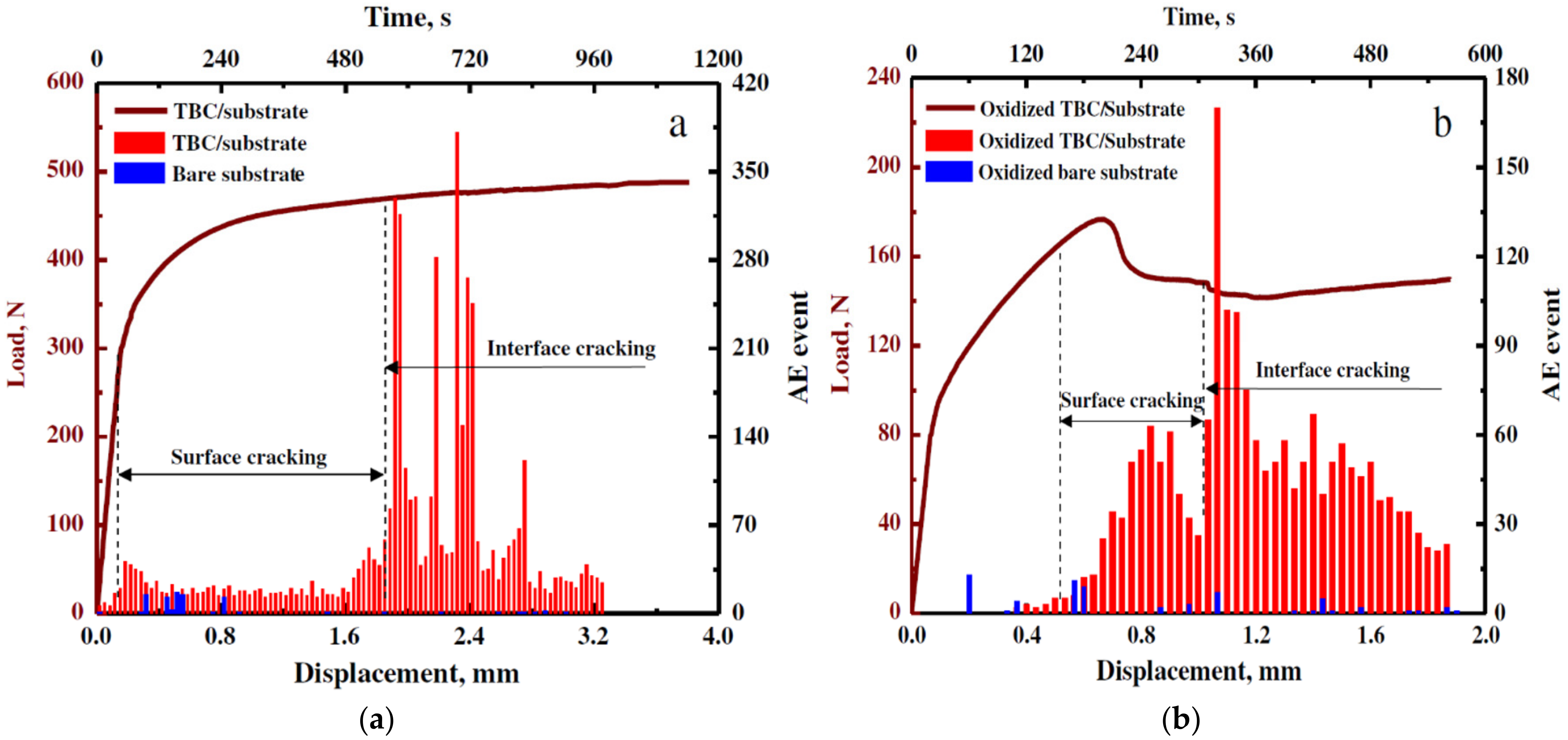
  78. Yang, L.; Zhong, Z.C.; You, J.; Zhang, Q.M.; Zhou, Y.C.; Tang, W.Z. Acoustic emission evaluation of fracture characteristics in thermal barrier coatings under bending. Surf. Coat. Technol. 2013, 232, 710–718. [Google Scholar] [CrossRef]
  79. Jiang, P.; Fan, X.; Sun, Y.; Li, D.; Wang, T. Bending-driven failure mechanism and modelling of double-ceramic-layer thermal barrier coating system. Int. J. Solids Struct. 2018, 130, 11–20. [Google Scholar] [CrossRef]
  80. Li, X.N.; Liang, L.H.; Xie, J.J.; Chen, L.; Wei, Y.G. Thickness-dependent fracture characteristics of ceramic coatings bonded on the alloy substrates. Surf. Coat. Technol. 2014, 258, 1039–1047. [Google Scholar] [CrossRef]
  81. Martins, J.P.; Yu, H.; Chen, Y.; Brewster, G.; McIntyre, R.; Xiao, P. Effect of bond coat topography on the fracture mechanics and lifetime of air-plasma sprayed thermal barrier coatings. Surf. Coat. Technol. 2021, 421, 127447. [Google Scholar] [CrossRef]
  82. Planques, P.; Vidal, V.; Lours, P.; Proton, V.; Crabos, F.; Huez, J.; Viguier, B. Characterization of the mechanical properties of thermal barrier coatings by 3 points bending tests and modified small punch tests. Surf. Coat. Technol. 2017, 332, 40–46. [Google Scholar] [CrossRef] [Green Version]
  83. Wan, J.; Zhou, M.; Yang, X.S.; Dai, C.Y.; Zhang, Y.; Mao, W.G.; Lu, C. Fracture characteristics of freestanding 8 wt% Y2O3–ZrO2 coatings by single edge notched beam and Vickers indentation tests. Mater. Sci. Eng. A 2013, 581, 140–144. [Google Scholar] [CrossRef] [Green Version]
  84. Mušálek, R.; Kovářík, O.; Matějíček, J. In-situ observation of crack propagation in thermally sprayed coatings. Surf. Coat. Technol. 2010, 205, 1807–1811. [Google Scholar] [CrossRef]
  85. Liu, H.T.; Yang, L.W.; Sun, X.; Cheng, H.F.; Wang, C.Y.; Mao, W.G.; Molina-Aldareguia, J.M. Enhancing the fracture resistance of carbon fiber reinforced SiC matrix composites by interface modification through a simple fiber heat-treatment process. Carbon 2016, 109, 435–443. [Google Scholar] [CrossRef]
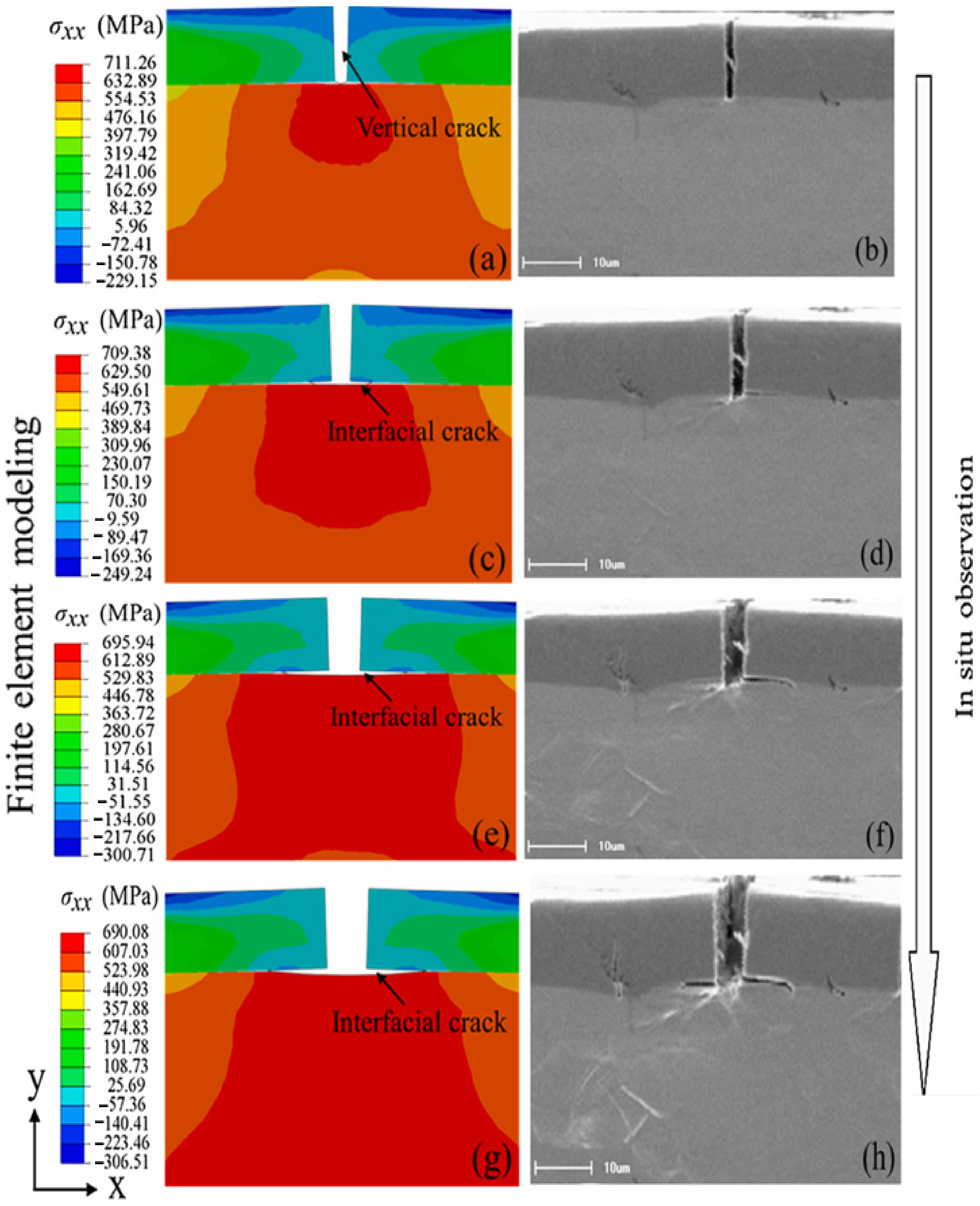
  86. Jiang, J.; Yuan, M.; Du, M.; Ma, X. On the crack propagation and fracture properties of Cr-coated Zr-4 alloys for accident-tolerant fuel cladding: In situ three-point bending test and cohesive zone modeling. Surf. Coat. Technol. 2021, 427, 127810. [Google Scholar] [CrossRef]
  87. Jiang, J.; Du, M.; Pan, Z.; Yuan, M.; Ma, X.; Wang, B. Effects of oxidation and inter-diffusion on the fracture mechanisms of Cr-coated Zry-4 alloys: An in situ three-point bending study. Mater. Des. 2021, 212, 110168. [Google Scholar] [CrossRef]
  88. Liang, L.H.; Li, X.N.; Liu, H.Y.; Wang, Y.B.; Wei, Y.G. Power-law characteristics of damage and failure of ceramic coating systems under three-point bending. Surf. Coat. Technol. 2016, 285, 113–119. [Google Scholar] [CrossRef] [Green Version]
  89. Grigore, E.; Ruset, C.; Short, K.; Hoeft, D.; Dong, H.; Li, X.Y.; Bell, T. In situ investigation of the internal stress within the nc-Ti2N/nc-TiN nanocomposite coatings produced by a combined magnetron sputtering and ion implantation method. Surf. Coat. Technol. 2005, 200, 744–747. [Google Scholar] [CrossRef]
  90. Wang, W.; Zhang, C.; Zhang, Z.-W.; Li, Y.-C.; Yasir, M.; Wang, H.-T.; Liu, L. Toughening Fe-based amorphous coatings by reinforcement of amorphous carbon. Sci. Rep. 2017, 7, 4084. [Google Scholar] [CrossRef] [Green Version]
  91. Chen, Y.; Zhang, X.; Zhao, X.; Markocsan, N.; Nylén, P.; Xiao, P. Measurements of elastic modulus and fracture toughness of an air plasma sprayed thermal barrier coating using micro-cantilever bending. Surf. Coat. Technol. 2019, 374, 12–20. [Google Scholar] [CrossRef] [Green Version]
  92. Armstrong, D.E.J.; Haseeb, A.; Roberts, S.G.; Wilkinson, A.J.; Bade, K. Nanoindentation and micro-mechanical fracture toughness of electrodeposited nanocrystalline Ni–W alloy films. Thin Solid Films 2012, 520, 4369–4372. [Google Scholar] [CrossRef]
  93. Di Maio, D.; Roberts, S.G. Measuring fracture toughness of coatings using focused-ion-beam-machined microbeams. J. Mater. Res. 2005, 20, 299–302. [Google Scholar] [CrossRef]
  94. Matoy, K.; Schönherr, H.; Detzel, T.; Schöberl, T.; Pippan, R.; Motz, C.; Dehm, G. A comparative micro-cantilever study of the mechanical behavior of silicon based passivation films. Thin Solid Films 2009, 518, 247–256. [Google Scholar] [CrossRef]
  95. Matoy, K.; Detzel, T.; Müller, M.; Motz, C.; Dehm, G. Interface fracture properties of thin films studied by using the micro-cantilever deflection technique. Surf. Coat. Technol. 2009, 204, 878–881. [Google Scholar] [CrossRef]
  96. Riedl, A.; Daniel, R.; Stefenelli, M.; Schöberl, T.; Kolednik, O.; Mitterer, C.; Keckes, J. A novel approach for determining fracture toughness of hard coatings on the micrometer scale. Scr. Mater. 2012, 67, 708–711. [Google Scholar] [CrossRef]
  97. Chen, Y.; Xiao, P. Micromechanical testing of a thermally grown oxide on a MCrAlY coating. Surf. Coat. Technol. 2021, 419, 127300. [Google Scholar] [CrossRef]
  98. Liu, S.; Wheeler, J.M.; Howie, P.R.; Zeng, X.T.; Michler, J.; Clegg, W.J. Measuring the fracture resistance of hard coatings. Appl. Phys. Lett. 2013, 102, 171907. [Google Scholar] [CrossRef] [Green Version]
  99. Gruber, D.P.; Zalesak, J.; Todt, J.; Tkadletz, M.; Sartory, B.; Suuronen, J.-P.; Ziegelwanger, T.; Czettl, C.; Mitterer, C.; Keckes, J. Surface oxidation of nanocrystalline CVD TiB2 hard coatings revealed by cross-sectional nano-analytics and in-situ micro-cantilever testing. Surf. Coat. Technol. 2020, 399, 126181. [Google Scholar] [CrossRef]
  100. Mondal, K.; Nuñez, L., III; Downey, C.M.; van Rooyen, I.J. Thermal Barrier Coatings Overview: Design, Manufacturing, and Applications in High-Temperature Industries. Ind. Eng. Chem. Res. 2021, 60, 6061–6077. [Google Scholar] [CrossRef]
Figure 1. Schematic representation of the key tools and techniques utilized for the in situ characterization of materials at different length and force measurement scales.
Coatings 12 00299 g001
Figure 2. Crack patterns observed by SEM at the composite coating surface with (a) 4.10 vol% and (b) 13.95 vol% WC particles at the time of the test samples about to be broken [10].
Coatings 12 00299 g002
Figure 3. The initiation and propagation of crack at the composite coating surface with 6.20 vol% WC at various strain values: (a,b) 0.21% and (c) 0.76% [10].
Coatings 12 00299 g003
Figure 4. (a,b) FE-SEM image of high magnification revealing GNP after in situ tensile experimentation [9].
Coatings 12 00299 g004
Figure 5. Cracking patterns detected by SEM in electroless Ni-P coatings by straining: (a) the spallation of the as-deposited coatings at a small strain level and (b,c) parallel and slanted cracks formed for the heat-treated samples at 400 and 600 °C, respectively [22].
Coatings 12 00299 g005
Figure 6. Details of progressive tensile test in the coating/substrate during loading on the cross-section of a PEO-coated sample: (a) over-growth regions at the coating/substrate interface, (b,c) the crack propagation process, (d) further crack opening and propagation inside the substrate, (e,f) fracture occurrence [1].
Coatings 12 00299 g006
Figure 7. The crack accumulation observed by SEM at 0.05, 0.15, and 0.3 tensile strain for TiO2 coating [64].
Coatings 12 00299 g007
Figure 8. Schematics illustrating the deformation and fracture process of an (a) anode and (b) cathode [8].
Coatings 12 00299 g008
Figure 9. Development of the strain fields at the coating cross-section side under tensile experiments, where insets (a1d1) denote the change of εxx and insets (a2d2) show the variation of εzz [19].
Coatings 12 00299 g009
Figure 10. Schematic representation of the fracture response of the coated Zr-4 alloys under tension at room temperature (RT) and 400 °C: (a) The CrN-coated specimen and (b) the Cr-coated specimen [7].
Coatings 12 00299 g010
Figure 11. (a) Determined stress–strain curve and AE activity of AlSi-coated PHS under tensile deformation at 600 °C; (b) schematic representing fracture types of coating mode I (opening) and mode II (interfacial) [6].
Coatings 12 00299 g011
Figure 12. SEM image of unirradiated tensile sample (a) prior to testing and (b) after testing, exhibiting ≈56% plastic elongation; irradiated tensile sample (c) post-tensile test (top surface) showing almost brittle fracture, (d) fracture surface of specimen showing slip steps stopping a micron below top surface, with the marked line showing the limit of propagation of the slip lines [23].
Coatings 12 00299 g012
Figure 13. Engineering stress–strain data of one specimen from each irradiation condition [23].
Coatings 12 00299 g013
Figure 14. (a) The DIC analysis system; (b) the residue of the correlation (in % of grey level); (c) the determined strain field in the tensile direction [75].
Coatings 12 00299 g014
Figure 15. Fracture evolution for the tensile specimen containing HEA phase and (Ni, Co) Ti2 compounds [4].
Coatings 12 00299 g015
Figure 16. Load and AE event for the (a) as-sprayed and (b) pre-oxidized bare substrate and TBC/substrate [78].
Coatings 12 00299 g016
Figure 17. The crack initiation and propagation process detected at the room temperature (30 °C): (a) Initial state; (b) the initiation of surface crack; (c) the initiation of interfacial crack between TC and BC; and (d) the propagation of interfacial crack [77].
Coatings 12 00299 g017
Figure 18. (a) Schematic showing SENB test with the aid of the DIC system, (b) loading–deflection–time data of 8YSZ specimens during SENB. Different strain fields (insets A, B, C, and D) showing the evolution of strain with the increase in bending loads [83].
Coatings 12 00299 g018
Figure 19. Simulation and SEM results of interfacial crack evolution at ε of (a,b) 2.50%, (c,d) 4.25%, (e,f) 7.02%, (g,h) 10.13% [86].
Coatings 12 00299 g019
Figure 20. Fracture progression during in situ three-point bending of APS (a) F&C, (b) A&S; and HVOF (c) F&C, (d) A&S coatings. Displacement of the central support 0.3 mm (left) and 0.5 mm (right). Cracking direction and propagation are represented by the yellow arrows [18].
Coatings 12 00299 g020
Figure 21. (a) Micro-cantilever beam fabricated by FIB for the measurement of the interfacial fracture strength. (b) Notched bulk a-C:H cantilever for the measurement of the fracture toughness of a-C:H [13].
Coatings 12 00299 g021
Figure 22. Cross-sectional microstructure of cantilevers from (a) surface zone, (b) middle zone, and (c) interdiffusion zone representing the variation in precipitate content and size between the three zones [14].
Coatings 12 00299 g022
Figure 23. The load–displacement data of cantilevers in the surface zone, the middle zone, and the interdiffusion zone [14].
Coatings 12 00299 g023
Figure 24. Cracking in micro DCBs made from (a) CrN coating and (b) CrAlN/Si3N4 coating [98].
Coatings 12 00299 g024
Table 1. Summary of the current research work.
A Review on In Situ Mechanical Testing of Coatings
Monitoring TechniquesSEMTEMDICAE
Mechanical testingTensileBending
MethodsMacro-tensile
(RT and HT)
Micro/Nano-tensile
(FIB samples)
Macro-bending
(3-point or 4 point)
Micro-bending
(FIB samples)
Covered Subjects Deformation and fracture of coatingsMechanical characteristics evolutionHeat treatment & temperature dependance effectsMaterial composition & structureThickness variation & Deposition method
Coatings studiedThermal barrier coatingComposite coatings
(GNPs/NiAl)
Metal/alloy coatings
(Cr on Zr)
Hard ceramic coating
(CrN, TiN)
Current Limits
-
The current maximum testing temperature of coatings inside SEM is about 600 °C.
-
TEM technique requires electron transparent and ultrathin samples.
-
DIC testing temperature up to 1600 °C but no insight on the interior of material.
-
AE events require complex analysis & affected by acoustic noise.
Future perspectives
-
Increase the SEM testing temperature limits to study TBCs and EBCs.
-
Testing coatings and thin films behavior under different stress states using notched samples.
-
Investigation on the promising high entropy alloy as coating material.
-
More incorporation of FEA in thermomechanical & fracture analysis of coatings.
Publisher’s Note: MDPI stays neutral with regard to jurisdictional claims in published maps and institutional affiliations.

