
Thermal Characterization of Coolant Maxwell Type Nanofluid Flowing in Parabolic Trough Solar Collector (PTSC) Used Inside Solar Powered Ship Application

 , , ,
, , , 
Abstract
:1. Introduction
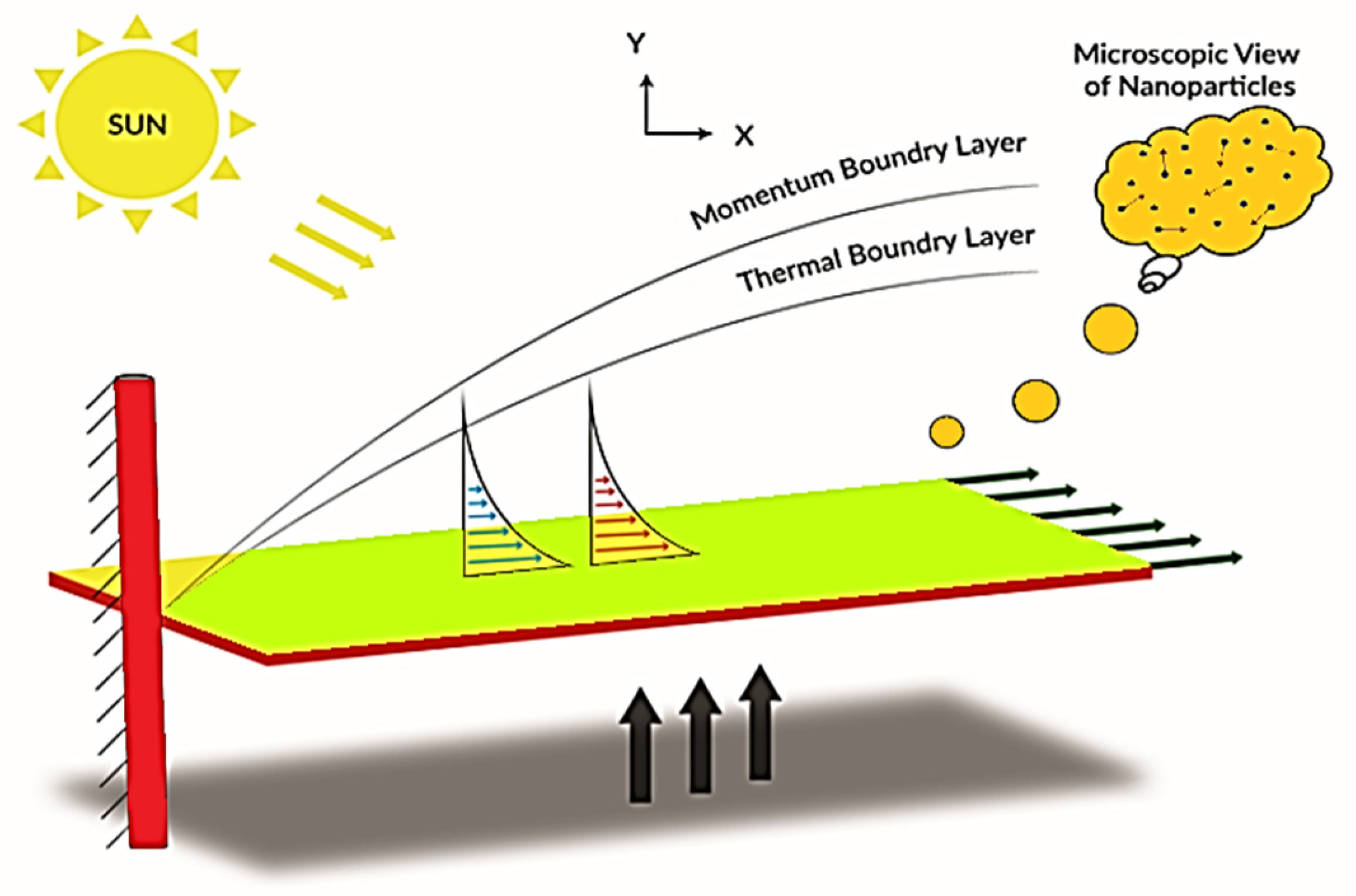
- The sun’s solar energy falls on the PTSC’s cylindrical surface, and this energy is available in the form of heat energy. Because of the nanoparticles floating in the base fluid pass across PTSC, this energy has the greatest power. The incorporation of physical phenomena like thermal radiation and thermal conductivity increases the PTSC’s heat storage capacity, which is the heart of the present theoretical experiment.
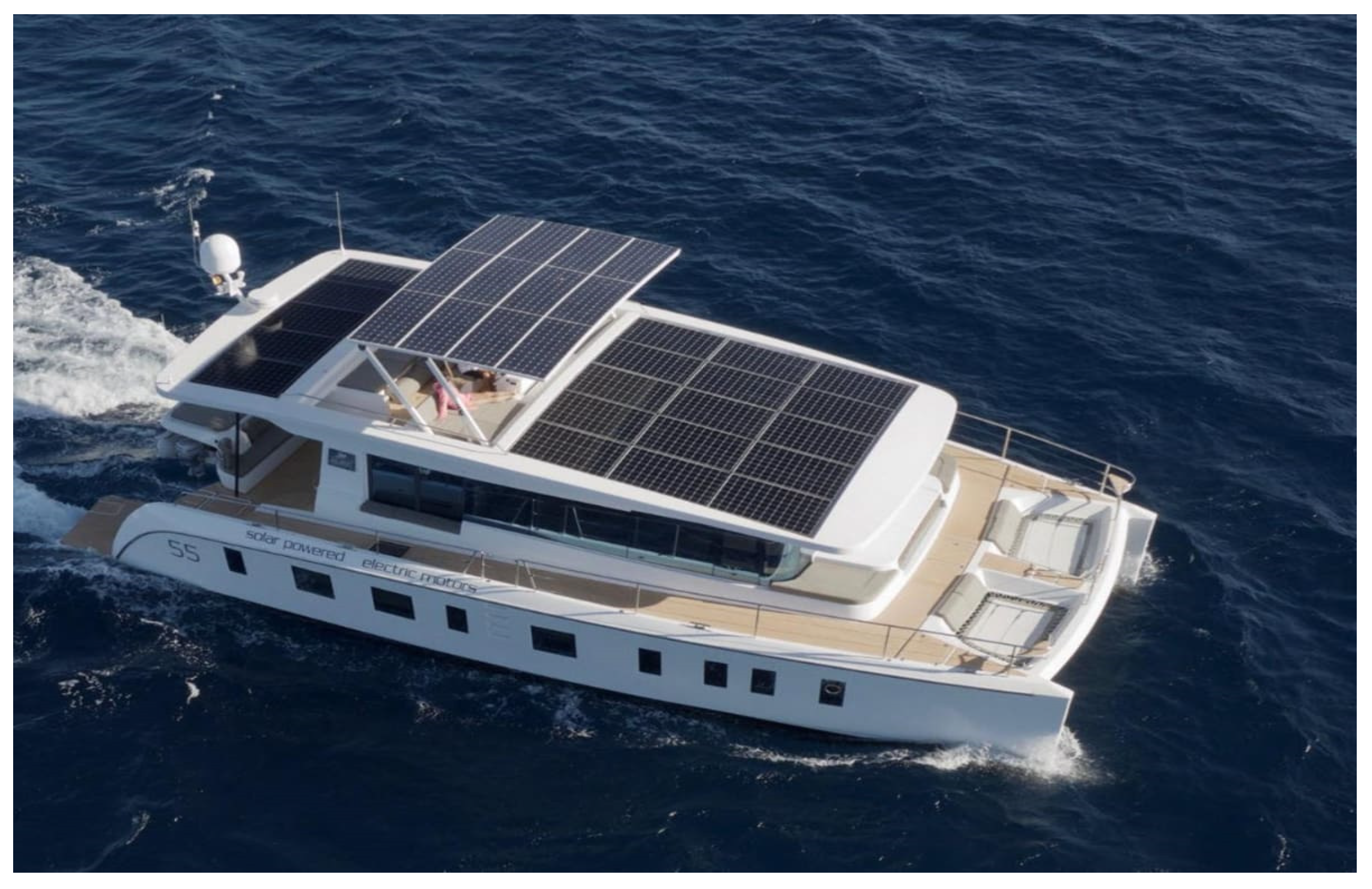
- At the surface of PTSC, the greatest solar energy is stored in the form of thermal energy. The next step is to convert this energy into electrical energy, which will be utilized for navigation and electronic lighting. The solar cells battery, which is located within the fuel area box of the powered spacecraft, converts this heat energy into electrical energy. The battery stores energy throughout the day and uses it to power during the night.
- The contribution of electrical energy to activities like as avionics, electric navigational lamps, and military communication is entirely reliant on the number of energies held or stored by the battery in terms of electrical energy.
2. Mathematical Formulation
3. The Solution for the Problem
4. Numerical Technique
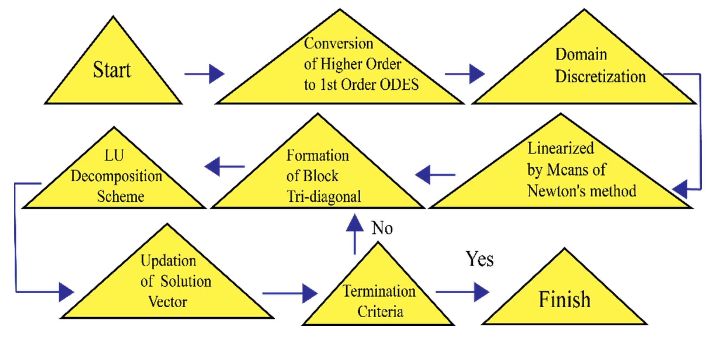
- The controlling equations must first be formulated as a set of first-order equations.
- The domain is discretized once the order of equations is reduced, allowing us to calculate the estimated solution across each subdomain rather than the full domain. This produces more accurate findings.
- Central difference derivatives and the average of function mid-points are utilized to create finite-difference equations.
- The outcoming formulas are then linearized utilizing Newton’s technique and written in tridiagonal matrix form, as Keller explained.
- Finally, the outcome is obtained by LU analysis.
5. Code Validation
6. Results and Discussion
6.1. Effect of Maxwell Parameter ()
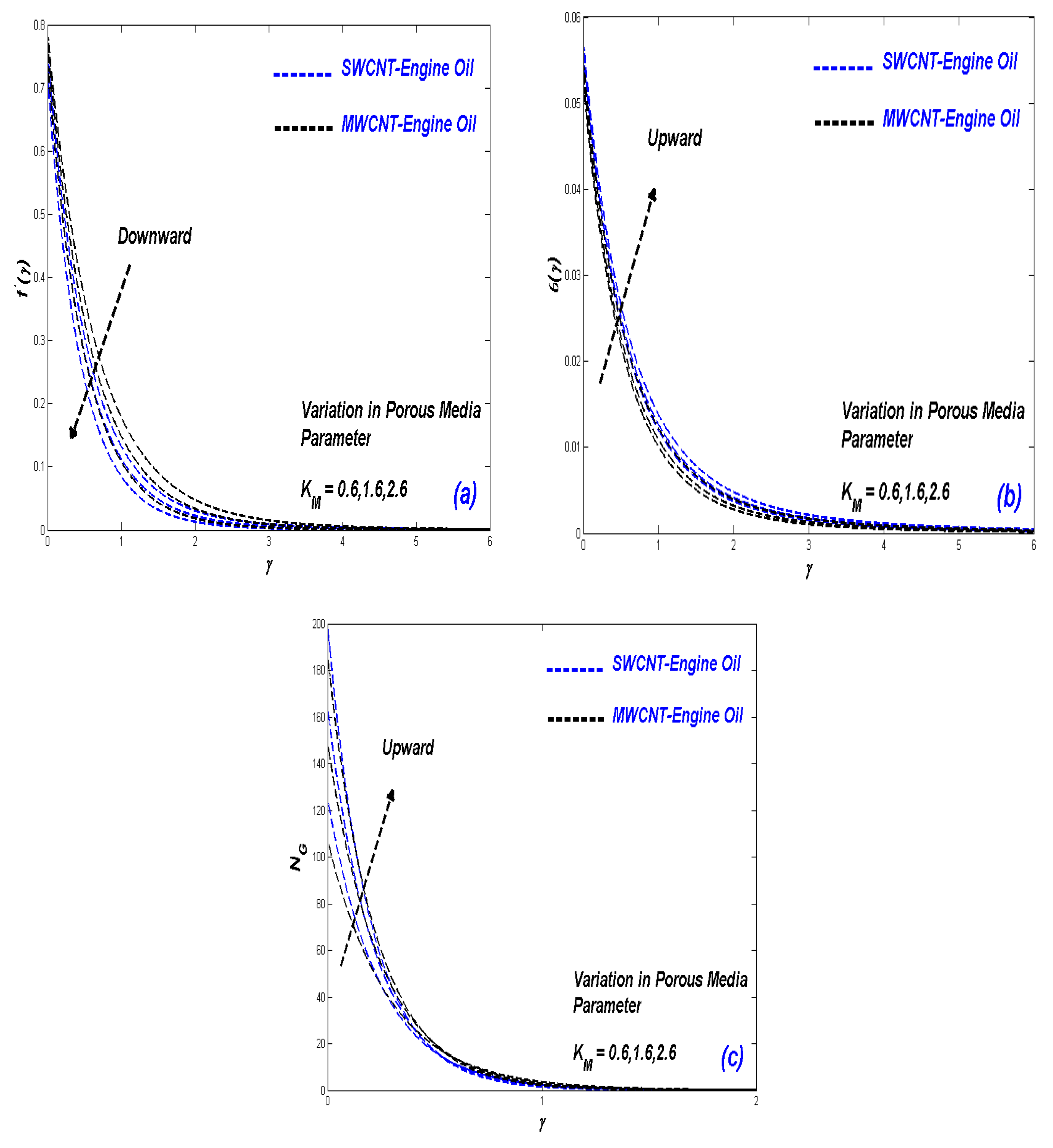
6.2. Impact of Porous Media Parameter ()
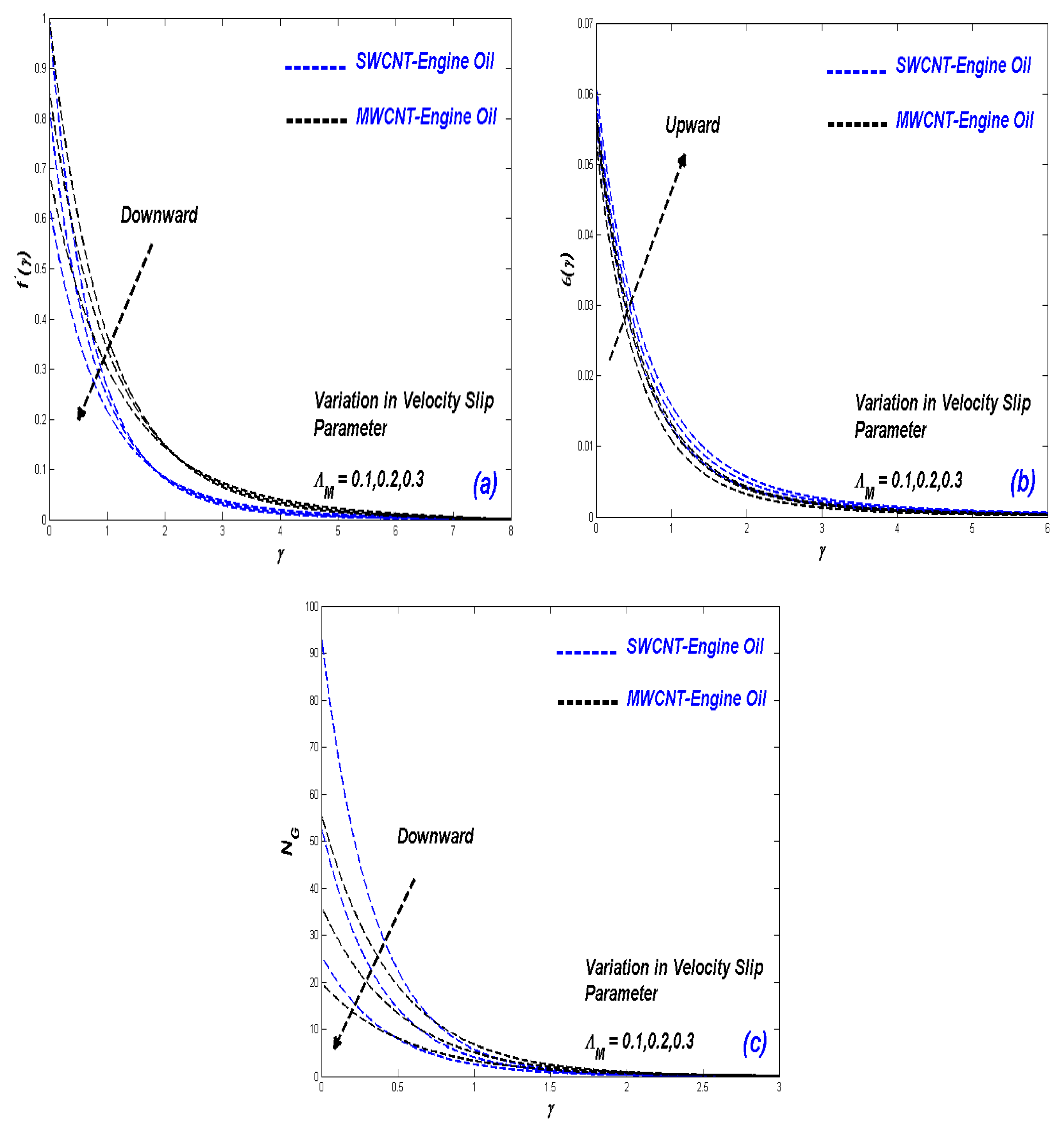
6.3. Effect of Velocity Slip Parameter
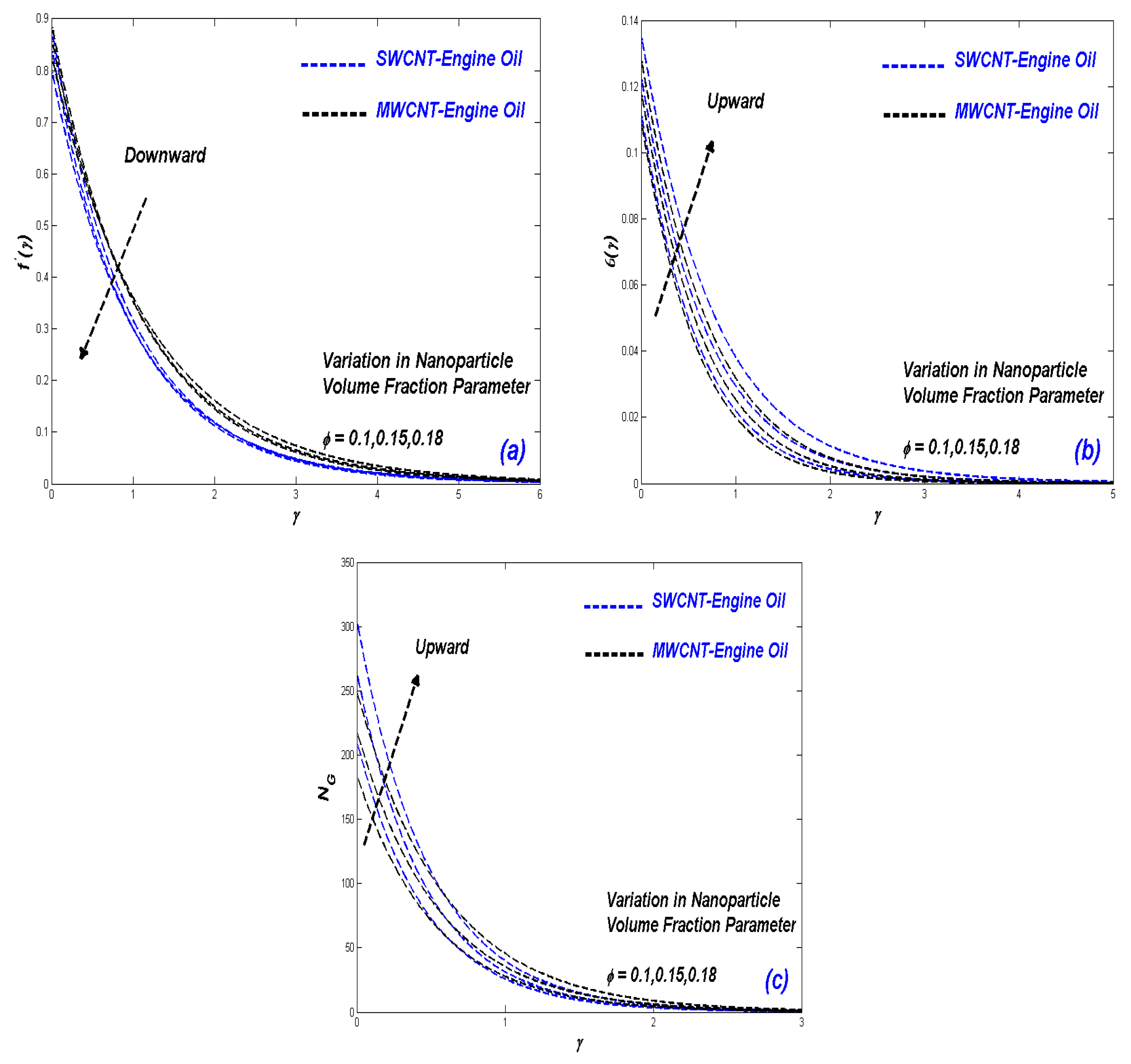
6.4. Impact of Nanoparticle Fractional Volume Parameter ()
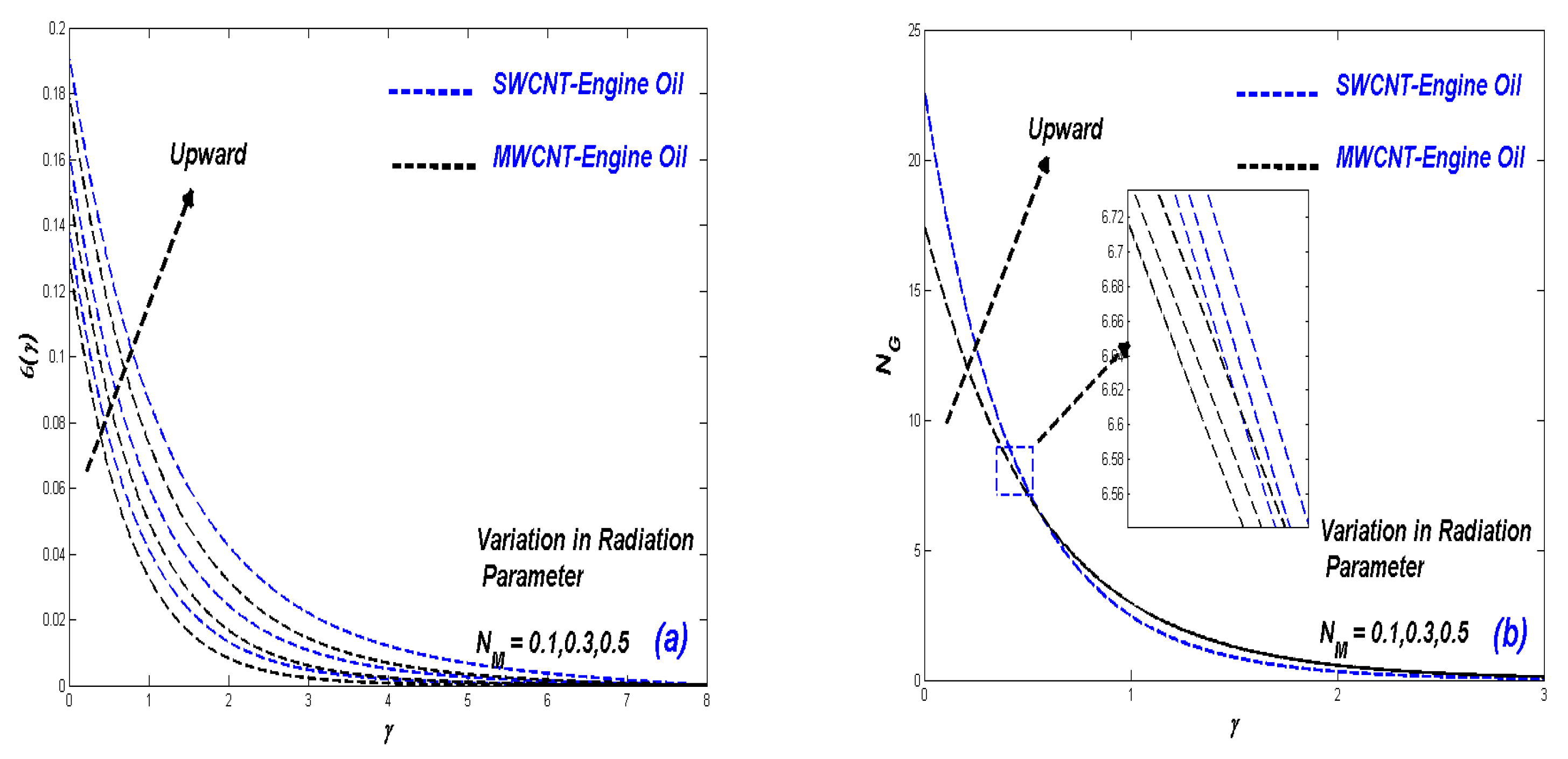
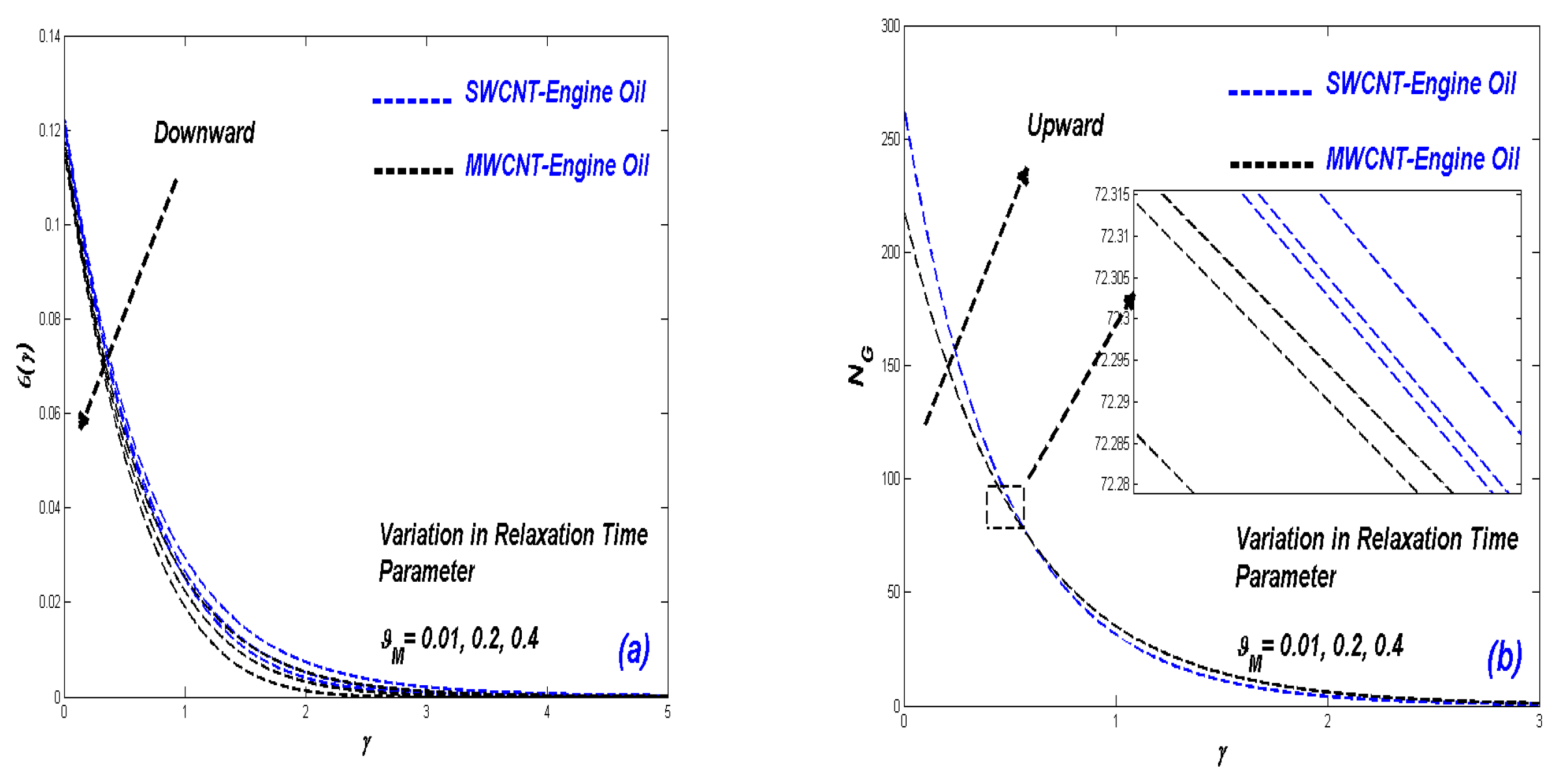
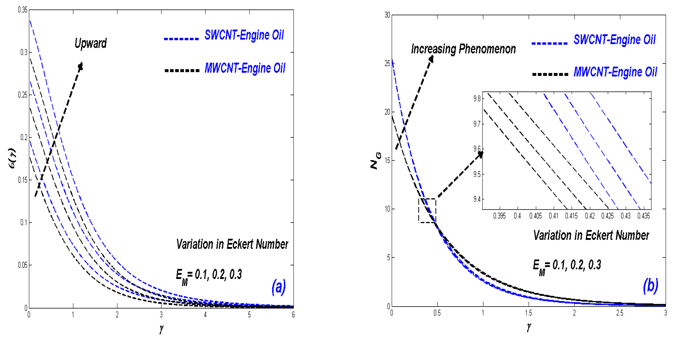
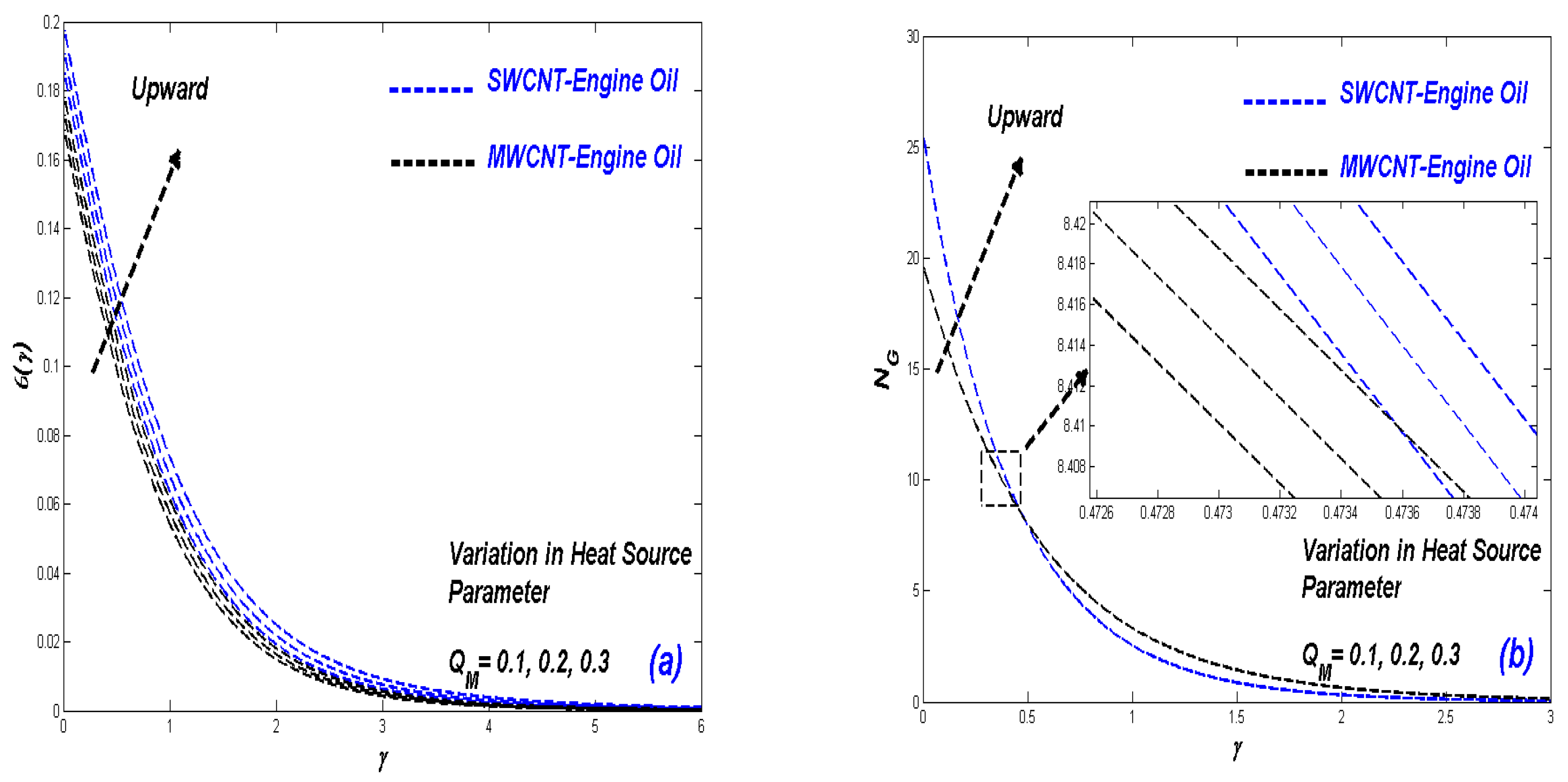
6.5. Impact of Radiative Heat Flux Parameter, Relaxation Time Parameter, Eckert Number, and Heat Source Parameter
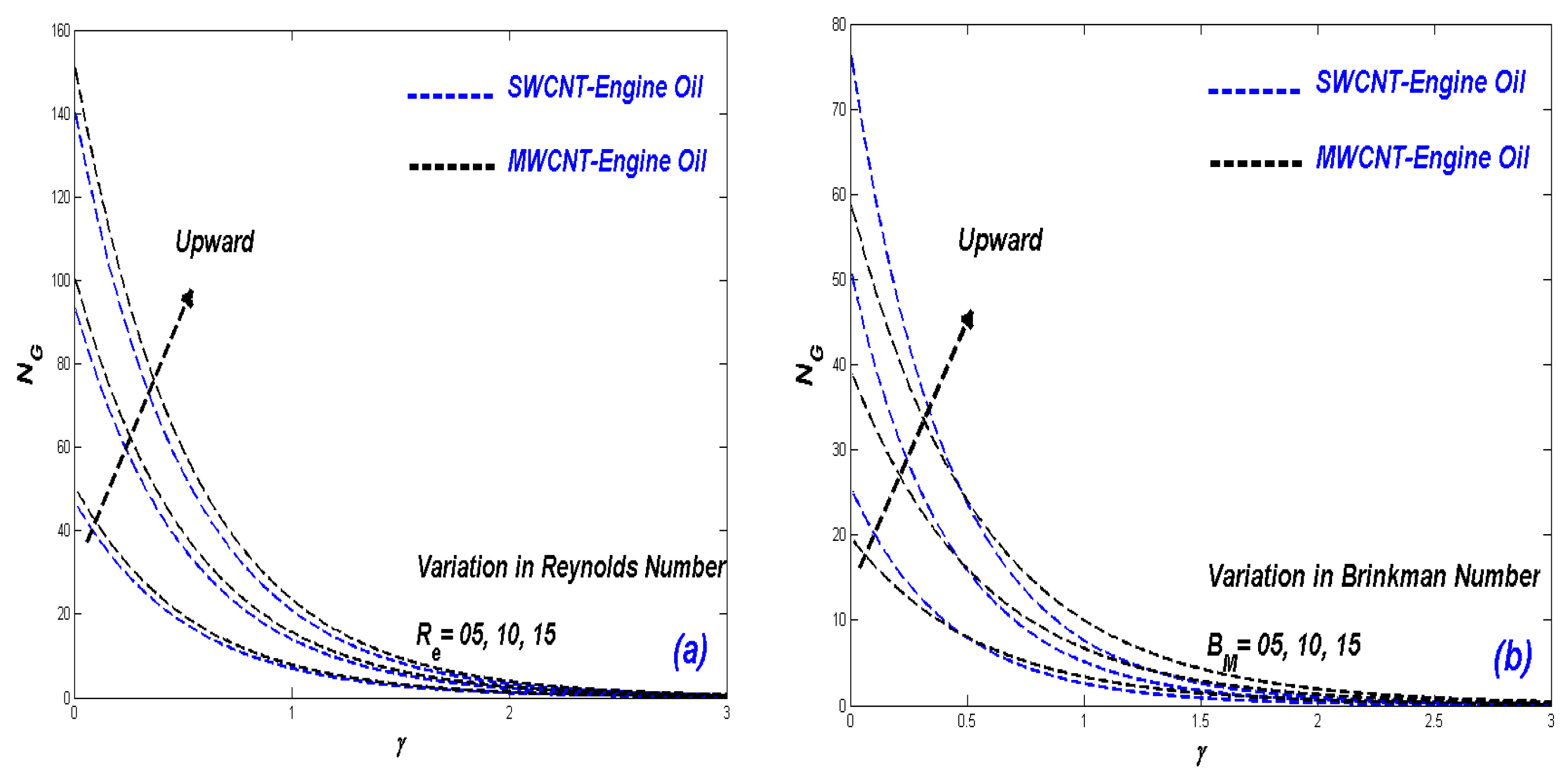
6.6. Influence of Reynolds and Brinkman Numbers on Entropy Generation
6.7. Relative Heat Transfer Rate in SWCNT-EO and MWCNT-EO Nanofluids
7. Conclusions
- ▪
- SWCNT/EO nanofluid phase is observed to achieve superior thermal radiative enhancement relative to MWCNT/EO nanofluid phase.
- ▪
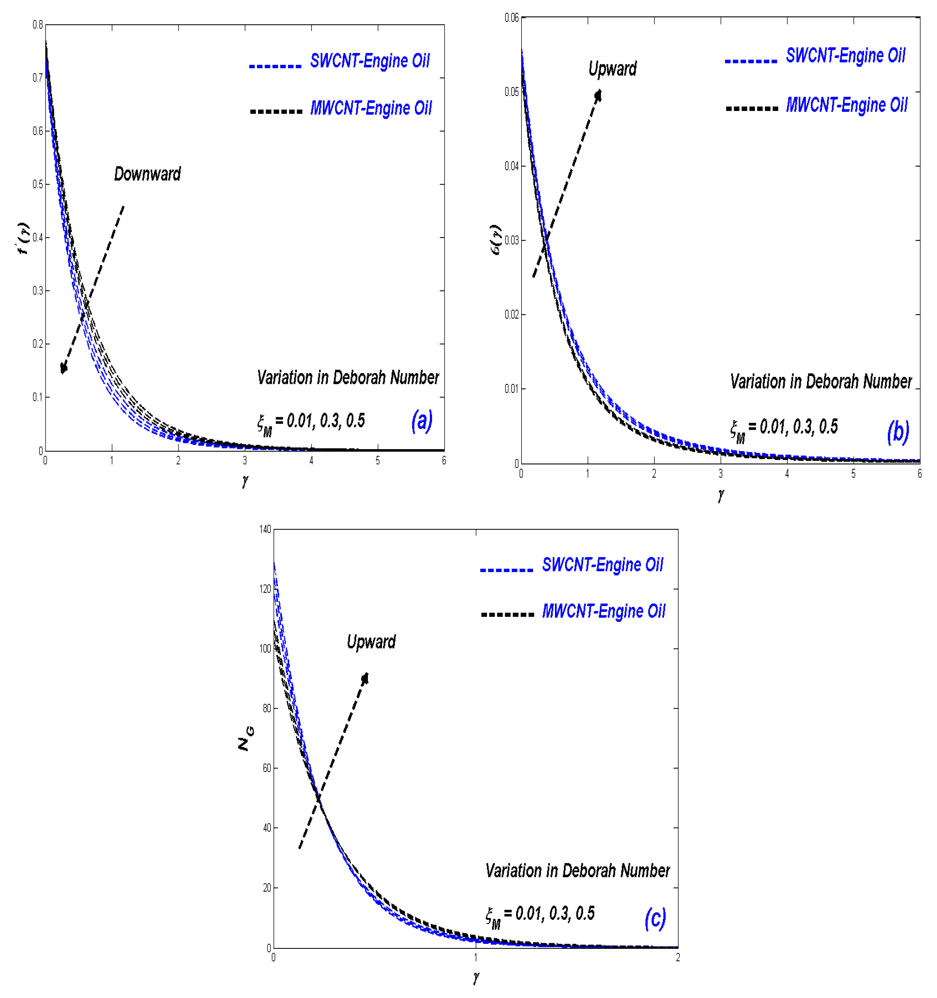
- Increasing Deborah number , porous media parameter , velocity slip parameter , nanomaterial term and relaxation time produces a significant diminution in the velocity field.
- ▪
- Velocity slip parameter has a negative effect on velocity and entropy but opposite in temperature distribution.
- ▪
- In the presence of nanomaterials, radiative, viscidness dissipative flow, and heat generation, the thickener of the thermal boundary-layer increases with time, which results in a diminished heat exchange rate.
- ▪
- Plots for entropy generation number against radiative flux, relaxation time, Eckert number, and heat generation explore dual behavior.
- ▪
- Porosity, heat generation, enthalpy, and solar radiation have an important role in the improvement of heat phenomena.
- ▪
- Relative heat transfer rate is strongly elevated with greater porous medium permeability (1.6% to 14.9%).
Author Contributions
Funding
Institutional Review Board Statement
Informed Consent Statement
Data Availability Statement
Acknowledgments
Conflicts of Interest
References
- Tuncer, A.D.; Sözen, A.; Afshari, F.; Khanlari, A.; Şirin, C.; Gungor, A. Testing of a novel convex-type solar absorber drying chamber in dehumidification process of municipal sewage sludge. J. Clean. Prod. 2020, 272, 122862. [Google Scholar] [CrossRef]
- Bayrak, F.; Oztop, H.F.; Selimefendigil, F. Experimental study for the application of different cooling techniques in photovoltaic (PV) panels. Energy Conver. Manag. 2020, 212, 112789. [Google Scholar] [CrossRef]
- Ktistis, P.K.; Agathokleous, R.A.; Kalogirou, S.A. Experimental performance of a parabolic trough collector system for an industrial process heat application. Energy 2021, 215, 119288. [Google Scholar] [CrossRef]
- Jaaz, A.H.; Hasan, H.A.; Sopian, K.; Ruslan, M.H.B.H.; Zaidi, S.H. Design and development of compound parabolic concentrating for photovoltaic solar collector: Review. Renew. Sustain. Energy Rev. 2017, 76, 1108–1121. [Google Scholar] [CrossRef]
- Bellos, E.; Tzivanidis, C. Alternative designs of parabolic trough solar collectors. Prog. Energy Combust. Sci. 2018, 71, 81–117. [Google Scholar] [CrossRef]
- Fredriksson, J.; Eickhoff, M.; Giese, L.; Herzog, M. A comparison and evaluation of innovative parabolic trough collector concepts for large-scale application. Sol. Energy 2021, 215, 266–310. [Google Scholar] [CrossRef]
- Mahian, O.; Kianifar, A.; Kalogirou, S.A.; Pop, I.; Wongwises, S. A review of the applications of nanofluids in solar energy. Int. J. Heat Mass Transf. 2013, 57, 582–594. [Google Scholar] [CrossRef]
- Khanlari, A.; Sözen, A.; Variyenli, H.İ.; Gürü, M. Comparison between heat transfer characteristics of TiO2/deionized water and kaolin/deionized water nanofluids in the plate heat exchanger. Heat Transf. Res. 2019, 50, 435–450. [Google Scholar] [CrossRef]
- Sözen, A.; Gürü, M.; Khanlari, A.; Çiftçi, E. Experimental and numerical study on enhancement of heat transfer characteristics of a heat pipe utilizing aqueous clinoptilolite nanofluid. Appl. Therm. Eng. 2019, 160, 114001. [Google Scholar] [CrossRef]
- Badali, Y.; Koçyiğit, S.; Aytimur, A.; Altındal, Ş.; Uslu, I. Synthesis of boron and rare earth stabilized graphene doped polyvinylidene fluoride (PVDF) nanocomposite piezoelectric materials. Polym. Compos. 2019, 40, 3623–3633. [Google Scholar] [CrossRef]
- Çiftçi, E. Simulation of nucleate pool boiling heat transfer characteristics of the aqueous kaolin and bauxite nanofluids. Heat Transf. Res. 2021, 52, 77–92. [Google Scholar] [CrossRef]
- Sun, Y.W.; Yan, X.P.; Yuan, C.Q.; Lei, C.W. Research progress in marine grid-connected photovoltaic technology. In Proceedings of the 47th Annual Conference of the Australian and New Zealand Solar Energy Society (ANZSES), Townsville, Australia, 29 September–2 October 2009. [Google Scholar]
- Glykas, A.; Papaioannou, G.; Perissakis, S. Application and cost–benefit analysis of solar hybrid power installation on merchant marine vessels. Ocean Eng. 2010, 37, 592–602. [Google Scholar] [CrossRef]
- Sulaiman, O. Feasibility of using solar as a supporting hybrid power system for marine diesel engine: UMT vessel experimentation experience. Glob. J. Inf. Technol. Comput. Sci. 2012, 1, 1–7. [Google Scholar]
- Lee, K.-J.; Shin, D.-S.; Lee, J.-P.; Yoo, D.-W.; Choi, H.-K.; Kim, H.-J. Hybrid photovoltaic/diesel green ship operating in standalone and grid-connected mode in South Korea-Experimental investigation. In Proceedings of the 2012 IEEE Vehicle Power and Propulsion Conference, Seoul, Korea, 9–12 October 2012; pp. 580–583. [Google Scholar]
- Babu, S.; Jain, J.V. On-board solar power for small-scale distant-water fishing vessels. In Proceedings of the 2013 IEEE Global Humanitarian Technology Conference (GHTC), San Jose, CA, USA, 20–23 October 2013. [Google Scholar]
- Cristea, O. Testing of PV module efficiency in naval conditions. In Proceedings of the 2013 8th International Symposium on Advanced Topics In Electrical Engineering (Atee), Bucharest, Romania, 23–25 May 2013. [Google Scholar]
- Kirkpatrick, J.P. An Investigation of the Effectiveness of Solar Power on Navy Surface Combatants. Naval Post-Graduate School Monterey Ca. 2013. Available online: http://hdl.handle.net/10945/37652 (accessed on 1 November 2021).
- Kobougias, I.C.; Tatakis, E.C.; Prousalidis, J. PV Systems Installed in Marine Vessels: Technologies and Specifications. Adv. Power Electron. 2013, 2013, 831560. [Google Scholar] [CrossRef] [Green Version]
- Utama, I.K.A.P.; Santosa, P.I.; Chao, R.M.; Nasiruddin, A. New concept of solar-powered catamaran fishing vessel. In Proceeding of the 7th International Conference on Asian and Pasific Coasts, Hong Kong, 14–16 December 2011. [Google Scholar]
- Yufang, Z.; Peng, Q.; Hong, Y. Fuel free ship, design for next generation. In Proceedings of the 2013 Eighth International Conference and Exhibition on Ecological Vehicles and Renewable Energies (EVER), Manhattan, NY, USA, 27–30 March 2013; pp. 1–5. [Google Scholar]
- Alfonsín, V.; Suarez, A.; Cancela, A.; Sanchez, A.; Maceiras, R. Modelization of hybrid systems with hydrogen and renewable energy oriented to electric propulsion in sailboats. Int. J. Hydrogen Energy 2014, 39, 11763–11773. [Google Scholar] [CrossRef]
- Cristea, O.; Popescu, M.-O.; Calinciuc, A.S. A correlation between simulated and real PV system in naval conditions. In Proceedings of the 2014 International Symposium on Fundamentals of Electrical Engineering (ISFEE), Manhattan, NY, USA, 28–29 November 2014; pp. 1–6. [Google Scholar]
- Hussein, A.W.; Ahmed, M.W. Solar Energy: Solution to fuel dilemma. Int. J. Res. Eng. Technol. 2014, 2, 99–108. [Google Scholar]
- Peng, C.; Shounan, S.; Hai, L.; Qiang, Z. Modeling and simulation of ship power system integration of solar energy. In Proceedings of the 2014 IEEE Conference and Expo Transportation Electrification Asia-Pacific (ITEC Asia-Pacific), Beijing, China, 31 August–3 September 2014; pp. 1–5. [Google Scholar]
- Lan, H.; Wen, S.; Hong, Y.-Y.; Yu, D.C.; Zhang, L. Optimal sizing of hybrid PV/diesel/battery in ship power system. Appl. Energy 2015, 158, 26–34. [Google Scholar] [CrossRef] [Green Version]
- Lan, H.; Dai, J.; Wen, S.; Hong, Y.Y.; Yu, D.C.; Bai, Y. Optimal tilt angle of photovoltaic arrays and economic alloca-tion of energy storage system on large oil tanker ship. Energies 2015, 8, 11515–11530. [Google Scholar] [CrossRef]
- Tang, X.-J.; Wang, T.; Zhi, C.; Huang, Y.-M.; Xu-Jing, T. The design of power management system for solar ship. In Proceedings of the 2015 International Conference on Transportation Information and Safety (ICTIS), Wuhan, China, 25–28 June 2015; pp. 548–553. [Google Scholar]
- Zhang, Y.; Sun, Y.; Luo, H.; Wang, Y. Study on effect of ship low frequency vibration on the output characteristics of PV cells under different solar irradiation. In Proceedings of the 2015 International Conference on Renewable Energy Research and Applications (ICRERA), Palermo, Italy, 22–25 November 2015; pp. 388–392. [Google Scholar]
- Wen, S.; Lan, H.; Hong, Y.-Y.; Yu, D.C.; Zhang, L.; Cheng, P. Allocation of ESS by interval optimization method considering impact of ship swinging on hybrid PV/diesel ship power system. Appl. Energy 2016, 175, 158–167. [Google Scholar] [CrossRef]
- Salleh, N.A.S.; Muda, W.M.W.; Abdullah, S.S. Feasibility study of optimization and economic analysis for grid-connected renewable energy electric boat charging station in Kuala Terengganu. In Proceedings of the 2015 IEEE Conference on Energy Conversion (CENCON), Johor Bahru, Malaysia, 19–20 October 2015; pp. 510–515. [Google Scholar]
- Jia, J.; Dong, H. Research on ship power plant simulation system based on LabVIEW and MATLAB mixed program-ming. In Proceedings of the 2017 IEEE 2nd Information Technology, Networking, Electronic and Automation Control Conference (ITNEC), Chengdu, China, 15–17 December 2017. [Google Scholar]
- Tang, R.L.; Wu, Z.; Fang, Y.J. Withdrawn: Design of Green Ships with Large-Scale Photovoltaic Arrays and Intelli-Gent MPPT Control. Appl. Energy 2017. [Google Scholar] [CrossRef]
- Yuan, Y.; Wang, J.; Yan, X.; Li, Q.; Long, T. A design and experimental investigation of a largescale solar ener-gy/diesel generator powered hybrid ship. Energy 2018, 165, 965–978. [Google Scholar] [CrossRef]
- The Rise of Solar-Powered Yachts With Unlimited Range. Available online: https://citimarineyachts.com/technology/the-rise-of-solar-powered-yachts-with-unlimited-range/ (accessed on 30 September 2021).
- Al-Rashed, A.A.; Oztop, H.F.; Kolsi, L.; Boudjemline, A.; Almeshaal, M.A.; Ali, M.E.; Chamkha, A. CFD study of heat and mass transfer and entropy generation in a 3D solar distiller heated by an internal column. Int. J. Mech. Sci. 2019, 152, 280–288. [Google Scholar] [CrossRef]
- Sözen, A.; Şirin, C.; Khanlari, A.; Tuncer, A.D.; Gürbüz, E.Y. Thermal performance enhancement of tube-type alterna-tive indirect solar dryer with iron mesh modification. Solar Energy 2020, 207, 1269–1281. [Google Scholar] [CrossRef]
- Selimefendigil, F.; Öztop, H.F. Performance assessment of a thermoelectric module by using rotating circular cylinders and nanofluids in the channel flow for renewable energy applications. J. Clean. Prod. 2021, 279, 123426. [Google Scholar] [CrossRef]
- Ghasemi, S.E.; Ahangar, G.H.R.M. Numerical analysis of performance of solar parabolic trough collector with Cu-Water nanofluid. Int. J. Nano Dimens. 2014, 5, 233–240. [Google Scholar]
- Subramani, J.; Sevvel, P.; Anbuselvam; Srinivasan, S. Influence of CNT coating on the efficiency of solar parabolic trough collector using AL2O3 nanofluids—A multiple regression approach. Mater. Today Proc. 2021, 45, 1857–1861. [Google Scholar] [CrossRef]
- Hachicha, A.A.; Said, Z.; Rahman, S.; Al-Sarairah, E. On the thermal and thermodynamic analysis of parabolic trough collector technology using industrial-grade MWCNT based nanofluid. Renew. Energy 2020, 161, 1303–1317. [Google Scholar] [CrossRef]
- Bellos, E.; Tzivanidis, C.; Said, Z. A systematic parametric thermal analysis of nanofluid-based parabolic trough solar collectors. Sustain. Energy Technol. Assess. 2020, 39, 100714. [Google Scholar] [CrossRef]
- Abed, N.; Afgan, I.; Cioncolini, A.; Iacovides, H.; Nasser, A.; Mekhail, T. Thermal performance evaluation of various nanofluids with non-uniform heating for parabolic trough collectors. Case Stud. Therm. Eng. 2020, 22, 100769. [Google Scholar] [CrossRef]
- Subhedar, D.G.; Chauhan, K.V.; Patel, K.; Ramani, B.M. Performance improvement of a conventional single slope single basin passive solar still by integrating with nanofluid-based parabolic trough collector: An experimental study. Mater. Today Proc. 2020, 26, 1478–1481. [Google Scholar] [CrossRef]
- Bezaatpour, M.; Rostamzadeh, H.; Bezaatpour, J. Hybridization of rotary absorber tube and magnetic field inducer with nanofluid for performance enhancement of parabolic trough solar collector. J. Clean. Prod. 2021, 283, 124565. [Google Scholar] [CrossRef]
- Rejeb, O.; Ghenai, C.; Bettayeb, M. Modeling and simulation analysis of solar absorption chiller driven by nanofluid-based parabolic trough collectors (PTC) under hot climatic conditions. Case Stud. Therm. Eng. 2020, 19, 100624. [Google Scholar] [CrossRef]
- Peng, H.; Guo, W.; Li, M. Thermal-hydraulic and thermodynamic performances of liquid metal based nanofluid in parabolic trough solar receiver tube. Energy 2020, 192, 116564. [Google Scholar] [CrossRef]
- Minea, A.A.; El-Maghlany, W.M. Influence of hybrid nanofluids on the performance of parabolic trough collectors in solar thermal systems: Recent findings and numerical comparison. Renew. Energy 2018, 120, 350–364. [Google Scholar] [CrossRef]
- O’Keeffe, G.; Mitchell, S.; Myers, T.; Cregan, V. Time-dependent modelling of nanofluid-based direct absorption parabolic trough solar collectors. Sol. Energy 2018, 174, 73–82. [Google Scholar] [CrossRef]
- Ellahi, R.; Alamri, S.Z.; Basit, A.; Majeed, A. Effects of MHD and slip on heat transfer boundary layer flow over a moving plate based on specific entropy generation. J. Taibah Univ. Sci. 2018, 12, 476–482. [Google Scholar] [CrossRef] [Green Version]
- Alamri, S.Z.; Khan, A.A.; Azeez, M.; Ellahi, R. Effects of mass transfer on MHD second grade fluid towards stretching cylinder: A novel perspective of Cattaneo–Christov heat flux model. Phys. Lett. A 2019, 383, 276–281. [Google Scholar] [CrossRef]
- Safaei, M.R.; Goshayeshi, H.R.; Chaer, I. Solar Still Efficiency Enhancement by Using Graphene Oxide/Paraffin Nano-PCM. Energies 2019, 12, 2002. [Google Scholar] [CrossRef] [Green Version]
- Sarafraz, M.; Safaei, M.R. Diurnal thermal evaluation of an evacuated tube solar collector (ETSC) charged with graphene nanoplatelets-methanol nano-suspension. Renew. Energy 2019, 142, 364–372. [Google Scholar] [CrossRef]
- Ellahi, R.; Zeeshan, A.; Abbas, T.; Hussain, F. Thermally Charged MHD Bi-Phase Flow Coatings with Non-Newtonian Nanofluid and Hafnium Particles along Slippery Walls. Coatings 2019, 9, 300. [Google Scholar] [CrossRef] [Green Version]
- Sarafraz, M.M.; Tlili, I.; Tian, Z.; Bakouri, M.; Safaei, M.R. Smart optimization of a thermosyphon heat pipe for an evacuated tube solar collector using response surface methodology (RSM). Phys. A 2019, 534, 122146. [Google Scholar] [CrossRef]
- Eid, M.R.; Mahny, K.; Al-Hossainy, A.F. Homogeneous-heterogeneous catalysis on electromagnetic radiative Prandtl fluid flow: Darcy-Forchheimer substance scheme. Surf. Interfaces 2021, 24, 101119. [Google Scholar] [CrossRef]
- Maithani, R.; Kumar, A.; Zadeh, P.G.; Safaei, M.R.; Gholamalizadeh, E. Empirical correlations development for heat transfer and friction factor of a solar rectangular air passage with spherical-shaped turbulence promoters. J. Therm. Anal. Calorim. 2020, 139, 1195–1212. [Google Scholar] [CrossRef]
- Elelamy, A.F.; Elgazery, N.S.; Ellahi, R. Blood flow of MHD non-Newtonian nanofluid with heat transfer and slip effects: Application of bacterial growth in heart valve. Int. J. Numer. Meth. 2020, 30, 4883–4908. [Google Scholar] [CrossRef]
- Goshayeshi, H.R.; Safaei, M.R. Effect of absorber plate surface shape and glass cover inclination angle on the performance of a passive solar still. Int. J. Numer. Meth. 2020, 30, 3183–3198. [Google Scholar] [CrossRef]
- Jathar, L.D.; Ganesan, S.; Shahapurkar, K.; Soudagar, M.E.M.; Mujtaba, M.A.; Anqi, A.E.; Farooq, M.; Khidmatgar, A.; Goodarzi, M.; Safaei, M.R. Effect of various factors and diverse approaches to enhance the performance of solar stills: A comprehensive review. J. Therm. Anal. Calorim. 2021, 1–32. [Google Scholar] [CrossRef]
- Khosravi, R.; Rabiei, S.; Khaki, M.; Safaei, M.R.; Goodarzi, M. Entropy generation of graphene–platinum hybrid nanofluid flow through a wavy cylindrical microchannel solar receiver by using neural networks. J. Therm. Anal. Calorim. 2021, 145, 1949–1967. [Google Scholar] [CrossRef]
- Jamshed, W.; Devi, S.U.S.; Goodarzi, M.; Prakash, M.; Nisar, K.S.; Zakarya, M.; Abdel-Aty, A.H. Evaluating the unsteady Casson nanofluid over a stretching sheet with solar thermal radiation: An optimal case study. Case Stud. Therm. Eng. 2021, 26, 101148. [Google Scholar] [CrossRef]
- Wang, Q.; Pei, G.; Yang, H. Techno-economic assessment of performance-enhanced parabolic trough receiver in concentrated solar power plants. Renew. Energy 2021, 167, 629–643. [Google Scholar] [CrossRef]
- Wang, Q.; Shen, B.; Huang, J.; Yang, H.; Pei, G.; Yang, H. A spectral self-regulating parabolic trough solar receiver integrated with vanadium dioxide-based thermochromic coating. Appl. Energy 2021, 285, 116453. [Google Scholar] [CrossRef]
- Tyagi, S.K.; Wang, S.W.; Singhal, M.K.; Kaushik, S.C.; Park, S.R. Exergy analysis and parametric study of concentrating type solar collectors. Int. J. Therm. Sci. 2007, 46, 1304–1310. [Google Scholar] [CrossRef]
- Smit, S.; Kessels, W. Variational method for the minimization of entropy generation in solar cells. J. Appl. Phys. 2015, 117, 134504. [Google Scholar] [CrossRef] [Green Version]
- Gupta, M.; Kaushik, S. Exergetic performance evaluation and parametric studies of solar air heater. Energy 2008, 33, 1691–1702. [Google Scholar] [CrossRef]
- Ebrahimi-Moghadam, A.; Mohseni-Gharyehsafa, B.; Farzaneh-Gord, M. Using artificial neural network and quadratic algorithm for minimizing entropy generation of Al2O3-EG/W nanofluid flow inside parabolic trough solar collector. Renew. Energy 2018, 129, 473–485. [Google Scholar] [CrossRef]
- Mwesigye, A.; Huan, Z.; Meyer, J.P. Thermal performance and entropy generation analysis of a high concentration ratio parabolic trough solar collector with Cu-Therminol®VP-1 nanofluid. Energy Convers. Manag. 2016, 120, 449–465. [Google Scholar] [CrossRef] [Green Version]
- Akbarzadeh, S.; Valipour, M.S. Energy and exergy analysis of a parabolic trough collector using helically corrugated ab-sorber tube. Renew. Energy 2020, 155, 735–747. [Google Scholar] [CrossRef]
- Jamshed, W.; Aziz, A. A comparative entropy based analysis of Cu and Fe3O4/methanol Powell-Eyring nanofluid in solar thermal collectors subjected to thermal radiation, variable thermal conductivity and impact of different nanoparticles shape. Results Phys. 2018, 9, 195–205. [Google Scholar] [CrossRef]
- Aziz, A.; Jamshed, W.; Aziz, T. Mathematical model for thermal and entropy analysis of thermal solar collectors by using Maxwell nanofluids with slip conditions, thermal radiation and variable thermal conductivity. Open Phys. 2018, 16, 123–136. [Google Scholar] [CrossRef]
- Mukhtar, T.; Jamshed, W.; Aziz, A.; Al-Kouz, W. Computational investigation of heat transfer in a flow subjected to magnetohydrodynamic of Maxwell nanofluid over a stretched flat sheet with thermal radiation. Numer. Methods Partial. Differ. Equ. 2020, 1–21. [Google Scholar] [CrossRef]
- Jamshed, W.; Shahzad, F.; Safdar, R.; Sajid, T.; Eid, M.R.; Nisar, K.S. Implementing renewable solar energy in presence of Maxwell nanofluid in parabolic trough solar collector: A computational study. Waves Random Complex Media 2021, 1–32. [Google Scholar] [CrossRef]
- Jamshed, W.; Devi, S.U.S.; Safdar, R.; Redouane, F.; Nisar, K.S.; Eid, M.R. Comprehensive analysis on copper-iron (II, III)/oxide-engine oil Casson nanofluid flowing and thermal features in parabolic trough solar collector. J. Taibah Univer. Sci. 2021, 15, 619–636. [Google Scholar] [CrossRef]
- Jamshed, W. Thermal augmentation in solar aircraft using tangent hyperbolic hybrid nanofluid: A solar energy application. Energy Environ. 2021, 1–44. [Google Scholar] [CrossRef]
- Jamshed, W.; Nisar, K.S.; Ibrahim, R.W.; Shahzad, F.; Eid, M.R. Thermal expansion optimization in solar aircraft using tangent hyperbolic hybrid nanofluid: A solar thermal application. J. Mater. Res. Technol. 2021, 14, 985–1006. [Google Scholar] [CrossRef]
- Jamshed, W.; Eid, M.R.; Mohd Nasir, N.A.A.; Nisar, K.S.; Aziz, A.; Shahzad, F.; Saleel, C.A.; Shukla, A. Thermal examination of renewable solar energy in parabolic trough solar collector utilizing Maxwell nanofluid: A noble case study. Case Stud. Therm. Eng. 2021, 27, 101258. [Google Scholar] [CrossRef]
- Jamshed, W. Numerical investigation of MHD impact on Maxwell nanofluid. Int. Commun. Heat Mass Transf. 2021, 120, 104973. [Google Scholar] [CrossRef]
- Brewster, M.Q. Thermal Radiative Transfer and Properties; John Wiley and Sons: Hoboken, NJ, USA, 1992. [Google Scholar]
- Muhammad, K.; Hayat, T.; Alsaedi, A.; Ahmed, B. A comparative study for convective fow of basefuid (gasoline oil), nanomaterial (SWCNTs) and hybrid nanomaterial (SWCNTs + MWCNTs). Appl. Nanosci. 2020, 11, 9–20. [Google Scholar] [CrossRef]
- Jamshed, W.; Nisar, K.S.; Ibrahim, R.W.; Mukhtar, T.; Vijayakumar, V.; Ahmed, F. Computational frame work of Cattaneo-Christov heat flux effects on Engine Oil based Williamson hybrid nanofluids: A thermal case study. Case Stud. Therm. Eng. 2021, 26, 101179. [Google Scholar] [CrossRef]
- Aziz, A.; Jamshed, W.; Aziz, T.; Bahaidarah, H.M.S.; Rehman, K.U. Entropy analysis of Powell–Eyring hybrid nanofluid including effect of linear thermal radiation and viscous dissipation. J. Therm. Anal. Calorim. 2021, 143, 1331–1343. [Google Scholar] [CrossRef]
- Das, S.; Chakraborty, S.; Jana, R.N. and Makinde, O.D. Entropy analysis of unsteady magnetonanofluid flow past accelerating stretching sheet with convective boundary condition. Appl. Math. Mech. 2015, 36, 1593–1610. [Google Scholar] [CrossRef]
- Keller, H.B. A New Difference Scheme for Parabolic Problems; Hubbard, B., Ed.; Numerical Solutions of Partial Differential Equations; Academic Press: New York, NY, USA, 1971; pp. 327–350. [Google Scholar]
- Wang, C.Y. Free convection on a vertical stretching surface. Appl. Math. Mech. 1989, 69, 418–420. [Google Scholar] [CrossRef]
- Gorla, R.S.R.; Sidawi, I. Free convection on a vertical stretching surface with suction and blowing. Flow Turbul. Combust. 1994, 52, 247–257. [Google Scholar] [CrossRef]


| Properties | Expression |
|---|---|
| Density | |
| Dynamic viscidness | |
| Heat capacity | |
| Thermal conductivity |
| Material | |||
|---|---|---|---|
| Engine oil (EO) | 884 | 1910 | 0.14 |
| SWCNT | 2600 | 425 | 6000 |
| MWCNT | 1600 | 796 | 3000 |
| Wang [86] | Gorla & Sidawi [87] | This Study | |
|---|---|---|---|
| 0.20 | 0.1691 | 0.1691 | 0.1691 |
| 0.70 | 0.4539 | 0.4539 | 0.4537 |
| 2.00 | 0.9114 | 0.9114 | 0.9114 |
| 7.00 | 1.8954 | 1.8954 | 1.8958 |
| Relative | |||||||||||||
|---|---|---|---|---|---|---|---|---|---|---|---|---|---|
| SWCNT-EO | MWCNT-EO | SWCNT-EO | MWCNT-EO | ||||||||||
| 0.01 | 0.6 | 0.3 | 0.2 | 0.18 | 0.1 | 0.1 | 0.3 | 0.1 | 2.5826 | 2.3208 | 0.1726 | 0.1638 | 5.0% |
| 0.3 | 2.6762 | 2.4239 | 0.1569 | 0.1409 | 10.1% | ||||||||
| 0.5 | 2.7442 | 2.4631 | 0.1488 | 0.1279 | 14.0% | ||||||||
| 0.6 | 2.5826 | 2.3208 | 0.1726 | 0.1638 | 5.0% | ||||||||
| 1.6 | 2.7734 | 2.5285 | 0.1623 | 0.1401 | 13.6% | ||||||||
| 2.6 | 2.9345 | 2.7110 | 0.1484 | 0.1262 | 14.9% | ||||||||
| 0.1 | 2.5826 | 2.3208 | 0.1935 | 0.1899 | 1.8% | ||||||||
| 0.2 | 2.5826 | 2.3208 | 0.1851 | 0.1788 | 3.4% | ||||||||
| 0.3 | 2.5826 | 2.3208 | 0.1726 | 0.1638 | 5.0% | ||||||||
| 0.01 | 2.5826 | 2.3208 | 0.1632 | 0.1563 | 4.2% | ||||||||
| 0.2 | 2.5826 | 2.3208 | 0.1726 | 0.1638 | 5.0% | ||||||||
| 0.4 | 2.5826 | 2.3208 | 0.1843 | 0.1739 | 5.6% | ||||||||
| 0.1 | 2.1446 | 1.9783 | 0.1927 | 0.1895 | 1.6% | ||||||||
| 0.15 | 2.2437 | 2.2127 | 0.1896 | 0.1806 | 4.7% | ||||||||
| 0.18 | 2.5826 | 2.3208 | 0.1726 | 0.1638 | 5.0% | ||||||||
| 0.1 | 2.5826 | 2.3208 | 0.1726 | 0.1638 | 5.0% | ||||||||
| 0.2 | 2.3663 | 2.2235 | 0.1510 | 0.1409 | 6.6% | ||||||||
| 0.3 | 1.9829 | 1.8412 | 0.1382 | 0.1223 | 11.5% | ||||||||
| 0.1 | 2.5826 | 2.3208 | 0.1726 | 0.1638 | 5.0% | ||||||||
| 0.2 | 2.5826 | 2.3208 | 0.1623 | 0.1522 | 6.2% | ||||||||
| 0.3 | 2.5826 | 2.3208 | 0.1491 | 0.1331 | 10.7% | ||||||||
| 0.1 | 2.5859 | 2.3025 | 0.1923 | 0.1830 | 4.8% | ||||||||
| 0.3 | 2.5859 | 2.3025 | 0.1726 | 0.1638 | 5.0% | ||||||||
| 0.5 | 2.5859 | 2.3025 | 0.1652 | 0.1511 | 8.5% | ||||||||
| 0.1 | 2.5859 | 2.3025 | 0.1726 | 0.1638 | 5.0% | ||||||||
| 0.2 | 2.5859 | 2.3025 | 0.1581 | 0.1439 | 8.9% | ||||||||
| 0.3 | 2.5859 | 2.3025 | 0.1343 | 0.1208 | 10.0% | ||||||||
Publisher’s Note: MDPI stays neutral with regard to jurisdictional claims in published maps and institutional affiliations. |
© 2021 by the authors. Licensee MDPI, Basel, Switzerland. This article is an open access article distributed under the terms and conditions of the Creative Commons Attribution (CC BY) license (https://creativecommons.org/licenses/by/4.0/).
Share and Cite
Jamshed, W.; Şirin, C.; Selimefendigil, F.; Shamshuddin, M.; Altowairqi, Y.; Eid, M.R. Thermal Characterization of Coolant Maxwell Type Nanofluid Flowing in Parabolic Trough Solar Collector (PTSC) Used Inside Solar Powered Ship Application. Coatings 2021, 11, 1552. https://doi.org/10.3390/coatings11121552
Jamshed W, Şirin C, Selimefendigil F, Shamshuddin M, Altowairqi Y, Eid MR. Thermal Characterization of Coolant Maxwell Type Nanofluid Flowing in Parabolic Trough Solar Collector (PTSC) Used Inside Solar Powered Ship Application. Coatings. 2021; 11(12):1552. https://doi.org/10.3390/coatings11121552
Chicago/Turabian StyleJamshed, Wasim, Ceylin Şirin, Fatih Selimefendigil, MD. Shamshuddin, Yasir Altowairqi, and Mohamed R. Eid. 2021. "Thermal Characterization of Coolant Maxwell Type Nanofluid Flowing in Parabolic Trough Solar Collector (PTSC) Used Inside Solar Powered Ship Application" Coatings 11, no. 12: 1552. https://doi.org/10.3390/coatings11121552