Article

First Insights into Photocatalytic Degradation of HDPE and LDPE Microplastics by a Mesoporous N–TiO2 Coating: Effect of Size and Shape of Microplastics

by
Brenda Estefanía Llorente-García
1,
Juan Manuel Hernández-López
1,
Antonio Alberto Zaldívar-Cadena
2,
Cristina Siligardi
3 and
Erika Iveth Cedillo-González
1,*
1
Facultad de Ciencias Químicas, Universidad Autónoma de Nuevo León, Av. Universidad S/N Ciudad Universitaria, San Nicolás de los Garza C.P. 66455, Nuevo León, Mexico
2
Facultad de Ingeniería Civil, Universidad Autónoma de Nuevo León, Av. Universidad S/N Ciudad Universitaria, San Nicolás de los Garza C.P. 66455, Nuevo León, Mexico
3
Dipartimento di Ingegneria “Enzo Ferrari”, Università degli Studi di Modena e Reggio Emilia, Via P. Vivarelli 10, 41125 Modena, Italy
*
Author to whom correspondence should be addressed.
Coatings 2020, 10(7), 658; https://doi.org/10.3390/coatings10070658
Submission received: 17 May 2020 / Revised: 5 July 2020 / Accepted: 6 July 2020 / Published: 9 July 2020
(This article belongs to the Section Thin Films)

Abstract

:
Microplastics (MPs), which are small plastic debris of ≤5 mm size, are polluting the oceans with negative consequences for their biota. In this work, visible-light photocatalysis of high-density polyethylene (HDPE) and low-density polyethylene (LDPE) MPs in aqueous medium using a mesoporous N–TiO2 coating is proposed as an alternative for fighting MP pollution. Spherical primary HDPE MPs were extracted from commercially available facial scrubs, while film-shaped secondary LDPE MPs were obtained from a plastic bag. For each plastic, two different sizes were tested. Degradation was measured by mass-loss and carbonyl-index (CI) calculation. The results obtained reveal that the photocatalytic degradation of HDPE and LDPE MPs using an N–TiO2 coating was affected by the size and shape of the MPs. Smaller MPs led to higher degradation, while film-shaped MPs led to lower degradation that was related to a poorly illuminated and oxygenated reaction medium. These results set the basis for further investigation on the on the design of more effective photocatalytic-reaction systems for decreasing MP inputs to the environment.

1. Introduction

Microplastics (MPs), defined as water-insoluble, solid polymer particles smaller than 5 mm [1], are polluting the environment. MPs are classified as primary when they end up in the environment as microsized particles, and secondary when generated from larger plastic items [1]. MPs in the form of beads, fibers, flakes, debris or films [1] are present in rivers, lakes, oceans, coastal areas, groundwater, frozen ice, air and soils [2,3,4,5,6,7]. They are consumed by fauna causing false satiation, blocking of feeding appendages, pathological stress, reproductive complications, blocked enzyme production, reduced growth rate of oxidative stress, as well as become embedded in tissues [6,7]. Since MPs were found in marine organisms at the lower trophic levels [6,7], they enter the food chain, representing a risk for humans. Other sources of MPs for human consumption are drinking tap and bottled water, seafood and commercial salt [2,8,9]. Recently, it was found that MPs are present in the human body [10,11]. Their effects on human health are still not well-understood, but they could induce physical damage by the particles themselves and biological stress through MPs alone or leaching additives [12].
The reduction of plastic-waste generation or the development of biodegradable and oxobiodegradable plastics are twostrategies to reduce plastic pollution. The first approach depends on the environmental education of people and companies, while it is not clear if oxo-biodegradable or biodegradable plastics degrade fast enough to be advantageous for reducing plastic pollution [13]. For example, Napper and Thompson (2019) found that biodegradable, oxo-biodegradable, compostable and conventional high-density polyethylene (HDPE) carrier bags disintegrated into small plastic fragments after nine months of exposure in a natural open-air environment [13]. Their findings were in good agreement with those reported by Markowicz and Szymanska-Pulikowska (2019), who demonstrated that carrier bags made of oxo-biodegradable HDPE with d2w additive did not completely biodegrade in an industrial composting plant, but only become more brittle, resulting in the division into microplastics even under the influence of a small force [14]. The previous proposals are focused on large plastic items reducing secondary MP production, but fail in reducing pollution by primary MPs. The current proposals to fight MP pollution include biological degradation, conventional wastewater-treatment plants (WWTPs) and chemical treatments that use reactive oxygen species (ROS) to degrade plastics. The biological degradation of polyethylene (PE), low-density polyethylene (LDPE), HDPE, polyethylene terephthalate (PET), polystyrene (PS) or polypropylene (PP) MPs using Bacillus cereus, Bacillus gottheilii, Zalerion maritimum, Aspergillus flavus and Lumbricus terrestris (Oligochaeta) gut bacteria has been investigated. Unfortunately, to obtain good removal efficiencies, long exposure times are required (7–40 days) [15,16,17,18]. Conventional WWTPs are another alternative forremediation of waters polluted by MPs. Although their removal efficiency may reach 99% in some cases [5,19], they present the following disadvantages: (i) many MPs are released to the environment due to large volumes of continuously discharged effluents [19]; (ii) part of the MPs removed from the process are recycled back with the reject water [19], where they can further break down into nanoplastics and be discharged to the environment [20]; and (iii) MPs retained in sewage sludge are introduced in terrestrial environments, as sludge is used as agricultural fertilizer [5]. Lastly, the degradation of PVC and HDPE MPs was investigated using chemical treatments such as electro-Fenton-like systems with a TiO2/graphite cathode [21] and integrated carbocatalytic oxidation and hydrothermal hydrolysis [22], respectively. Both processes develop reactive oxygen species (ROS), but they need relatively high temperatures (≥100 °C) to reach good degradation efficiencies (56% of mass loss in 6 h and 50% of mass loss in 8 h, respectively). The limitations of the previous strategies lead to the urgent need of developing alternative technologies for fighting MP pollution.
To date, it is well known that photocatalysis degrades a wide range of chemical and biological pollutants [23,24,25]. An advantage of photocatalysis is that it can be applied as a tertiary treatment of effluents from urban WWTPs [25] and reduce MP inputs into aquatic ecosystems. Photocatalysis is a surface-driven phenomenon driven by the interaction of a semiconductor such as TiO2 with the pollutant and light. When the semiconductor is bombarded with photons with EEg (band gap), electrons (e) on the valance band are transferred into the conduction band, leaving behind positive holes (h+) (Equation (1)). Holes react with water or hydroxyl groups adsorbed in the surface of the semiconductor, generating hydroxyl radicals (OH•) (Equation (2)). Electrons react with adsorbed oxygen to form superoxide anion radicals (O2•) [24,26] (Equation (3)). Those ROS are powerful oxidizing agents that are capable of mineralizing organic pollutants adsorbed in the surface of the semiconductor into H2O and CO2 (Equation (4)).
Semiconductor + hvh+ + e
h+ + H2O (or OH) → OH•
e + O2 → O2
Pollutant + ROS → CO2 + H2O
N–TiO2, ZnO and Pt–ZnO photocatalysts immobilized in substrates were investigated for the degradation of PE MPs in aqueous medium [27,28,29]. In these works, HDPE or LDPE MPs were placed in direct contact with the semiconductor’s coatings. This experimental configuration allowed good interaction between oxides and MPs and was effective at driving MP degradation. However, this setup does not reflect the actual behavior of MPs dispersed in a wastewater effluent: it is unlikely that MPs spontaneously accumulate in the proximity of the semiconductor’s coatings.
As stated in Equation (4), the interaction of the pollutant with the surface-bound ROS of the semiconductor plays a critical role for degradation [23]. To allow this, the adsorption of the pollutant on the surface of the semiconductor is usually carried out in darkness, and irradiation is not started until an adsorption equilibrium is reached. The adsorption equilibrium is easy to achieve with pollutants that dissolve in the reaction medium such as pharmaceutics, dyes, or volatile organic compounds (VOCs).
In the case of MPs, these do not dissolve in water, but remain dispersed. Depending on their size, MPs may or may not adsorb on the photocatalyst’s surface. MPs with diameters of a few nanometers (i.e., nanoplastics [1]) are expected to adsorb on the semiconductor. However, the most common MP sizes prevent their adsorption on semiconductors. For example, MPs derived from a commercially available facial scrub have a mean particle size of 850 µm [29,30], which is 17,000 times bigger than the particles of Degussa P25 TiO2 (50 nm) [31]. Then, a big challenge in photocatalysis of MPs is to deal with their limited or null adsorption on the semiconductor due to their large particle size.
To overcome this limitation, Ariza-Tarazona et al. performed the photocatalysis of a dispersion of HDPE MPs using C,N–TiO2 powders [30]. With this setup, the authors reported that the MP surface was almost fully covered by the photocatalyst during the whole experiment [30], and that the adsorption of the C,N–TiO2 on the surface of the MPs allowed good interaction with the plastics. The work of Ariza-Tarazona et al. revealed that the use of powders could overcome the adsorption issues of relatively “big” MPs on the semiconductor. However, it is well-known that, after completing photocatalysis of wastewater using powders, separation and recovery issues make necessary the use of filtration processes of the treated effluents. To avoid the problem of filtration, immobilization of the photocatalysts represents a good alternative, especially for industrial applications [32,33].
From previous analysis of the state of the art, it can be inferred that it is of great importance to investigate how the immobilization of a semiconductor and the size of the MPs interfere with photocatalysis. Moreover, as the shape of MPs may influence their dispersion behavior and their contact with the semiconductor, this factor should also be investigated when designing photocatalytic systems that reach the complete mineralization of MPs to CO2 and H2O.
Currently, none of these issues has been reported. To fill this gap, the aim of this work was to determine whether a semiconductor’s coating is able to degrade PE MPs of several sizes and shapes dispersed in an aqueous medium. A mesoporous N–TiO2 coating was chosen because it presents a high surface area, where high quantities of ROS can be formed [34]. Adsorption of the MPs on the N–TiO2 (or adsorption of the N–TiO2 in the MPs surface) is not allowed due to the intrinsic characteristics of the investigated system. However, collisions between the irradiated coating and the MPs (due to stirring) may lead to the momentaneous contact between surface-bound ROS and MPs [31]. Furthermore, migration of OH• and O2• radicals from the surface of N–TiO2 into the reaction medium allows their interaction with the dispersed MPs [26,31,35,36,37]. Both phenomena may promote the degradation of the plastics, and this information can further contribute to the design of an efficient photocatalytic process that leads to their complete mineralization.

2. Materials and Methods

2.1. N–TiO2 Coating Preparation and Characterization

The N–TiO2 coating was prepared by the evaporation-induced self-assembly (EISA) method using triblock copolymer Pluronic® F127 (Merck, Ciudad de México, Mexico) as a pore-forming agent, and urea as a nitrogen dopant precursor. This method allowed the obtainment of mesoporous coatings with a high surface area [38]. We dissolved 9.1 × 10⁻⁵ mol of Pluronic® F127 in 0.728 mol of absolute ethanol (Desarrollo Especialidades Químicas, Monterrey, Mexico, 99.6%). Then, 0.0182 mol of TiCl4 (Sigma Aldrich, Ciudad de México, Mexico, ≥99%) was added drop by drop, and the mixture was stirred for 5 min. Lastly, 0.182 mol of deionized water (18 MΩ) and 0.0025 mol of urea (Analytica, Monterrey, Mexico) were added to the mixture, and stirred for 5 min. The coating was deposited on clean glass substrates using an USB dip-coater (CGV, Zacatecas, Mexico) with an immersion and emersion rate of 100 mm/min at 45% of relative humidity. After deposition, the coating was exposed to water vapor for 30 s. The obtained mesoporous coating was treated at 200 °C for 24 h to stabilize the mesoporous structure and at 500 °C for 3 h to favor the crystallization of the anatase TiO2. The presence of an anatase phase in the coating was determined by X-ray diffraction (XRD) using aX’Pert Pro diffractometer with Cu-Kα1 radiation (Malvern Panalytical, Malvern, UK). Nitrogen incorporation into the TiO2 network was verified by attenuated total reflectance-Fourier transform infrared (ATR-FTIR) spectroscopy. The spectrum was collected in an Alpha II spectrometer (Bruker, Ettlingen, Germany) by averaging 16 scans between 4000 and 400 cm−1 with a 4 cm−1 spectral resolution. The Eg value was used to obtain indirect evidence of nitrogen doping, as the incorporation of N atoms into the TiO2 network led to a decrease of the Eg of TiO2 [39]. The Eg value was calculated from the diffuse-reflectance spectra (DRS) of the N–TiO2 in the form of powders (same synthesis procedure), measured in the 200–800 nm range on an Evolution 300 spectrometer (Thermo Fisher Scientific, Waltham, MA, USA) equipped with an integrating sphere for solids. Ba2SO4 was used as 100% reflectance reference. Data from the DRS spectrum were transformed using Kubelka–Munk theory (Equation (5)):
F(R) = (1 − R)2/2R
where F(R) is the transformed reflectance, R is the reflectance [40] and the Eg value was obtained from the intercept of a straight line from the linear region of a plot of [F(R)hv]1/2 vs. E in eV to [F(R)hv]1/2 = 0. Microstructure and thickness were determined using a Nova NanoSEM 450 field-emission SEM (FEG-SEM, FEI, Hillsboro, OR, USA), in immersion-lens mode. Thickness was measured by placing the coating horizontally into the FEG-SEM chamber and applying a 90-degree twist to investigate the sample along the axes. The surface area of the N–TiO2 in the form of powders was evaluated by nitrogen adsorption using a TriStar II Plus 3.01 surface-area analyzer (Micromeritics, Norcross, GA, USA) (analysis bath temperature of 77.3 K, equilibration interval of 10 s and degasification at 110 °C).

2.2. Microplastic Selection, Obtainment, and Characterization

HDPE MPs were chosen as pollutant models because PE constitutes one of the principal MPs pollutants found in water bodies, as PE primary MPs are commonly manufactured for personal-care products that are quickly introduced into drain systems [6,7]. Black LDPE bags were used as secondary MP source because, in Mexico, this product is widely used to dispose of waste generated in, for example, houses, companies, universities, restaurants and recreational and tourist facilities. Unfortunately, the current Mexican waste-management system presents deficiencies that lead to the break-up of those bags in small fragments due to inadequate waste collection, environmental conditions, or the action of stray animals. Primary HDPE MPs of two sizes were obtained from two commercial facial scrubs of different brands (A and B). Their extraction was performed by following the procedure reported by Napper et al. [41]. First, 500 mL of distilled water were boiled. Before scrub addition (60 g), the beaker was removed from the hot plate, and, after manually stirring, the still-warm mixture was filtered using a cotton filter (pore size, 215 μm). The extracted microbeads were washed with distilled water (at room temperature) five times and dried at room temperature for 24 h. The secondary LDPE microplastics were prepared by mechanically fragmenting a commercial black LDPE bag to obtain debris in the form of films with sizes of 3 mm × 3 mm and 5 mm × 5 mm. Average MP particle size was measured by optical microscopy (OM) using an ICC50 W camera (Leica, Wetzlar, Germany) incorporated in a DME optical microscope (Leica, Wetzlar, Germany, 30 measurements). Polymer type was analyzed by ATR-FTIR using an Alpha II spectrometer equipped with a diamond ATR accessory (Bruker, Ettlingen, Germany). The obtained spectra were compared to a spectral database of synthetic polymers by Bruker BPAD-BP. XRD was also used to confirm the polymer composition of scrub-derived microbeads.

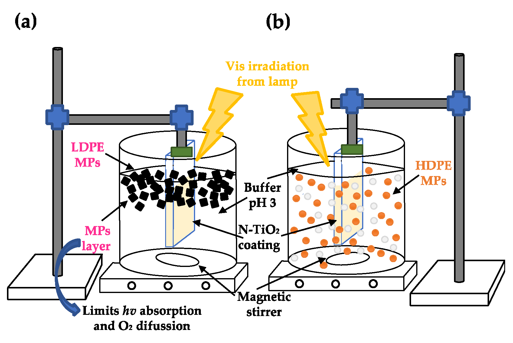
2.3. Photocatalytic Tests

Photocatalysis in aqueous medium was designed to test the remediation of water contaminated with MPs, even when the interaction between the MPs and the N–TiO2 coating was limited. HDPE and LDPE plastics are resistant to visible-light degradation, while having poor UV resistance [42]. If exposed to UV irradiation, photo-oxidation contributes to the overall MP degradation process [43]. Thus, photocatalytic tests were performed using visible light to avoid UV-derived plastic degradation and misinterpretations of the data. The tests were conducted at pH 3, as a previous study revealed that this pH favors the photocatalytic degradation of HDPE MPs using C,N–TiO2 powders [30]. For each MP, 200 mg of the plastic were added to a glass container with 50 mL of a CH3COONa/CH3COOH buffer (pH 3). This led to a concentration of 0.4 wt/v% of MP dispersion. The N–TiO2 coating was then immersed in the MP dispersion, and the container was transferred to a closed reaction chamber equipped with a 50 W Visible LED Lamp (400–800 nm) and a stirring plate. The dispersion was kept at 215 mm from the lamp. Photocatalysis was performed at room temperature for 50 h with continuous stirring at 300 rpm. Photolysis tests were also carried out with an N–TiO2-free glass substrate. All photolysis and photocatalytic tests were performed in duplicate.
Photocatalytic degradation of plastics is usually followed by mass loss [44,45,46], as degradation leads to the formation of low-molecular-weight oxidation products that are released from the polymer to the surrounding medium [43,47,48]. Thus, degradation was followed by monitoring the mass losses of the MPs after regular irradiation intervals using a HR-200 Analytical Balance (A&D, San Jose, CA, USA) with 0.1 mg resolution. Mass loss was calculated using the following Equation (6):
Mass loss (%) = [(M0 − M)/M0] × 100
where M0 is the initial mass of the MPs and M is the mass at t hours of irradiation. The differences between means were tested using t-test in a significance level of α = 0.05 using Statistica Software V10.

3. Results and Discussion

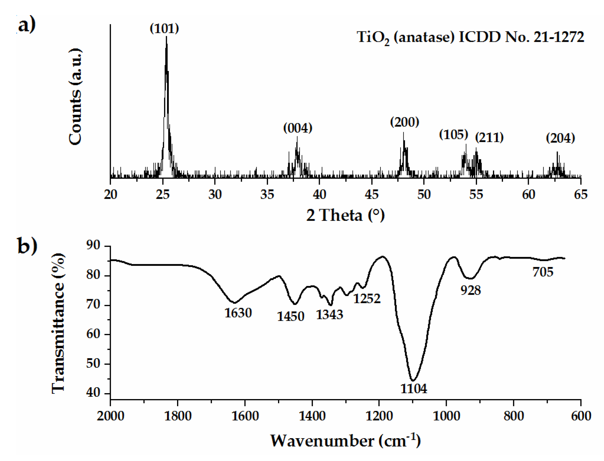
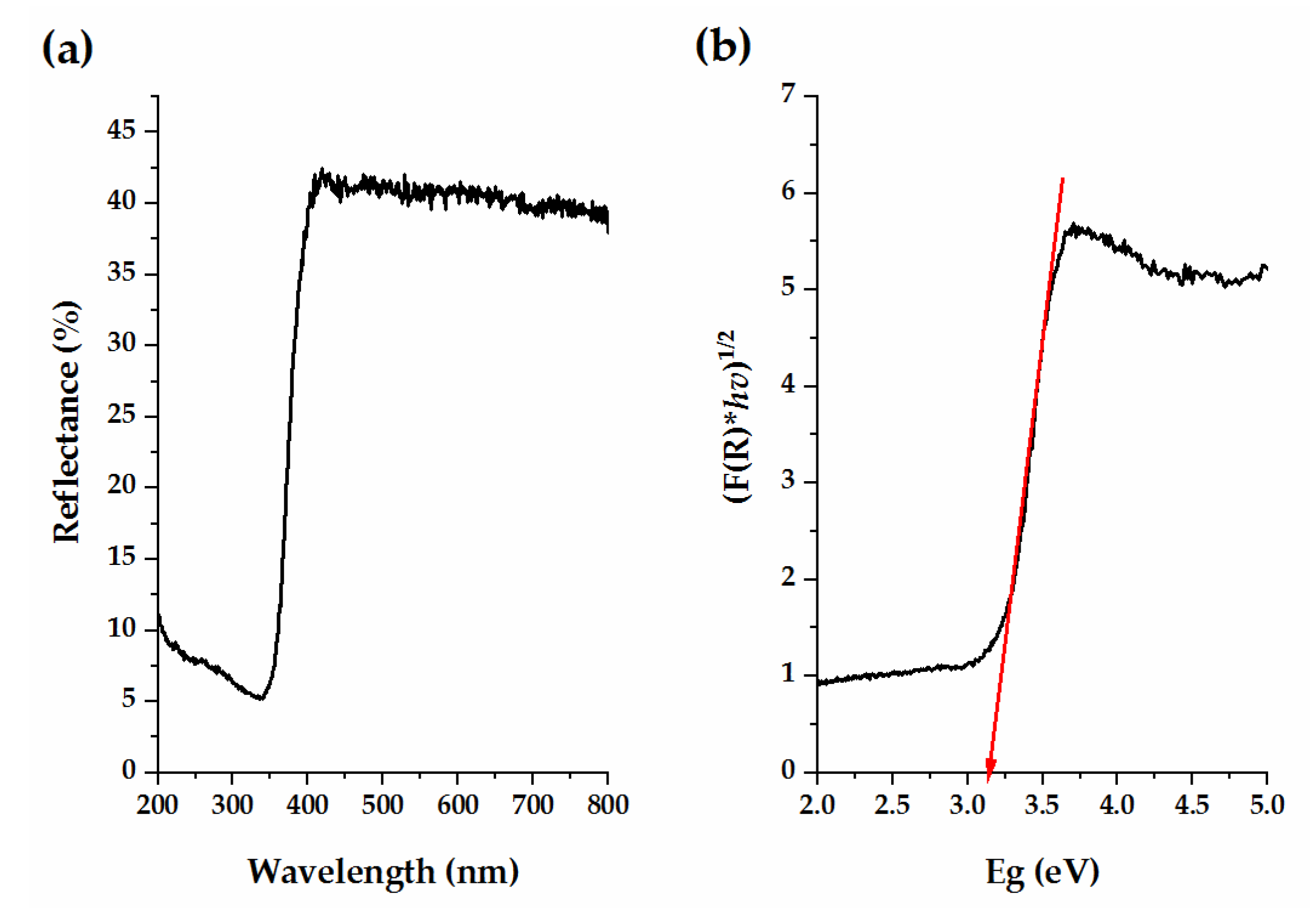
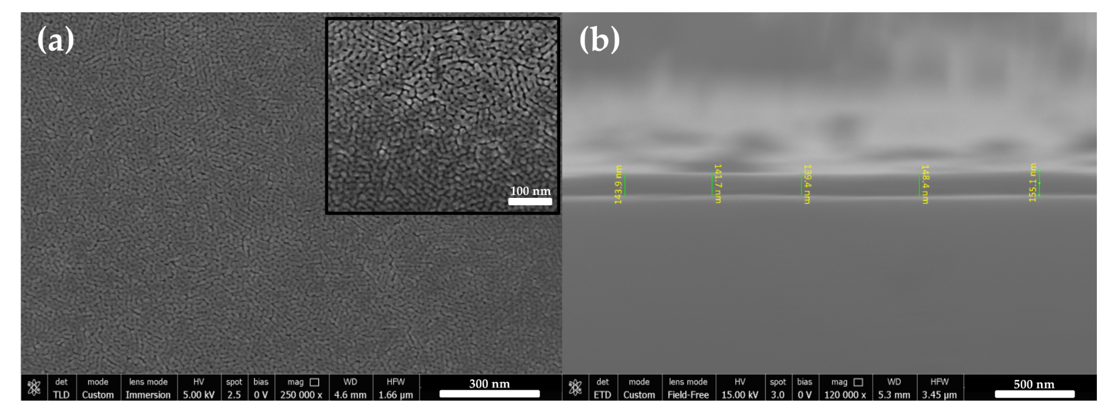
3.1. N–TiO2 Coating Characterization

Figure 1a presents the XRD pattern of the N–TiO2 coating that was composed by the anatase TiO2, known for its high photocatalytic activity [49]. X-ray structural analysis of the samples did not show any detectable dopant-related peak [39]. Figure 1b shows the ATR-FTIR spectrum of the coating. The bands observed in the range of 1000–600 cm−1 correspond to the Ti–O and Ti–O–Ti stretching vibrations of TiO2 [50]. The band at 1630 cm−1 corresponds to the stretching and bending vibration of water and O–H groups adsorbed in the surface of the photocatalyst [50,51,52]. Bands around 1450, 1340, 1252, and 1104 cm−1 were attributed to the vibrations of the N–Ti–O and Ti–O–N bonds [39,51,52], suggesting that the N species were successfully incorporated into the TiO2 lattice.
Further confirmation of nitrogen doping was revealed from analysis of the diffuse-reflectance spectrum of the N–TiO2 sample (Figure 2a). The spectrum was transformed using the Kubelka–Munk function, and the band-gap value was obtained from the plot presented in Figure 2b. The N–TiO2 sample presented an Eg value of 3.1 eV. Although this value was not distant from the Eg of commercial TiO2 (3.2 eV [23]), it allowed the absorption of light to the N–TiO2 material with a wavelength of 400 nm, i.e., inside of the visible range of the light spectrum.
Figure 3 displays the FEG-SEM micrographs of the N–TiO2 coating that was uniformly distributed over the glass substrate.
Figure 3 shows that the N–TiO2 coating presented the microstructure and uniform porosity typically reported for TiO2 mesoporous coatings [34], as well as a thickness of 146 ± 3 nm. The inset of Figure 3a shows that the coating had a grid-like structure composed of nanoparticles of 12 ± 3 nm and pores with a diameter of approximately 10 nm. The presence of homogeneously distributed porosity was due to the use of the Pluronic F127 copolymer as a pore-forming agent during the synthesis procedure, which led to a fully accessible network [34]. This porosity is usually associated with a high surface area, as confirmed by its BET surface area of 74.7 ± 0.2 m2/g. This value was higher than that reported for Degussa P25 TiO2 (50 m2/g) [31].

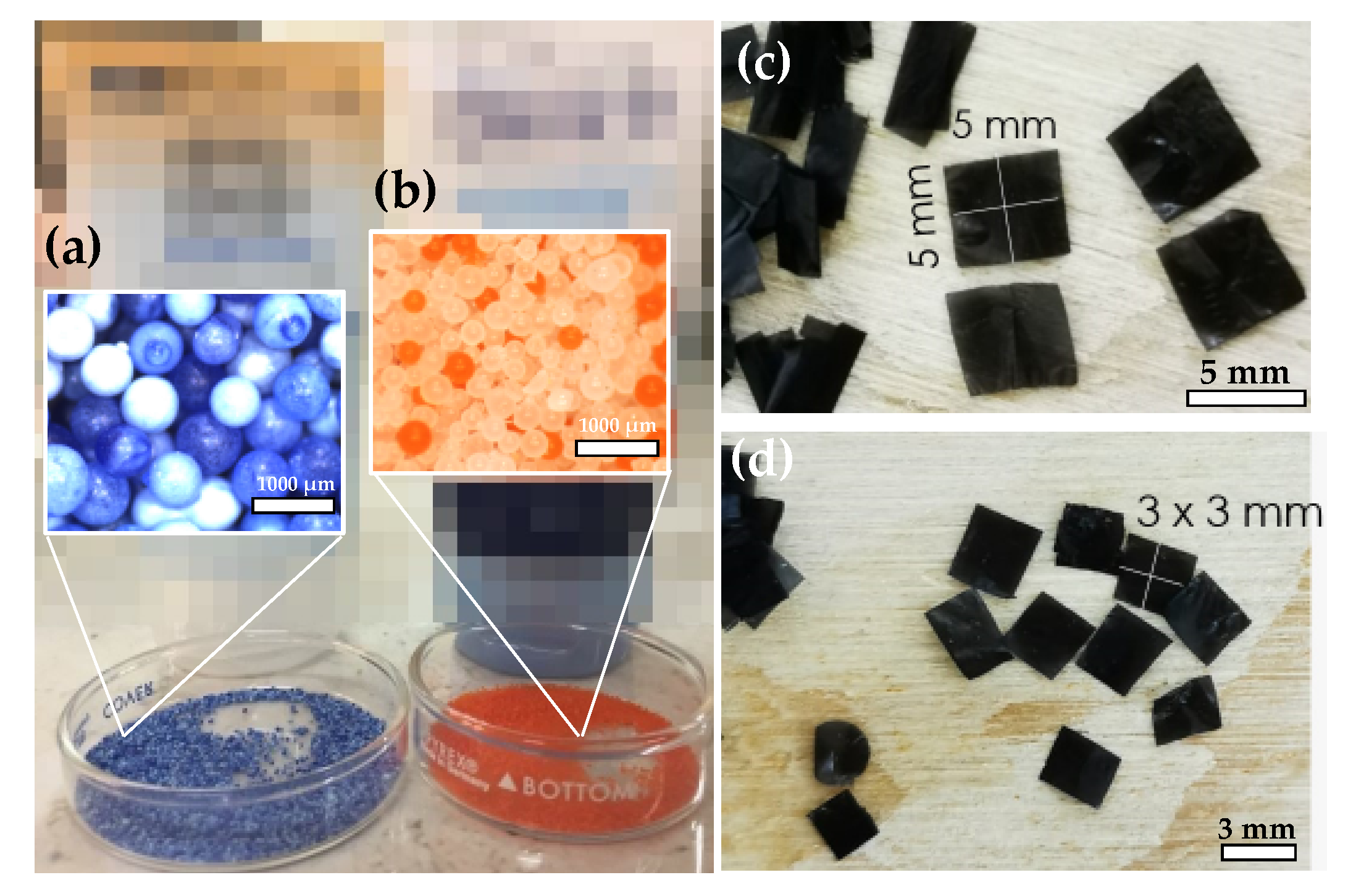
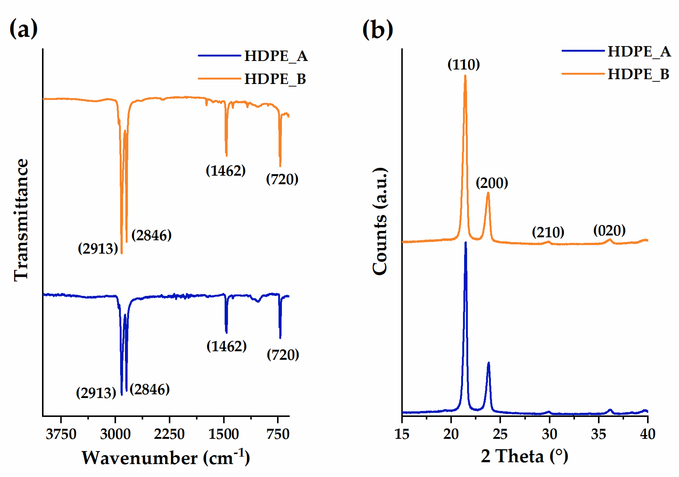
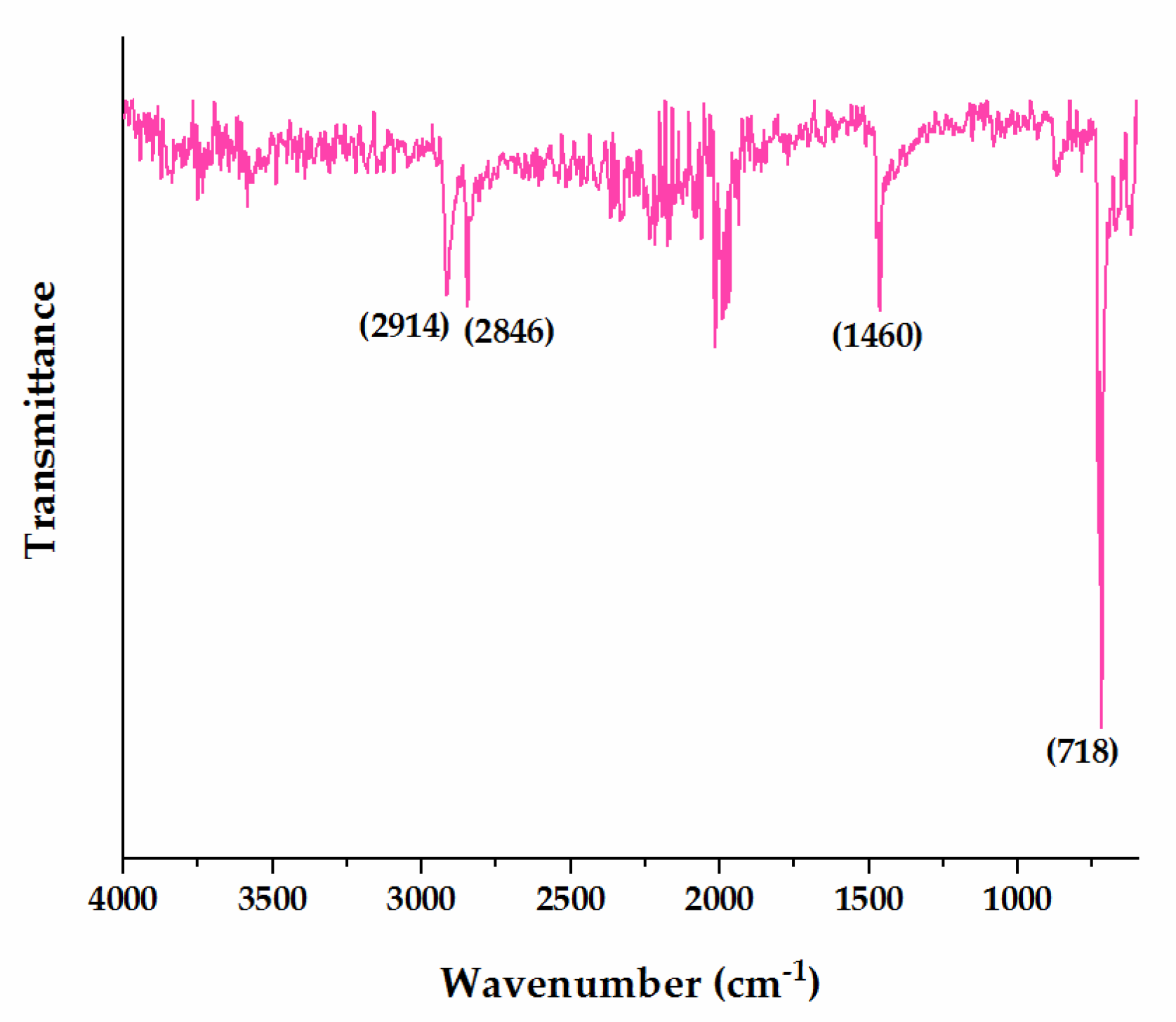
3.2. Microplastic Characterization

Figure 4a,b displays the optical micrographs of the primary spherical MPs extracted from the facial scrubs. The blue microbeads extracted from Scrub A had a mean particle size of 814 ± 91 μm, while the orange and white microbeads extracted from Scrub B were smaller, with a mean particle size of 382 ± 154 μm.
Figure 4c,d shows the size and shape of secondary MP films obtained from the LDPE plastic bag. The bigger size (5 mm × 5 mm) was chosen because it fit well with the largest-size limit of the MP definition (≤5 mm). The smaller size (3 mm × 3 mm) was chosen because it was the smallest particle size of secondary MPs that could be obtained and experimentally reproduced.
Figure 5a presents the ATR-FTIR spectra of the microbeads extracted from the commercial facial scrubs. Both samples presented the same spectrum. Bands at 2913, 1462 and 720 cm−1 were due to the CH stretching, deformation and rocking vibrations [50], while the band at 2846 cm−1 corresponded to the symmetric stretching mode of CH2 [27]. All those bands were attributed to the alkyl chains of HDPE. Figure 5b presents the XRD patterns of both samples with reflection peaks at 2θ values of 20°, 24°, 30° and 36°. These peaks corresponded to the (110), (200), (210) and (020) reflection planes of HDPE [53].
Figure 6 presents the ATR-FTIR spectrum of the LDPE bag that was used as a source of the secondary MPs. As in the case of HDPE, the bands were attributed to the alkyl chains of PE [27,50]. Bands in the 2100–2000 cm−1 range could be attributed to organic chemical additives of commercial LDPE plastics [54]. The band at 720 cm−1 can correspond not only to the rocking vibration of the CH bonds of LDPE polymer [27,50] but also to those of the organic additives [54]. As the commercial bag supplier clearly stated that the bags were composed of LDPE, the composition of the LDPE MPs was only confirmed by ATR-FTIR.

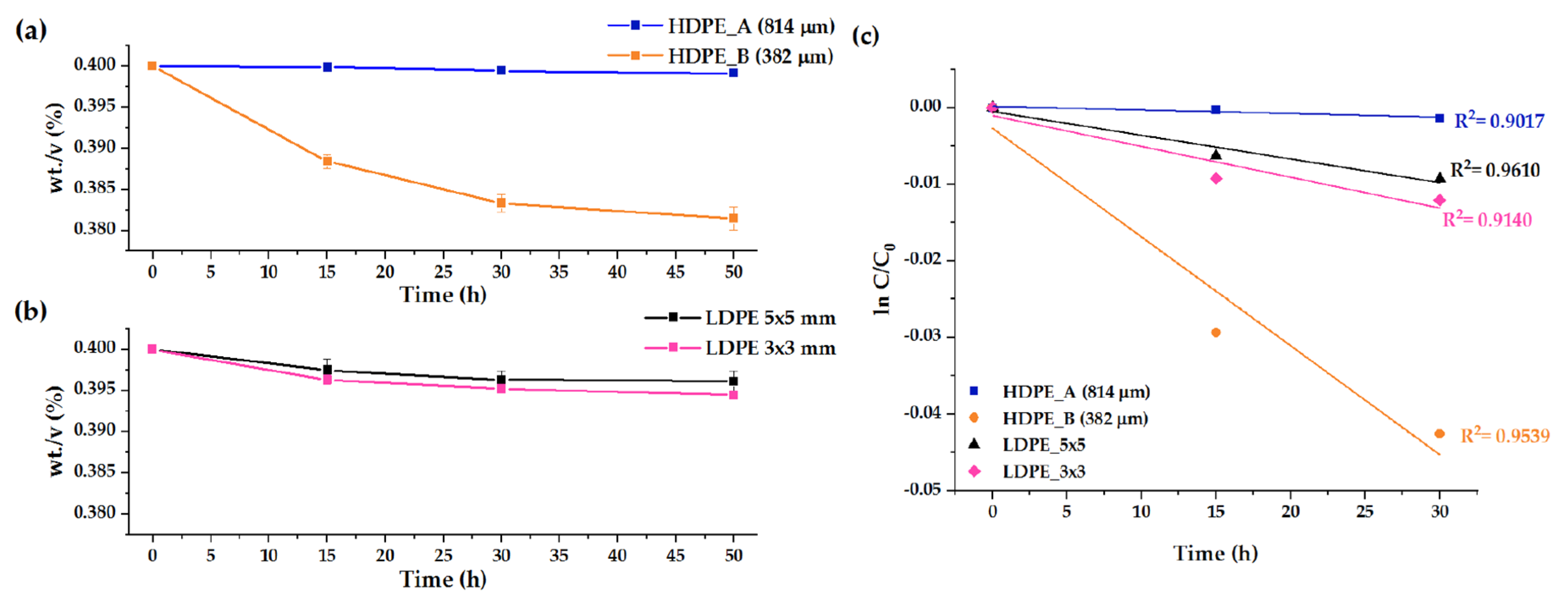
3.3. Microplastic Photocatalytic Degradation by N–TiO2

As observed in Figure 4, the four tested MPs present color. Photolysis experiments were performed in visible light to determine whether the MPs presented photoinitiated oxidative degradation due to the presence of chromophores. PE does not contain unsaturated double bonds that absorb light energy during the initiation step of photoinitiated oxidative degradation, and it is thus expected to be immune to this phenomenon [55]. However, the presence of inherent chromophoric groups could promote photoinitiated degradation to some extent [28,48,55].
Figure 7a presents the results of the photolysis tests. For all samples, there were not significant mass losses during the whole irradiation interval, as presented in Table 1. These results suggest that the chromophores of the HDPE and LDPE MPs did not promote their photodegradation. The results presented in Figure 7a also confirm the high durability of HDPE and LDPE plastics in an acid medium [56]. Additionally, it was found that collisions between the MPs and the clean glass substrate did not promote mass loss of the plastics due to mechanical action.
Figure 7b presents the mass loss vs. time plots for HDPE MPs derived from the A and B facial scrubs. There was an effect of particle size in the photocatalytic process.
For the biggest HDPE_A MPs, the blue curve shows that mass loss after 50 h of irradiation was very limited, with a mean value of 0.22% (0.02 SE). This result was explained by the intrinsic characteristics of the MPs. HDPE was not soluble in the reaction medium, and the particle size of this sample was huge compared with the particles or pores of N–TiO2 (67.8 × 10³ times larger). These characteristics prevented the adsorption of the HDPE_A MPs on the semiconductor, explaining their limited mass loss.
In the case of HDPE MPs derived from Scrub B, they were 31.8 × 10³ times larger than N–TiO2 particles, and adsorption of these plastics on the semiconductor surface was not possible. However, the orange curve of Figure 7b shows that, after 50 h of irradiation, a total mass loss of 4.65% (0.35 SE) was achieved. This value was higher than mass loss obtained in the bioremediation of PE MPs using Bacillus cereus and Bacillus gottheilii (0% mass loss in two days for both organisms) [15]. It was also higher than the degradation obtained with PE/semiconductor composite systems such as PE/dye-sensitized TiO2 nanotubes (0% mass loss in two days) [48] and PE/goethite (1.74% mass loss in 50 h) [43].
Mass loss obtained for HDPE_B MPs was related to two factors. The first was the continuous stirring that favors collisions between dispersed MPs and surface-bound ROS of the N–TiO2 coating [31]. This phenomenon may lead to the degradation of the more external surface of the plastics [30,55]. The second factor was the mobility of the OH• and O2• radicals in the aqueous medium [26,31]. Even when the photocatalytic degradation of pollutants is usually attributed to the attack by surface-bound ROS, there is increasing evidence that these species are mobile and able to migrate from the surface of TiO2 into the solid or liquid reaction medium [26,31,35,36,37]. Thus, the observed mass loss for the HDPE_B sample was also attributed to the desorption of the ROS from the active sites of N–TiO2 and their diffusion into the solution’s bulk, where they could attack the dispersed MPs. In this phenomenon, the high surface area and microstructure of the mesoporous N–TiO2 coating played an essential role. The high surface area of the N–TiO2 coating allowed high availability of active sites where high quantities of ROS could be formed [34]. The presence of homogeneously distributed porosity led to a fully accessible network that allowed the ROS to easily diffuse to the bulk solution (Figure 3). Both phenomena, collision of the MPs with the N–TiO2 surface-bound ROS and radical migration, cannot proceed without the presence of the semiconductor, as shown in the photolysis experiments of Figure 7a.
The previous explanation suggests that, at the tested conditions, HDPE_A MPs should also interact with the ROS in both the bulk of the solution and the surface of N–TiO2. However, the mass-loss values presented in Figure 7b show that the MP particle size influenced the degradation process. Mass loss was higher for smaller plastic particles. By halving the size of the HDPE MPs, the degradation process was favored, and the final mass loss increased 21 times. This behavior was related to the increase of the surface-to-volume ratio of the MPs as their particle size decreased [55]. As photocatalysis of plastics was carried out by the interaction of the TiO2-derived ROS with the surface of the plastics, HDPE_B MPs with the higher surface area better interacted with these radicals, leading to higher degradation than that obtained for HDPE_A MPs.
It has been established that leaching of residual monomers and oligomers from plastics can affect the interpretation of their degradation data [57]. If leaching from plastics takes place during the reaction, mass loss due to photocatalysis could be overestimated. Here, it was considered that leaching should equally occur during photolysis and photocatalysis, as the abiotic factors that may cause it—if any—were present in both processes. As observed in Figure 7a, there were no significant mass losses during photolysis. On the other hand, Figure 7b,c shows that mass losses were registered in the photocatalytic experiments. Thus, it was considered that leaching does not take place in the time scale of the experiments or it is too low to be detected by mass loss. The results presented in Figure 7a also suggest that the chemical differences between HDPE_A and small HDPE_B MP (pigmentation additives) do not influence mass loss. Further investigation of the reaction filtrates by analytical techniques such as GC-MS should be performed to determine if leaching of MPs takes place during photocatalysis. For example, Björnsdotter (2015) reported that aliphatic hydrocarbons in the size of C14-C22 were leached out from 500 mg of HDPE MPs in artificial seawater in the concentration range 0.47 × 10⁻³–1.13 × 10⁻³ μg/mL within 24 h [58]. The released monomers and oligomers can be degraded by photocatalysis, as a wide variety of aliphatic compounds have been mineralized by several photocatalytic semiconductors [23,24,25].
The mechanism generally reported for PE photoinitiated oxidative degradation is presented in Equations (7)–(11):
(–CH2CH2–)n + OH• → (–•CHCH2–)n + H2O
(–•CHCH2–)n + O2 → (–CH2–HCOO•–CH2)n
(–CH2–HCOO•–CH2)n + (–CH2CH2–)n → (–CH2–HCOOH–CH2-)n + (–•CHCH2–)n
(–CH2–HCOOH–CH2–)n → (–CH2–HCO•–CH2–)n + OH•
(–CH2–HCO•–CH2–)n + (–CH2CH2–)n → (–•CHCH2–)n + (–CH2–HCOH–CH2–)n
In the initiation step, the photogenerated hydroxyl radicals break the C–H bonds on the polymer backbone and generate polyethylene alkyl radicals (Equation (7)) [28,55]. During propagation, an alkyl radical reacts with oxygen to form a peroxy radical (Equation (8)) that abstracts a hydrogen atom from another polymer chain to form the hydroperoxide species (Equation (9)). The hydroperoxide is further cleavage into two new free oxy and hydroxyl radicals by the scission of the weak O–O bond (Equation (10)) [59,60]. Besides the formation of hydroperoxides, further complex radical reactions take place that lead to autoxidation. The propagation step ultimately leads to chain scission or crosslinking, leading to a decrease or increase in molecular weight, respectively. Lastly, termination of the radical reaction takes place when the combination of two radicals generates inert products such as alkenes, aldehydes and ketones. For PE, auto-oxidation leads to the formation of oxygenated low-molecular-weight fragments such as aliphatic carboxylic acids, alcohols, aldehydes and ketones [55]. Some of the above compounds should be susceptible to photoinitiated degradation because of their unsaturated double bonds [55].
The PE degradation mechanism illustrated in Reactions (7)–(11) shows that each initiating polyethylene alkyl radical produces two new free radicals through the decomposition of hydroperoxide. Since the formation of the initiating radical depends on the reaction of the photogenerated hydroxyl radicals with the polymer, the mass loss reported in Figure 7b reveals that the degradation reaction was promoted by a combination of the factors involved in the reaction system: (i) the high availability of hydroxyl radicals derived from the high surface area of the N–TiO2 coating; (ii) the interaction of surface-bounded and bulk hydroxyl radicals with HDPE MPs by radical diffusion; and (iii) the high surface-to-volume ratio of the small HDPE_B MPs. Furthermore, the reported mechanism explains why photolysis did not promote plastic degradation due to the absence of the N–TiO2-derived hydroxyl radicals.
Figure 7c presents the mass loss vs. time plots for the LDPE MPs derived from the plastic bag. The black and pink curves show mass losses of 0.97% (0.32 SE) and 1.38% 0.13 SE) for the LDPE_5 mm × 5 mm and LDPE_3 mm × 3 mm MPs, respectively. These mass losses were attributed to the interaction of the plastic particles with the ROS radicals in both the bulk of the solution and the surface of N–TiO2, and the effect of particle size on the photocatalytic mass-loss process of LDPE MPs was much smaller than that observed for HDPE MPs (just 1.4 times that obtained for the bigger ones). The limited mass losses obtained for the film-shaped LDPE MPs were principally related to their particular shapes. Densities of LDPE and HDPE were 0.91–0.94 and 0.95–0.97 g/cm3, respectively [61]. These values were lower than that of the aqueous buffer solution (1.0 g/cm3) and favored the floating of the MPs. During the photocatalytic experiments, stirring resulted in the dispersion of the spherical HDPE MPs in the whole buffer solution, and the buoyant characteristics of HDPE did not interfere with the experiment. On the other hand, stirring did not promote the dispersion of the film-shaped MPs in the whole buffer solution. Instead, stirring induced the accumulation of the buoyant LDPE MPs films in the liquid–gas interface of the reaction system, and a layer of MPs was formed (both situations are presented in Figure 8).
The LDPE MP layer may have promoted two undesirable effects: (i) it could hinder the absorption of light by the N–TiO2 coating immersed in the buffer; and (ii) it could decrease the diffusion of oxygen from the air into the liquid phase. Both factors are of fundamental importance for carrying out photocatalysis. The absorption of light photons by the N–TiO2 is needed to generate the eh+ pairs (see Equation (1)). Oxygen molecules help to avoid their recombination as well as react with the photogenerated e to form the superoxide anion radical (see Equation (3)). Furthermore, as oxygen is incorporated into the polymers during photo-oxidation, its presence is essential during this process (see Equation (8)). The spherical-shaped MPs did not accumulate into any “barrier-layer” similar to that formed by the film-shaped MPs. Then, the differences in the mass losses obtained for LDPE and HDPE MPs revealed that, even if both MPs were buoyant in water, their particular shape ruled their capacity of dispersion in the aqueous medium, and, consequently, influenced their degradation by hindering or allowing light and oxygen diffusion into the reaction system.
It is important to highlight that the differences in the obtained mass loss values between the spherical-shaped HDPE and film-shaped LDPE MPs could also be related to the inherent characteristics of each MP (i.e., polymer composition, additives, color or presence of porosity). However, MPs are frequently present in aquatic and terrestrial environments as mixtures of different polymers, sizes, shapes and colors [62]. These mixtures can hardly be separated and, although the effect of those factors may be significant in the specific degradation paths of each MP type, the designing of a specific degradation process for each MP may have limited practical application, as MPs cannot be separated before being treated by photocatalysis or other remediation proposals.
The mass-loss values reported in Figure 7b,c were expressed as concentration in order to evaluate the kinetics of photocatalytic degradation. Figure 9a,b presents the degradation plots of the HDPE and LDPE MPs in terms of concentration, which decreases in a smooth exponential curve over time, a trend that corresponded to a first-order reaction. Thus, data presented in Figure 9a,b were fitted to a first-order model using Equation (12):
C = C0·ekt
where C0 is the initial concentration of the MPs, C is the concentration at time t and k is the first-order rate constant [48]. Rate constants were obtained by plotting ln C/C0 in the function of time, as presented in Figure 9c.
The values of k (expressed as k/1 × 104) are presented in Table 2. In the same table, MP shape, size and mass loss obtained after photocatalytic degradation are presented for a quick reference.
Table 2 confirms the previously discussed trends. For each polymer, higher k values were obtained for smaller particle sizes, and the positive effect of increasing the surface-to-volume ratio of the MPs was evident. The effect of MP shape was also confirmed by the k values that were obtained for the film-shaped MPs. It is expected that, as photocatalysis proceeds, the MPs will fragment and degrade quickly due to their smaller size, assuming that the N–TiO2 coating maintains its activity over time (i.e., it is not poisoned by the eventual oxidation products other than CO2 and H2O). However, further investigation is needed to confirm this assumption.
The carbonyl index (CI) was calculated to confirm degradation. The CI is commonly used to quantify the degree of chemical oxidation of polyolefins, such as polyethylene [47], and is defined as the ratio of absorbance of the carbonyl group around 1710 cm−1 to an internal thickness band as reference peak at 1380 cm−1 [48] (Equation (13)):
Carbonyl index (CI) = A1710/A1380
Table 3 shows the CI values of all the MPs before (CI0h) and after photocatalytic degradation by the mesoporous N–TiO2 coating (CI50h). Only the HDPE_B sample presented a CI50h value that was 6.4 times the CI0h. This result confirms that the combination of small plastic particles (with a high surface area) and adequate particle shape (i.e., one that favors light adsorption by the coating and O2 diffusion into the reaction system) leads to higher degradation. In the case of the HDPE_A and LDPE MPs, the absence of changes in the CI was related to the low degradation of these samples. Although CI measurements are often related to plastic oxidative degradation, the measurement of IR absorbance of the carbonyl band is not appropriate in the very first stages of degradation [47], as there is a non-negligible part of low-molecular-weight oxidation products that are lost by migration from the polymer to the surrounding atmosphere [43,47,48]. Thus, the low mass losses and the constant CI values of these samples suggested that the large spherical HDPE and film-shaped LDPE MPs may have been in the first stages of their photocatalytic degradation during the 50 h of irradiation.
The partial photodegradation of PE plastics leads to the formation volatile organic compounds (VOCs). Lomonaco et al. found that the photodegradation of HDPE and LDPE MPs after artificial ageing at 40 °C and 750 W/m2 for four weeks led to the release of VOCs such as carboxylic acids, esters, lactones, ketones, aldehydes, alcohols, ethers, alkanes and alkenes [63]. Other studies where the degradation of PE MPs was promoted by advanced oxidation processes (AOPs) involving ROS found that organic intermediates from degradation include alkanes, alkenes, alcohols, ketones, aldehydes, carboxylic acids, lactones and esters [22,28,64,65].
The magnitude and direction of the effects of the partial-oxidation products from PE degradation depend on their concentration, exposure conditions and the organisms to which they are exposed. Loh et al. found that 1,3-butadiene and formaldehyde are hazardous organic air pollutants that represent a high cancer risk for humans [66]. Menicagli et al. reported that leachates derived from pristine PE bags and those exposed to beach and marine conditions positively influenced the early growth of Glaucium flavum seedlings, but caused seedling anomalies in the same coastal-dune plants and in Thinopyrum junceum [67]. Kang et al. (2019) [22] experimentally demonstrated that a mixture of alkanes, alkenes, ketones, alcohols, aldehydes, mono-/dicarboxylic acids, lactones ketoacids and esters derived from the degradation of HDPE MPs by hydrothermal carbocatalytic oxidation (driven by SO4• and OH•) was environmentally benign for green alga C. vulgaris, and it could serve as a carbon source for algae cultivation [22]. Lastly, it was reported that microorganisms can attack PE with molecular weight < 500 Da at any terminal methyl group [55]. Thus, smaller polymer fragments produced by an incomplete photocatalytic reaction can be biodegraded to shorter segments such as esters and acids. After enzymatic action humus, CO2 and H2O are the ultimate products [55].
Although in this work reaction filtrates after photocatalysis were not analyzed to determine the oxidation products, it is likely that the reaction intermediates listed above could be generated in any other degradation process of PE driven by hydroxyl radicals. In the photocatalytic system studied here, HDPE MPs were degraded by the OH• that was generated by the irradiation of the mesoporous N–TiO2 with light. This was demonstrated by Vital-Grappin et al. [68]. By the use of tert-butanol reagent as an OH• scavenger, the authors investigated the effect of the OH• on the degradation of the same scrub-derived HDPE MPs studied here using a mesoporous visible-active N–TiO2 semiconductor [68]. In their experiments, the authors found that, when the OH• was present in the reaction medium, degradation of the MPs was promoted, as high mass losses were obtained after 50 h of visible light irradiation. On the other hand, when the OH• was scavenged by tert-butanol, no mass loss was registered after the same irradiation time, indicating that degradation could not be carried out without their presence. Thus, it could be expected that the eventual reaction intermediates that were preferably formed during the HDPE MP oxidation by OH• in our system were nontoxic to aquatic microorganisms.

4. Conclusions

In this work, some first insights of the photocatalytic degradation of HDPE and LDPE MPs in visible light and using mesoporous N–TiO2 coating are presented. First, it was found that photocatalysis of MPs with a potential application in WWTPs is possible, although some operational parameters such as MP particle size and shape should be considered for the design of effective and fast processes. This is of great importance due to the intrinsic characteristics of this kind of emerging pollutant. The results shown here support the hypothesis that the degradation of HDPE and LDPE is affected by a combination of the factors involved in the reaction system: (i) the high availability of OH• derived from the high surface area of the coating; (ii) the interaction of bulk and surface-bounded OH• with the MPs by radical diffusion and stirring; (iii) the high surface-to-volume ratio of the smaller MPs; and (iv) the shape of the MPs that could lead to a very well or poorly illuminated and oxygenated reaction medium.

Author Contributions

Conceptualization, E.I.C.-G.; methodology, E.I.C.-G. and B.E.L.-G.; investigation, B.E.L.-G.; resources, E.I.C.-G., J.M.H.-L., A.A.Z.-C. and C.S.; writing—original draft, E.I.C.-G.; writing—review and editing, E.I.C.-G., J.M.H.-L., A.A.Z.-C. and C.S.; supervision, E.I.C.-G. and C.S.; project administration, E.I.C.-G.; and funding acquisition, E.I.C.-G. All authors have read and agreed to the published version of the manuscript.

Funding

This research was funded by the Consejo Nacional de Ciencia y Tecnología (CONACYT), grant number APN-2017/5167.

Acknowledgments

The authors thank Paola Miselli and Massimo Tonelli from Università degli Studi di Modena e Reggio Emilia for their technical support with the XRD and FEG-SEM analysis. B.E.L.-G. acknowledges CONACYT for financial support (scholarship) during the preparation of this work.

Conflicts of Interest

The authors declare no conflict of interest. The funders had no role in the design of the study; in the collection, analyses, or interpretation of data; in the writing of the manuscript, or in the decision to publish the results.

References

  1. Paul-Pont, I.; Tallec, K.; Gonzalez-Fernandez, C.; Lambert, C.; Vincent, D.; Mazurais, D.; Zambonino-Infante, J.L.; Brotons, G.; Lagarde, F.; Fabioux, C.; et al. Constraints and priorities for conducting experimental exposures of marine organisms to microplastics. Front. Mar. Sci. 2018, 5, 252. [Google Scholar] [CrossRef]
  2. Koelmans, A.A.; Mohamed Nor, N.H.; Hermsen, E.; Kooi, M.; Mintenig, S.M.; De France, J. Microplastics in freshwaters and drinking water: Critical review and assessment of data quality. Water Res. 2019, 155, 410–422. [Google Scholar] [CrossRef]
  3. Dris, R.; Gasperi, J.; Mirande, C.; Mandin, C.; Guerrouache, M.; Langlois, V.; Tassin, B. A first overview of textile fibers, including microplastics, in indoor and outdoor environments. Environ. Pollut. 2017, 221, 453–458. [Google Scholar] [CrossRef] [Green Version]
  4. Obbard, R.W.; Sadri, S.; Wong, Y.Q.; Khitun, A.A.; Baker, I.; Thompson, R.C. Global warming releases microplastic legacy frozen in Arctic Sea ice. Earth’s Futur. 2014, 2, 315–320. [Google Scholar] [CrossRef]
  5. Sol, D.; Laca, A.; Laca, A.; Díaz, M. Approaching the environmental problem of microplastics: Importance of WWTP treatments. Sci. Total Environ. 2020, 140016. [Google Scholar] [CrossRef]
  6. Gong, J.; Xie, P. Research progress in sources, analytical methods, eco-environmental effects, and control measures of microplastics. Chemosphere 2020, 254, 126790. [Google Scholar] [CrossRef]
  7. Wong, J.K.H.; Lee, K.K.; Tang, K.H.D.; Yap, P.S. Microplastics in the freshwater and terrestrial environments: Prevalence, fates, impacts and sustainable solutions. Sci. Total Environ. 2020, 719, 137512. [Google Scholar] [CrossRef]
  8. Hantoro, I.; Löhr, A.J.; Van Belleghem, F.G.A.J.; Widianarko, B.; Ragas, A.M.J. Microplastics in coastal areas and seafood: Implications for food safety. Food Addit. Contam. Part A 2019, 36, 674–711. [Google Scholar] [CrossRef]
  9. Peixoto, D.; Pinheiro, C.; Amorim, J.; Oliva-Teles, L.; Guilhermino, L.; Vieira, M.N. Microplastic pollution in commercial salt for human consumption: A review. Estuar. Coast. Shelf Sci. 2019, 219, 161–168. [Google Scholar] [CrossRef]
  10. Schwabl, P.; Liebmann, B.; Köppel, S.; Königshofer, P.; Bucsics, T.; Trauner, M.; Reiberger, T. Assessment of Microplastic Concentrations in Human Stool—Preliminary Results of a Prospective Study. 2018. Available online: https://www.ncbi.nlm.nih.gov/pmc/articles/PMC6796240 (accessed on 8 July 2020).
  11. Cox, K.D.; Covernton, G.A.; Davies, H.L.; Dower, J.F.; Juanes, F.; Dudas, S.E. Human consumption of microplastics. Environ. Sci. Technol. 2019, 53, 7068–7074. [Google Scholar] [CrossRef] [Green Version]
  12. Revel, M.; Châtel, A.; Mouneyrac, C. Micro (nano) plastics: A threat to human health? Curr. Opin. Environ. Sci. Heal. 2018, 1, 17–23. [Google Scholar] [CrossRef]
  13. Napper, I.E.; Thompson, R.C. Environmental deterioration of biodegradable, oxo-biodegradable, compostable, and conventional plastic carrier bags in the sea, soil, and open-air over a 3-year period. Environ. Sci. Technol. 2019, 53, 4775–4783. [Google Scholar] [CrossRef] [PubMed]
  14. Markowicz, F.; Szymańska-Pulikowska, A. Analysis of the possibility of environmental pollution by composted biodegradable and oxobiodegradable plastics. Geoscience 2019, 9, 460. [Google Scholar] [CrossRef] [Green Version]
  15. Auta, H.S.; Emenike, C.U.; Fauziah, S.H. Screening of Bacillus strains isolated from mangrove ecosystems in Peninsular Malaysia for microplastic degradation. Environ. Pollut. 2017, 231, 1552–1559. [Google Scholar] [CrossRef] [PubMed]
  16. Paço, A.; Duarte, K.; da Costa, J.P.; Santos, P.S.M.; Pereira, R.; Pereira, M.E.; Freitas, A.C.; Duarte, A.C.; Rocha-Santos, T.A.P. Biodegradation of polyethylene microplastics by the marine fungus Zalerion maritimum. Sci. Total Environ. 2017, 586, 10–15. [Google Scholar] [CrossRef]
  17. Huerta Lwanga, E.; Thapa, B.; Yang, X.; Gertsen, H.; Salánki, T.; Geissen, V.; Garbeva, P. Decay of low-density polyethylene by bacteria extracted from earthworm’s guts: A potential for soil restoration. Sci. Total Environ. 2018, 624, 753–757. [Google Scholar] [CrossRef] [PubMed]
  18. Zhang, J.; Gao, D.; Li, Q.; Zhao, Y.; Li, L.; Lin, H.; Bi, Q.; Zhao, Y. Biodegradation of polyethylene microplastic particles by the fungus Aspergillus flavus from the guts of wax moth Galleria mellonella. Sci. Total Environ. 2020, 704, 135931. [Google Scholar] [CrossRef] [PubMed]
  19. Talvitie, J.; Mikola, A.; Setälä, O.; Heinonen, M.; Koistinen, A. How well is microlitter purified from wastewater?—A detailed study on the stepwise removal of microlitter in a tertiary level wastewater treatment plant. Water Res. 2017, 109, 164–172. [Google Scholar] [CrossRef] [Green Version]
  20. Enfrin, M.; Dumée, L.F.; Lee, J. Nano/microplastics in water and wastewater treatment processes—Origin, impact and potential solutions. Water Res. 2019, 161, 621–638. [Google Scholar] [CrossRef]
  21. Miao, F.; Liu, Y.; Gao, M.; Yu, X.; Xiao, P.; Wang, M.; Wang, S.; Wang, X. Degradation of polyvinyl chloride microplastics via an electro-Fenton-like system with a TiO2/graphite cathode. J. Hazard. Mater. 2020, 123023. [Google Scholar] [CrossRef]
  22. Kang, J.; Zhou, L.; Duan, X.; Sun, H.; Ao, Z.; Wang, S. Degradation of cosmetic microplastics via functionalized carbon nanosprings. Matter 2019, 1, 745–758. [Google Scholar] [CrossRef] [Green Version]
  23. Pant, B.; Park, M.; Park, S.J. Recent advances in TiO2 films prepared by sol-gel methods for photocatalytic degradation of organic pollutants and antibacterial activities. Coatings 2019, 9, 613. [Google Scholar] [CrossRef] [Green Version]
  24. Aziz, K.H.H.; Omer, K.M.; Mahyar, A.; Miessner, H.; Mueller, S.; Moeller, D. Application of photocatalytic falling film reactor to elucidate the degradation pathways of pharmaceutical diclofenac and ibuprofen in aqueous solutions. Coatings 2019, 9, 465. [Google Scholar] [CrossRef] [Green Version]
  25. Moreira, N.F.F.; Narciso-da-Rocha, C.; Polo-López, M.I.; Pastrana-Martínez, L.M.; Faria, J.L.; Manaia, C.M.; Fernández-Ibáñez, P.; Nunes, O.C.; Silva, A.M.T. Solar treatment (H2O2, TiO2-P25 and GO-TiO2 photocatalysis, photo-Fenton) of organic micropollutants, human pathogen indicators, antibiotic resistant bacteria and related genes in urban wastewater. Water Res. 2018, 135, 195–206. [Google Scholar] [CrossRef]
  26. Kwon, B.G.; Yoon, J. Experimental evidence of the mobility of hydroperoxyl/superoxide anion radicals from the illuminated TiO2 interface into the aqueous phase. Bull. Korean Chem. Soc. 2009, 30, 667–670. [Google Scholar]
  27. Tofa, T.S.; Ye, F.; Kunjali, K.L.; Dutta, J. Enhanced visible light photodegradation of microplastic fragments with plasmonic platinum/zinc oxide nanorod photocatalysts. Catalysts 2019, 9, 819. [Google Scholar] [CrossRef] [Green Version]
  28. Tofa, T.S.; Kunjali, K.L.; Paul, S.; Dutta, J. Visible light photocatalytic degradation of microplastic residues with zinc oxide nanorods. Environ. Chem. Lett. 2019, 17, 1–6. [Google Scholar] [CrossRef] [Green Version]
  29. Ariza-Tarazona, M.C.; Villarreal-Chiu, J.F.; Barbieri, V.; Siligardi, C.; Cedillo-González, E.I. New strategy for microplastic degradation: Green photocatalysis using a protein-based porous N–TiO2 semiconductor. Ceram. Int. 2019, 45, 9618–9624. [Google Scholar] [CrossRef]
  30. Ariza-Tarazona, M.C.; Villarreal-Chiu, J.F.; Hernández-López, J.M.; Rivera De la Rosa, J.; Barbieri, V.; Siligardi, C.; Cedillo-González, E.I. Microplastic pollution reduction by a carbon and nitrogen-doped TiO2: Effect of pH and temperature in the photocatalytic degradation process. J. Hazard. Mater. 2020, 395, 122632. [Google Scholar] [CrossRef]
  31. Kim, S.; Choi, W. Kinetics and mechanisms of photocatalytic degradation of (CH3)nNH4−n+ (0 ≤ n ≤ 4) in TiO2 suspension: The role of OH radicals. Environ. Sci. Technol. 2002, 36, 2019–2025. [Google Scholar] [CrossRef]
  32. Segneanu, A.E.; Orbeci, C.; Lazau, C.; Sfirloaga, P.; Vlazan, P.; Bandas, C.; Grozescu, I. Waste water treatment methods. In Water Treatment; IntechOpen: London, UK, 2013; pp. 53–80. [Google Scholar]
  33. Chen, J.; Luo, J.; Luo, Q.; Pang, Z. Wastewater Treatment: Application of New Functional Materials; De Gruyter: Berlin, Germany, 2018; ISBN 9783110544381. [Google Scholar]
  34. Li, R.; Faustini, M.; Boissière, C.; Grosso, D. Water capillary condensation effect on the photocatalytic activity of porous TiO2 in air. J. Phys. Chem. C 2014, 118, 17710–17716. [Google Scholar] [CrossRef]
  35. Lee, M.C.; Choi, W. Solid phase photocatalytic reaction on the Soot/TiO2 interface: The role of migrating OH radicals. J. Phys. Chem. B 2002, 106, 11818–11822. [Google Scholar] [CrossRef]
  36. Park, H.; Choi, W. Photocatalytic conversion of benzene to phenol using modified TiO2 and polyoxometalates. Catal. Today 2005, 101, 291–297. [Google Scholar] [CrossRef]
  37. Turchi, C.S.; Ollis, D.F. Photocatalytic degradation of organic water contaminants: Mechanisms involving hydroxyl radical attack. J. Catal. 1990, 122, 178–192. [Google Scholar] [CrossRef]
  38. Crepaldi, E.L.; Soler-Illia, G.J.d.A.; Grosso, D.; Cagnol, F.; Ribot, F.; Sanchez, C. Controlled formation of highly organized mesoporous titania thin films: From mesostructured hybrids to mesoporous nanoanatase TiO2. J. Am. Chem. Soc. 2003, 125, 9770–9786. [Google Scholar] [CrossRef]
  39. Kalantari, K.; Kalbasi, M.; Sohrabi, M.; Royaee, S.J. Synthesis and characterization of N-doped TiO2 nanoparticles and their application in photocatalytic oxidation of dibenzothiophene under visible light. Ceram. Int. 2016, 42, 14834–14842. [Google Scholar] [CrossRef]
  40. Cordero-García, A.; Turnes Palomino, G.; Hinojosa-Reyes, L.; Guzmán-Mar, J.L.; Maya-Teviño, L.; Hernández-Ramírez, A. Photocatalytic behaviour of WO3/TiO2-N for diclofenac degradation using simulated solar radiation as an activation source. Environ. Sci. Pollut. Res. 2017, 24, 4613–4624. [Google Scholar] [CrossRef]
  41. Napper, I.E.; Bakir, A.; Rowland, S.J.; Thompson, R.C. Characterisation, quantity and sorptive properties of microplastics extracted from cosmetics. Mar. Pollut. Bull. 2015, 99, 178–185. [Google Scholar] [CrossRef] [Green Version]
  42. SpecialChem Polyethylene (PE). Plastic: Properties, Uses & Application. Available online: https://omnexus.specialchem.com/selection-guide/polyethylene-plastic (accessed on 9 June 2020).
  43. Liu, G.L.; Zhu, D.W.; Liao, S.J.; Ren, L.Y.; Cui, J.Z.; Zhou, W.B. Solid-phase photocatalytic degradation of polyethylene-goethite composite film under UV-light irradiation. J. Hazard. Mater. 2009, 172, 1424–1429. [Google Scholar] [CrossRef]
  44. Shang, J.; Chai, M.; Zhu, Y. Solid-phase photocatalytic degradation of polystyrene plastic with TiO2 as photocatalyst. J. Solid State Chem. 2003, 174, 104–110. [Google Scholar] [CrossRef]
  45. Fa, W.; Zan, L.; Gong, C.; Zhong, J.; Deng, K. Solid-phase photocatalytic degradation of polystyrene with TiO2 modified by iron (II) phthalocyanine. Appl. Catal. B Environ. 2008, 79, 216–223. [Google Scholar] [CrossRef]
  46. Lei, Y.; Lei, H.; Huo, J. Innovative controllable photocatalytic degradation of polystyrene with hindered amine modified aromatic polyamide dendrimer/polystyrene-grafted-TiO2 photocatalyst under solar light irradiation. Polym. Degrad. Stab. 2015, 118, 1–9. [Google Scholar] [CrossRef]
  47. Rouillon, C.; Bussiere, P.O.; Desnoux, E.; Collin, S.; Vial, C.; Therias, S.; Gardette, J.L. Is carbonyl index a quantitative probe to monitor polypropylene photodegradation? Polym. Degrad. Stab. 2016, 128, 200–208. [Google Scholar] [CrossRef]
  48. Ali, S.S.; Qazi, I.A.; Arshad, M.; Khan, Z.; Voice, T.C.; Mehmood, C.T. Photocatalytic degradation of low density polyethylene (LDPE) films using titania nanotubes. Environ. Nanotechnol. Monit. Manag. 2016, 5, 44–53. [Google Scholar] [CrossRef] [Green Version]
  49. Luttrell, T.; Halpegamage, S.; Tao, J.; Kramer, A.; Sutter, E.; Batzill, M. Why is anatase a better photocatalyst than rutile?—Model studies on epitaxial TiO2 films. Sci. Rep. 2015, 4, 1–8. [Google Scholar] [CrossRef] [Green Version]
  50. Socrates, G. Infrared and Raman Characteristic Group Frequencies: Tables and Charts, 3rd ed.; John Wiley & Sons: Hoboken, NJ, USA, 2004; ISBN 9780470093078. [Google Scholar]
  51. Yang, G.; Jiang, Z.; Shi, H.; Xiao, T.; Yan, Z. Preparation of highly visible-light active N-doped TiO2 photocatalyst. J. Mater. Chem. 2010, 20, 5301–5309. [Google Scholar] [CrossRef]
  52. Huo, Y.; Jin, Y.; Zhu, J.; Li, H. Highly active TiO2-x-yNxFy visible photocatalyst prepared under supercritical conditions in NH4F/EtOH fluid. Appl. Catal. B Environ. 2009, 89, 543–550. [Google Scholar] [CrossRef]
  53. Chouit, F.; Guellati, O.; Boukhezar, S.; Harat, A.; Guerioune, M.; Badi, N. Synthesis and characterization of HDPE/N-MWNT nanocomposite films. Nanoscale Res. Lett. 2014, 9, 288. [Google Scholar] [CrossRef] [Green Version]
  54. Hahladakis, J.N.; Velis, C.A.; Weber, R.; Iacovidou, E.; Purnell, P. An overview of chemical additives present in plastics: Migration, release, fate and environmental impact during their use, disposal and recycling. J. Hazard. Mater. 2018, 344, 179–199. [Google Scholar] [CrossRef]
  55. Gewert, B.; Plassmann, M.M.; Macleod, M. Pathways for degradation of plastic polymers floating in the marine environment. Environ. Sci. Process. Impacts 2015, 17, 1513–1521. [Google Scholar] [CrossRef] [Green Version]
  56. CP Lab Safety Chemical Compatibility Charts. Available online: https://www.calpaclab.com/chemical-compatibility-charts/ (accessed on 3 November 2019).
  57. Klaeger, F.; Tagg, A.S.; Otto, S.; Bienmüller, M.; Sartorius, I.; Labrenz, M. Residual monomer content affects the interpretation of plastic degradation. Sci. Rep. 2019, 9, 1–6. [Google Scholar] [CrossRef]
  58. Björnsdotter, M. Leaching of Residual Monomers, Oligomers and Additives from Polyethylene, Polypropylene, Polyvinylchloride, High-Density Poly-ethylene and Polystyrene Virgin Plastics; Örebro University: Örebro, Sweden, 2015. [Google Scholar]
  59. Kriston, I. Some Aspects of the Degradation and Stabilization of Phillips Type Polyethylene Budapest; University of Technology and Economics: Budapest, Hungary, 2010. [Google Scholar]
  60. Fotopoulou, K.N.; Karapanagioti, H.K. Degradation of various plastics in the environment. In Handbook of Environmental Chemistry; Takada, H., Karapanagioti, H., Eds.; Springer: Cham, Switzerland, 2017; Volume 78, pp. 71–92. [Google Scholar]
  61. Matmatch GmbH LDPE vs HDPE: Properties, Production and Applications. Available online: https://matmatch.com/learn/material/ldpe-vs-hdpe (accessed on 31 March 2020).
  62. Shim, W.J.; Hong, S.H.; Eo, S. Marine microplastics: Abundance, distribution, and composition. In Microplastic Contamination in Aquatic Environments: An Emerging Matter of Environmental Urgency; Elsevier: New York, NY, USA, 2018; pp. 1–26. ISBN 9780128137475. [Google Scholar]
  63. Lomonaco, T.; Manco, E.; Corti, A.; La Nasa, J.; Ghimenti, S.; Biagini, D.; Di Francesco, F.; Modugno, F.; Ceccarini, A.; Fuoco, R.; et al. Release of harmful volatile organic compounds (VOCs) from photo-degraded plastic debris: A neglected source of environmental pollution. J. Hazard. Mater. 2020, 394, 122596. [Google Scholar] [CrossRef]
  64. Liu, G.; Liao, S.; Zhu, D.; Cui, J.; Zhou, W. Solid-phase photocatalytic degradation of polyethylene film with manganese oxide OMS-2. Solid State Sci. 2011, 13, 88–94. [Google Scholar] [CrossRef]
  65. Zhao, X.; Li, Z.; Chen, Y.; Shi, L.; Zhu, Y. Solid-phase photocatalytic degradation of polyethylene plastic under UV and solar light irradiation. J. Mol. Catal. A Chem. 2007, 268, 101–106. [Google Scholar] [CrossRef]
  66. Loh, M.M.; Levy, J.I.; Spengler, J.D.; Houseman, E.A.; Bennett, D.H. Ranking cancer risks of organic hazardous air pollutants in the United States. Environ. Health Perspect. 2007, 115, 1160–1168. [Google Scholar] [CrossRef]
  67. Menicagli, V.; Balestri, E.; Lardicci, C. Exposure of coastal dune vegetation to plastic bag leachates: A neglected impact of plastic litter. Sci. Total Environ. 2019, 683, 737–748. [Google Scholar] [CrossRef]
  68. Vital-Grappin, A.D.; Ariza-tarazona, M.C.; García-Montemayor, J.; Hernández, T.C.; Barbieri, V.; Ferrari, C.; Siligraddi, C.; Cedillo-González, E.I. Remediation of marine litter: Determination of the species involved in the photocatalytic degradation of HDPE microplastics with the use of scavengers. In Proceedings of the XXVIII International Materials Research Congress, Cancun, Mexico, 18–23 August 2019. [Google Scholar]
Figure 1. (a) X-ray diffraction (XRD) pattern; and (b) attenuated total reflectance–Fourier transform infrared (ATR-FTIR) spectrum of N–TiO2 coating.
Coatings 10 00658 g001
Figure 2. (a) Diffuse-reflectance spectrum (DRS) of N–TiO2 sample; and (b) Eg value determination.
Coatings 10 00658 g002
Figure 3. Field-emission (FEG)–SEM micrographs of N–TiO2 coating: (a) microstructure; and (b) thickness determination.
Coatings 10 00658 g003
Figure 4. Optical micrographs of: (a) HDPE_A; (b) HDPE_B; (c) LDPE_5 mm × 5 mm; and (d) LDPE_3 mm × 3 mm microplastics.
Coatings 10 00658 g004
Figure 5. (a) ATR-FTIR spectra; and (b) XRD patterns of microbeads extracted from A and B commercially available facial scrubs.
Coatings 10 00658 g005
Figure 6. ATR-FTIR spectrum of fragments derived from low-density polyethylene (LDPE) plastic bag.
Coatings 10 00658 g006
Figure 7. (a) Mass loss after photolysis at pH 3. Mass loss after photocatalysis of (b) high-density polyethylene (HDPE) and (c) low-density polyethylene (LDPE) microplastics at pH 3 using N–TiO2 coating. Both experiments were conducted using visible irradiation for 50 h.
Coatings 10 00658 g007
Figure 8. (a) Formation of LDPE microplastic (MP) layer in liquid–gas interface during photocatalytic experiments; and (b) dispersion of HDPE MPs in reaction medium.
Coatings 10 00658 g008
Figure 9. Degradation plots for (a) HDPE and (b) LDPE microplastics after photocatalysis at pH 3 under visible irradiation for 50 h. (c) Rate calculation.
Coatings 10 00658 g009
Table 1. Statistical analysis of differences between means of mass loss between photolysis and photocatalysis with N–TiO2 at 50 h of irradiation.
MicroplasticStatistic tp
HDPE_A−8.330.014
HDPE_B−130.006
LDPE_5 mm × 5 mm−2.530.127
LDPE_3 mm× 3 mm−110.008
Table 2. Characteristics of MPs, their mass loss and degradation-rate constant after photocatalytic degradation by mesoporous N–TiO2 coating. Data are mean ± SE.
MicroplasticParticle ShapeParticle
Size
Mass Loss (%)k/1 × 104
(h−1)
Statistic tp
HDPE_ASpherical814 ± 91 µm0.22 ± 0.020.47 ± 0.15−12.830.006
HDPE_BSpherical382 ± 154 µm4.65 ± 0.35 *14.2 ± 3.12
LDPEFilms(5 ± 0.01) mm × (5 ± 0.01) mm0.97 ± 0.32 ns3.10 ± 0.62−1.150.37
LDPEFilms(3 ± 0.01) mm × (3 ± 0.01) mm1.38 ± 0.13 ns4.02 ± 1.23
*—Significant differences between treatments within particular shape (n = 2). ns—Not significant.
Table 3. Carbonyl index of MPs before and after photocatalytic degradation.
MicroplasticCI0hCI50h
HDPE_A0.800.80
HDPE_B0.070.45
LDPE_5 mm × 5 mm1.231.23
LDPE_3 mm × 3 mm1.231.23

