Heat-Treatment of Aluminium-Nickel Composite Cold Sprayed Coating


1
Department of Metal Forming, Welding and Metrology, Wroclaw University of Science and Technology, 5 Łukasiewicza St., Pl-50371 Wroclaw, Poland
2
Department of Mechanics, Materials and Biomedical Engineering, Wroclaw University of Science and Technology, 25 Smoluchowskiego St., Pl-50370 Wroclaw, Poland
*
Author to whom correspondence should be addressed.
Coatings 2020, 10(6), 581; https://doi.org/10.3390/coatings10060581
Submission received: 25 May 2020
/
Revised: 18 June 2020
/
Accepted: 19 June 2020
/
Published: 22 June 2020
(This article belongs to the Collection Surface and Interface Science and Engineering for the Society of the Future)
Abstract
:Intermetallic compounds, especially aluminides, show good high-temperature strength, oxidation resistance, high melting points, and thus have received considerable attention as potential substitutes for superalloys in high-temperature applications. Aluminides are especially interesting because they are stable up to the critical temperature of ordering, which is close to the melting temperature. In the Al-Ni system, the most studied intermetallics are Ni3Al, NiAl and NiAl3. In the presented study, Al and Ni powders were mixed together with Al2O3 in various proportions to produce dense coatings by low-temperature cold spraying. Two types of post-deposition treatments were applied to produce aluminides, namely furnace heating and resistance spot welding. The former caused a long time diffusion while the latter a self-propagating high temperature synthesis. Both heating methods enabled formations of intermetallic phases. However, the furnace heating provides high porosity. The microstructure of the samples was analyzed by SEM (scanning electron microscope), EDS (energy dispersive X-ray spectroscopy) and XRD (X-ray diffraction) together with microhardness measurements.
1. Introduction
Stoichiometric intermetallic compounds have been drawing the attention of researchers for a long time because of the unique combination of physical and mechanical properties, different from those of the constituent metals. Unlike conventional metals and alloys based on relatively weak metallic bonds, the atoms forming intermetallic phases are connected also by strong directional covalent bonds. Furthermore, these atoms occupy strictly defined positions in the crystal lattice, maintaining this long-range order up to the so-called critical temperature of ordering. These differences in the structure of intermetallic phases are responsible for their unique properties, which are a combination of the properties of conventional metals and ceramics [1]. It is commonly known that intermetallics show high strength and durability, some susceptibility to plastic deformation and at the same time rather low ductility, high resistance to oxidation and corrosion, especially at elevated temperatures, relatively low density and high melting points [1,2,3]. A very interesting advantage is their additional ability to sustain strength and stiffness at elevated temperatures [4].
According to the literature, a great number of intermetallic phases have been recognized and examined [1,5,6,7]. However, it is widely believed that the most interesting properties and industrial applications show intermetallic phases from the Ni-Al, Fe-Al and Ti-Al binary systems, and the main research was focused on NiAl, Ni3Al, FeAl, Fe3Al, TiAl, Ti3Al and TiAl3 based alloys [8,9,10,11,12].
Aluminides are especially interesting because their stability determined by the critical temperature of ordering is close to the melting temperature. In the Al-Ni system, several intermetallic compounds can be found: NiAl3, Ni2Al3, NiAl, Ni5Al3 and Ni3Al. However, Ni3Al, NiAl and NiAl3 definitely attract the greatest scientific interest [2,5,12]. The outstanding properties of these compounds are: resistance to oxidation and carburization atmospheres due to a formation of a continuous alumina layer, excellent wear resistance at high temperature, high tensile and compressive yield strength at 650–1100 °C and what is more, creep and fatigue resistance superior to that of nickel based superalloys [5].
Due to the unique combination of these properties, they are particularly suitable for applications in an aggressive and corrosive environments, especially those related to high temperature resistance requirements [1,13,14], for example, monocrystalline turbine blades [1,13,14,15], automotive turbochargers [1,13,14,15], aircraft mounting components [1,13,15], and corrosion of tool tips [1,16]. Considering these potential industrial applications, more and more attention is paid to the production of these compounds in the form of coatings.
Thermal spraying technologies are widely used to deposit intermetallic compounds [17,18]. The typical methods are atmospheric plasma spraying (APS), high-velocity oxygen fuel (HVOF) or detonation spraying. However, coating oxidation and high process costs diminish the application of these methods [18,19]. The newest research showed that cold spraying can be used in intermetallic deposition [20]. Cold spray is a sophisticated, relatively new, thermal spraying method, in which a feedstock material is deposited in solid state. Powder particles are accelerated in a stream of heated and pressurized gas through the de Laval nozzle and projected towards the substrate. The coating formation is related to the velocity of powder particles, which must exceed the critical level. Deposited coatings exhibit uniform microstructure, with minimum oxidation and porosity. However, cold spraying is limited to plastic materials, for example, metals and polymers. Direct deposition of intermetallic compounds is difficult due to their high brittleness and high hardness. Therefore, cold sprayed coatings have to be modified with a further post-spraying annealing process to achieve intermetallic compounds [20]. Usually this process is performed by furnace heating in the air [21,22], in a protective atmosphere [23,24] or in a vacuum [25,26]. It is also possible to initiate synthesis through other energy sources, for example, a laser beam [20]. However, as observed [20,24,25,26] the intensive porosity is formed in the coatings regardless of the heating process. This work presents a way to overcome this problem through a modified post deposition treatment involving a heating process combined with additional pressure by using a resistance spot welding gun. Resistance spot welding is a common method for joining two sheets. However, in-situ post-weld heat treatment has become more and more popular as a way to achieve remarkable improvement of the ductility of the coarse-grained heat-affected zone (CGHAZ) [27,28,29,30].
In this research, powders containing nickel and aluminium with an addition of Al2O3 were used for low temperature cold spraying. The composition of feedstock was intentionally modified by Al2O3 in order to provide greater corrosion resistance of the final coatings and to ensure the increase of their density [31]. Then, to form intermetallic phases, the cold-sprayed coatings were modified in two different ways: using a resistance welding gun and for comparison by conventional furnace heating. Depending on the post-treatment method used, intermetallic compounds were formed either through a reaction of so-called self-propagating high temperature synthesis (SHS) or through a long time diffusion initiated by a heat source. Furnace heating provided static diffusion, while resistance welding process induced SHS reaction. The main aim of this work was comparison of microstructure and microhardness of Al-Ni-Al2O3 coatings after two different heat-treatment processes.
2. Materials and Methods
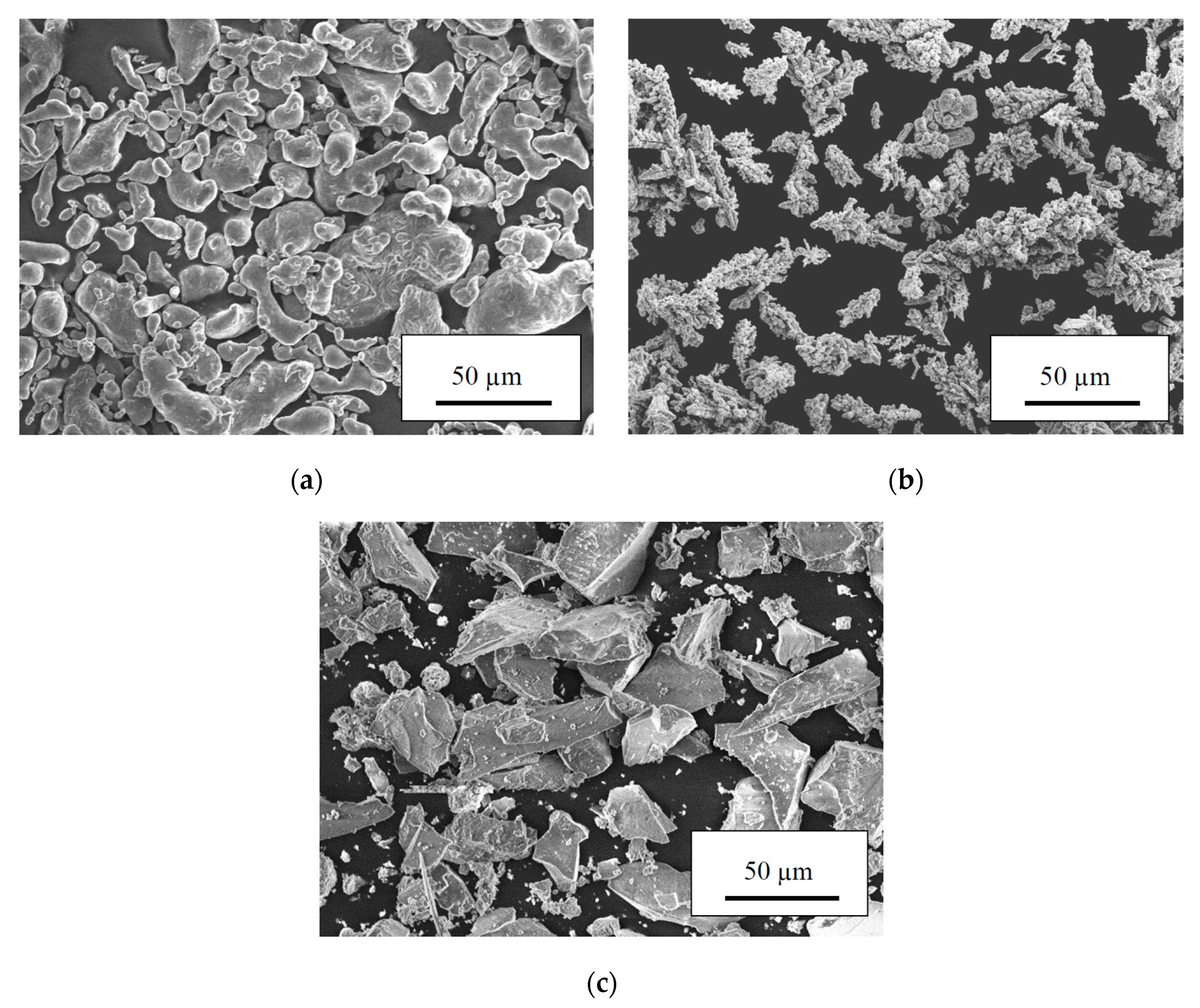
Cold sprayed coatings were deposited onto steel S235JRG2 substrate with dimensions of 1 mm × 25 mm × 45 mm. Three different powders: (1) irregular shape Al with rounded edges, particles size in the range of −41.8+9.4 µm and mean diameter D50 of 17.6 µm (Pyrogarage, Poland), bulk density 1.18 g/cm3, (Figure 1a) (2) dendritic Ni with particles size in the range of −35.3+13.5 µm and mean diameter D50 of 26.3 µm (Pyrogarage, Poland), bulk density 2.4 g/cm3 (Figure 1b) and (3) irregular shape Al2O3 with sharp edges, particles size in the range of −47.7+9.1 µm mean diameter D50 of 29.6 µm (Kos, Poland), bulk density 1.85 g/cm3 (Figure 1c), were mixed to prepare metal-ceramic mixtures with the following proportions of Al + Ni + Al2O3 components: (i) 16 + 42 + 42 wt.%, (ii) 33 + 33 + 34 wt.% and (iii) 49 + 26 + 25 wt.%, respectively. In the following description, to simplify the composition of the mixtures, only the Al content in the mixture is given. Bulk density of prepared powders was measured by weighing 10 cm3 of a ready mixture.
Prior to spraying, the steel samples were degreased and sand-blasted with alumina powder (20 Mesh). A low pressure DYMET 413 device (Obninsk Center for Powder Spraying, Obninsk, Russia) was used to spray the coatings with air as a working gas. The standard circular de Laval nozzle with the throat diameter of 2.5 mm and an outlet diameter of 5 mm was used. The spraying gun was attached to a manipulator (BZT Maschinenbau GmbH, Leopoldshöhe, Germany) moving with a traverse speed of 10 mm/s. The process parameters are presented in Table 1. The powder feed rate was measured by weighing the amount of powder introduced in one minute by a feeder to the spraying gun. The coatings thickness was regulated by number of spraying passes. The as-sprayed low pressure cold sprayed (LPCS) coatings on steel substrate were submitted to the heat treatment processes.
Two types of heat treatment processes were performed: (i) static in a furnace and (ii) dynamic in the resistance spot welding process. In the furnace (Conbest, Poland) samples were submitted to three temperatures: (i) 500 °C, (ii) 560 °C and 620 °C for 4 h to activate long time diffusion in air atmosphere. The parameters of resistance spot welding, for example, welding current, time and electrodes force are collected in Table 2 and were selected to force self-propagating high temperature synthesis. Samples were heated using one or two pulse welding programs (Table 2.) applying 50 Hz AC, 80 kVA spot welding gun and electrodes with a diameter of 10 mm (ASPA, Wroclaw, Poland).
As-sprayed samples after additional post-processing were cut in the middle for the metallographic examination. Their microstructures were analyzed using an SEM (HITACHI S-3400 N, Tokyo, Japan) microscope equipped with SE, BSE detectors and an EDS system for elemental analysis. Moreover, semi-quantitative graphic analysis using ImageJ software was carried out to check porosity and quantity of selected particles in the deposited coatings. Five pictures with magnification of 300 were selected for analysis, and the average percentage value was taken as the result.
X-ray diffraction measurements (Rigaku Ultima IV Diffractometer, Tokio, Japan) were carried out with Cu Kα irradiation (λ = 1.5406 Å) within the range from 15° to 90° in 0.05° steps with an exposure time of 4 s. Prior to analysis, samples with the size of 15 mm × 15 mm were cut off of the material after heat treatment processes as a square around indents left by electrodes.
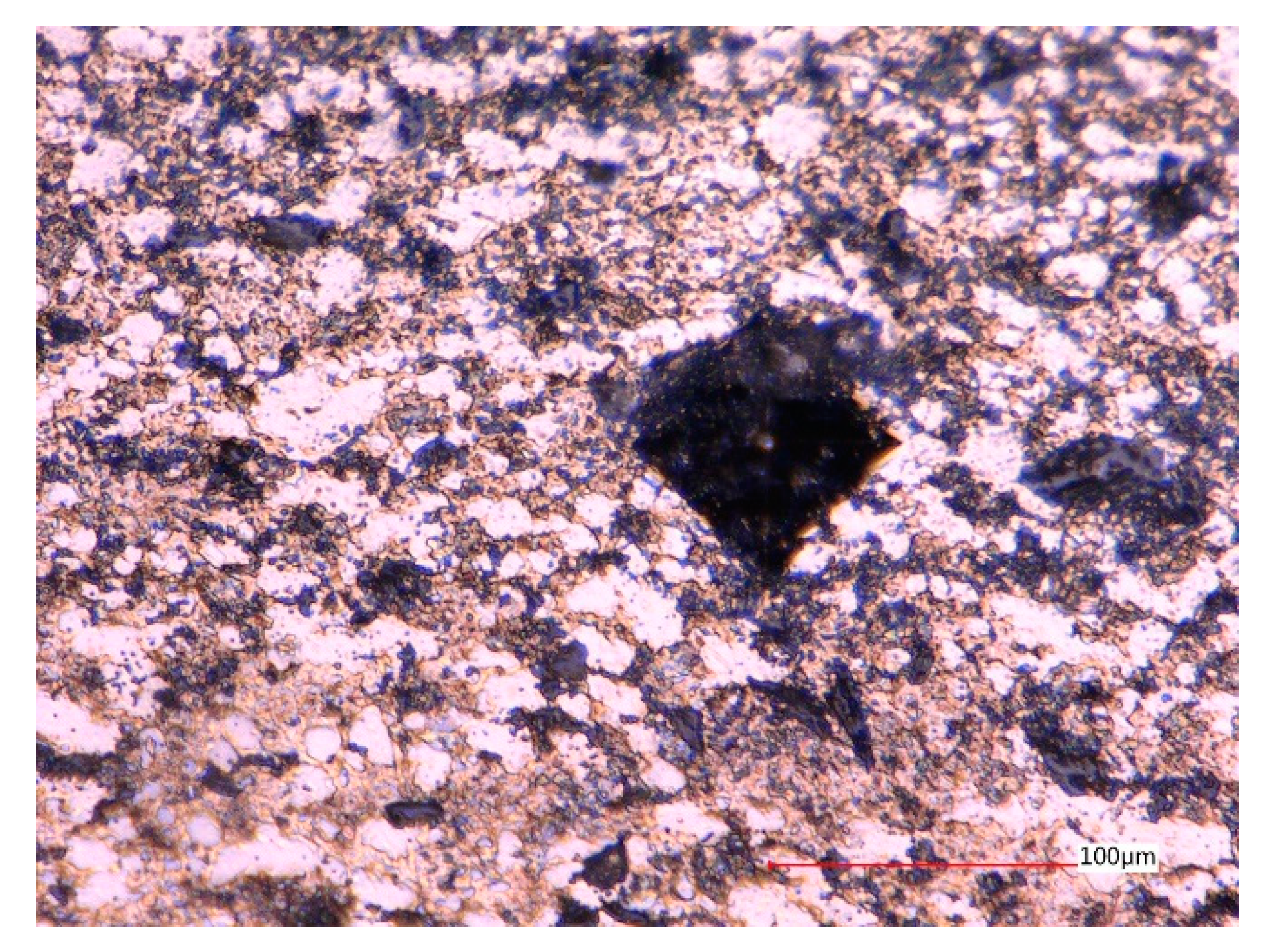
The microhardness was measured by Vickers method using a Digital micro Hardness Tester MMT-X7 MATSUZAWA Co., Ltd. (Akita, Japan) with a sharp pyramidal shaped indenter. A force of 2.94 N was applied with an indent time of 15 s. The high value of a force enabled to measure average hardness of the coating build of various regions, for example, metallic, intermetallic and ceramics. Together, fifteen indents were performed in every coating in the middle of its thickness. Figure 2 shows one of the indentations made in as-sprayed 33% Al coating.
3. Results
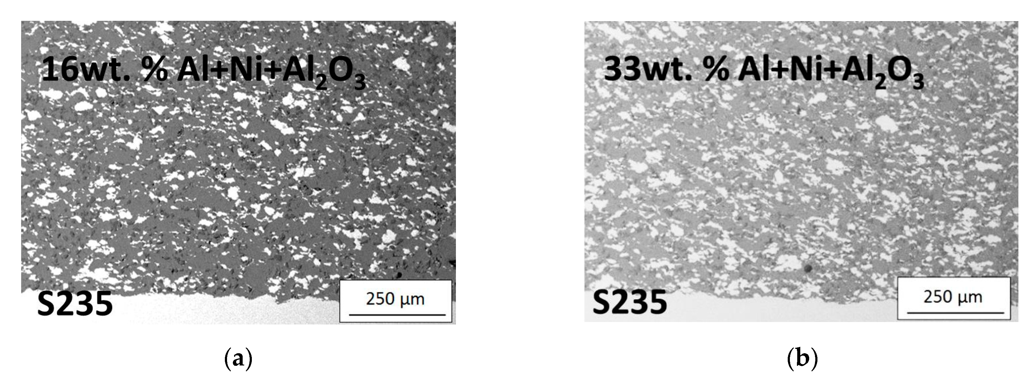
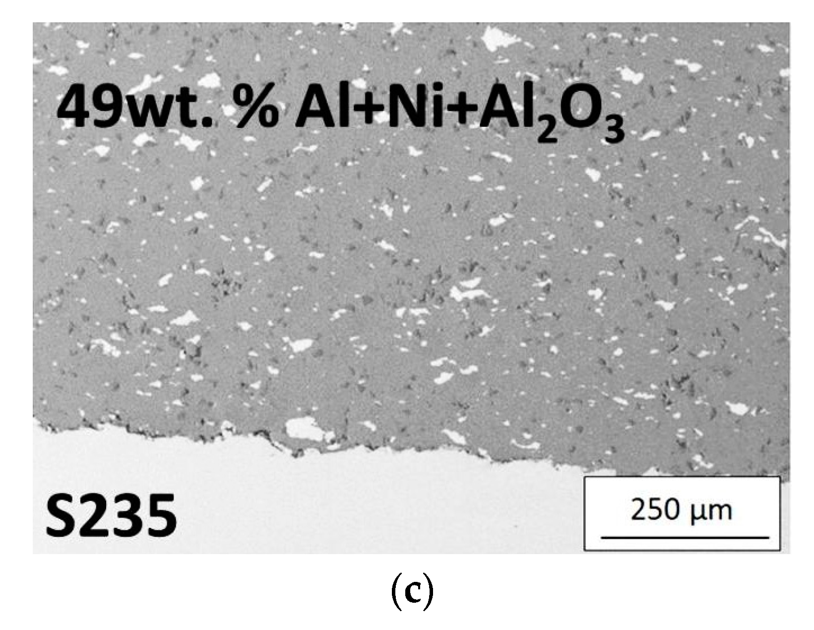
In the performed research, three various mixtures of Al + Ni + Al2O3 were deposited by LPCS onto steel substrate. All examined coatings had considerable density and thickness increasing with the increase of aluminium content in feedstock powder. The smallest thickness of 1.4–1.6 mm was found in coating obtained from feedstock containing 16 wt.% of Al in the mixture. The highest thickness of 1.8–2.1 mm was found in the case of a coating made with powder containing 49 wt.% of aluminium. The microstructures of as-sprayed coatings are shown in Figure 3. A uniform distribution of all components (namely Al-grey, Al2O3-dark grey and Ni-white) in all coatings is clearly visible. The content of the three components in the coatings can be found in Table 3. To simplify the composition of the feedstock powders and final coatings, only the Al content in the initial mixture (in feedstock powder) will be given in the following description. For example, both a powder containing 16% Al in a mixture with Ni and Al2O3 and a coating formed from this mixture will be designated as 16% Al. Analyzing Table 3, it is worth noting that despite large differences in the composition of the initial powders, the composition of two sprayed coatings (16% Al, 33% Al) is similar. Only the composition of the third coating (49% Al) significantly differs from the others. It should be noted that in 49% Al coating, content of Ni and Al2O3 was small and resulted in 5 vol.% and 8 vol.%, respectively. It is noteworthy that the porosity of the obtained coatings increases with a decrease of the content of very plastic metallic aluminium in the initial mixture.
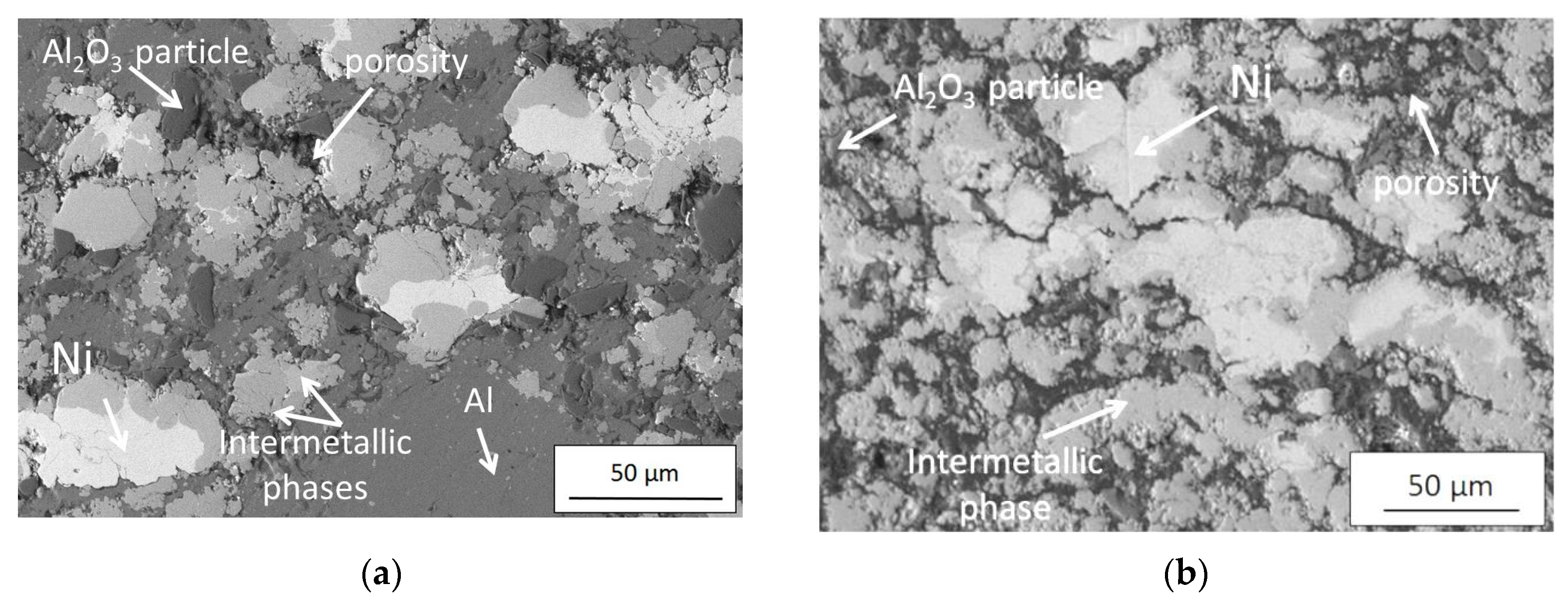
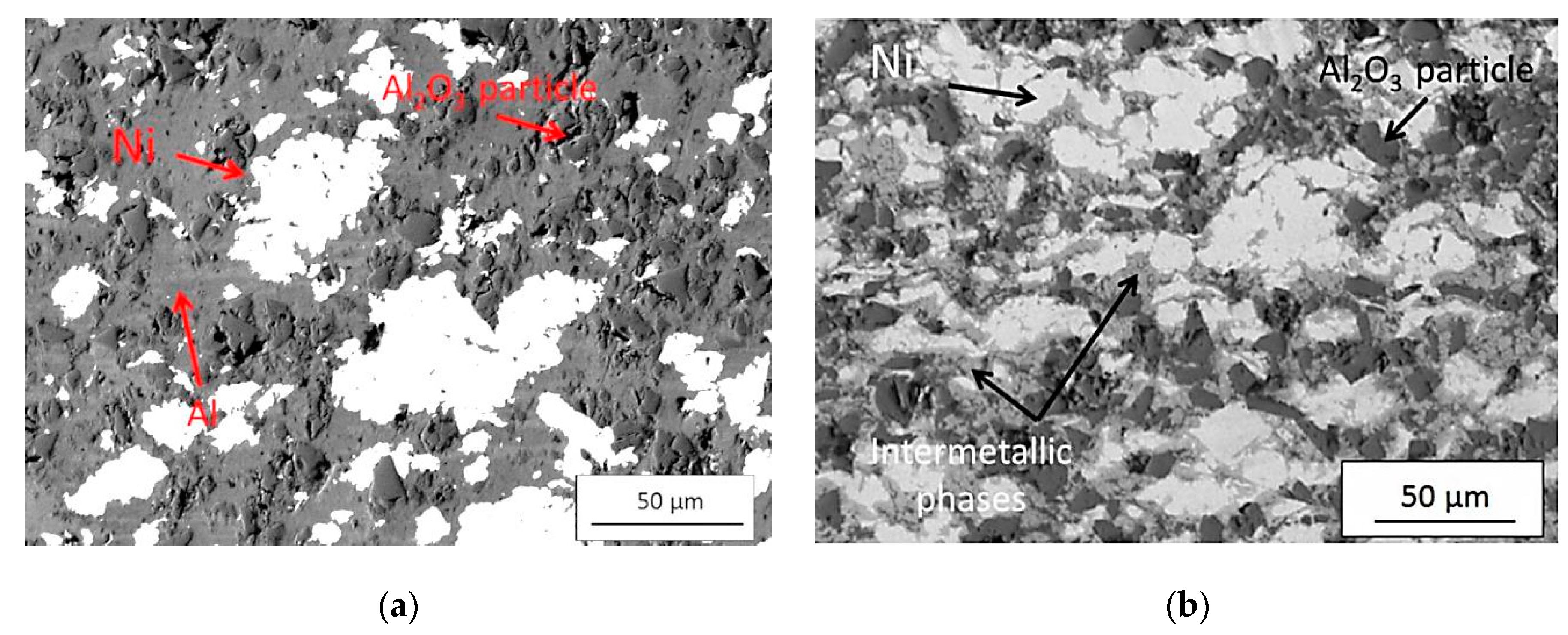
All sprayed coatings were subjected to additional processing in the next stage of the research. It was observed that the furnace heating performed at 500 °C showed negligible changes in the coatings. The microstructure of all coatings subjected to annealing at this temperature was almost the same as it was observed for non-heat treated cold-sprayed coatings. First visible microstructural changes were observed for coatings with heat treated at 560 °C. Figure 4, Figure 5 and Figure 6 show the backscattered (BSE) SEM images of three coatings (16%, 33%, 49% Al) annealed at 560 and 620 °C. The obtained microscopic images clearly show that in addition to the initial phases (Al, Ni, Al2O3), the new phases appear as a result of annealing. The analysis of the microstructure of the coatings heated at 560 and 620 °C also shows that the increase in temperature up to 620 °C intensifies porosity. The porosity estimated on the basis of SEM images varies from 1.5 ± 0.1, 1.1 ± 0.1, 1.0 ± 0.1 (unheated coatings) to 5.0 ± 1.2, 4.6 ± 1.0, 1.7 ± 0.3 (heated at 560 °C) up to 20.8 ± 1.6, 16.3 ± 1.5, 11.7 ± 3.2 (heated at 620 °C) for 16%, 33%, 49% Al coatings.
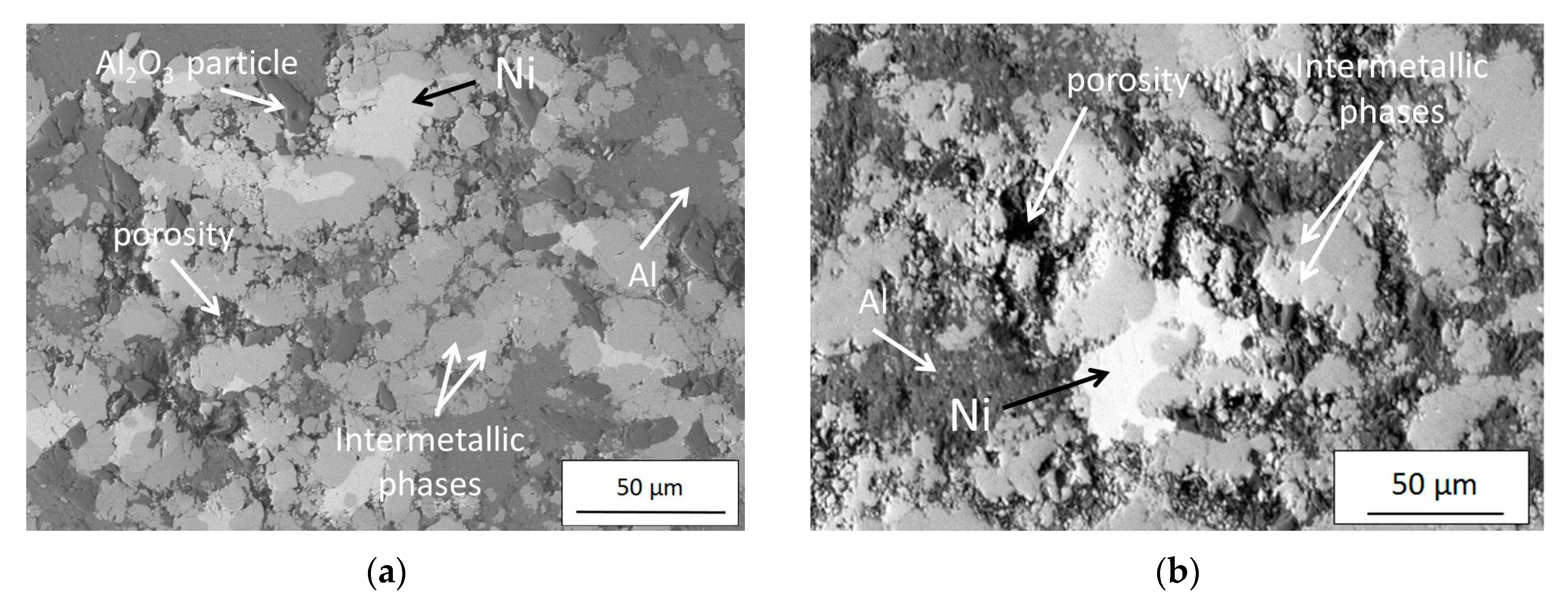
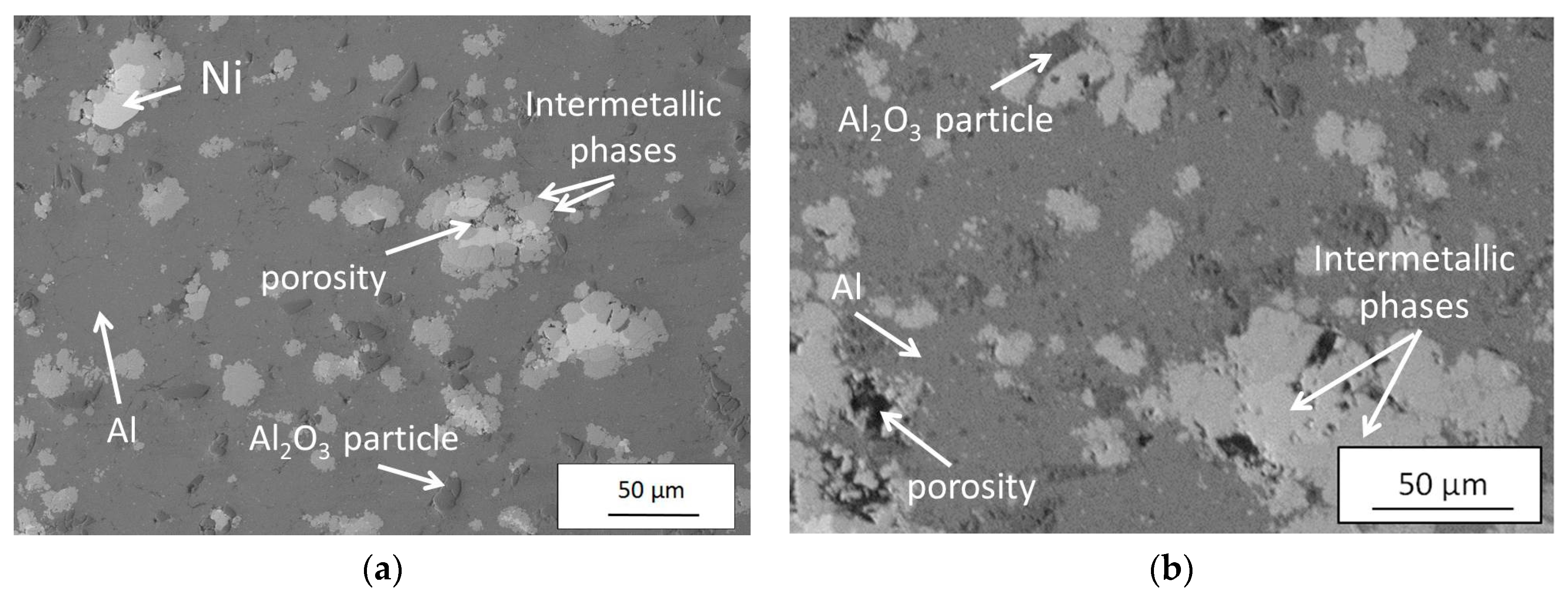
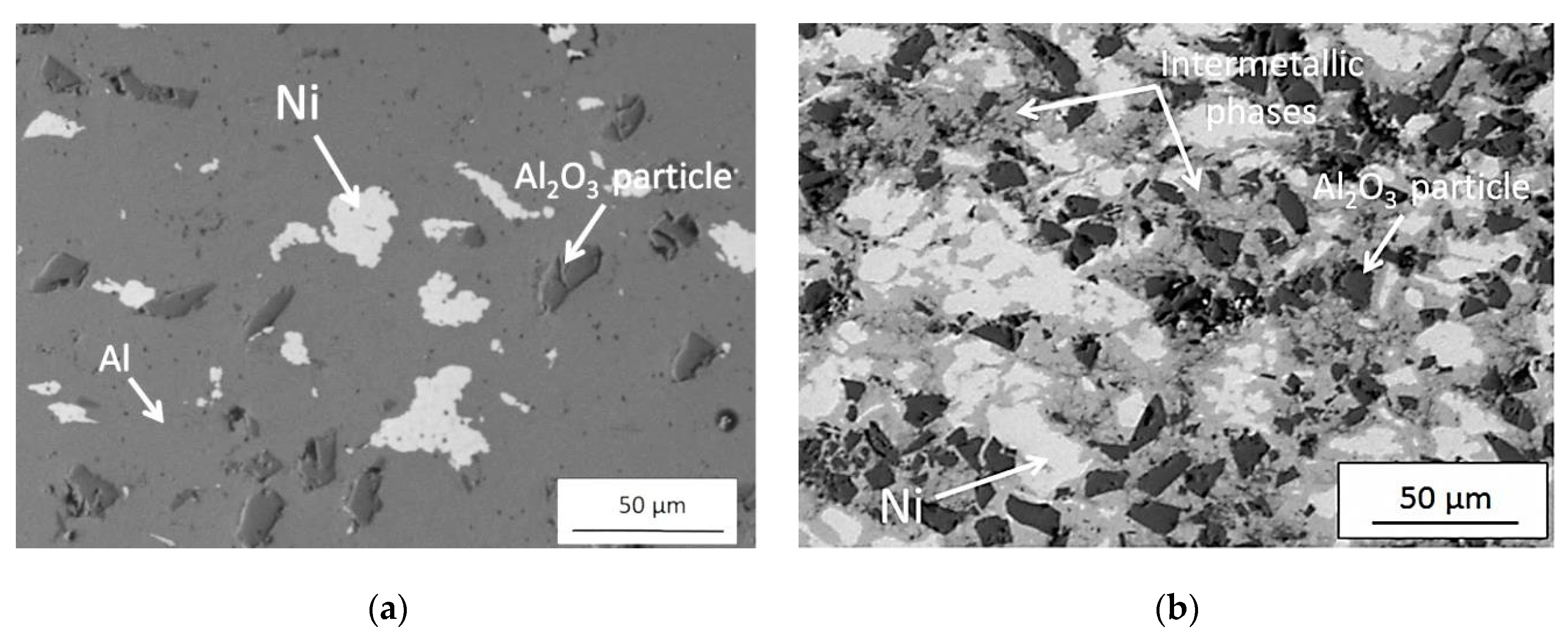
In the next step of the research, how the microstructure of the final coatings will be affected by a process completely different from the conventional furnace heating was tested. Therefore, the coatings were subjected to resistance spot welding. As one might have supposed, samples heat-treated by the resistance spot welding process showed various microstructures depending strongly on process parameters (Table 2). The single-pulse resistance spot welding (parameters No. 1 and 2) revealed no changes in the microstructure of coatings compared to the microstructure before welding. The double-pulse spot welding (parameters No. 3) visibly causes a slight increase in porosity from 1.5 ± 0.1, 1.1 ± 0.1, 1.0 ± 0.1% (in unheated 16% Al, 33% Al, 49% Al coatings) to 3.1 ± 0.6, 2.9 ± 0.5, 1.2 ± 0.2% (Figure 7a, Figure 8a and Figure 9a). However, the analysis of SEM images does not allow us to find any sign of an intermetallic phase in the microstructure of these coatings. In contrast, double-pulse spot welding with parameters No. 4 led to the intensive formation of intermetallic phases (Figure 7b, Figure 8a and Figure 9b) and an increase of porosity to 4.6% ± 2.1%, 4.2% ± 0.7%, 3.7% ± 0.8% in 16% Al, 33% Al and 49% Al coatings, respectively. The resistance spot welding process causing compaction of the coating and as a result all of the coating structures, independently on the powder mixture, was very similar in comparison to furnace heating. Some local porosity was only visible around alumina particles, which were probably crushed while spraying. Intermetallics were formed in the weld region equal to the electrode’s diameter. The reaction was stopped at the boundary of the weld (Figure 10). However, thermal conductivity caused the distribution of intermetallics in the nearest region outside the weld. In the weld region, aluminium diffused and almost completely reacted with nickel, forming intermetallic phases. Moreover, as a result of resistance heating, the temperature was highest in the coating-substrate boundary region and thus the Al-Ni reaction was most intensive next to the substrate.
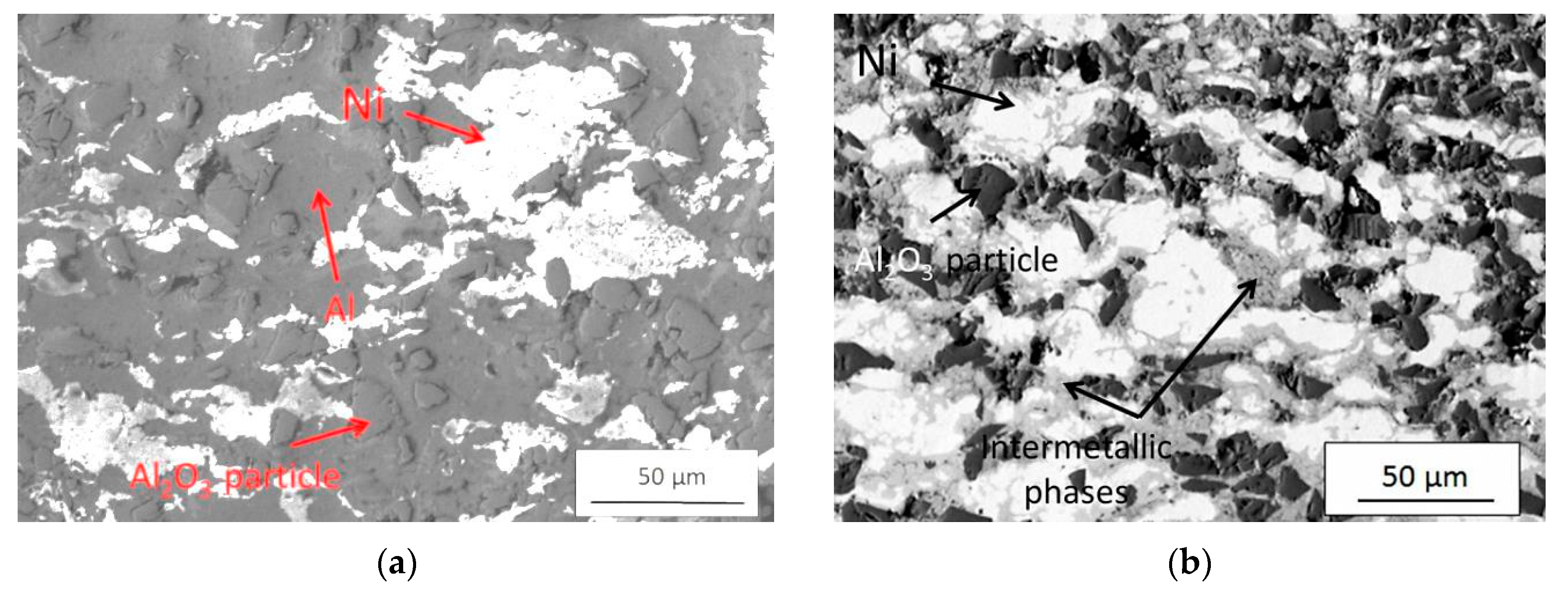
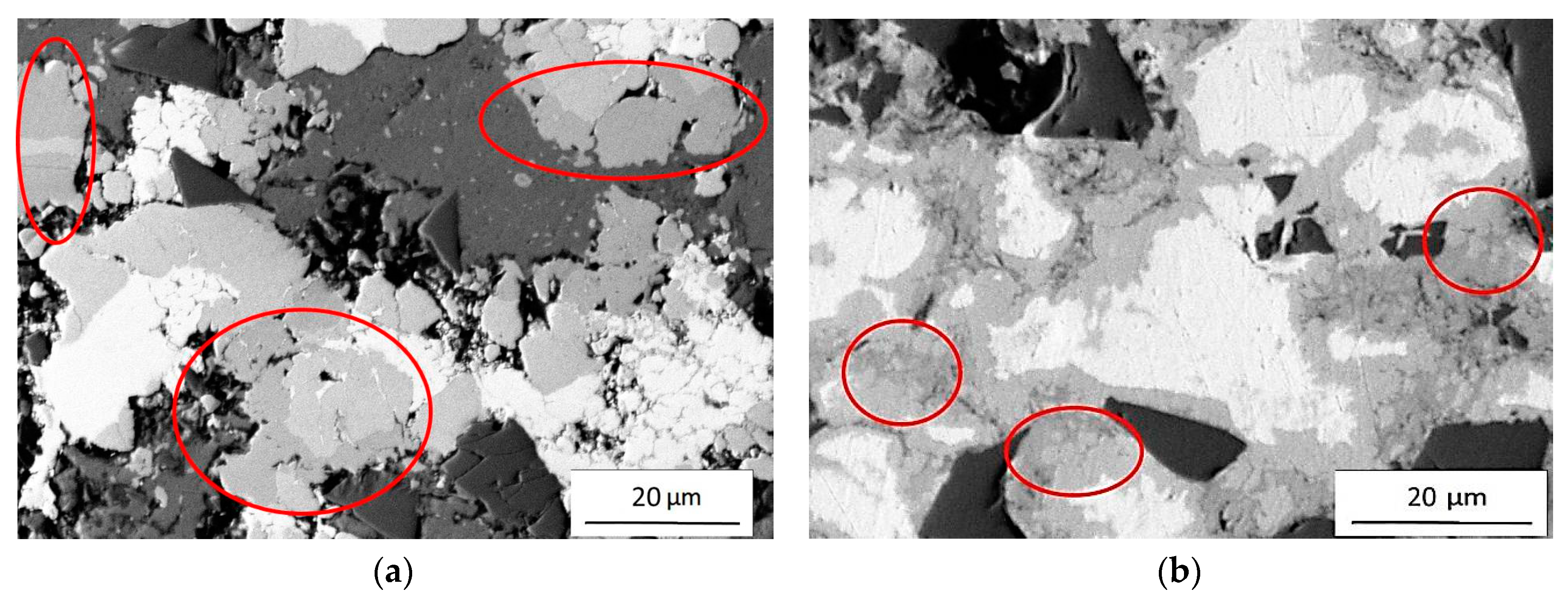
Figure 11 shows a comparison of the microstructure of a 16% Al coating treated by heating at 620 °C in a furnace (Figure 11a) and by resistance spot welding (Figure 11b) (parameters No. 4). This combination of images clearly shows that two various intermetallic phases (identified on backscattered SEM images and marked as the red ellipses) generated while welding are much less visible than on the images of samples heated in a furnace.
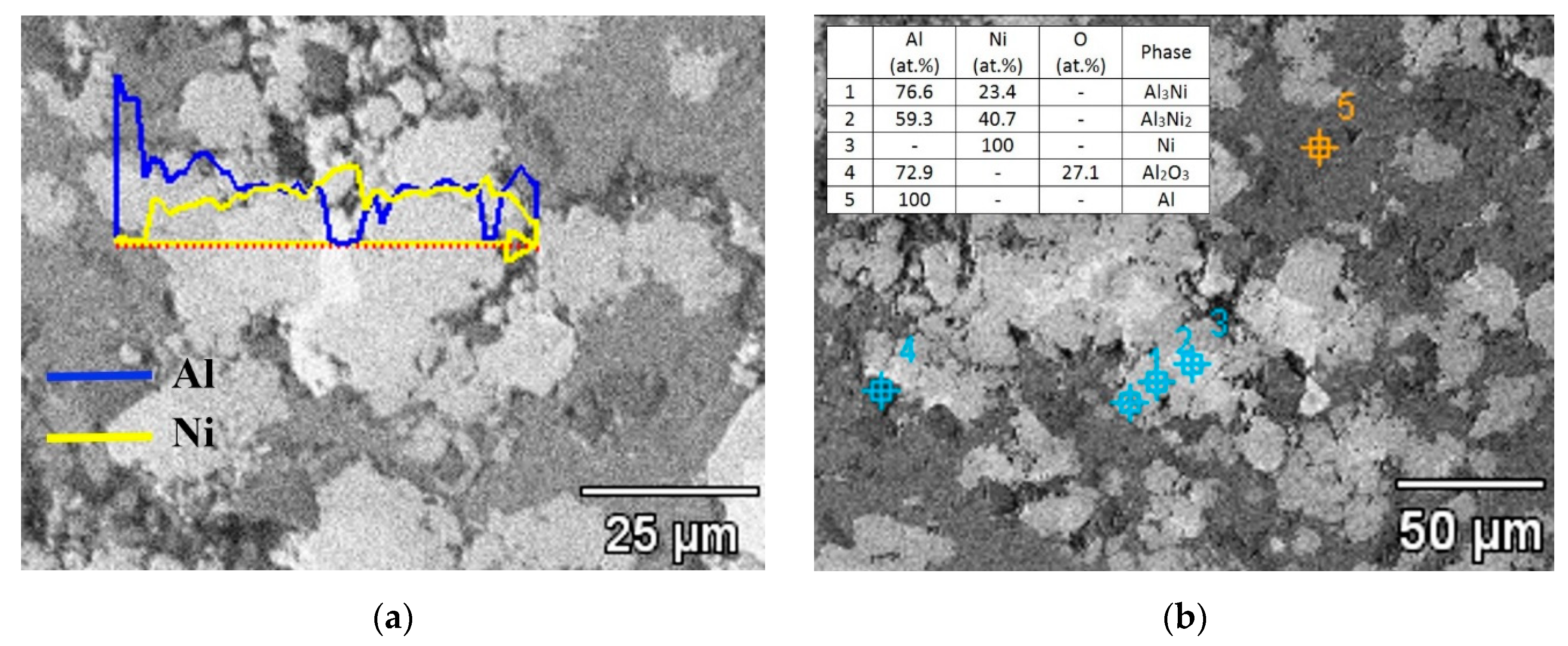
Figure 12 presents microstructure images of the same 16% Al coating after two different post-treatments together with BSE analysis of their chemical elemental composition. Figure 12a presents an SEM image of the coating heated in a furnace at 620 °C. The EDS linear analysis clearly shows the following regions with variable elemental compositions: Al, Al/Ni, Ni/Al, Ni, Ni/Al, Al/Ni and Al where the first mentioned element is dominant in the area (e.g., Al/Ni means that aluminium is dominant in a given area). Figure 12b shows EDS point analysis with precise content (at.%) of individual elements in the coating. Taking into account the atomic values, and XRD analysis presented later in this work, potential intermetallic phases were characterized as: Al3Ni and Al3Ni2.
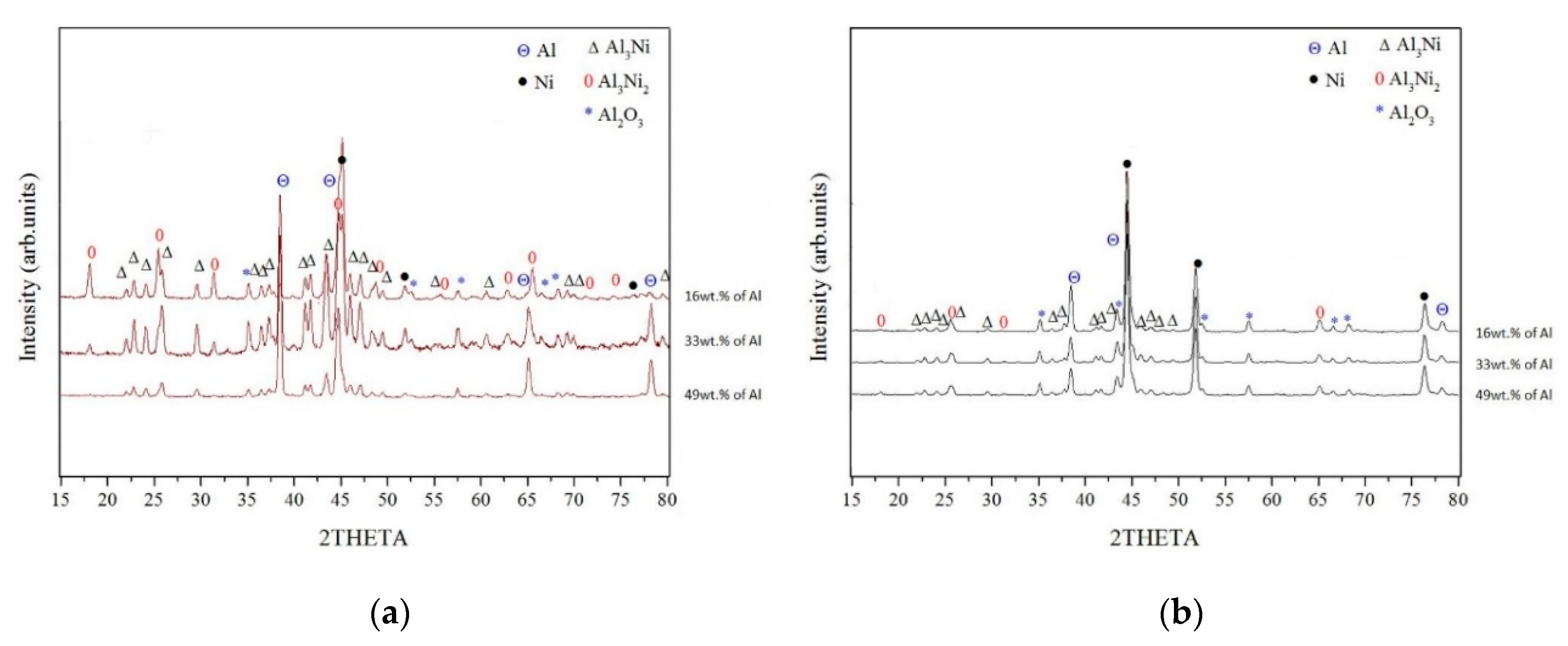
X-ray diffraction measurements were carried out to precisely determine the phase composition of the tested coatings. Figure 13 presents XRD diffraction patterns of all coatings post-treated in a furnace (620 °C) and in the resistance spot welding process (parameters No. 4). Two intermetallic phases Al3Ni and Al3Ni2 were found on diffractograms of all coatings. Comparison of patterns shows that diffraction peaks of intermetallic phases (namely Al3Ni and Al3Ni2) for samples annealed in a furnace are much more significant than for welded samples. It is clearly seen that for samples annealed in a furnace, the type of intermetallic phases and their content depends strongly on the ratio of Ni to Al in the coating before annealing (Figure 13a) whereas for welded samples such dependence is practically invisible (Figure 13b). In the case of the 49% Al coating with the lowest nickel content (5 vol. % of Ni), during the heating in a furnace, mainly Al3Ni phase is formed and diffraction peaks of the Al3Ni2 phase are imperceptible. The rising content of nickel in 33% Al coating (18 vol. % of Ni) evidently leads to the formation of two intermetallic phases: Al3Ni and a small amount of Al3Ni2. Further increase of nickel content (23 vol. % of Ni) in 16% Al coating caused a significant increase in the intensity of Al3Ni2 diffraction peaks while reducing the intensity of Al3Ni peaks. Both intermetallic phases are present in small amounts in relation to the initial phases (Al and Ni) in the welded samples. There are no significant changes in the intensity of diffraction peaks originating from intermetallic phases despite the changing ratio of aluminium to nickel.
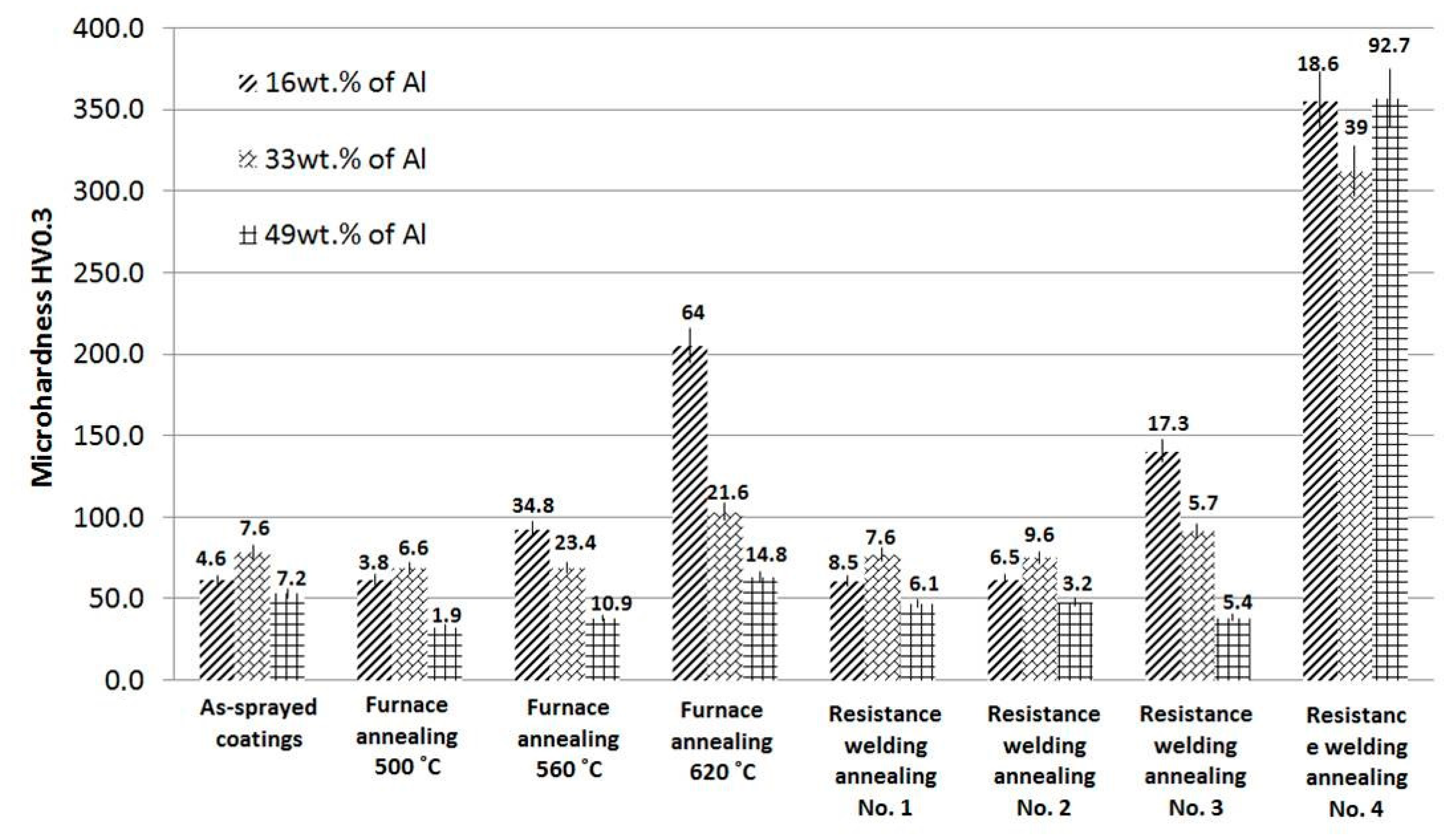
To verify advantages of the heat-treated coatings, the microhardness measurements were performed. Figure 14 compares the results obtained for as-sprayed coatings with results of coatings post-treated with various temperatures and process parameters. The hardness measured for 16% Al, 33% Al and 49% Al coatings before post-treatment processes was 61.3, 77.6 and 53.4 HV0.3, respectively. Regardless of the initial composition, heating in the furnace at 560 and 620 °C did not significantly change the hardness of the coatings. However, heating at 620 °C caused a significant increase in microhardness of all coatings (e.g., 205.4, 103.3 and 63.5 HV0.3 for 16% Al, 33% Al and 49% Al coatings, respectively).
Regardless of the initial composition, single-pulse resistance spot welding process (parameters No. 1 and 2) did not significantly change microhardness of the coatings. First noticeable changes were obtained after double-pulse resistance spot welding with parameters 3. Finally, the use of parameters 4 led to a marked increase in microhardness. The microhardness values determined for coatings after such post-treatment were approximately in the same range and were 358.4 ± 18.6, 309.8 ± 39, 353.2 ± 92.7 HV0.3 for 16% Al, 33% Al and 49% Al coatings, respectively. Relatively high standard deviation values of these measurements confirmed only the local reaction of Al and Ni particles, despite the compact effect of the welding process (Figure 14). Figure 9b clearly shows mixed regions in the coating with clusters of components and local porosity. Despite the high content of aluminium in 49% Al coatings, this component almost entirely diffused and reacted with nickel. Residual aluminium was merely noticed in the boundary regions of the weld (Figure 10). This nonuniformity significantly influenced the measured hardness.
4. Discussion
Analyzing the microstructure of the coatings produced by the method of low-pressure cold spraying with the use of Al, Ni and Al2O3 powders, it can be concluded that all deposited coatings are relatively dense and thick. Relatively low porosity observed in these sprayed coatings can be mainly attributed to the consequence of aluminium and nickel particles densification through the tamping effect of hard ceramics impacting [21,32,33,34]. What is more, the analysis of coating microstructure shows that the content of aluminium in the feedstock affects the thickness of deposited coatings. Therefore, 49% Al coating with the lowest content of nickel and alumina particles shows the highest thickness. High amount of aluminium powder deposited easily when harder nickel and alumina particles provide a tamping effect and afterward bounced off.
As might be expected, heat treatment process performed in a furnace resulted in an increase in the porosity of the coatings. Microstructure analysis of heated samples showed that the lowest process temperature, for example, 500 °C, caused only negligible changes in all coatings microstructure. This is not consistent with the observation of Dean et al., suggesting that material diffusion within the Al-Ni system starts in 450 °C and depends strongly on heating time [20,22,23]. However, this contradiction can be explained by the specificity of coatings deposited by the cold spray method. In such coatings, as it is known, a clear boundary between single particles is observed and what is more, the surface of deposited metals is often covered by a residual oxide layer. So it is obvious that these factors can then significantly slow down the expected diffusion between metal particles.
Microstructure analysis of samples heated in a furnace in temperatures 560 and 620 °C and in resistance spot welding process with parameter No. 3 and 4 showed significant changes resulting from the heating process. Evidently, the application of these more severe post-treatment conditions resulted in intensive diffusion of the metallic components and consequently in the formation of intermetallic phases.
The final quantity of intermetallic phases depended strongly on the prepared powder mixture. However, both heating processes provide different results. In the case of furnace heating, the SEM, XRD and microhardness measurement analyses showed that the higher nickel particles content in the reaction mixture caused more intensive intermetallic phase formation while in the case of resistance spot welding process this effect is unnoticeable. This effect can be attributed to the compacting of particles due to the simultaneous action of the pressure exerted by the electrodes and the heat generated in this process. As a result, aluminium and nickel undergo plastic deformation, thus increasing the contact surface of both phases and intensifying the reaction, and thus microhardness.
According to the literature, there are two possible mechanisms responsible for intermetallic phases formation during the thermal treatment: (i) a long time diffusion of metal atoms initiating reaction when a sample stays a specified time in a furnace at elevated temperature or (ii) a self-propagating high temperature synthesis (SHS) when synthesis is initiated by a heating point and exothermic reaction sweeps through the material [20,35]. The furnace heating initiates diffusion but the intensity of transformation depends on process temperature. Microscopic analyses of furnace-heated samples showed that the strong disadvantage of this process was the increased porosity of the final coatings compared to as-sprayed coatings. In the case of the resistance spot welding process, high temperature combined with high pressure exerted by electrodes minimalized coatings porosity. It should be remembered that the time of the resistance spot welding process was incredibly short—800 ms. The process was even faster than initiated by laser in Al-Ni cold sprayed coating SHS reaction described in [20]. It is obvious that SHS reaction begins with the melting of the component with the lower melting point, in the case of the Al-Ni binary system it is aluminium. The next stage is the diffusion of aluminium and the formation of intermetallic phases. First, the phases are rich in Al. In the case of the coatings tested in this work, the intermetallic phase that was observed is Al3Ni. It can be clearly seen in SEM images (Figure 10) that Al3Ni forms a thin film at the Ni/Al interface. The second intermetallic phase observed in SEM images, identified in the XRD studies as Al3Ni2, is formed after exceeding the melting point of Al3Ni at 854 ˚C [20] and its content increases with the increase of temperature and the proportion of Ni in the reaction mixture.
Mechanical properties analyzed on the basis of the microhardness measurements showed considerable differences. Microhardness of 49% Al coating heated in a furnace at 500 and 560 °C slightly decreased in comparison to as-sprayed coatings. It arises from the annealing and softening process of aluminium and nickel that occurred in the coating. However, in the case of resistance spot welding, even milder welding parameters (No. 1 and No. 2) lead to increased coating hardness. This can be explained by strong work hardening of material provided by that resistance spot welding process.
A comparison of all analyzed samples heated in a furnace at 620 °C showed that among all, the highest microhardness (of 205.4 HV0.3) has the 16% Al coating. However, the same sample (16% Al) subjected to resistance welding (parameters No. 4) shows an even higher microhardness (358.4 HV0.3). This increased hardness can be attributed to the SHS reaction initiated in the resistance spot welding process together with additional pressure minimalizing porosity and thus significantly affecting coating hardness.
The microhardness and final coating porosity of cold sprayed coatings depend not only on spraying parameters but also on morphology, oxidation and deformation level of feedstock powder material [36]. Additional post-treatment process provides further microstructure modification, for example, structure recovery, recrystallization, grain growth, phase transformation. This modification can provide in the same coating locally both an increase and decrease of microhardness [31]. Therefore 49% Al coating heated in a furnace at 620 °C showed microhardness comparable to as-sprayed coating. Despite that the hard intermetallic phases formed only locally, what was confirmed by XRD, aluminium matrix was annealed, recovered and thus softened. With increasing content of Al3Ni and Al3Ni2 phases in 16% Al and 33% Al coatings heated in a furnace, the microhardness increased. It arises from high hardness of intermetallics. Ke et al. measured microhardness of Al3Ni2 and Al3Ni intermetallics as 1283 HV0.05 and 841 HV0.05 respectively in the sample heat treated by 550 °C for 6 h [37]. Therefore, despite the comparable amount of nickel and porosity in deposited 16% Al and 33% Al coatings (23% and 18 vol. % of Ni; 20.8% and 16.3% of porosity, respectively) the highest hardness of 205.4 HV0.3 showed 16% Al coating after furnace heating at 620 °C. On the other hand, samples heated in the resistance spot welding process, independently on powder mixture, showed a similar amount of both intermetallic phases. The additional pressure exerted by the electrodes pressing the coating material causes the thickening of intermetallic phases in the area of the weld. As a result, microhardness of all three coatings was also comparable. Nevertheless, standard errors showed increasing divergence in the coating microhardness resulting from residual nickel in the coating, locally present reaction regions and mixed regions with porosity and cluster of components. Despite the densification, the coating with the highest aluminium content showed the largest spread of measured values. In comparison to furnace diffusion, the resistance spot welding process initiated an SHS reaction that together with additional pressure minimalized porosity and significantly increased coatings hardness. It should be noted that resistance spot welding provides heating of a small area. Therefore, further research is needed using resistance linear welding or using appropriate modifications in resistance spot welding that finally will enable large area structure modifications.
5. Conclusions
In the presented paper, aluminium, nickel and alumina powders were mixed with various proportions and deposited by a low pressure cold spraying unit. As a result of alumina, the obtained coatings were dense and successfully further used in post-treatment heating. Two different heating processes were applied: (i) the furnace and (ii) the resistance spot welding process. Furnace heating was a static process while the resistance spot welding process was dynamic, both with and without control of temperature, respectively.
The heating process performed in a furnace showed meaningful changes in microstructure. The process started a long time diffusion and as a result, porosity increased rapidly, especially in 16% Al coating. The intensity of diffusion depended strongly on nickel addition and heating temperature as well. The more nickel powder in the coating, the faster diffusion proceeded. However, below 560 °C there were negligible changes to the microstructure of the coatings. The resistance spot welding process made progress in decreasing porosity. The additional pressure of 4 kN during heating significantly decreased porosity. The heating processes led to the formation of intermetallic phases. EDS and XRD analysis confirmed the presence of Al3Ni and Al3Ni2 phases. The pressure exerted by electrodes with additional heating compacted particles and thus aluminium and nickel increased the area of particles surface boundary and intensified the reaction.
Coating modifications provide interesting changes in the coating microhardness. Furnace heating with 500 °C of coatings with the highest aluminium content (49% Al) caused an annealing effect and microhardness decreased. On the other hand, intensive diffusion despite increased porosity provides the formation of intermetallic phases. As a result, coatings hardness increased up to 205.4 HV0.3. Additional pressure in the resistance spot welding process provided by electrodes compacted the coating material and intermetallics densification occurred. As a result, the microhardness of all three coatings was also comparable with the highest result of 358.4 HV0.3.
Author Contributions
Conceptualization, M.W. and M.K.; methodology, M.W, M.J., A.B. and M.K.; software, M.W.; validation, M.W., M.J., A.B. and M.K.; formal analysis, M.W. and A.B.; investigation, M.W., M.J., A.B. and M.K.; resources, M.W. and M.J.; data curation, M.W.; writing, original draft preparation, M.W. and A.B.; writing, review and editing, M.W., M.J., A.B. and M.K.; visualization, M.W.; supervision, M.W.; project administration, M.W.; funding acquisition, M.W. All authors have read and agreed to the published version of the manuscript.
Funding
This research was funded by the Polish National Science Center under grant no. 2016/23/D/ST8/00675 (Project title: The mechanism of joining submicron ceramic particles in the cold spraying process).
Conflicts of Interest
The authors declare no conflict of interest. The funders had no role in the design of the study; in the collection, analyses, or interpretation of data; in the writing of the manuscript, or in the decision to publish the results.
References
- Jozwik, P.; Polkowski, W.; Bojar, Z. Applications of Ni3Al Based Intermetallic Alloys—Current Stage and Potential Perceptivities. Materials 2015, 8, 2537–2568. [Google Scholar] [CrossRef]
- Kumar, K.G.; Sivarao, T.; Anand, J.S. A Novel Intermetallic Nickel Aluminide (Ni3Al) as an Alternative Automotive Body Material. Int. J. Eng. Technol. 2011, 11, 208–215. [Google Scholar]
- Korotkov, V.A. Wear resistance of carbon steel with different types of hardening. J. Frict. Wear 2015, 36, 149–152. [Google Scholar] [CrossRef]
- Yu, Y.; Zhou, J.; Chen, J.; Zhou, H.; Guo, C.; Guo, B. Preparation, microstructure and tribological properties of Ni3Al intermetallic compound coating by laser cladding. Intermetallics 2010, 18, 871–876. [Google Scholar] [CrossRef]
- Mitra, R. Intermetallic matrix composites: Properties and application, 1st ed.; Woodhead Publishing: Cambridge, United Kingdom, 2018; pp. 37–59. [Google Scholar]
- Schulson, E.M. Brittle fracture and toughening. In Physical Metallurgy and Processing of Intermetallic Compounds, 1st ed.; Stoloff, N.S., Sikka, V.K., Eds.; Chapman & Hall: London, UK, 1996; pp. 56–94. [Google Scholar]
- Yamaguchi, M.; Shirai, Y. Defect structures. In Physical Metallurgy and Processing of Intermetallic Compounds, 1st ed.; Stoloff, N.S., Sikka, V.K., Eds.; Chapman & Hall: London, UK, 1996; pp. 3–27. [Google Scholar]
- Senderowski, C.; Zasada, D.; Durejko, T.; Bojar, Z. Characterization of as-synthesized and mechanically milled Fe–Al powders produced by the self-disintegration method. Powder Technol. 2014, 263, 96–103. [Google Scholar] [CrossRef]
- Senderowski, C. Nanocomposite Fe–Al intermetallic coating obtained by gas detonation spraying of milled self-decomposing powder. J. Therm. Spray Technol. 2014, 23, 1124–1134. [Google Scholar] [CrossRef] [Green Version]
- Wu, X. Review of alloy and process development of TiAl alloys. Intermetallics 2006, 14, 1114–1122. [Google Scholar] [CrossRef]
- Sikka, V.K.; Deevi, S.C.; Viswanathan, S.R.; Swindeman, W.; Santella, M.L. Advances in processing of Ni3Al-based intermetallics and applications. Intermetallics 2000, 8, 1329–1337. [Google Scholar] [CrossRef]
- Yamaguchi, M.; Inui, H.; Ito, K. High-temperature structural intermetallics. Acta Mater. 2000, 48, 307–322. [Google Scholar] [CrossRef]
- Cinca, N.; Carlos Roberto Camello Lima, C.R.C.; Guilemany, J.M. An overview of intermetallics research and application: Status of thermal spray coatings. J. Mater. Res. Technol. 2013, 2, 75–86. [Google Scholar] [CrossRef] [Green Version]
- Bochenek, K.; Basista, M. Advances in processing of NiAl intermetallic alloys and composites forhigh temperature aerospace applications. Prog. Aerosp. Sci. 2015, 79, 136–146. [Google Scholar] [CrossRef]
- Frommeyer, G.; Rablbauer, R. High temperature materials based on the intermetallic compound niai reinforced by refractory metals for advanced energy conversion technologies. Mater. Technol. 2008, 79, 507–512. [Google Scholar]
- Bała, P. New tool materials based on Ni alloys strengthened by intermetallic compounds with a high carbon content. Arch. Mater. Sci. Eng. 2010, 42, 5–12. [Google Scholar]
- Evdokimenko, Y.I.; Kisel, V.M.; Buchakov, S.V.; Rogozinskaya, A.A.; Yurchenko, D.Z.; Litvin, R.V. Properties of intermetallic Ni–Al coatings deposited by high-velocity air–fuel spraying. Powder Metall. Met. Ceram. 2010, 49, 660–666. [Google Scholar] [CrossRef]
- Deshpande, S.; Sampath, S.; Gouma, P.; Herman, H. Microstructural characterization across length scales of thermal sprayed Ni-5wt% Al coatings. In Proceedings of the Thermal Spray 2003: Advancing the science and applying the technology, Orlando, FL, USA, 5–8 May 2003; Marple, B.R., Moreau, C., Eds.; ASM International: Cleveland, OH, USA, 2003; pp. 1419–1428. [Google Scholar]
- Dean, S.W.; Potter, J.K.; Yetter, R.A.; Eden, T.J.; Champagne, V.; Trexler, M. Energetic intermetallic materials formed by cold spray. Intermetallics 2013, 43, 121–130. [Google Scholar] [CrossRef]
- Maev, R.; Leshchynsky, V. Air Gas Dynamic Spraying of Powder Mixtures: Theory and Application. J. Therm. Spray Technol. 2006, 15, 198–205. [Google Scholar] [CrossRef]
- Lee, H.; Lee, S.; Ko, K. Annealing effects on the intermetallic compound formation of cold sprayed Ni, Al coatings. J. Mater. Process. Technol. 2009, 209, 937–943. [Google Scholar] [CrossRef]
- Lee, H.Y.; Jung, S.H.; Lee, S.Y.; Ko, K.H. Fabrication of cold sprayed Al-intermetallic compounds coatings by post annealing. Mater. Sci. Eng. A 2006, 433, 139–143. [Google Scholar] [CrossRef]
- Bakan, E.; Mauer, G.; Sohn, Y.J.; Schwedt, A.; Rackel, M.W.; Riedlberger, F.; Pyczak, F.; Peters, J.O.; Mecklenburg, M.; Gartner, T.M.; et al. Cold gas spraying of Ti-48Al-2Cr-2Nb intermetallic for jet engine applications. Surf. Coat. Technol. 2019, 371, 203–210. [Google Scholar] [CrossRef]
- Ko, K.H.; Lee, H.; Choi, J.O. Effect of Sn particle size on the intermetallic compound formations of cold sprayed Sn–Ni coatings. Appl. Surf. Sci. 2011, 257, 2970–2977. [Google Scholar] [CrossRef]
- Huang, C.; Li, W.; Planche, M.-P.; Liao, H.; Montavon, G. In-situ formation of Ni-Al intermetallics-coated graphite/Al composite in a cold-sprayed coating and its high temperature tribological behaviors. J. Mater. Sci. Technol. 2017, 33, 507–515. [Google Scholar] [CrossRef]
- Sichani, H.R.; Salehi, M.; Edris, H.; Farani, M.T. The effect of APS parameter on the microstructural, mechanical and corrosion properties of plasma sprayed Ni-Ti-Al intermetallic coatings. Surf. Coat. Technol. 2017, 309, 959–968. [Google Scholar] [CrossRef]
- Gitae Park, G.; Uhm, S.; Lee, C. Effects of in-situ post-weld heat treatment on the microstructure and mechanical properties of the coarse-grained heat-affected zone in a resistance spot weld in medium Mn TRIP steel. Mater. Sci. Eng. A 2020, 788, 139477. [Google Scholar] [CrossRef]
- Sajjadi-Nikoo, S.; Pouranvari, M.; Abedi, A.; Ghaderi, A.A. In situ postweld heat treatment of transformation induced plasticity steel resistance spot welds. Sci. Technol. Weld. Join. 2018, 23, 71–78. [Google Scholar] [CrossRef]
- Hwang, I.; Cho, H.; Nam, S.; Kang, M.; Koo, M.-S.; Kim, Y.-M. Effects of post-weld heat treatment on mechanical properties and microstructure of resistance spot – welded lightweight steel. Int. J. Adv. Manuf. Technol. 2019, 104, 4813–4825. [Google Scholar] [CrossRef]
- Wei, S.T.; Lv, D.; Liu, R.D.; Lin, L.; Xu, R.J.; Guo, J.Y.; Wang, K.Q. Similar and dissimilar resistance spot welding of advanced high strength steels: Welding and heat treatment procedures, structure and mechanical properties. Sci. Technol. Weld. Join. 2014, 19, 427–435. [Google Scholar] [CrossRef]
- Champagne, V. The Cold Spray Materials Deposition Process: Fundamentals and Applications, 1st ed.; Woodhead Publishing Ltd.: Cambridge, United Kingdom, 2007; pp. 302–314. [Google Scholar]
- Jenkins, R.; Yin, S.; Aldwell, B.; Meyer, M.; Lupoi, R. New insights into the in-process densification mechanism of cold spray Al coatings: Low deposition efficiency induced densification. J. Mater. Sci. Technol. 2019, 35, 427–431. [Google Scholar] [CrossRef]
- Sabard, A.; McNutt, P.; Begg, H.; Hussain, T. Cold spray deposition of solution heat treated, artificially aged and naturally aged Al 7075 powder. Surf. Coat. Technol 2020, 385, 125367. [Google Scholar] [CrossRef]
- Qiu, X.; Tariq, N.-H.; Qi, L.; Tang, J.-R.; Cui, X.-Y.; Du, H.; Wang, J.-Q.; Xiong, T.-Y. Influence of particulate morphology on microstructure and tribological properties of cold sprayed A380/Al2O3 composite coatings. J. Mater. Sci. Technol. 2020, 44, 9–18. [Google Scholar] [CrossRef]
- Morsi, K. Review: Reaction synthesis processing of Ni–Al intermetallic materials. Mater. Sci. Eng. A 2001, 299, 1–15. [Google Scholar] [CrossRef]
- Koivuluoto, H.; Vuoristo, P. Effect of Powder Type and Composition on Structure and Mechanical Properties of Cu + Al2O3 Coatings Prepared by using Low-Pressure Cold Spray Process. J. Therm. Spray Technol. 2010, 19, 1081–1092. [Google Scholar] [CrossRef]
- Ke, L.; Huang, C.; Xing, L.; Huang, K. Al–Ni intermetallic composites produced in situ by friction stir processing. J. Alloys Compd. 2010, 503, 494–499. [Google Scholar] [CrossRef]
Figure 1.
SEM images of powders used in the research: spheroidal aluminium (a), dendritic nickel (b) and irregular alumina (c).
Figure 1.
SEM images of powders used in the research: spheroidal aluminium (a), dendritic nickel (b) and irregular alumina (c).

Figure 2.
Light microscope image of indentation in as-sprayed 33% Al coating.

Figure 3.
As-sprayed coatings (SEM, BSE) of Al+Ni+Al2O3 with 16 wt.% of Al (a), 33 wt.% of Al (b), 49 wt.% of Al (c).
Figure 3.
As-sprayed coatings (SEM, BSE) of Al+Ni+Al2O3 with 16 wt.% of Al (a), 33 wt.% of Al (b), 49 wt.% of Al (c).


Figure 4.
Micrographs (SEM, BSE) of 16% Al coating heated in furnace at 560 °C (a) and 620 °C (b).

Figure 5.
Micrographs (SEM, BSE) of 33% Al coating heated in furnace at 560 °C (a) and 620 °C (b).

Figure 6.
Micrographs (SEM, BSE) of 49% Al coating heated in furnace at 560 °C (a) and 620 °C (b).

Figure 7.
Micrographs (SEM, BSE) of 16% Al coating heated by resistance spot welding process with parameters No. 3 (a) and No. 4 (b).
Figure 7.
Micrographs (SEM, BSE) of 16% Al coating heated by resistance spot welding process with parameters No. 3 (a) and No. 4 (b).

Figure 8.
Micrographs (SEM, BSE) of 33% Al coating heated by resistance spot welding process with parameters No. 3 (a) and No. 4 (b).
Figure 8.
Micrographs (SEM, BSE) of 33% Al coating heated by resistance spot welding process with parameters No. 3 (a) and No. 4 (b).

Figure 9.
Micrographs (SEM, BSE) of 49% Al coating heated by resistance spot welding process with parameters No. 3 (a) and No. 4 (b).
Figure 9.
Micrographs (SEM, BSE) of 49% Al coating heated by resistance spot welding process with parameters No. 3 (a) and No. 4 (b).

Figure 10.
Intermetallics formation in the center (a) and at the boundary (b) of weld in 49% Al coating heated by resistance spot welding process with parameters No. 4.
Figure 10.
Intermetallics formation in the center (a) and at the boundary (b) of weld in 49% Al coating heated by resistance spot welding process with parameters No. 4.

Figure 11.
Micrographs (SEM, BSE) of 16% Al coating heated in furnace-620 °C (a) and by resistance spot welding process-parameters No. 4 (b). Red ellipses highlight two various intermetallic phases.
Figure 11.
Micrographs (SEM, BSE) of 16% Al coating heated in furnace-620 °C (a) and by resistance spot welding process-parameters No. 4 (b). Red ellipses highlight two various intermetallic phases.

Figure 12.
EDS analysis of 16% Al coating: heated in a furnace at 620 °C (a) and heated by resistance spot welding process with parameters 4 (b).
Figure 12.
EDS analysis of 16% Al coating: heated in a furnace at 620 °C (a) and heated by resistance spot welding process with parameters 4 (b).

Figure 13.
XRD diffraction patterns of coatings heat-treated in furnace-620 °C (a) by resistance spot welding process-parameters No. 4 and (b).
Figure 13.
XRD diffraction patterns of coatings heat-treated in furnace-620 °C (a) by resistance spot welding process-parameters No. 4 and (b).

Figure 14.
Microhardness of as-sprayed and heat-treated coatings with standard deviation values above posts.
Figure 14.
Microhardness of as-sprayed and heat-treated coatings with standard deviation values above posts.


Table 1.
Low pressure cold sprayed (LPCS) parameters.
| As-Sprayed Coating Designation | Al + Ni + Al2O3 Powder Mixture, wt.% | Powder Feed Rate, g/min | Traverse Speed, mm/s | Gas Preheating Temperature, °C | Gas Pressure, MPa | Stand-Off, mm | Number of Spray Passes |
|---|---|---|---|---|---|---|---|
| 16% Al | 16 + 42 + 42 | 17 | 10 | 500 | 0.9 | 10 | 2 |
| 33% Al | 33 + 34 + 33 | 14 | 2 | ||||
| 49% Al | 49 + 26 + 25 | 9 | 3 |
Table 2.
Resistance spot welding process parameters.
| No. | Pulse 1 | Pulse 2 | ||||
|---|---|---|---|---|---|---|
| Welding Current (kA) | Welding Time (ms) | Welding Force (kN) | Welding Current (kA) | Welding Time (ms) | Welding Force (kN) | |
| 1 | 5.1 | 1000 | 4 | - | - | - |
| 2 | 9.3 | 1000 | 4 | - | - | - |
| 3 | 8 | 200 | 3.5 | 16 | 280 | 3.5 |
| 4 | 8 | 200 | 3.5 | 16 | 600 | 3.5 |
Table 3.
Composition of feedstock powders and corresponding coatings.
| Designation | Feedstock Powder | Coatings | |||
|---|---|---|---|---|---|
| Mass Percent of Ingredients in the Feedstock (wt.%) | Volume Percent of Ingredients in the Feedstock (vol.%) | Bulk Density (g/cm3) | Volume Percent of Ingredients in the Coating (vol.%) Al-Ni-Al2O3 | Porosity (%) | |
| 16% Al | 16-42-42 | 25-33-42 | 1.95 | 63-23-14 | 1.5 ± 0.1 |
| 33% Al | 33-34-33 | 46-24-30 | 1.79 | 67-18-15 | 1.1 ± 0.1 |
| 49% Al | 49-26-25 | 63-16-21 | 1.65 | 87-5-8 | 1.0 ± 0.1 |
© 2020 by the authors. Licensee MDPI, Basel, Switzerland. This article is an open access article distributed under the terms and conditions of the Creative Commons Attribution (CC BY) license (http://creativecommons.org/licenses/by/4.0/).
Share and Cite
MDPI and ACS Style
Winnicki, M.; Jasiorski, M.; Baszczuk, A.; Korzeniowski, M. Heat-Treatment of Aluminium-Nickel Composite Cold Sprayed Coating. Coatings 2020, 10, 581. https://doi.org/10.3390/coatings10060581
AMA Style
Winnicki M, Jasiorski M, Baszczuk A, Korzeniowski M. Heat-Treatment of Aluminium-Nickel Composite Cold Sprayed Coating. Coatings. 2020; 10(6):581. https://doi.org/10.3390/coatings10060581
Chicago/Turabian StyleWinnicki, Marcin, Marek Jasiorski, Agnieszka Baszczuk, and Marcin Korzeniowski. 2020. "Heat-Treatment of Aluminium-Nickel Composite Cold Sprayed Coating" Coatings 10, no. 6: 581. https://doi.org/10.3390/coatings10060581
Note that from the first issue of 2016, this journal uses article numbers instead of page numbers. See further details here.