Article

Development of Apatite Nuclei Precipitated Carbon Nanotube-Polyether Ether Ketone Composite with Biological and Electrical Properties

Department of Fundamental Energy Science, Graduate School of Energy Science, Kyoto University, Kyoto 606-8501, Japan
*
Author to whom correspondence should be addressed.
Coatings 2020, 10(2), 191; https://doi.org/10.3390/coatings10020191
Submission received: 26 January 2020 / Revised: 21 February 2020 / Accepted: 21 February 2020 / Published: 24 February 2020
(This article belongs to the Special Issue Synthetic and Biological-Derived Hydroxyapatite Implant Coatings)

Abstract

:
We aimed to impart apatite-forming ability to carbon nanotube (CNT)-polyether ether ketone (PEEK) composite (CNT-PEEK). Since CNT possesses electrical conductivity, CNT-PEEK can be expected to useful not only for implant materials but also biosensing devices. First of all, in this study, CNT-PEEK was treated with sulfuric acid to form fine pores on its surface. Then, the hydrophilicity of the substrate was improved by oxygen plasma treatment. After that, the substrate was promptly immersed in simulated body fluid (SBF) which was adjusted at pH 8.40, 25.0 °C (alkaline SBF) and held in an incubator set at 70.0 °C for 1 day to deposit fine particles of amorphous calcium phosphate, which we refer to as ‘apatite nuclei’. When thus-treated CNT-PEEK was immersed in SBF, its surface was spontaneously covered with hydroxyapatite within 1 day by apatite nuclei deposited in the fine pores and high apatite-forming ability was successfully demonstrated. The CNT-PEEK also showed conductivity even after the above treatment and showed smaller impedance than that of the untreated CNT-PEEK substrate.

1. Introduction

Polyether ether ketone (PEEK) is one of the most attractive engineering plastics with great material properties such as heat resistance, chemical resistance and radiation resistance and has attracted much attention as an artificial bone material with high mechanical toughness, low elastic modulus and light weight in the orthopedic or dental fields [1]. Generally, organic polymers can be easily combined with other functional materials with electrical, magnetical or biological properties because of their excellent processability. In the case of PEEK, several types of functional composites have been widely developed recently. Among them, carbon nanotube (CNT)-PEEK composite (CNT-PEEK) possesses electrical conductivity derived from CNTs in addition to the mechanical characteristics of PEEK. Hence, CNT-PEEK can be expected to be useful not only as an implant material but also in biosensing devices by utilizing its electrical conductivity. If the electrical properties of CNT-PEEK and biological properties of the bioactive materials such as calcium phosphates can be combined, development of not only artificial bone but also high-performance small devices using cells as sensor elements such as biosensors and tip devices may be achieved.
For impartation of biological functionality to CNT-PEEK while maintaining its electrical conductivity, the introduction of functional materials by a surface modification process is more desirable than by an elementary mixing process. Several types of surface modification techniques for impartation of biological activity to PEEK such as TiO2 coating by sol-gel process [2,3], sulfuric acid treatment [4] and sulfuric acid and subsequent calcium chloride treatment [5] have been proposed in recent years. Although the TiO2 coating attained sufficient apatite-forming ability in simulated body fluid (SBF) [6,7,8,9] with inorganic ion concentrations nearly equal to those of human blood plasma, this method required a sandblasting process to fix the film on the surface of the substrate. Hence, it is considered that fine structures near the surface should be controlled carefully. In addition, sulfuric acid treatment and sulfuric acid and calcium chloride treatment required more than 2 weeks to show apatite-forming ability in SBF.
When the temperature and pH of SBF are raised, on the other hand, fine particles of amorphous calcium phosphate, which we refer as ‘apatite nuclei’, are precipitated [10,11]. In previous studies, we formed apatite nuclei on pure PEEK, carbon fiber-reinforced PEEK and glass fiber-reinforced PEEK after sulfuric acid treatment and subsequent oxygen plasma treatment and found that the surfaces of the PEEK were spontaneously covered with apatite within 1 day [12,13,14]. In addition, the bone-bonding ability was better than that of a TiO2 sol-gel coating [14].
Utilizing the above attractive biological function of apatite nuclei after surface modification of CNT-PEEK, we tried to fabricate bioactive CNT-PEEK device for orthopedic and biosensing applications by combination of electrical properties of CNT-PEEK and the biological properties of apatite nuclei. In this study, we aimed to establish a surface modification process for CNT-PEEK using apatite nuclei and to clarify the material properties from a viewpoint of apatite-forming ability and conductivity.

2. Materials and Methods

2.1. Outline of Experimental Procedure

First, CNT-PEEK was treated with sulfuric acid to form fine pores on its surface. Then, the hydrophilicity of the substrate was improved by oxygen plasma treatment. After that, the substrate was immersed in SBF which was adjusted higher pH than conventional SBF and subsequently the solution was heated to precipitate apatite nuclei. The apatite-forming ability of the samples was evaluated in SBF and adhesive strength of the formed apatite layer was evaluated. In order to evaluate conductivity of the substrates, in addition, impedance measurements were carried out. The details of the experimental procedure are described below.

2.2. Materials Fabrication

2.2.1. Substrate and Pre-Treatment

CNT-PEEK discs (TECAPEEK ELS nano black, Ensinger, Nufringen, Germany) with 10 mm in diameter and 2 mm in thickness which include 10% CNT in a PEEK matrix were used as samples. Both surfaces of the samples were polished by using #400 and #1200 SiC abrasive paper in order. Then the polished samples were washed ultrasonically in acetone, ethanol and pure water for 10 min in order and then air-dried. This sample is denoted as ‘Sample N’ hereafter.

2.2.2. Sulfuric Acid Treatment

The samples were immersed in concentrated sulfuric acid (Hayashi Pure Chemical, Osaka, Japan) at room temperature for 4 s in total and then washed with pure water. Then, the samples were washed ultrasonically in pure water for 10 min and then air-dried. This sample is denoted as ‘Sample S’ hereafter.

2.2.3. Oxygen Plasma Treatment

The surfaces of the Sample S were irradiated oxygen plasma at 200 W for 4 min by a glow-discharge equipment (Model BP-1, Samco Inc., Kyoto, Japan) to improve the hydrophilicity. This sample is denoted as ‘Sample SG’ hereafter.

2.2.4. ‘Alkaline SBF’ Treatment

SBF was prepared by dissolving reagent grade NaCl (FUJIFILM Wako Pure Chemical, Osaka, Japan), NaHCO3 (Hayashi Pure Chemical), KCl (Hayashi Pure Chemical), K2HPO4·3H2O (Nacalai Tesque, Kyoto, Japan), MgCl2·6H2O (Hayashi Pure Chemical), 1 mol·dm−3 HCl (Hayashi Pure Chemical), CaCl2 (Hayashi Pure Chemical), Na2SO4 (Hayashi Pure Chemical) and (CH2OH)3CNH2 (Hayashi Pure Chemical) in a pure water in order and adjusted at pH 7.40, 36.5 °C by dissolving 1 mol·dm−3 HCl based on the method certified as ISO 23317 [9].
The pH of SBF was increased to 8.40 by dissolving (CH2OH)3CNH2 at 25.0 °C. This solution is denoted as ‘alkaline SBF’ hereafter. Sample SG was immersed in the ‘alkaline SBF’ and held in an incubator held at 70.0 °C for 1 day. After taken out, the samples were washed in pure water and then air-dried. This sample is denoted as ‘Sample SGA’ hereafter.

2.2.5. Analyses

We observed and analyzed the surfaces of the samples in the above each step using field emission scanning electron microscopy (FE-SEM) (SU6600, Hitachi High-technologies, Tokyo, Japan), energy dispersive X-ray spectroscopy (EDX) (XFlash®5010, Bruker, Billerica, MA, USA), thin film X-ray diffraction (TF-XRD) (Hyper-Rint, Rigaku, Tokyo, Japan) using Cu-Kα radiation at tube voltage and current of 50 kV, 300 mA, X-ray photoelectron spectroscopy (XPS) (JPS-9010TRX, JEOL, Tokyo, Japan) using Mg-Kα radiation at an acceleration voltage of 10 kV. For checking the reproducibility, more than 10 samples were analyzed per each condition. In addition, water contact angle was measured using contact angle meter (CAX-150, Kyowa Interface Science, Saitama, Japan) by using three samples for each condition. In the water contact angles measurement, one-way analysis of variance (ANOVA) followed by Tukey’s multiple comparison tests was carried out to calculate p values and to evaluate significant difference between Samples N, S, SG and SGA each other.

2.3. Evaluation of Materials Properties

2.3.1. Evaluation of Apatite-Forming Ability

The samples processed above treatments were immersed in SBF with physiological condition (pH 7.40, 36.5 °C) and taken out after 1, 4, 7 and 14 days. The samples were washed in pure water and then air-dried. The surfaces of samples were observed and analyzed using FE-SEM, EDX and TF-XRD. In the EDX analyses, quantitative analyses were carried out using the ZAF correction method to evaluate changes in elemental composition on the surface of the sample and formation or growth of apatite in the SBF test. Adhesive strength between the substrates and the apatite layer formed by the immersion in SBF for 14 days was investigated by a modified ASTM C-633 method [15,16,17,18]. A couple of stainless-steel jigs were fixed to both surfaces of the substrates by using Araldite® glue (NICHIBAN, Tokyo, Japan) and a tensile load was applied at 1 mm·min−1 of a crosshead speed until a fracture occurred between apatite layers and the substrates by using a universal testing machine (AGS-H Autograph, Shimadzu, Kyoto, Japan). In this tensile test, five samples were tested. In the adhesive strength measurement, one-way ANOVA followed by the Tukey’s tests was carried out between bioactive CNT-PEEK in this study and bioactive pure PEEK [12,13], bioactive carbon fiber reinforced PEEK [13] or bioactive glass fiber reinforced PEEK [13] reported in our previous papers.

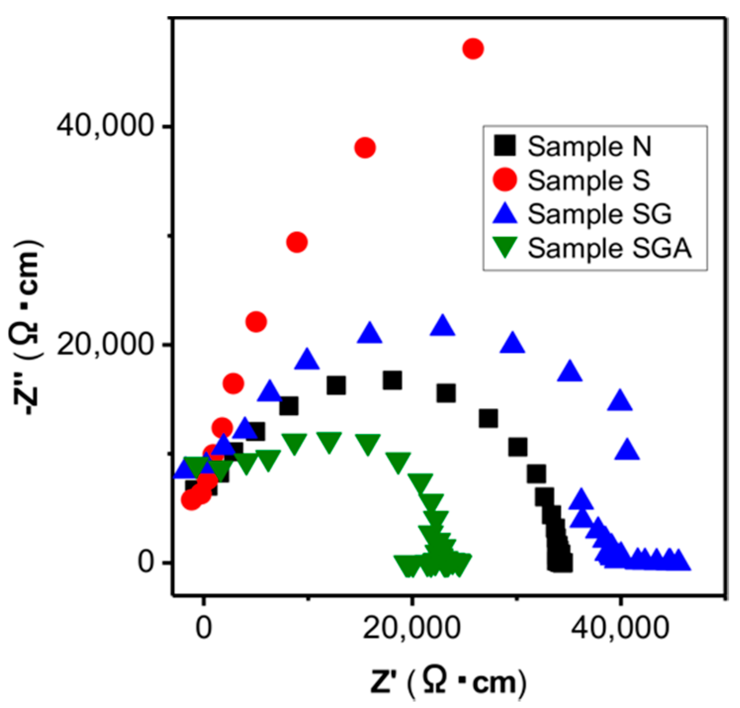
2.3.2. Impedance Measurement

We measured the impedance of Samples N, S, SG and SGA by using an impedance analyzer (Z Hightester 3531, HIOKI, Nagano, Japan). In the impedance measurement, the surfaces of the samples were coated with gold by sputtering method and thus treated samples were used as electrodes. During the measurements, frequency range was controlled from 100 Hz to 5 MHz and measurement temperature was controlled at 25 °C.

3. Results and Discussion

3.1. Material Analyses

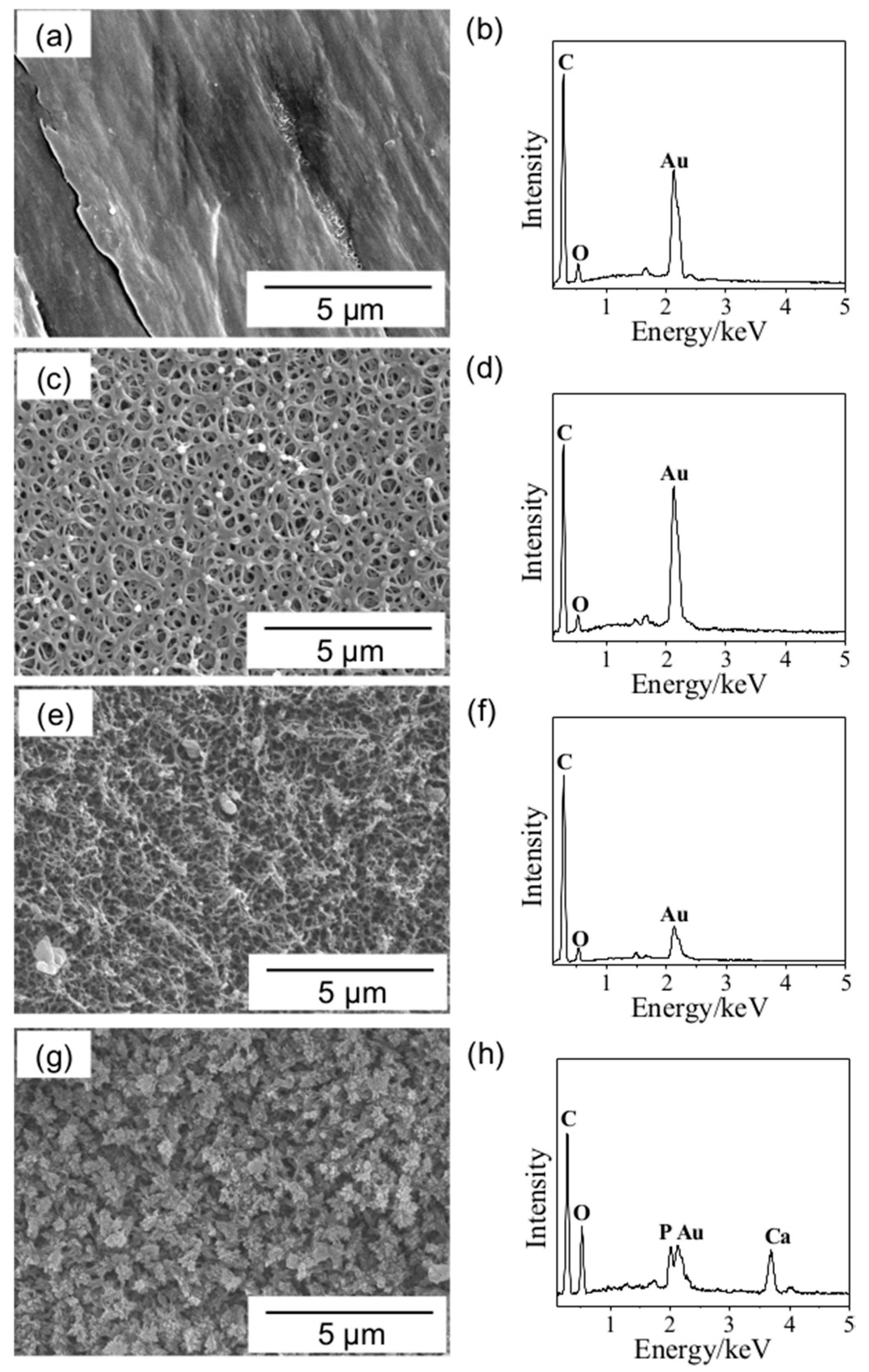
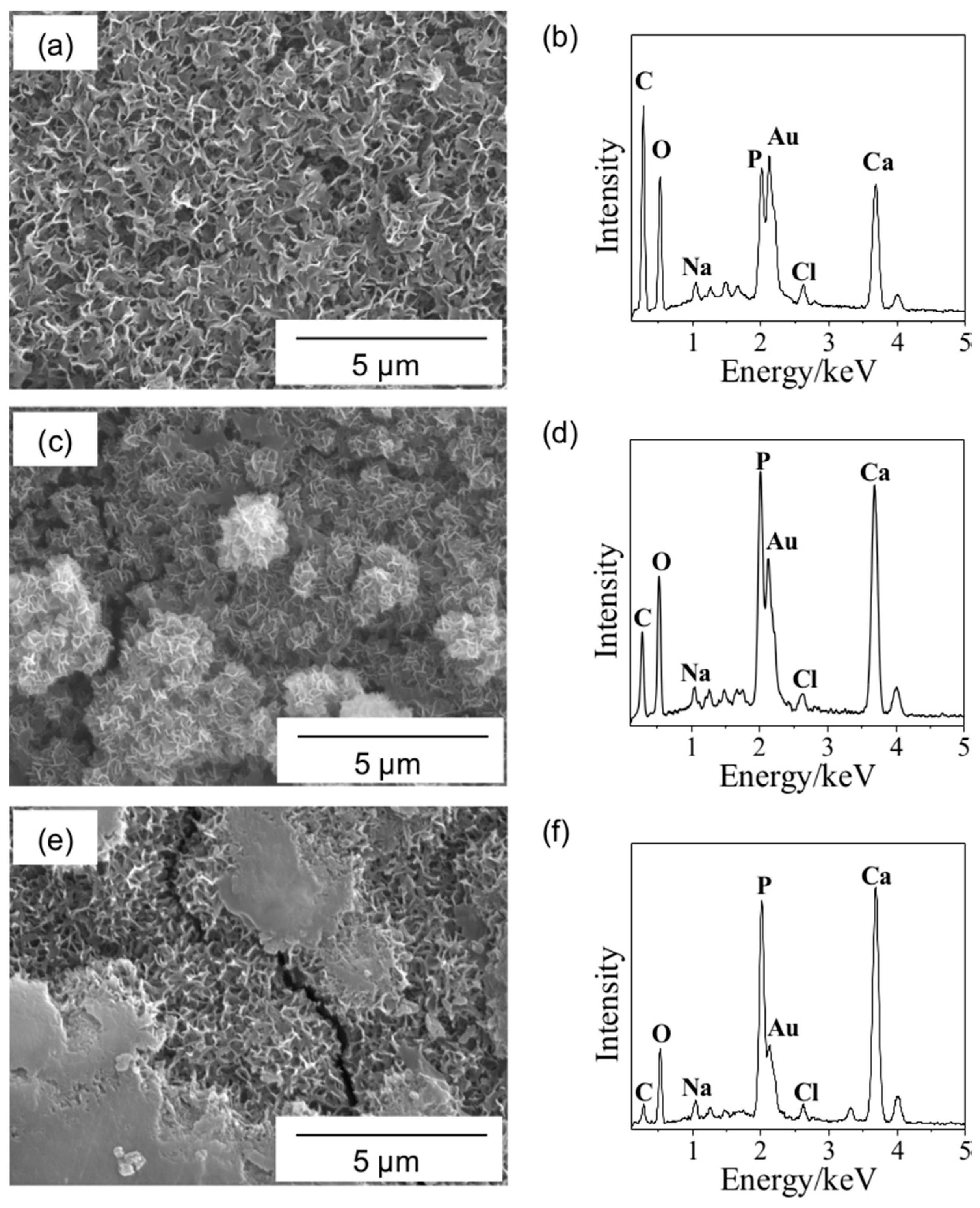
3.1.1. Changes in Surface Morphology during the Fabrication Process

Figure 1a,b shows the SEM micrograph and the EDX profile of the surface of Sample N, which is the untreated CNT-PEEK. Although there were scratches due to the polishing process, the surface morphology was almost flat. By the EDX, peaks of C and O were observed. The peak of Au derived from the gold coating for the observation was also observed.
Figure 1c,d shows a SEM micrograph and the EDX profile of the surface of Sample S, which is the sulfuric acid-treated CNT-PEEK. In comparison with the Sample N, morphological changes are clearly observed on the surface of Sample S. Fine reticulated pores with ca. 500 nm in diameter were formed on the entire surface. The shape of the reticulated pores formed in this study were similar to those formed on pure PEEK, carbon fiber reinforced PEEK and glass fiber reinforced PEEK in our previous studies [12,13,14]. Hence, it is considered that kind of materials contained in a PEEK matrix does not affect the pore formation. These results suggest that the reticulated pores were formed by the reaction of the PEEK. The EDX profile was almost similar to that of Sample N.
Figure 1e,f shows a SEM micrograph and the EDX profile of the surface of Sample SG, which is the sulfuric acid and subsequent oxygen plasma-treated CNT-PEEK. The reticulated pores formed by sulfuric acid treatment were broken after the oxygen plasma treatment. It is considered that the heat of the oxygen plasma caused such a morphological change. The EDX profile was almost similar to that of the Samples N and S.
Figure 1g,h shows a SEM micrograph and the EDX profile of the surface of Sample SGA, which is the sulfuric acid, oxygen plasma and subsequent alkaline SBF-treated CNT-PEEK. Precipitation of a large number of fine particles were observed on the entire surface of the substrate. Furthermore, peaks of P and Ca were newly detected in the EDX profile. Therefore, it is thought that the fine particles consisted of calcium phosphate. In other words, the apatite nuclei were formed on the surfaces of the substrate similar to the case of our previous studies [12,13,14]. As the pH of the solution rises, calcium phosphate formation proceeds due to chemical equilibrium (10Ca2+ + 6PO43− + OH = Ca10(PO4)6OH2). In this study, furthermore, the experimental temperature (70.0 °C) was higher than the physiological temperature (36.5 °C). Hence, it is considered that the reaction of calcium phosphate formation was accelerated, and its nucleation was promoted.

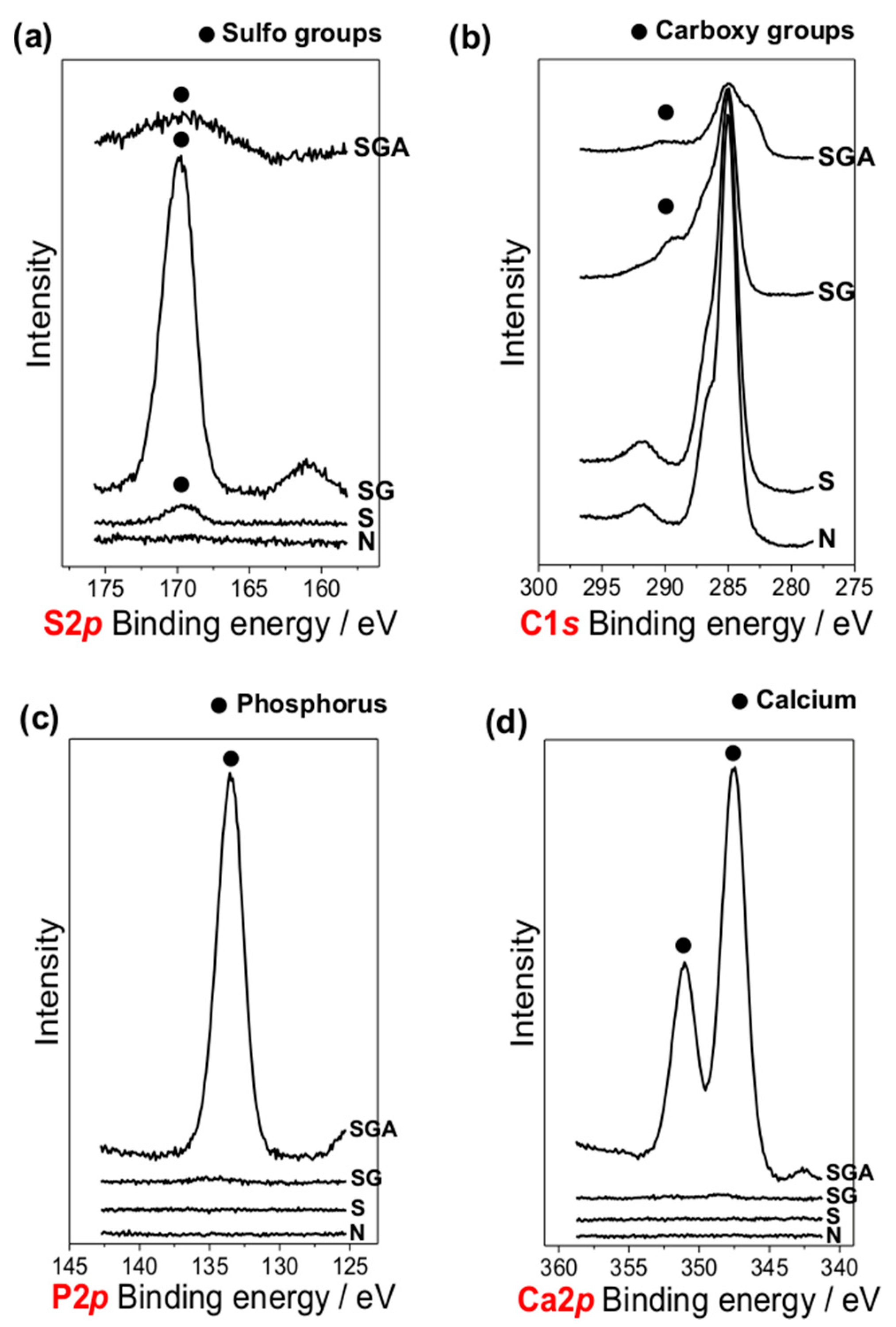
3.1.2. Changes in Functional Groups during the Fabrication Process

Figure 2a shows the XPS narrow spectra around the binding energy of S2p of Samples N, S, SG and SGA. For Sample N, no peaks were observed. For Sample S, a peak derived from sulfo groups was confirmed.
It is well known that aromatic compounds are sulfonated by the reaction with sulfuric acid [19]. Hence, it is considered that aromatic groups in PEEK reacted with sulfuric acid and sulfonation occurred. Interestingly, the sulfo group peak was significantly intensified in Sample SG. Such a result was also obtained for pure PEEK in our previous study [14]. It is speculated that such an increase of sulfo groups is related with oxidation reactions of sulfone-related components near the surface generated during the sulfuric acid treatment because abundant oxygen was supplied around the samples in the oxygen plasma treatment. For Sample SGA, the intensity of the sulfo groups peak decreased because the apatite nuclei were precipitated on the entire surface area of the substrate by the alkaline SBF treatment.
Figure 2b shows the XPS narrow spectra around the energy of C1s of Samples N, S, SG and SGA. For Samples SG, a slight peak derived from carboxy groups was detected. It is considered that the PEEK matrix was oxidized by the oxygen plasma. For Sample SGA, the intensity of the carboxy groups peak decreased because the apatite nuclei were precipitated on the entire surface area of the substrate by the alkaline SBF treatment.
Figure 2c,d shows the XPS narrow spectra around the binding energy of P2p and Ca2p of Samples N, S, SG and SGA. For Samples N, S and SG, no peaks were observed. For Sample SGA, peaks derived from phosphorus and calcium were clearly observed, indicating that apatite nuclei were precipitated on the surface of the substrate by the alkaline SBF treatment.

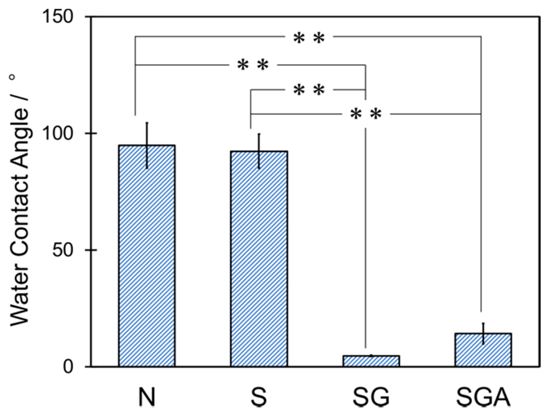
3.1.3. Hydrophilicity

Figure 3 shows the water contact angles of Samples N, S, SG and SGA. By applying one-way ANOVA followed by the Tukey’s tests, Samples N (94.8° ± 9.7° for three samples) and S (92.7° ± 7.3° for three samples) did not show a statistically significant (p > 0.05) difference in water contact angle among each other. In addition, Samples SG (4.7° ± 0.3° for three samples) and SGA (94.8° ± 9.7° for three samples) also did not show a significant difference between each other (p > 0.05). In contrast, the values of Samples SG or SGA showed significantly lower contact angles than Samples N or S (p < 0.01). It was shown that the surfaces of Samples N and S, whose fabrication process did not include oxygen plasma treatment, were hydrophobic and those of Samples SG and SGA, whose fabrication process included oxygen plasma treatment, were super-hydrophilic. Such result was also obtained for pure PEEK in our previous study [14]. It is considered that the super hydrophilicity of Samples SG and SGA was caused by the introduction of carboxy groups and a significant increase of the sulfo groups during oxygen plasma treatment.

3.2. Evaluation of Material Properties

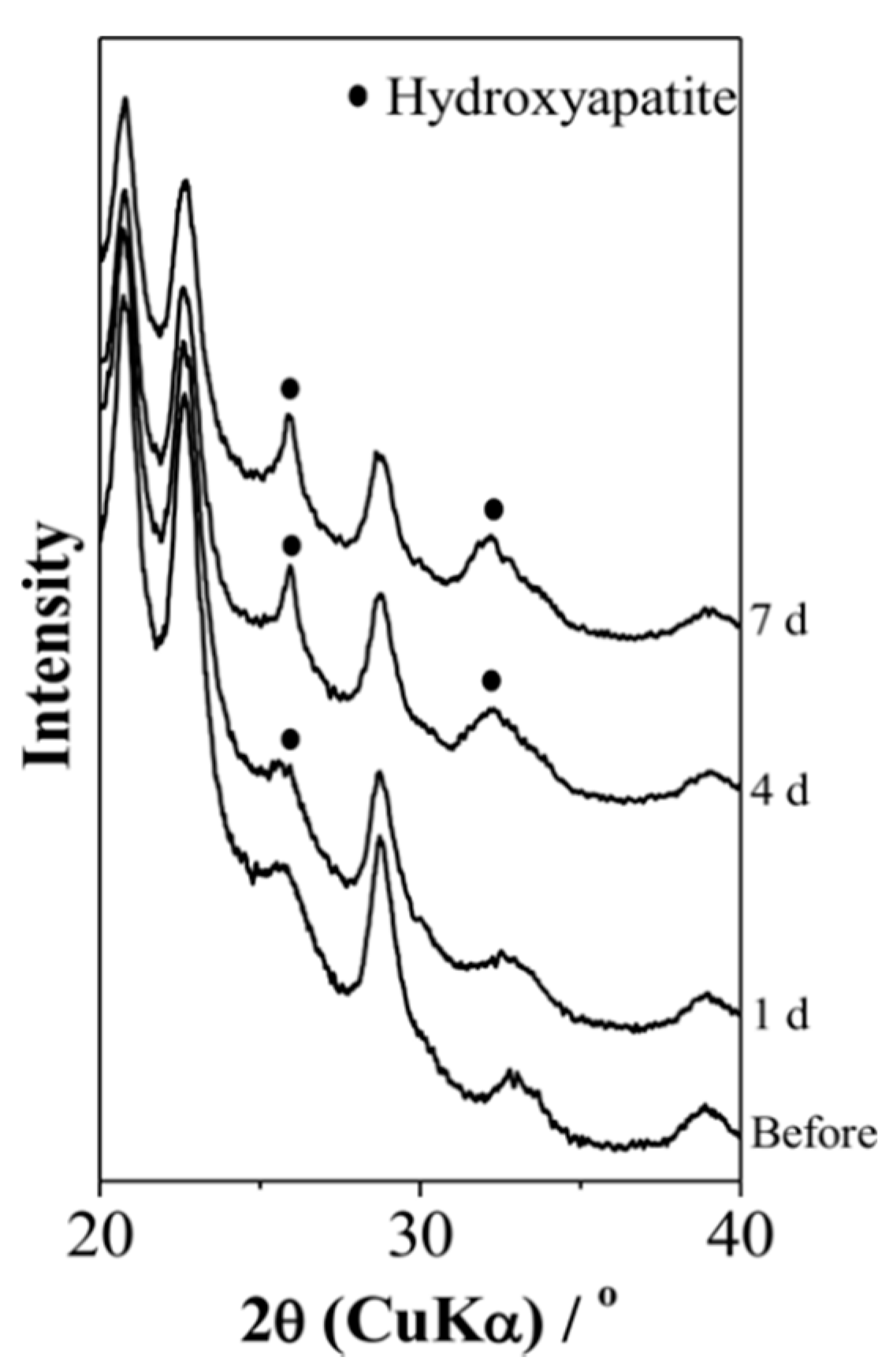
3.2.1. Apatite-Forming Ability

Figure 4 shows the TF-XRD profiles of Sample SGA before and after immersion in SBF for 1, 4 and 7 days, respectively. Before the immersion in SBF, apatite peaks were not detected. After immersing in SBF for 1 day, a slight apatite peak was detected around 26°. Moreover, the intensity and number of apatite peaks intensified after 4 and 7 days as the immersion time increased. This means that apatite nuclei induced apatite formation in SBF within 1 day and the induced apatite grew with increasing immersion time.
Figure 5 shows SEM micrographs and the EDX profiles of the surfaces of the Sample SGA after immersion in SBF for 1, 4 and 7 days. After the immersion in SBF, a film consisting of flake-like crystallites, characteristic of apatite formed in SBF, so-called ‘bone-like apatite’, covered the entire surfaces of the samples and strong peaks of P and Ca were detected. This result indicates that apatite formation was induced on the entire surface of the Sample SGA within 1 day in SBF. Table 1 shows the elemental composition of the surface of Sample SGA after immersion in SBF for each period calculated from the EDX profiles shown in Figure 5. It was verified that the atomic ratios of Ca, P and O, the constituents of apatite, were increased and that of C, the constituent of CNT-PEEK, decreased as the immersion period was extended. This means that once formed the apatite grew on the surface of the substrate in SBF. In addition, it is considered that other detected elements were derived from minute components inserted in crystal structures of apatite or contaminations attached on the surface of the samples because the atomic ratios were very minute in comparison with C, O, Ca and P and their changes could not show a clear increasing or decreasing tendency depending on the immersion period. Zhao et al. reported that sulfuric acid-treated PEEK showed apatite-forming ability in SBF within 28 days [4]. Miyazaki et al. reported that sulfuric acid and calcium chloride-treated PEEK showed apatite-forming ability in SBF within 14 days [5]. In this study, the induction period of apatite formation was within 1 day. Hence, it is confirmed that the apatite nuclei on the surface of CNT-PEEK largely contribute to the effective acceleration of apatite formation.
The adhesive strength of the apatite layer formed by immersion in SBF for 14 days was 8.8 ± 5.0 MPa for five samples. In a previous study, we reported that the adhesive strength of the apatite layer in the case of pure PEEK, carbon fiber-reinforced PEEK and glass fiber reinforced PEEK were 6.6 ± 1.5 MPa for 12 samples, 7.7 ± 0.9 MPa for 11 samples and 6.7 ± 1.8 MPa for seven samples, respectively [12,13]. Although one-way ANOVA followed by the Tukey’s tests was carried out between the CNT-PEEK investigated in this paper and the above other types of PEEK reported in our previous papers, significant differences were not observed among them (p > 0.05). Hence, it is considered that the CNT-PEEK statistically showed almost a similar level of adhesive strength in comparison with other types of PEEK composite. It is considered that such adhesive strength was attained by a mechanical interlocking effect between apatite inside the pores and the CNT-PEEK substrate, like in our previous study.

3.2.2. Impedance

Figure 6 shows the Nyquist plots of Samples N, S, SG and SGA. The impedance of Sample S was considerably larger than that of Sample N and the impedance was increased by the sulfuric acid treatment. It is considered that the number of CNTs near the surface of the substrate was decreased by the sulfuric acid treatment. The impedance of Sample SG was smaller than that of Sample S and the impedance was decreased by the oxygen plasma treatment. It is considered that CNTs existing inside the substrate were newly exposed by the changes in the surface morphology caused by the heat of the oxygen plasma. The impedance of Sample SGA was the smallest among these sample conditions. Interestingly, the impedance of Sample SGA was smaller than that of Sample N and it was suggested that the electrical conductivity was improved after the series of surface modifications. It is speculated that the apatite nuclei precipitated by the alkaline SBF treatment might possess an ionic conductivity slightly because of their extremely low crystallinity.
We acknowledge several limitations in this study. First, we have not conducted animal tests yet. It is well known that SBF test can predict bone-bonding ability well [7], however, some researchers have pointed out several exceptions of the relationship between apatite-forming ability in SBF and bone-bonding ability in vivo [20]. For clinical applications, hence, it is essential to evaluate bone-bonding ability of this material by animal tests. About this point, however, we have obtained expected results in animal test when we applied similar fabrication methodology to pure PEEK [14]. Hence, we consider that also this material has a potential to exhibit similar osteoconductivity in vivo. Second, we have not conducted cell activity tests yet. Especially for biosensing applications, a comparative evaluation of cell responses on the surface of the substrate is essential. Third, we have not evaluated the relationship between amount of apatite nuclei on the substrate and the impedance of the substrate and have not optimized the conductivity required in biosensing applications yet. Finally, we carried out the impedance tests only in normal air circumstances in this study. Taking into consideration possible biosensing applications, evaluation in a humid or a cell environment is required. These points will be addressed in our future studies.

4. Conclusions

We successfully imparted apatite-forming ability to CNT-PEEK by the following three steps: First a sulfuric acid treatment to form fine pores, second an oxygen plasma treatment to improve the hydrophilicity and lastly an alkaline SBF treatment to form apatite nuclei. Thus-obtained samples were coated with hydroxyapatite within 1 day in SBF and showed high apatite-forming ability. The apatite film formed in SBF showed sufficient adhesive strength by a mechanical interlocking effect. Moreover, the treated CNT-PEEK showed a small impedance in comparison with the untreated CNT-PEEK and possessed electrical conductivity. This material is expected to be a new type of biomaterial with both biological and electrical properties, useful in the orthopedic and biosensing fields.

Author Contributions

Conceptualization, C.I. and T.Y.; Data curation, C.I.; Formal analysis, C.I. and T.Y.; Funding acquisition, T.Y.; Investigation, C.I. and T.Y.; Methodology, T.Y.; Project administration, T.Y.; Supervision, T.Y. and S.T.; Validation, C.I., T.Y. and S.T.; Writing—Original Draft, C.I.; Writing—Review and editing, T.Y. All authors have read and agreed to the published version of the manuscript.

Funding

This study was partly funded by JSPS KAKENHI (16K16401 and 19H02442), Murata Science Promotion Foundation Research Grant, and Kyoto University Research and Development Program “Ishizue”.

Conflicts of Interest

The authors declare no conflict of interest.

References

  1. Kurtz, S.M. An Overview of PEEK Biomaterials. In PEEK Biomaterials Handbook, 2nd ed.; Kurtz, S.M., Ed.; Elsevier: Amsterdam, The Netherlands, 2019; pp. 3–9. [Google Scholar]
  2. Kizuki, T.; Matsushita, T.; Kokubo, T. Apatite-forming PEEK with TiO2 surface layer coating. J. Mater. Sci.-Mater. Med. 2015, 26, 5359. [Google Scholar] [CrossRef]
  3. Shimizu, T.; Fujibayashi, S.; Yamaguchi, S.; Yamamoto, K.; Otsuki, B.; Takemoto, M.; Tsukanaka, M.; Kizuki, T.; Matsuhita, T.; Kokubo, T.; et al. Bioactivity of sol-gel-derived TiO2 coating on polyetheretherketone: In vitro and in vivo studies. Acta Biomater. 2016, 35, 305–317. [Google Scholar] [CrossRef] [PubMed] [Green Version]
  4. Zhao, Y.; Wong, H.M.; Li, P.; Xu, Z.; Chong, E.Y.W.; Yan, C.H.; Yeung, K.W.K.; Chu, P.K. Cytocompatibility, osseointegration, and bioactivity of three-dimensional porous and nanostructured network on polyetheretherketone. Biomaterials 2013, 34, 9264–9277. [Google Scholar] [CrossRef] [PubMed]
  5. Miyazaki, T.; Matsunami, C.; Shirosaki, Y. Bioactive carbon–PEEK composites prepared by chemical surface treatment. Mater. Sci. Eng. C 2017, 70, 71–75. [Google Scholar] [CrossRef] [PubMed]
  6. Kokubo, T.; Kushitani, H.; Sakka, S.; Kitsugi, T.; Yamamuro, T. Solutions able to reproduce in vivo surface-structure changes in bioactive glass-ceramic A-W. J. Biomed. Mater. Res. 1990, 24, 721–734. [Google Scholar] [CrossRef] [PubMed]
  7. Kokubo, T.; Takadama, H. How useful is SBF in predicting in vivo bone bioactivity? Biomaterials 2006, 27, 2907–2915. [Google Scholar] [CrossRef] [PubMed]
  8. Takadama, H.; Kokubo, T. In vitro evaluation of bone bioactivity. In Bioceramics and Their Clinical Applications; Kokubo, T., Ed.; Woodhead Publishing: Cambridge, UK, 2008; pp. 165–182. [Google Scholar]
  9. Implants for Surgery—In Vitro Evaluation for Apatite-Forming Ability of Implant Materials; ISO 23317; International Organization for Standardization: Geneva, Switzerland, 2014.
  10. Yao, T.; Hibino, M.; Yamaguchi, S.; Okada, H. Method for Stabilizing Calcium Phosphate Fine Particles, Process for Production of Calcium Phosphate Fine Particles by Utilizing the Method, and Use Thereof. U.S. Patent 8178066, 15 May 2012. Japanese Patent 5261712, 10 May 2013. [Google Scholar]
  11. Yao, T.; Yabutsuka, T. Material Having Pores on Surface, and Method for Manufacturing Same. Japanese Patent 6071895, 13 January 2017. [Google Scholar]
  12. Yabutsuka, T.; Fukushima, K.; Hiruta, T.; Takai, S.; Yao, T. Effect of pores formation process and oxygen plasma treatment to hydroxyapatite formation on bioactive PEEK prepared by incorporation of precursor of apatite. Mater. Sci. Eng. C 2017, 81, 349–358. [Google Scholar] [CrossRef] [PubMed]
  13. Yabutsuka, T.; Fukushima, K.; Hiruta, T.; Takai, S.; Yao, T. Fabrication of bioactive fiber-reinforced PEEK and MXD6 by incorporation of precursor of apatite. J. Biomed. Mater. Res. B Appl. Biomater. 2018, 106, 2254–2265. [Google Scholar] [CrossRef] [PubMed]
  14. Masamoto, K.; Fujibayashi, S.; Yabutsuka, T.; Hiruta, T.; Otsuki, B.; Okuzu, Y.; Goto, K.; Shimizu, T.; Shimizu, Y.; Ishizaki, C.; et al. In vivo and in vitro bioactivity of a “precursor of apatite” treatment on polyetheretherketone. Acta Biomater. 2019, 91, 48–59. [Google Scholar] [CrossRef] [PubMed]
  15. Lacefield, W.R. Hydroxyapatite coatings. In An Introduction to Bioceramics, 2nd ed.; Imperial College Press: London, UK, 2013; pp. 331–347. [Google Scholar]
  16. Kim, H.-M.; Miyaji, F.; Kokubo, T.; Nakamura, T. Bonding strength of bonelike apatite layer to Ti metal substrate. J. Biomed. Mater. Res. 1997, 38, 121–127. [Google Scholar] [CrossRef]
  17. Miyazaki, T.; Kim, H.-M.; Kokubo, T.; Ohtsuki, C.; Kato, H.; Nakamura, T. Enhancement of bonding strength by graded structure at interface between apatite layer and bioactive tantalum metal. J. Mater. Sci. Mater. Med. 2002, 13, 651–655. [Google Scholar] [CrossRef]
  18. Juhasz, J.A.; Best, S.M.; Kawashita, M.; Miyata, N.; Kokubo, T.; Nakamura, T.; Bonfield, W. Bonding strength of the apatite layer formed on glass-ceramic apatite-wollastonite-polyethylene composites. J. Biomed. Mater. Res. A 2003, 67, 952–959. [Google Scholar] [CrossRef]
  19. Solomons, T.W.G.; Fryhle, C.B. Reactions of Aromatic Compounds. In Organic Chemistry, 7th ed.; Wiley: New York, NY, USA, 2000; pp. 661–713. [Google Scholar]
  20. Kawashita, M.; Hayashi, J.; Li, Z.; Miyazaki, T.; Hashimoto, M.; Hihara, H.; Kanetaka, H. Adsorption characteristics of bovine serum albumin onto alumina with a specific crystalline structure. J. Mater. Sci. Mater. Med. 2014, 25, 453–459. [Google Scholar] [CrossRef] [PubMed] [Green Version]
Figure 1. (a,c,e,g) SEM micrographs and (b,d,f,h) EDX profiles of the surfaces of (a,b) Sample N, (c,d) Sample S, (e,f) Sample SG, (g,h) Sample SGA.
Coatings 10 00191 g001
Figure 2. XPS narrow spectra around binding energy of (a) S2p, (b) C1s, (c) P2p and (d) Ca2p on the surface of Samples N, S, SG and SGA.
Coatings 10 00191 g002
Figure 3. Water contact angle on the surface of Samples N, S, SG and SGA. The symbol ‘**’ indicates p < 0.01 and the no symbol indicates p > 0.05 by one-way ANOVA followed by the Tukey’s tests.
Coatings 10 00191 g003
Figure 4. TF-XRD profiles of on the surface of Sample SGA before and after immersion in SBF for 1 day, 4 days and 7 days.
Coatings 10 00191 g004
Figure 5. (a,c,e) SEM micrographs and (b,d,f) EDX profiles of the surface of Sample SGA after immersion in SBF for (a,b) 1 day, (c,d) 4 days and (e,f) 7 days.
Coatings 10 00191 g005
Figure 6. Nyquist plots of Samples N, S, SG and SGA.
Coatings 10 00191 g006
Table 1. Elemental composition of the surface of Sample SGA after immersion in SBF for each period calculated from the EDX profiles shown in Figure 5 (except Au generated by sputtering).
ElementElemental Composition/at%
1 Day4 Days7 Days
C61.62340.38621.384
O32.30040.68343.106
Ca2.73011.58621.458
P2.1816.62111.429
Na0.6620.4521.213
Mg0.1720.0170.177
Cl0.1640.2310.517
K0.0010.0010.715
Al0.1660.0020.002
Si0.0010.0200.002

