Article

Strain-Induced Cracking Behavior of Coating/Substrate Systems and Strain Tolerant Design for Thick Coatings

1
State Key Laboratory for Mechanical Behavior of Materials, School of Materials Science and Engineering, Xi’an Jiaotong University, Xi’an 710049, China
2
School of Materials Science and Engineering, South China University of Technology, Guangzhou 510006, Guangdong, China
*
Author to whom correspondence should be addressed.
Coatings 2020, 10(11), 1066; https://doi.org/10.3390/coatings10111066
Submission received: 24 September 2020 / Revised: 16 October 2020 / Accepted: 27 October 2020 / Published: 6 November 2020

Abstract

:
The life span for a coating attached to its substrate is basic support for their desired protective function. Therefore, it is necessary to find out the causes responsible for the failure of coatings during service. This paper developed a finite element model to investigate the cracking behavior of plasma-sprayed ceramic coatings induced by the mismatch strain of thermal expansion between coating and substrate. Crack propagation affected by coating thicknesses was realized by the virtual crack closure technique (VCCT). The residual stresses (σ22 and σ12) and the strain energy release rate (SERR) induced at the tip of pre-crack in ceramic coatings are calculated. Results show that the σ22 and σ12 at the tip of the pre-crack increases continuously with the thickening ceramic coatings. The SERRs at the tip of the pre-crack in top-coat (TC) were increased with the thickness of ceramic coatings, resulting in the propagation of cracks. The crack length increases with the thickening of ceramic coatings. The crack propagation and coalescence lead to coating spallation, which is one of the main failure modes for plasma sprayed ceramic coatings during service. Given that, strain tolerant design was developed by inserting vertical pores in coatings. It was found that the SERRs were decreased with the increase in the number of vertical pores, as well as their depth. Moreover, the coatings with vertical pores appear to be crack-resistant, in particular for the thicker coatings. This suggests that the strain tolerant design is helpful to extend the life span of thick coatings, which makes a fundamental contribution to the design and preparation of advanced protective coatings in future applications.

Graphical Abstract

1. Introduction

Ceramic coatings are often used to protect metallic substrate for desired functions, in particular for high-temperature-related fields, such as thermal barrier coatings (TBCs) and radar-absorbing coatings [1,2,3]. The coating thickness can be 200 µm–3 mm [4,5]. As one of the widely-used ceramic protective coatings, TBCs are advanced materials system generally used for many years to protect the metallic components of the gas turbine engine—such as nozzles, turbine blades, combustors, and vanes that undergo hot gases—thus the temperature of the substrate surface can be significantly lowered [6,7,8,9,10]. TBCs with a thickness of 200 µm–1 mm serve to insulate the engine’s components from high and large-time heat loads [11]. As a result, the TBCs are used to attain greater functioning temperatures [12], which are highly needed for higher efficiency [13] and thrust–weight ratios. Therefore, the demand to coat turbine blades with TBCs becomes greater and greater with the continuous increase of working temperature at hot section of turbine blades. The TBCs will play an increasingly significant role in controlling the gas with elevated temperature corroding against the outside of turbine sharp edges, and coated TBCs will enable the turbine sharp edges working at elevated temperature [14,15,16].
Commonly, standard TBCs or radar-absorbing coatings consist of three layers with different materials: (I) substrate (SUB) that is typically made of metallic materials (e.g., nickel- or cobalt-based superalloy) to bear mechanical load [17]; (II) ceramic top coatings (TC) to provide desired function [18]; (III) bond coat (BC, e.g., NiCrAlY or NiCoCrAlY) to enhance bonding between TC and substrate, and to reduces the resultant oxidation [19,20]. Besides, a layer of thermally grown oxide (TGO) is often formed during thermal service [21,22]. The thermal, physical and mechanical properties of all layers are different which are emphatically influenced by the handling conditions [23,24]. During construction and utilization, these layers interact mechanically and chemically. This energetic connection of layers controls the strength of coatings. It should be noted that during service, the microstructures and composition of layers incessantly change [17]. The thermal spraying process is one of the most efficient and cost-effective techniques for improving the surface properties of components, structures, and parts. For many years, a large number of thermal spraying techniques —such as atmospheric plasma spraying (APS), vacuum plasma spraying (VPS), high-velocity oxygen fuel (HVOF), detonation gun spraying (DGS), and wire arc spraying (WAS)—were successfully developed to produce coatings [25,26,27]. Among various thermal spraying techniques, APS has been used prominently in industrial applications because of its low maintenance cost, operations simplicity, a wide range of feedstock materials, and the possibility of deposition of relatively thick coating up to 2 mm [26]. Generally, the TC are deposited by either atmospheric plasma spraying (APS) or electron beam physical vapor deposition (EB-PVD) [28,29,30,31,32]. Normally, APS ceramic coatings exhibit a lamellar structure [33,34], which is aligned parallel to the substrate surface. The micro-cracks and micro-pores in ceramic TC are randomly distributed and lead to low thermal conductivity of APS-TBCs. The one crack meets with a neighboring crack. The crack coalescence leads to the coating spallation, which is responsible for the ultimate failure of TBCs [35]. In contrast, TCs deposited by EB-PVD have columnar grains structural characteristics [36,37], which aligned perpendicular to the substrate. The vicinal columnar grains are inclined with one another. Usually, these columnar-structured TBCs with higher strain tolerance due to lower elastic modulus can enhance their thermal-shock resistance [38,39] that prolongs the thermal life of coatings [28,40,41,42,43,44]. As the ceramic coatings were typically applied at worst service conditions, spallation, or delamination phenomenon at an early stage is unavoidable. The short lifespan and service execution are normally drawbacks for APS ceramic coatings. This problem would be even worse for thicker radar-absorbing coatings, which often have a thickness of 1–3 mm.
Based on an idealized model, the structural parameters affected the properties of the TCs, such as Young’s modulus, fracture toughness, and thermal conductivity [45,46]. In APS coatings, a continuous network of cracks can form, which is ascribed to the connectivity of intra-splat cracks and inter-splat pores. In coatings, this crack network leads to a result that the crack can propagate in any directions [47,48]. Especially, the inter-splat cracks are propagated easily due to large stress between adjacent splats even if the splat growth occurs [33,49,50]. The sintering of TC at elevated temperature has a harmful effect on the failure of the coating when it is subjected to thermal shock loading. The effect of sintering on the delamination of lamellar TCs was investigated, which suggested many effective design methods for a greater thermal cyclic lifetime [37,51]. To enhance the spalling resistance of TBCs, many efforts have been done, such as developing new materials [52] and design multi-layered coatings [12,34,53].
The failure of APS ceramic coatings generally occurs through spallation which is due to the growth of crack along with the lamellar interface and following coalescence of crack [54,55,56,57]. However, during service conditions, the behaviors of crack propagation and coalescence responsible for the main failure modes have not been precisely understood. Consequently, it is very difficult to further understand the short life span of TBCs and to suggest some reasonable coating optimization methods. The failure tendency and failure modes of TBCs are often judged by the magnitude of maximum stress and deriving force. The research methods are mostly static. Crack growth/fracture in which layers are dissociated from one another, or material is damaged due to external load. With the build out of finite element modeling (FEM) [58], many methods such as: virtual crack closure technique (VCCT), cohesive zone model (CZM), extended finite element method (XFEM), and conventional finite element method (CFEM) can be used to simulate the behavior of crack propagation [59,60,61,62]. Among various methods, VCCT has been used prominently to investigate the dynamic failure behavior of coatings. Because VCCT is very suitable to calculate the SERR (or J integral) during the crack propagation based on the thought that the necessary energy when the crack propagates a tiny displacement is equal to the work of making the crack closed [62].
This study mainly focuses on two aspects. On one hand, the dominant parameters on the spallation of APS ceramic coatings were investigated by a finite element model, to understand the cracking propagation during service. On the other hand, a strain-tolerant design for APS ceramic coatings was proposed to enhance its crack-resistance, to extend the life span for thick coatings.

2. Model Development

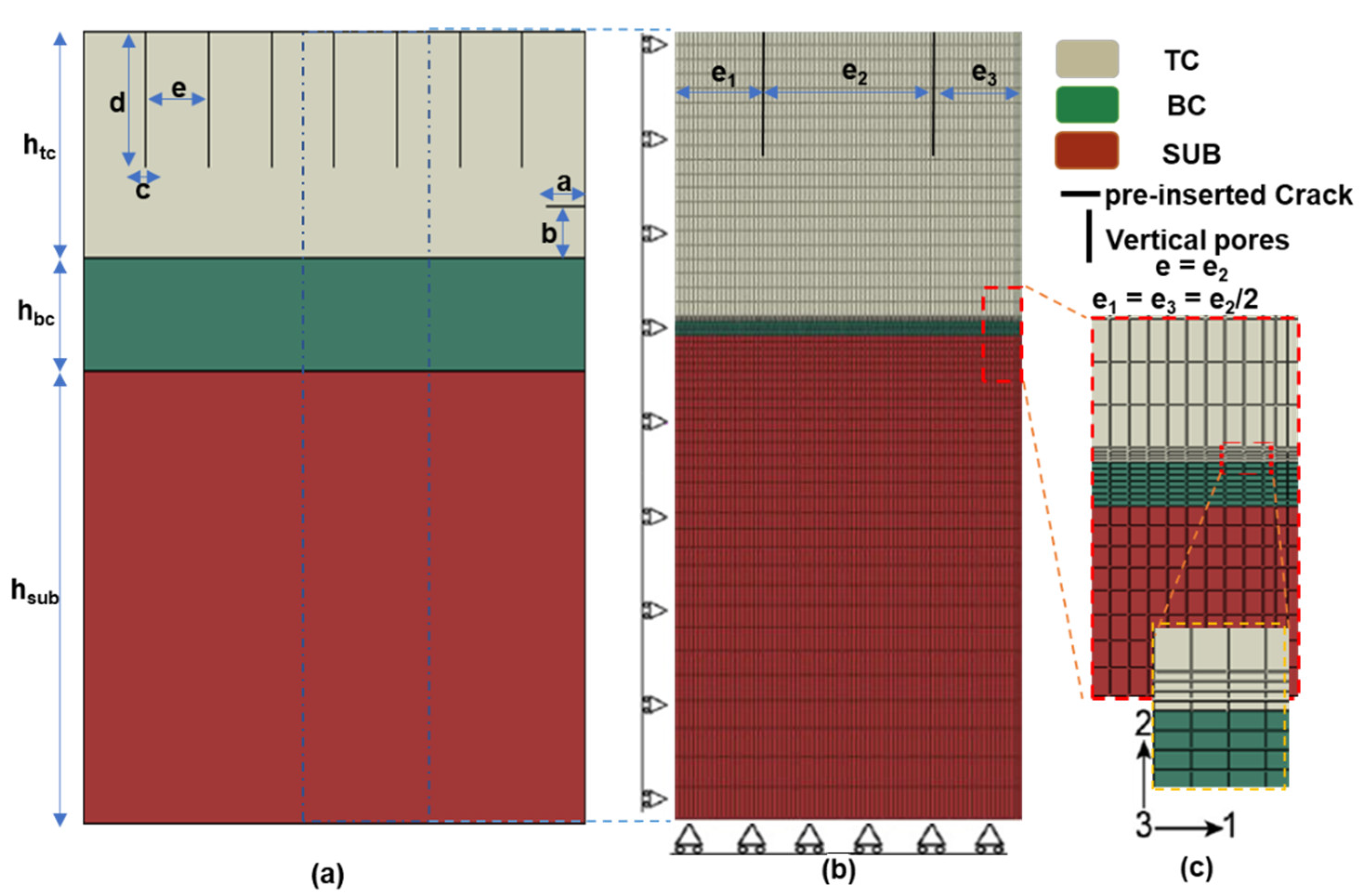
2.1. Geometry of Model

The TBC system, which is made up of TC, BC, and SUB, was used to investigate the crack propagation in TC. In this paper, the FEM software package ABAQUS (Version: 6.14-1) [63] is adopted to carry out numerical calculations. Figure 1a shows the whole geometry of the model which is used for finite element analysis (FEA). The length of the model is chosen as 10 mm and the thickness of the substrate and BC are chosen as 5 mm and 150 µm. The effect of TC thickness on crack propagation was investigated here, therefore, the thicknesses of TC were selected to be different. The pre-crack along the coating surface is inserted in the model, as shown in Figure 1a, in this model, a is the crack length and b is the vertical distance from TC/BC interface. In detail, a refers to 100 µm and b is 50 µm.
In this study, models with and without vertical pores were investigated comparatively. For the former case, vertical pores were inserted in TC for strain tolerant design. In this model, c is the width of vertical pores, e is the distance between two vertical pores, and d is the depth of vertical pores. Where htc, hbc, and hsub are the thickness of TC, BC, and Sub, respectively. The width of vertical pores is 5 µm. The influence of the number of vertical pores and depth of vertical pores on crack propagation is also performed here. The model is periodic symmetry; therefore, a representative unit-cell was used for simulation. This horizontal pre-crack shows a series of cracks. Once, this horizontal pre-crack propagates to the left side of the model, it will intersect with the crack in the neighboring region and then coating spallation will occur. The residual stresses will be calculating again due to the effect of crack. The virtual crack closure technique (VCCT) [64], which is based on the fracture mechanics concepts, is used to calculate the strain energy release rate (SERR) at the crack tip. The regular quadrilateral element is used to mesh the model, and the overall mesh model is represented in Figure 1b. The mesh improvement is accomplished near the crack region and interface because of our great interest in this region. The refine mesh in this region is vividly presented in Figure 1c. At the crack tip, the SERR will not be affected by the size of the mesh because the mesh grid is dense enough.

2.2. Boundary Conditions

The current finite element model is based on the following hypotheses: In this model, (1) TC layer aside with a pre-existing crack and all other layers are homogeneous and isotropic. The geometric morphology at the BC/TC interference is flat; (2) The mechanical properties such as the Poisson ratio and Young’s modulus of all layers are listed in Table 1 [65,66,67,68]; (3) The SUB and BC layer behaved as elastic-plastic material, and the TC layer was regarded as elastic behavior [69]. Table 1 shows the properties of the materials used for SUB, BC, and TC. It is worth noting that the properties of the materials were based on typical materials used for TBC.
Since the representative unit a from the coating sample, periodic boundary conditions were used in this study. The periodicity boundary constraint which can be understood by utilizing a multi-point coupling (MPC), is applied on the right edge of the model shown in Figure 1b. Thus, all the nodes located on the edge have similar displacement along direction 1. Simultaneously, all these nodes can move freely along the y-direction. On the left edge of the model, a strain of 0.2% is applied to model the mismatch strain between coating and substrate. Additionally, nodes of the bottom boundary of model are restricted to move along the y-direction, which can stop the incident of rigid-body displacement.

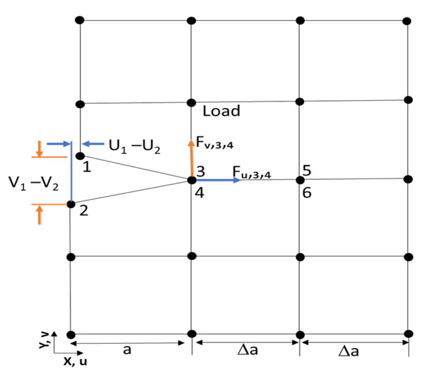
2.3. Modeling Tool Used for Crack Propagation

When the crack growth is simulated in the TC layer, another crack surface must be made once a predetermined criterion is met during the thermal cycling. In ABAQUS [63], by utilizing the “debond” method, the growth of crack can be effectively captured. This crack propagation tool enables the crack to propagate along a fixed way. The virtual crack closure technique (VCCT) method, based on the principles of linear elastic fracture mechanics (LEFM) that was proposed by Rybicki and Kanninen [64], is used to calculate strain energy release rate (SERR) referred to as the crack driving force. With this technique, the components of SERR GI and GII can be effectively obtained.
The VCCT technique is one of the efficient and most popular tools to find the mode-dependent components of SERR GI and GII by using nodal force and displacement. A relatively stiff spring is placed between the node pair at the crack-tip to extract the internal nodal forces, while the node pair behind the crack-tip is utilized to extract the information for displacement openings [35]. The schematic diagram of VCCT for four node elements is shown in Figure 2. The components of SERR GI and GII can be expressed as [35]
G I   =   F v , 3 , 4 Δ v 2 B Δ a   =   F v , 3 , 4 ( v 1 v 2 ) 2 B Δ a
G II   =   F u , 3 , 4 Δ u 2 B Δ a   =   F u , 3 , 4 ( u 1 u 2 ) 2 B Δ a
where GI and GII are the SERR for Mode I and Mode II respectively, and Fν,3,4, and Fu,3,4 are the components of nodal force at crack tip. The vi and ui are the components of nodal displacement behind the crack tip and B is the thickness in third-direction and its value for the two-dimension (2D) model normally equals 1, with unit thickness. In this work, the criterion of crack-propagation for a top-coat layer can be examined by a power law [71], which is expressed as
f = Gequiv/Gequivc = (GI/GIc)am + (GII/GIIc)an
where Gequiv and Gequivc are the equivalents and critical equivalent SERR, GIC and GIIC are the critical SERR for mode I and II respectively, the value, 1.0, is chosen for both am and an. The crack propagation occurs when the parameter f becomes 1.0. When the value 1.0 is chosen for power exponents (am and an) [35,70], the power law stated as
Gequiv/Gequivc = (GI/GIc) + (GII/GIIc)
Once the Gequiv reaches the Gequivc calculated by using the user specified mode-max criterion, the nodes of the crack tip will debond [63]. The fracture toughness of the TC layer reported in previous articles [72,73,74] is in the range of 5 to 15 J/m2. In current research, we presumed GIC = GIIC = 15 J/m2 [35,73] for TC layer. It is noted that the value of critical SERR is surmised to be equivalent for mode (I and II) due to the deficiency of relevant mode-dependent experimental data.

3. Results and Discussion

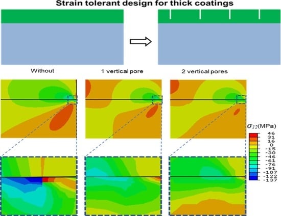
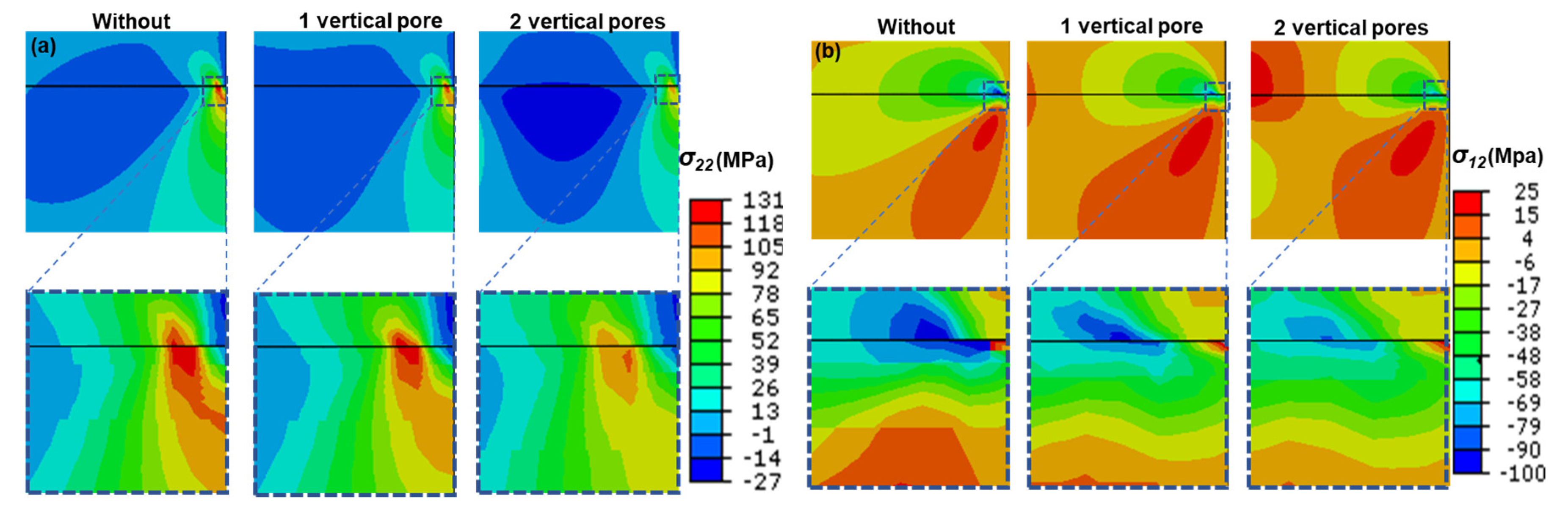
3.1. Stress Distribution in TC with and without Vertical Pores

To investigate the effect of coating thickness on SERR of pre-crack, a very large critical energy release rate (Gequivc) was used for cases with and without vertical pores, the stress distribution in TC layer are primarily investigated to achieve some important data at the tip of pre-crack. Generally, the residual stresses developed in ceramic coating due to the difference of thermal expansion coefficient of elements, which cause the degradation of coatings. The formation of the cracks is usually attributed to the quenching stress and thermal mismatch stress. The detailed of residual stresses can be seen our published paper [4]. The black horizontal line in Figure 3 is the crack path and the point where stress is maximum on the line is the pre-crack tip. Figure 3a,b demonstrate the residual stresses field including σ22 and σ12 at different thickness (3, 2, 1, 0,8, 0.5, and 0.3 mm) of TC. The residual stresses (σ22 = 224 MPa and σ12 = 136 MPa) are very high when the thickness of TC is 3 mm and their values gradually decrease (σ22 = 224 to 56 MPa and σ12 = 136 to 53.6 MPa) when decreasing the thickness of TC up to 0.3 mm. The continuous increase in stresses is necessary to initiate or propagate the crack [66,75]. It means that the crack is easier to extend with a larger thickness of TC.
Figure 4a,b shows that the residual stress distribution (σ22 and σ12) at the crack tip with a very large critical energy release rate (Gequivc), when one vertical pore is inserted into top-coat of thickness 3 mm. The values of residual stresses (σ22 = 332.4 MPa and σ12 = 110.3 MPa) are high when the depth of vertical pore is 0.5 mm and their values decreased with increasing the depth of vertical pore and its value (σ22 = 119.6 MPa and σ12 = 85.5 MPa) when the depth of vertical pore is maximum which is 2.5 mm. When two vertical pores are inserted into TC, the investigation of residual stresses (σ22 and σ12) at the crack tip with very high “Gequivc” as shown in Figure 5a,b. From Figure 5a,b, the values of σ22 = 321 MPa and σ12 = 109 MPa are very high when the depth of vertical pores is minimum (0.5 mm). The values of σ22 = 85.5 MPa and σ12 = 78 MPa decreased with increasing the depth of vertical pores up to 2.5 mm. These results indicate that the ceramic coating with vertical pores has a lower value of residual stresses compared to ceramic coating without vertical pores, as reported in the literature [4,76].
Figure 6a,b, Figure 7a,b, and Figure 8a,b show the stress distribution (σ22 and σ12) at the pre-crack tip with very high critical strain energy release rate for different thickness (3, 2 and 1 mm) of TC without, with one vertical pore and with two vertical pores. The values of σ22 (224, 185, and 129.3 MPa) and σ12 (136, 99.8, and 83 MPa) at the crack tip are very high in TC of a thickness (3, 2, and 1 mm) without vertical pores, respectively. Their values (σ22 = 119.6, 132.6, and 121 MPa) and σ12 = 85.5, 84, and 82.9 MPa) decreased when one vertical pore was inserted into TC and their value (σ22 and σ12) decreased further from (119.6 to 85.5 MPa, 132.6 to 89.4 MPa depends, and 121 to 104 MPa) and from (85.5 to 78 MPa, 84 to76 MPa, and 82.9 to 75.6 MPa) when two vertical pores insert into TC of a thickness (3, 2, and 1 mm), respectively. The value of σ22 and σ12 further decreased by decreasing the thickness of TC.
Figure 9 exhibits the evolution of stresses in the TC with 3, 2, 1, 0.8, 0.5, and 0.3 mm thickness along the perspective cracking path in top-coat. It is found that the stress σ22 at the crack tip is maximum (224 MPa) when the thickness of TC is 3 mm and the stress magnitude continuously decrease up to 56 MPa at the crack tip with decreasing the thickness of TC up to 0.3 mm as shown in Figure 9a. From Figure 9b a similar trend can be observed for stress σ12. The continuous increase in stress is necessary to initiate or spread the crack [66]. The variation of stress σ22 and σ12 at the crack tip in Figure 9 is the function of TC thickness.
Figure 10 shows the stress distribution in topcoat when one vertical pore and two vertical pores were inserted into 3, 2, and 1 mm TC thickness with different depth, along the crack path in TC. The stress (σ22, σ12) at the pre-crack tip is maximum when the depth of the vertical pore is minimum and the value of stress continuously decreases with increasing the depth of the vertical pore at same thickness (3, 2, and 1 mm) of TC and same number of vertical pores (1 and 2). The value of stress is higher in case of one vertical pore as compared to the cases of two vertical pores in all 3, 2, and 1 mm TC thickness, and at various depth of vertical pores. Here we also noted that the stress at the crack tip along the crack path is maximum when one vertical pore and two vertical pores at same depth, inserted into 3 mm thickness of topcoat. Its value has reduced at same number of vertical pores and same depth when the thickness of TC is 2 mm. The stress is minimum at the crack tip in case of one vertical pore and two vertical pores inserted into 1 mm thickness of TC. As a result, crack propagation or crack growth depends upon the thickness of TC and also depends upon the number of vertical pores in the top-coat and their depth in TC [76,77].

3.2. Effect of General Feature on Cracking Driving Force

For the aim of simulating the cracking and coating delamination, the SERR values at the crack tip must be evaluated and compared with the fracture toughness of the ceramic TC layer [35]. Before the occurrence of propagation of crack, the typical results of changes in SERR with thickness of TC and the number of vertical pores into TC with different depths are plotted in Figure 11. Gt represents the total SERR, which is the sum of SERR components GI and GII [66]. The SERRs continuously increase with increasing the thickness of TC as shown in Figure 11a. On the whole, the SERR GI, GII, and Gt increase with increasing the thickness of TC. Here it needs to be noted that the crack driving force has the largest value (0.2432 N/mm) occur when the thickness of TC is 3 mm and the lowest value (0.0261 N/mm) occurs when the thickness of TC is 0.3 mm. When one vertical pore and two vertical pores with different depth inserted into TC of different thicknesses as shown as in Figure 10b–g. The variation of SERR GI, GII, and Gt as a function of a depth of vertical pores, shows a decreasing trend with increasing the depth of vertical pores. It is also noted that the SERR GI, GII, and Gt depend on the number of vertical pores and also depend upon the thickness of TC in which vertical pores are inserted. The lowest values of SERR GI = 0.036 N/mm, GII = 0.0234 N/mm, and Gt = 0.0594 N/mm have noted for two vertical pores as compare to one vertical pore when the thickness of TC is 3 mm. It is also noted that the value of SERR GI, GII, and Gt is lowest when two vertical pores are inserted into 1 mm thickness of TC as compare to 3 mm thickness, which means that the degradation of coating strongly depends upon the number of vertical pores and thickness of TC. This phenomenon can be explained easily. Due to vertical pores, the strain tolerance energy will enhance. Although the high strain tolerance energy is beneficial to the improvement of the thermal shock resistance, which controls the crack propagation [65,69]. Also, the stress σ22 and σ12 are largest when the thickness of TC is 3 mm and lowest when TC thickness is 0.3 mm and in case of vertical pores their value is lowest when two vertical pores were inserted in 1 mm TC thickness. Therefore, the crack deriving force is maximum when TC is 3 mm and decreases continuously with decreasing the thickness. Its value is also lowest in case of two vertical pores in 0.3 mm TC thickness. This indicates that the propagation or growth of crack depends upon the thickness of TC and also depends upon the number of vertical pores and depth of vertical pores.

3.3. Investigation of Crack Propagation

A pre-crack is inserted into the model. The growth of crack depends upon the thickness of the ceramic TC. The crack length continuously increases with increasing the thickness of ceramic TC. The variation of crack length with thickness of ceramic TC has been demonstrated in Figure 12. Here the normalized crack length a = a/L is used to survey the overall damage, which is defined by the ratio of total crack length “a” and length of model “L” [66]. The crack in TC is rapidly propagated toward the left into the model due to more and more stress exerted on the tip of crack with variation of TC thickness from 0.3 to 3 mm as shown in Figure 12. The one crack meets with a neighboring crack. The crack coalescence leads to the coating spallation, which is responsible for the ultimate failure of TBCs [35]. The growth of crack in TC can also be reduced by inserting vertical pores into the TC. Figure 13 exhibits that overall crack growth trend with the depth of vertical pores. Here we noted that the crack length (5.06005 mm) in case of without vertical pores is maximum. When one vertical pore of depth 0.1 mm is inserted into TC, the crack length, (5 mm) is reduced as compared to the case without vertical pore. The crack length is further reduced with increasing the depth of vertical pore and lowest value of crack length (3.25115 mm) when the depth of one vertical pore was 0.9 mm. When two vertical pores were inserted into TC, the crack length also exhibit decreasing trend with increasing the depth of vertical pores. The crack growth has minimum value (2.18438 mm) when two vertical pores of 0.9 mm depth were inserted into TC. From Figure 13, we noted that the growth of crack is reduced in case of two vertical pores as compare to one vertical pore. From these results, it is clear that the growth of crack depends upon TC thickness and also depend upon number of vertical pores and their depth.

3.4. Strain Tolerant Design for Thick Coatings

Residual stresses σ22 and σ12, and SERR GI, GII, and Gt with respect to depth of vertical pores at different crack density are plotted as shown in Figure 14. Crack density means the distance “e” between two vertical pores divided by TC thickness “b”, crack density = e/b. The vertical pores in ceramic coatings can instead release strain energy and enhance the strain tolerance which should be one of the reasons to reduce crack growth and enhance the lifetime of coatings [4]. In Figure 14a,c,e residual stresses σ22 and σ12 show a decreasing trend with increasing the depth of vertical pores when the crack densities are 0.1, 0.15, and 0.3 respectively. Here we noted that the maximum values of residual stresses σ22 and σ12 are 190 and 106.3 MPa, and minimum values 92.7 and 78.22 MPa respectively when the crack density is 0.1. Their values reduce with increasing the crack density and show the lowest values when the crack density is 0.3. Here SERR GI, GII, and Gt also exhibit the decreasing trend with increasing the depth of vertical pores, when 0.1, 0.15, and 0.3 crack density as shown in Figure 14b,d,f. The overall values of SERR GI, GII, and Gt are largest when the crack density is 0.1 and their values reduce with increasing the crack density and show the lowest values when crack density is 0.3. It is found from Figure 14 that the growth of crack also depends upon crack density. The growth of crack extended with reducing the crack density.
For TBCs, a thicker coating means larger thermal insulation, and a thicker coating is necessary for radar absorbing. Therefore, thick coatings have wide applications in engineering [69,78]. However, based on our investigation, a larger thickness often refers to a larger SERR at crack tip. This means a thicker coating is easier to be cracked or spalled. That is why these thicker coatings have a shorter life span, which is undesired for coating application. Based on our investigation, inserting vertical pores in thick coatings have a significant effect to reduce the SERR. The crack depth and density also have a distinct effect on the reduced degree of SERR. Therefore, to enhance crack-resistance of thick coatings, inserting vertical pores with reasonable depth and density would be a feasible way. Another problem, how to insert vertical pores in APS ceramic coating. The dense-vertical cracked structure (DVC) method is used, the structure has to have a higher density than conventional TBC. As a result, the thermal conductivity should be higher, and the thermal insulation is weakened [8,79]. In future work, it is necessary to develop new ways to insert vertical pores in porous APS coatings. In this way, the function and life span can be simultaneously enhanced.

4. Conclusions

In this study, the strain-induced cracking behavior of plasma sprayed ceramic coatings were thoroughly investigated using a finite element model. The propagation of crack behavior in top-coat was studied with different thicknesses of TC. Additionally, the strain tolerant design was proposed by inserting vertical pores in coatings. The effect of the number of vertical pores and their depth on stresses and SERRs were also investigated to broadly understand cracking-resistant behavior. The main conclusions include:
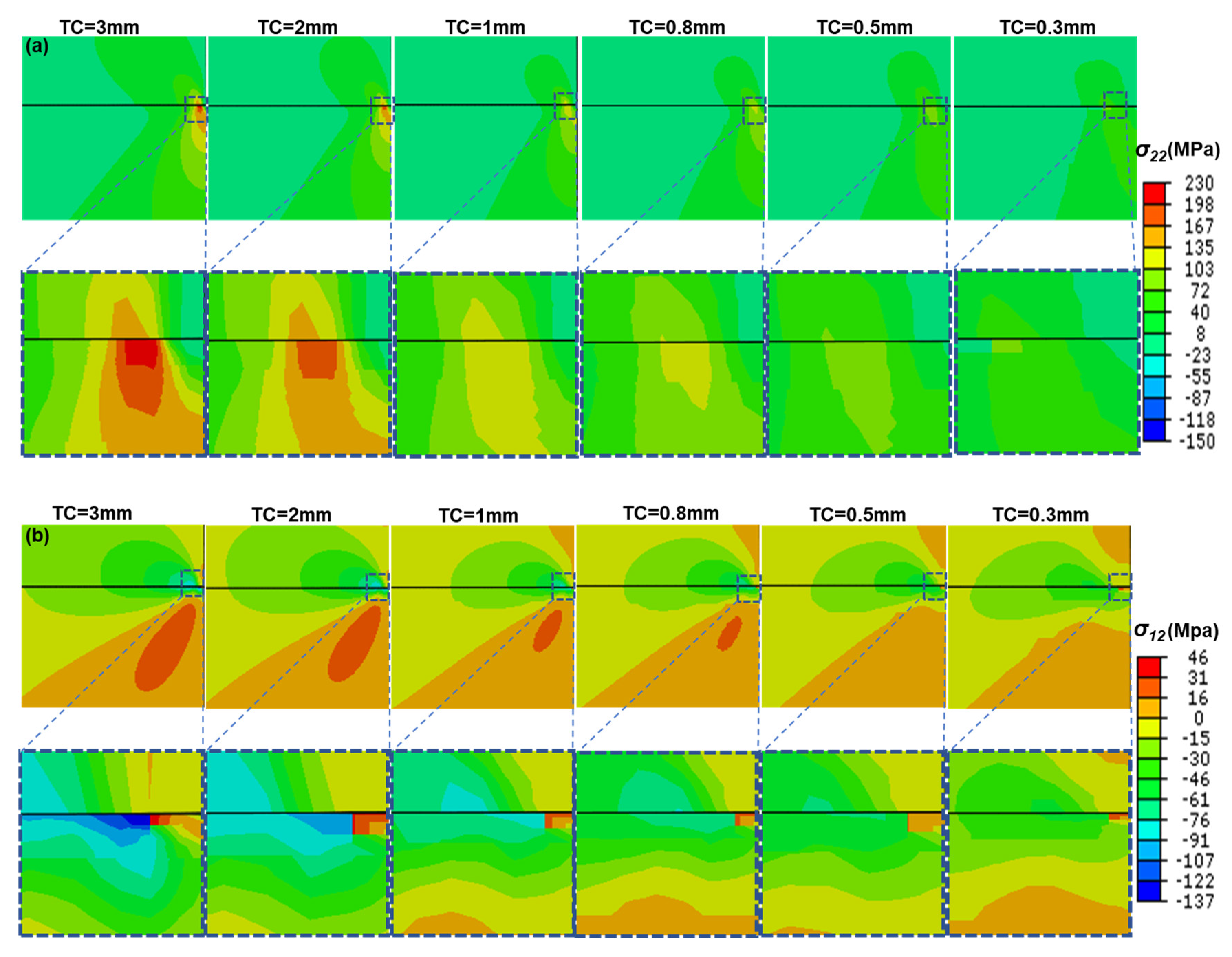
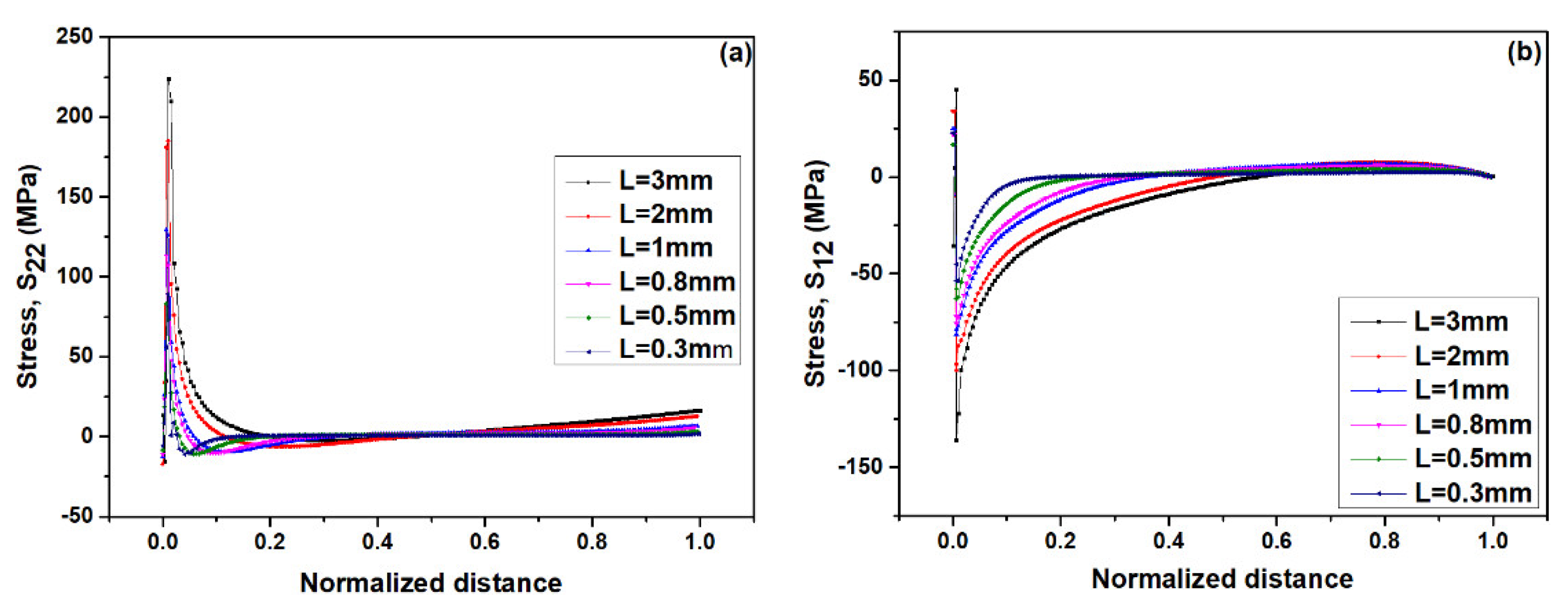
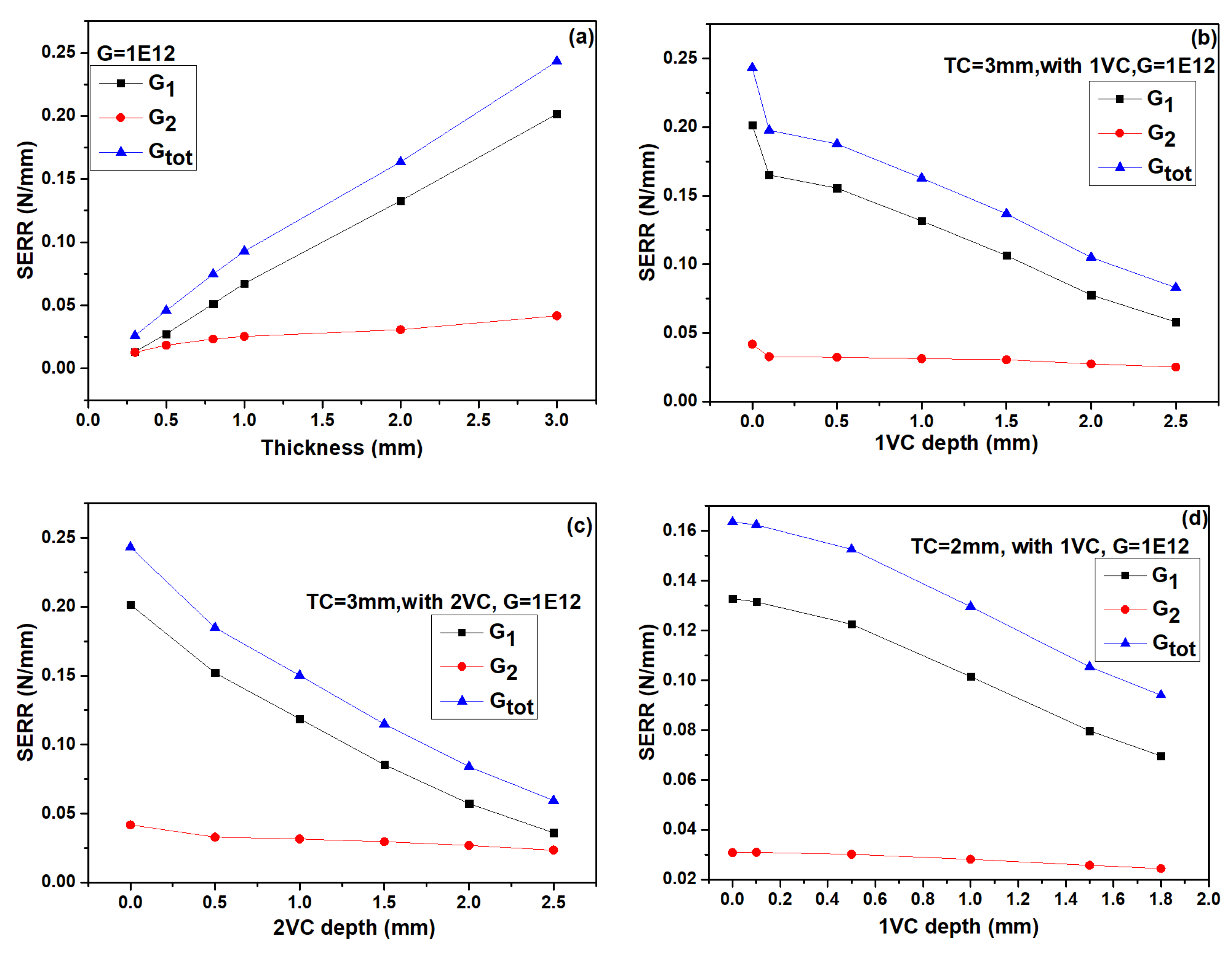
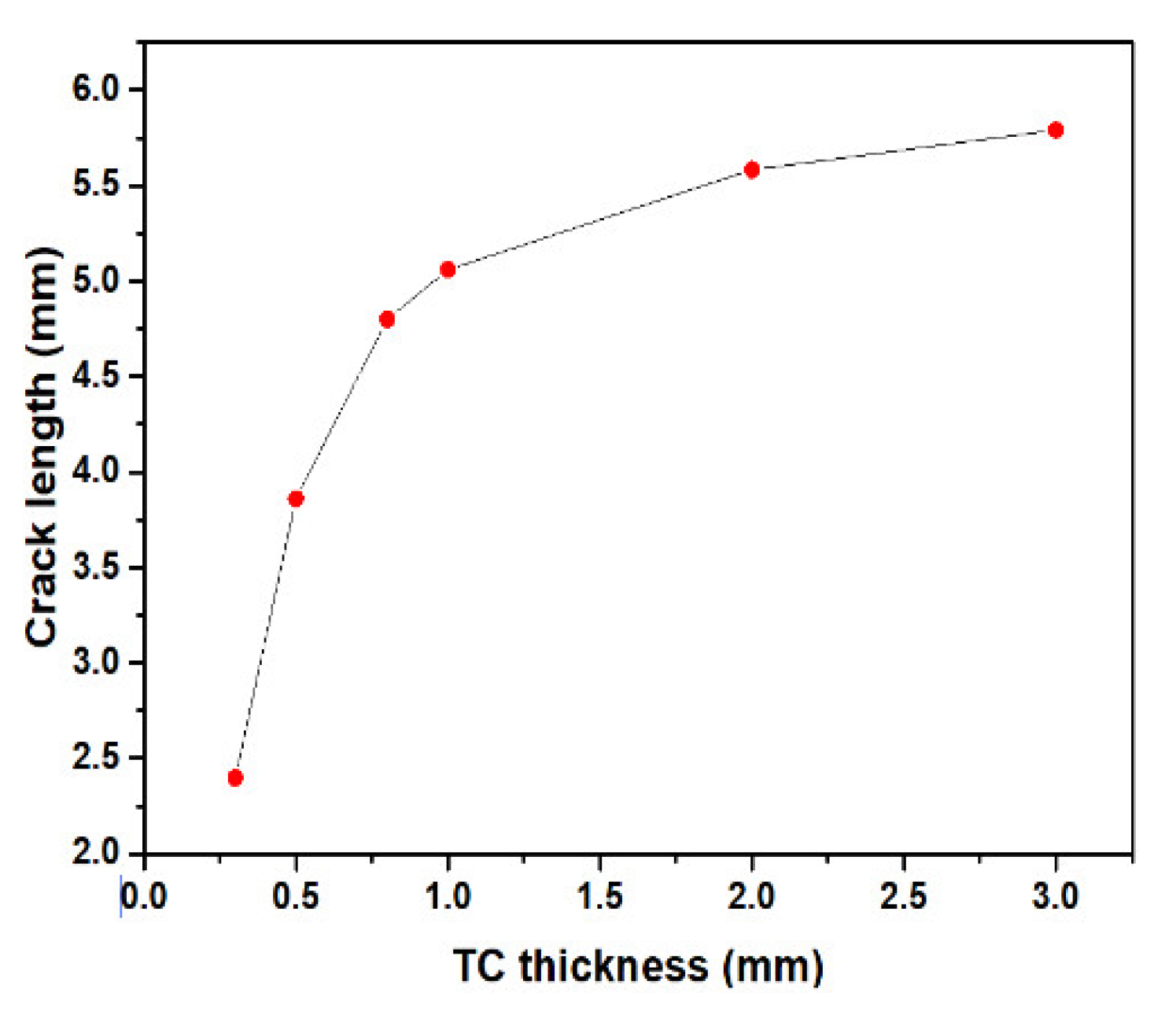
  • In top-coat (TC), the maximum stress are mainly concentrated at the tip of crack, which may lead to incipient crack nucleate and can cause the crack propagation in TC. Besides, these stresses (σ22 and σ12) and SERR increase continuously with the thickening of TC.
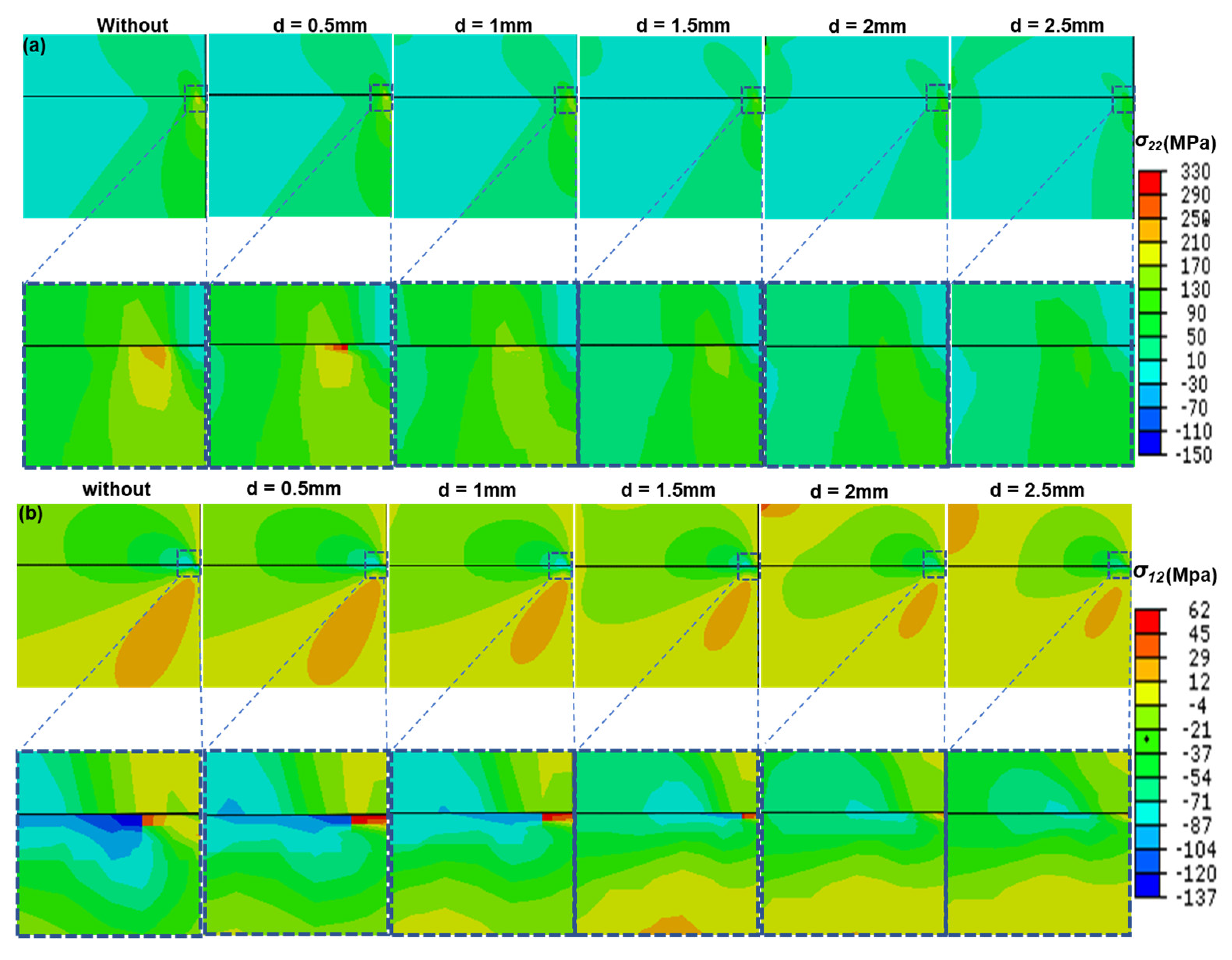
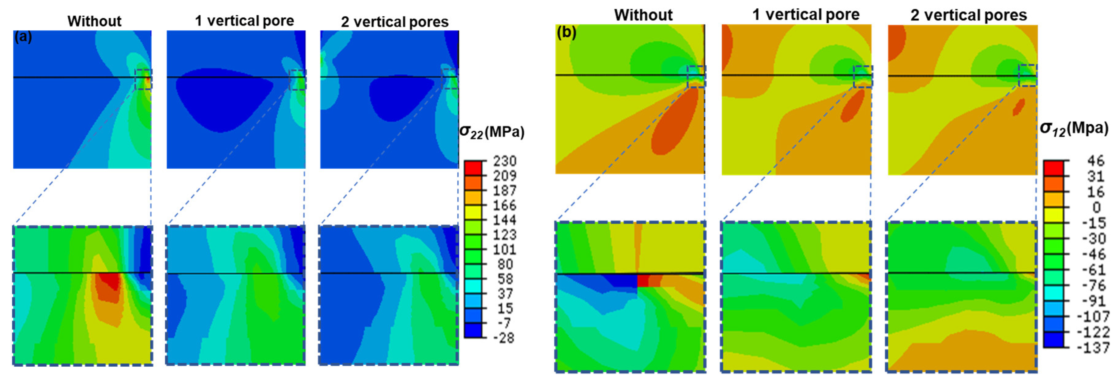
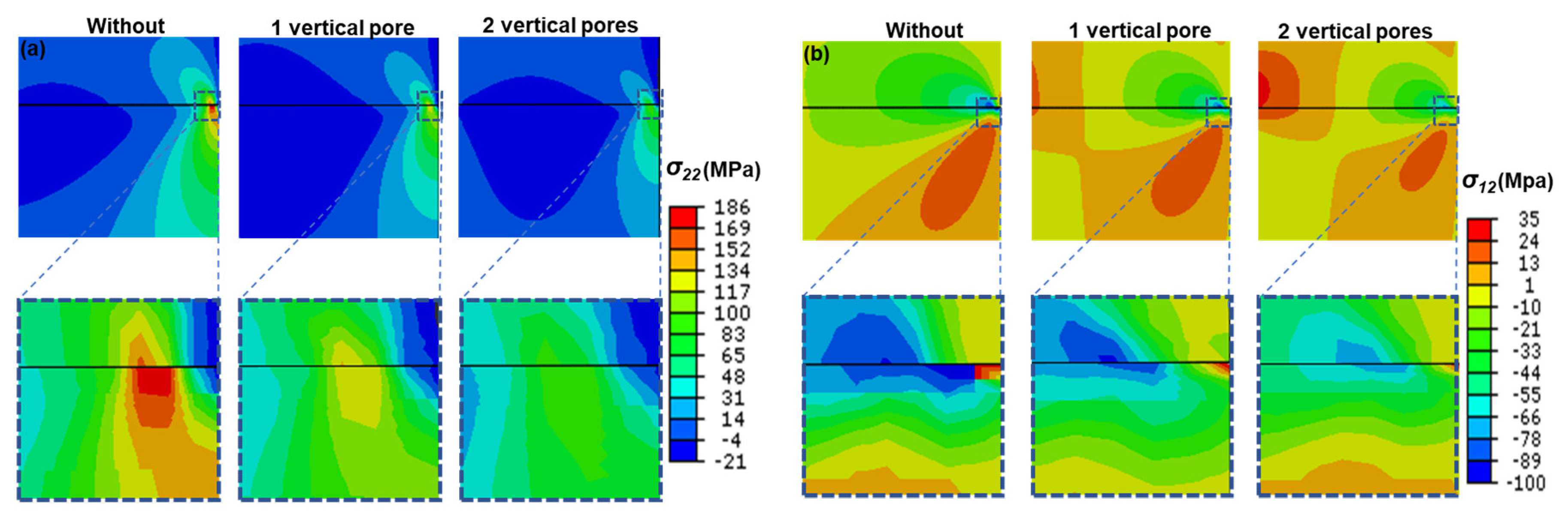
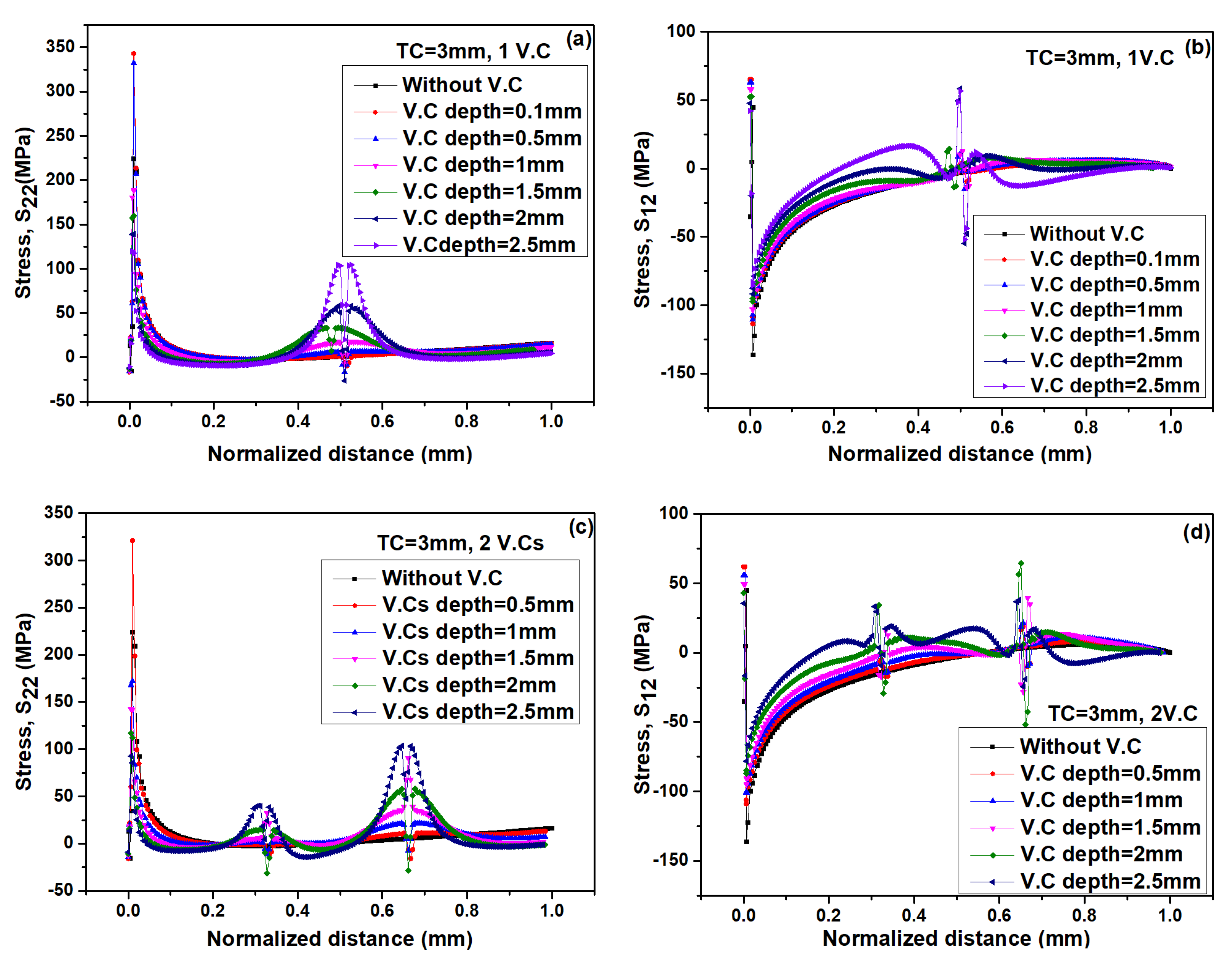
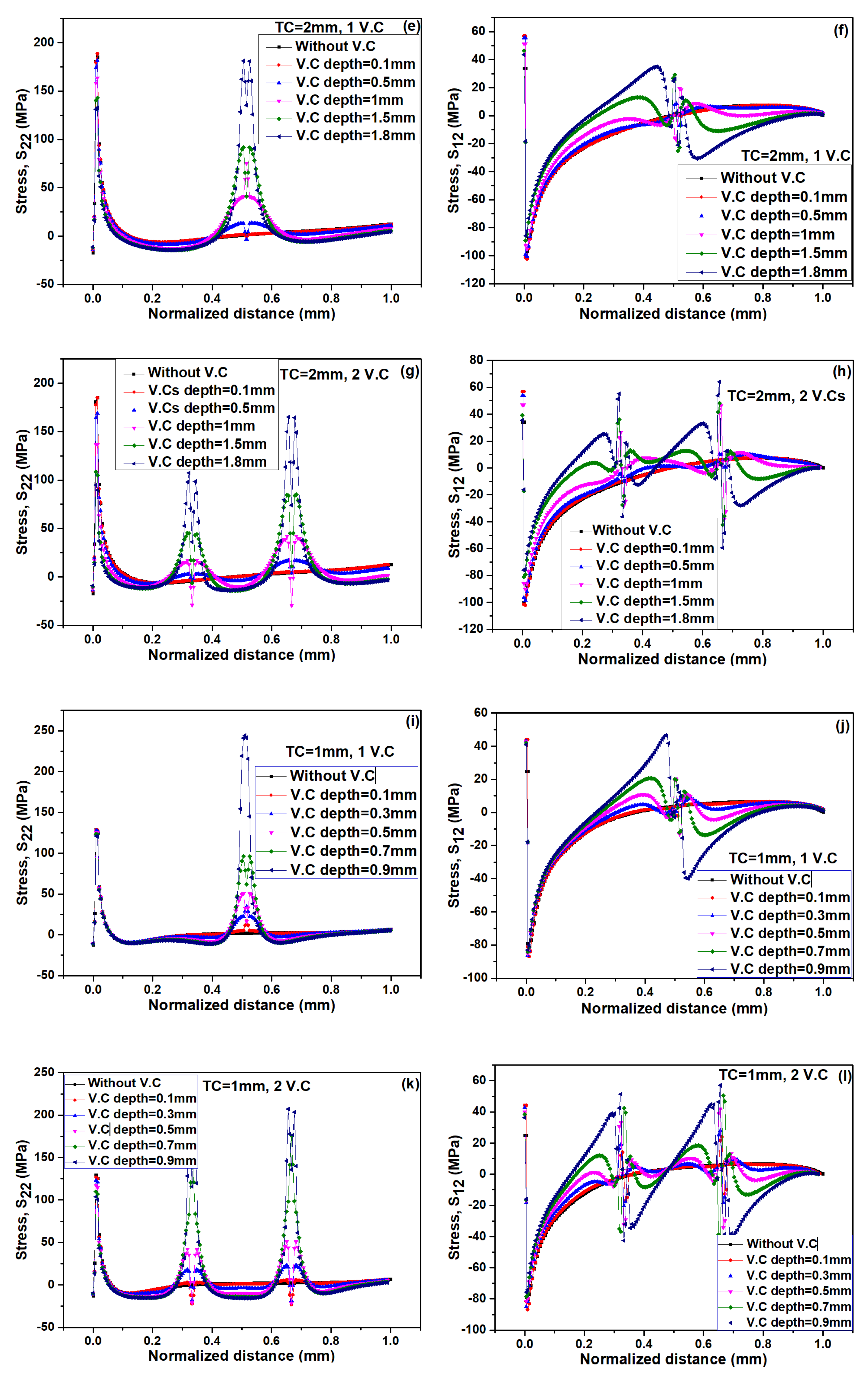
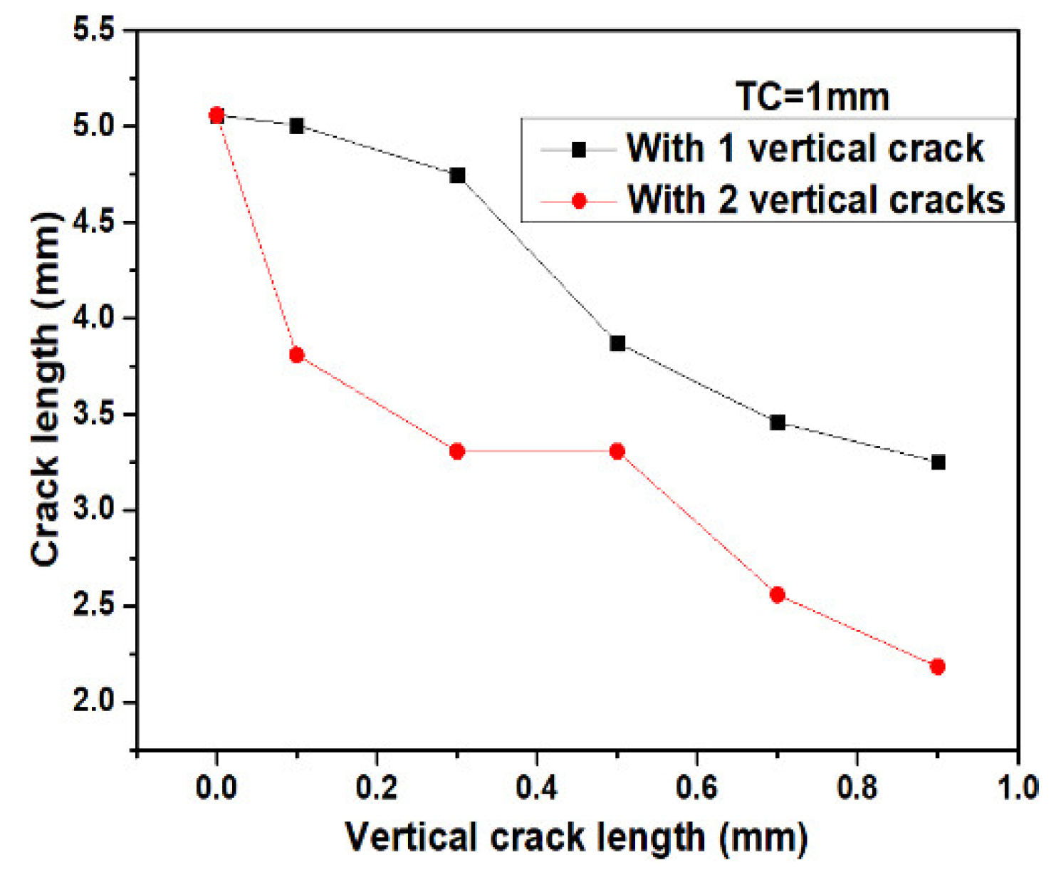
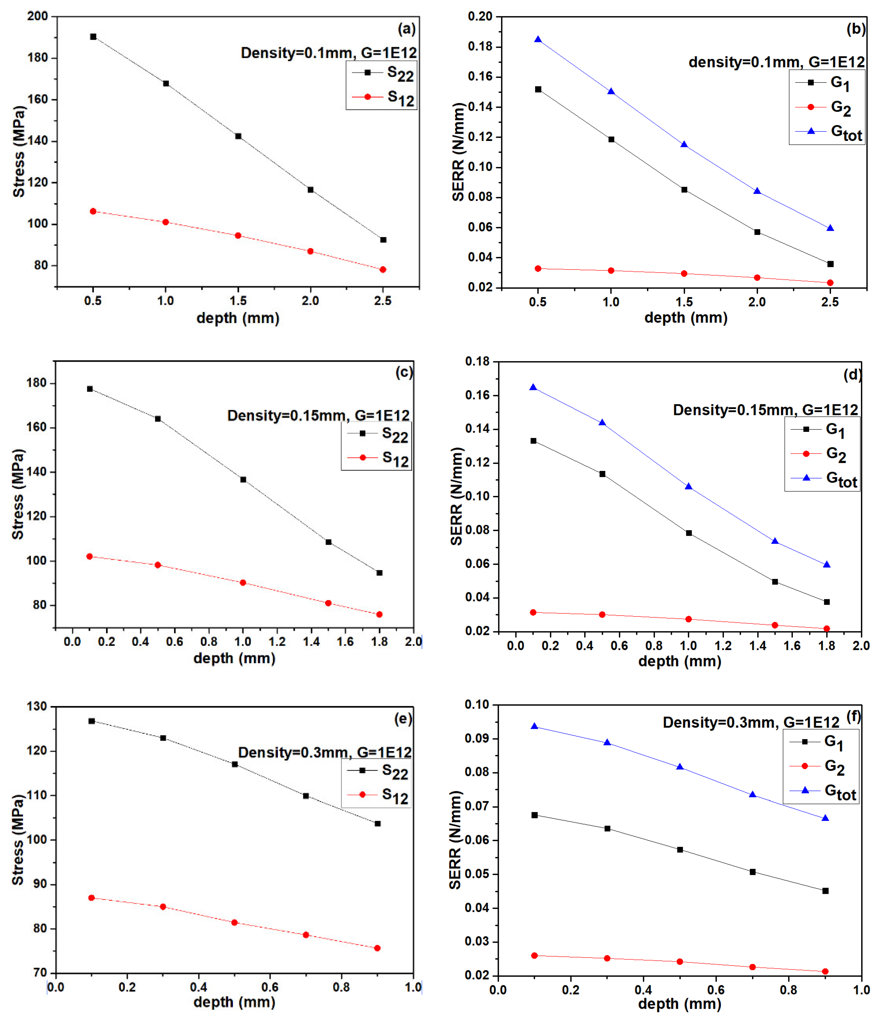
  • Vertical pores can enhance the strain tolerance of the TCs. The values of stresses (σ22 and σ12) decrease when one vertical pore is inserted in TC as compare to without vertical pore and further decreased for two vertical pores. Their values also decreased with an increase in the depth of vertical pores.
  • The values of SERRs for TBCs with vertical pores decrease compared to the TC without vertical pores. Their values also exhibit a decreasing trend with increasing the depth of vertical pores. These results indicate that the TCs with vertical pores exhibits excellent cracking resistance. This would contribute to extending the life span of thick coatings.

Author Contributions

Conceptualization, G.M. (Ghazanfar Mehboob); methodology, G.M. (Ghazanfar Mehboob); software, G.M. (Ghazanfar Mehboob) and A.T.; validation, G.-R.L.; formal analysis, G.M. (Ghazanfar Mehboob) and G.-R.L.; investigation, G.M. (Ghazanfar Mehboob); resources, G.-R.L.; data curation, G.-R.L. and T.X.; writing—original draft preparation, G.M. (Ghazanfar Mehboob); writing—review and editing, G.M. (Ghazanfar Mehboob), T.X., G.-R.L., S.H., G.M. (Gohar Mehboob) and A.T.; visualization, S.H. and G.M. (Gohar Mehboob ); supervision, G.-R.L.; project administration, G.-R.L.; funding acquisition, G.-R.L. All authors have read and agreed to the published version of the manuscript.

Funding

This research was funded by the National Natural Science Foundation of China (51801148); the China Postdoctoral Science Foundation (grant number 2019T120903, 2018M631151); the Opening Foundation from Science and Technology on Plasma Dynamics Laboratory in Air Force Engineering University of China (grant number 61422020701); the Postdoctoral Science Foundation of Shaanxi Province (grant number 2018BSHYDZZ59); the Natural Science Foundation of Shaanxi Province (grant number 2019JQ-165); the Young Talent fund of University Association for Science and Technology in Shaanxi, China (grant number 20190403).

Conflicts of Interest

The authors declare no conflict of interest.

References

  1. Carpenter, H.W. Radar Absorbing Coatings. U.S. Patent 6909395B1, 21 June 2005. [Google Scholar]
  2. Jie, Y.; Gang, X.; Mao-Sheng, C. A novel method of computation and optimization for multi-layered radar absorbing coatings using open source software. Mater. Des. 2006, 27, 45–52. [Google Scholar] [CrossRef]
  3. Shao, T.; Ma, H.; Wang, J.; Yan, M.; Feng, M.; Yang, Z.; Zhou, Q.; Wang, J.; Meng, Y.; Zhao, S.; et al. Ultra-thin and high temperature NiCrAlY alloy metamaterial enhanced radar absorbing coating. J. Alloy. Comp. 2020, 832, 154945. [Google Scholar] [CrossRef]
  4. Mehboob, G.; Liu, M.-J.; Xu, T.; Hussain, S.; Mehboob, G.; Tahir, A. A review on failure mechanism of thermal barrier coatings and strategies to extend their lifetime. Ceram. Int. 2020, 46, 8497–8521. [Google Scholar] [CrossRef]
  5. Selvadurai, U.; Hollingsworth, P.; Baumann, I.; Hussong, B.; Tillmann, W.; Rausch, S.; Biermann, D. Influence of the handling parameters on residual stresses of HVOF-sprayed WC-12Co coatings. Surf. Coat. Technol. 2015, 268, 30–35. [Google Scholar] [CrossRef]
  6. Feuerstein, A.; Knapp, J.; Taylor, T.; Ashary, A.; Bolcavage, A.; Hitchman, N. Technical and economical aspects of current thermal barrier coating systems for gas turbine engines by thermal spray and EBPVD: A review. J. Therm. Spray Technol. 2008, 17, 199–213. [Google Scholar] [CrossRef]
  7. Park, K.; Yang, B.; Kim, I.; Jang, K.; Myoung, S.; Park, C.; Scrivani, A. Effects of phase contents in feedstock powder and methods of thermal shock test on lifetime of thermal barrier coatings. Am. Soc. Mech. Eng. 2018, V006T24A001. [Google Scholar] [CrossRef]
  8. Cheng, B.; Yang, N.; Zhang, Q.; Zhang, Y.-M.; Chen, L.; Yang, G.-J.; Li, C.-X.; Li, C.-J. Sintering induced the failure behavior of dense vertically crack and lamellar structured TBCs with equivalent thermal insulation performance. Ceram. Int. 2017, 43, 15459–15465. [Google Scholar] [CrossRef]
  9. Li, G.-R.; Yang, G.-J.; Li, C.-X.; Li, C.-J. Strain-induced multiscale structural changes in lamellar thermal barrier coatings. Ceram. Int. 2017, 43, 2252–2266. [Google Scholar] [CrossRef]
  10. Li, G.; Yang, G.; Li, C.; Li, C. A comprehensive sintering mechanism for thermal barrier coatings-Part III: Substrate constraint effect on healing of 2D pores. J. Am. Ceram. Soc. 2018, 101, 3636–3648. [Google Scholar] [CrossRef]
  11. Bennett, T.D.; Yu, F. A nondestructive technique for determining thermal properties of thermal barrier coatings. J. Appl. Phys. 2005, 97, 013520. [Google Scholar] [CrossRef]
  12. Li, G.-R.; Wang, L.-S.; Yang, G.-J. Achieving self-enhanced thermal barrier performance through a novel hybrid-layered coating design. Mater. Des. 2019, 167, 107647. [Google Scholar] [CrossRef]
  13. Liu, Q.; Huang, S.; He, A. Composite ceramics thermal barrier coatings of yttria stabilized zirconia for aero-engines. J. Mater. Sci. Technol. 2019, 35, 2814–2823. [Google Scholar] [CrossRef]
  14. Zhao, H.; Levi, C.G.; Wadley, H.N.G. Molten silicate interactions with thermal barrier coatings. Surf. Coat. Technol. 2014, 251, 74–86. [Google Scholar] [CrossRef]
  15. Clarke, D.R.; Oechsner, M.; Padture, N.P. Thermal-barrier coatings for more efficient gas-turbine engines. MRS Bull. 2012, 37, 891–898. [Google Scholar] [CrossRef] [Green Version]
  16. Hille, T.S.; Nijdam, T.J.; Suiker, A.S.J.; Turteltaub, S.; Sloof, W.G. Damage growth triggered by interface irregularities in thermal barrier coatings. Acta Mater. 2009, 57, 2624–2630. [Google Scholar] [CrossRef]
  17. Darolia, R. Thermal barrier coatings technology: Critical review, progress update, remaining challenges and prospects. Int. Mater. Rev. 2013, 58, 315–348. [Google Scholar] [CrossRef]
  18. Padture, N.P.; Gell, M.; Jordan, E.H. Thermal barrier coatings for gas-turbine engine applications. Science 2002, 296, 280–284. [Google Scholar] [CrossRef] [PubMed]
  19. Meng, G.-H.; Zhang, B.-Y.; Liu, H.; Yang, G.-J.; Xu, T.; Li, C.-X.; Li, C.-J. Vacuum heat treatment mechanisms promoting the adhesion strength of thermally sprayed metallic coatings. Surf. Coat. Technol. 2018, 344, 102–110. [Google Scholar] [CrossRef]
  20. Meng, G.-H.; Zhang, B.-Y.; Liu, H.; Yang, G.-J.; Xu, T.; Li, C.-X.; Li, C.-J. Highly oxidation resistant and cost effective MCrAlY bond coats prepared by controlled atmosphere heat treatment. Surf. Coat. Technol. 2018, 347, 54–65. [Google Scholar] [CrossRef]
  21. Yang, L.; Liu, Q.X.; Zhou, Y.-C.; Mao, W.G.; Lu, C. Finite element simulation on thermal fatigue of a turbine blade with thermal barrier coatings. J. Mater. Sci. Technol. 2014, 30, 371–380. [Google Scholar] [CrossRef]
  22. Zhang, B.-Y.; Yang, G.-J.; Li, C.-X.; Li, C.-J. Non-parabolic isothermal oxidation kinetics of low pressure plasma sprayed MCrAlY bond coat. Appl. Surf. Sci. 2017, 406, 99–109. [Google Scholar] [CrossRef] [Green Version]
  23. Keyvani, A.; Bahamirian, M.; Kobayashi, A. Effect of sintering rate on the porous microstructural, mechanical and thermomechanical properties of YSZ and CSZ TBC coatings undergoing thermal cycling. J. Alloy. Compd. 2017, 727, 1057–1066. [Google Scholar] [CrossRef]
  24. Benini, E. Progress in Gas Turbine Performance; BoD—Books on Demand: Norderstedt, Germany, 2013. [Google Scholar]
  25. Bolelli, G.; Lusvarghi, L.; Pighetti, F.; Manfredini, T.; Mantini, F.P.; Polini, R.; Turunen, E.; Varis, T.; Hannula, S.-P. Comparison between plasma-and HVOF-sprayed ceramic coatings. Part I: Microstructure and mechanical properties. Int. J. Surf. Sci. Eng. 2007, 1, 38–61. [Google Scholar] [CrossRef]
  26. Shakhova, I.; Mironov, E.; Azarmi, F.; Safonov, A. Thermo-electrical properties of the alumina coatings deposited by different thermal spraying technologies. Ceram. Int. 2017, 43, 15392–15401. [Google Scholar] [CrossRef]
  27. Goberman, D.; Sohn, Y.H.; Shaw, L.; Jordan, E.; Gell, M. Microstructure development of Al2O3–13 wt.% TiO2 plasma sprayed coatings derived from nanocrystalline powders. Acta Mater. 2002, 50, 1141–1152. [Google Scholar] [CrossRef]
  28. Fan, W.; Bai, Y. Review of suspension and solution precursor plasma sprayed thermal barrier coatings. Ceram. Int. 2016, 42, 14299–14312. [Google Scholar]
  29. Li, G.-R.; Lv, B.-W.; Yang, G.-J.; Zhang, W.-X.; Li, C.-X.; Li, C.-J. Relationship between lamellar structure and elastic modulus of thermally sprayed thermal barrier coatings with intra-splat cracks. J. Therm. Spray Technol. 2015, 24, 1355–1367. [Google Scholar] [CrossRef]
  30. Xie, H.; Xie, Y.-C.; Yang, G.-J.; Li, C.-X.; Li, C.-J. Modeling thermal conductivity of thermally sprayed coatings with intrasplat cracks. J. Therm. Spray Technol. 2013, 22, 1328–1336. [Google Scholar] [CrossRef]
  31. Zhang, W.-W.; Li, G.-R.; Zhang, Q.; Yang, G.-J.; Zhang, G.-W.; Mu, H.-M. Self-enhancing thermal insulation performance of bimodal-structured thermal barrier coating. J. Therm. Spray Technol. 2018, 27, 1064–1075. [Google Scholar] [CrossRef]
  32. Wang, X.; Guo, L.; Guo, H.; Ma, G.; Gong, S. Effects of pressure during preparation on the grain orientation of ruddlesden—popper structured BaLa2Ti3O10 ceramic. J. Mater. Sci. Technol. 2014, 30, 455–458. [Google Scholar] [CrossRef]
  33. Chen, L.; Yang, G.-J. Epitaxial growth and cracking of highly tough 7YSZ splats by thermal spray technology. J. Adv. Ceram. 2018, 7, 17–29. [Google Scholar] [CrossRef] [Green Version]
  34. Li, G.-R.; Wang, L.-S.; Yang, G.-J. A novel composite-layered coating enabling self-enhancing thermal barrier performance. Scr. Mater. 2019, 163, 142–147. [Google Scholar] [CrossRef]
  35. Wei, Z.-Y.; Cai, H.-N.; Li, C.-J. Comprehensive dynamic failure mechanism of thermal barrier coatings based on a novel crack propagation and TGO growth coupling model. Ceram. Int. 2018, 44, 22556–22566. [Google Scholar] [CrossRef]
  36. Zhang, W.-W.; Li, G.-R.; Zhang, Q.; Yang, G.-J.; Zhang, G.-W.; Mu, H.-M. Bimodal TBCs with low thermal conductivity deposited by a powder-suspension co-spray process. J. Mater. Sci. Technol. 2018, 34, 1293–1304. [Google Scholar] [CrossRef]
  37. Li, G.-R.; Yang, G.-J.; Chen, X.-F.; Li, C.-X.; Li, C.-J. Strain/sintering co-induced multiscale structural changes in plasma-sprayed thermal barrier coatings. Ceram. Int. 2018, 44, 14408–14416. [Google Scholar] [CrossRef]
  38. Chen, Q.-Y.; Peng, X.-Z.; Yang, G.-J.; Li, C.-X.; Li, C.-J. Characterization of plasma jet in plasma spray-physical vapor deposition of YSZ using a <80 kW shrouded torch based on optical emission spectroscopy. J. Therm. Spray Technol. 2015, 24, 1038–1045. [Google Scholar] [CrossRef]
  39. Liu, M.-J.; Zhang, K.-J.; Zhang, Q.; Zhang, M.; Yang, G.-J.; Li, C.-X.; Li, C.-J. Thermodynamic conditions for cluster formation in supersaturated boundary layer during plasma spray-physical vapor deposition. Appl. Surf. Sci. 2019, 471, 950–959. [Google Scholar] [CrossRef]
  40. Wang, L.; Liu, C.G.; Zhong, X.H.; Zhao, Y.X.; Zhao, H.Y.; Yang, J.S.; Tao, S.Y.; Wang, Y. Investigation of crack propagation behavior of atmospheric plasma-sprayed thermal barrier coatings under uniaxial tension using the acoustic emission technique. J. Therm. Spray Technol. 2015, 24, 296–308. [Google Scholar] [CrossRef]
  41. Evans, A.G.; Mumm, D.R.; Hutchinson, J.W.; Meier, G.H.; Pettit, F.S. Mechanisms controlling the durability of thermal barrier coatings. Prog. Mater. Sci. 2001, 46, 505–553. [Google Scholar] [CrossRef]
  42. Schulz, U.; Leyens, C.; Fritscher, K.; Peters, M.; Saruhan-Brings, B.; Lavigne, O.; Dorvaux, J.-M.; Poulain, M.; Mévrel, R.; Caliez, M. Some recent trends in research and technology of advanced thermal barrier coatings. Aerosp. Sci. Technol. 2003, 7, 73–80. [Google Scholar] [CrossRef]
  43. Zhang, X.; Zhou, K.; Xu, W.; Song, J.; Deng, C.; Liu, M. Reaction mechanism and thermal insulation property of al-deposited 7YSZ thermal barrier coating. J. Mater. Sci. Technol. 2015, 31, 1006–1010. [Google Scholar] [CrossRef]
  44. Zhang, W.-W.; Li, G.-R.; Zhang, Q.; Yang, G.-J. Multiscale pores in TBCs for lower thermal conductivity. J. Therm. Spray Technol. 2017, 26, 1183–1197. [Google Scholar] [CrossRef]
  45. Li, C.-J.; Ohmori, A. Relationships between the microstructure and properties of thermally sprayed deposits. J. Therm. Spray Technol. 2002, 11, 365–374. [Google Scholar] [CrossRef]
  46. Li, C.; Ohmori, A.; McPherson, R. The relationship between microstructure and Young’s modulus of thermally sprayed ceramic coatings. J. Mater. Sci. 1997, 32, 997–1004. [Google Scholar] [CrossRef]
  47. Li, G.-R.; Yang, G.-J.; Li, C.-X.; Li, C.-J. Stage-sensitive microstructural evolution of nanostructured TBCs during thermal exposure. J. Eur. Ceram. Soc. 2018, 38, 3325–3332. [Google Scholar] [CrossRef]
  48. Li, C.-J.; Li, Y.; Yang, G.-J.; Li, C.-X. A novel plasma-sprayed durable thermal barrier coating with a well-bonded YSZ interlayer between porous YSZ and bond coat. J. Therm. Spray Technol. 2012, 21, 383–390. [Google Scholar] [CrossRef]
  49. Chen, L.; Yang, G. Epitaxial growth and cracking mechanisms of thermally sprayed ceramic splats. J. Therm. Spray Technol. 2018, 27, 255–268. [Google Scholar] [CrossRef]
  50. Chen, L.; Yang, G.-J.; Li, C.-X. Formation of lamellar pores for splats via interfacial or sub-interfacial delamination at chemically bonded region. J. Therm. Spray Technol. 2017, 26, 315–326. [Google Scholar] [CrossRef]
  51. Li, G.; Yang, G. Understanding of degradation-resistant behavior of nanostructured thermal barrier coatings with bimodal structure. J. Mater. Sci. Technol. 2019, 35, 231–238. [Google Scholar] [CrossRef]
  52. Li, C.-J.; Dong, H.; Ding, H.; Yang, G.-J.; Li, C.-X. The correlation of the TBC lifetimes in burner cycling test with thermal gradient and furnace isothermal cycling test by TGO effects. J. Therm. Spray Technol. 2017, 26, 378–387. [Google Scholar] [CrossRef]
  53. Li, G.-R.; Wang, L.-S. Durable TBCs with self-enhanced thermal insulation based on co-design on macro-and microstructure. Appl. Surf. Sci. 2019, 483, 472–480. [Google Scholar] [CrossRef]
  54. Jonnalagadda, K.P.; Eriksson, R.; Yuan, K.; Li, X.-H.; Ji, X.; Yu, Y.; Peng, R.L. Comparison of damage evolution during thermal cycling in a high purity nano and a conventional thermal barrier coating. Surf. Coat. Technol. 2017, 332, 47–56. [Google Scholar] [CrossRef]
  55. Rad, M.R.; Farrahi, G.H.; Azadi, M.; Ghodrati, M. Effects of preheating temperature and cooling rate on two-step residual stress in thermal barrier coatings considering real roughness and porosity effect. Ceram. Int. 2014, 40, 15925–15940. [Google Scholar] [CrossRef]
  56. Jonnalagadda, K.P.; Eriksson, R.; Yuan, K.; Li, X.-H.; Ji, X.; Yu, Y.; Peng, R.L. A study of damage evolution in high purity nano TBCs during thermal cycling: A fracture mechanics based modeling approach. J. Eur. Ceram. Soc. 2017, 37, 2889–2899. [Google Scholar] [CrossRef]
  57. Li, Y.; Li, C.-J.; Yang, G.-J.; Xing, L.-K. Thermal fatigue behavior of thermal barrier coatings with the MCrAlY bond coats by cold spraying and low-pressure plasma spraying. Surf. Coat. Technol. 2010, 205, 2225–2233. [Google Scholar] [CrossRef]
  58. Bobzin, K.; Brögelmann, T.; Brugnara, R.H.; Arghavani, M.; Yang, T.-S.; Chang, Y.-Y.; Chang, S.-Y. Investigation on plastic behavior of HPPMS CrN, AlN and CrN/AlN-multilayer coatings using finite element simulation and nanoindentation. Surf. Coat. Technol. 2015, 284, 310–317. [Google Scholar] [CrossRef]
  59. Abdul-Baqi, A.; van der Giessen, E. Indentation-induced interface delamination of a strong film on a ductile substrate. Thin Solid Film. 2001, 381, 143–154. [Google Scholar] [CrossRef] [Green Version]
  60. Rezaei, S.; Wulfinghoff, S.; Reese, S. Prediction of fracture and damage in micro/nano coating systems using cohesive zone elements. Int. J. Solids Struct. 2017, 121, 62–74. [Google Scholar] [CrossRef]
  61. Holmberg, K.; Laukkanen, A.; Ronkainen, H.; Wallin, K. Finite element analysis of coating adhesion failure in pre-existing crack field. Tribol. Mater. Surf. Interface 2013, 7, 42–51. [Google Scholar] [CrossRef]
  62. Wang, L.; Li, D.C.; Yang, J.S.; Shao, F.; Zhong, X.H.; Zhao, H.Y.; Yang, K.; Tao, S.Y.; Wang, Y. Modeling of thermal properties and failure of thermal barrier coatings with the use of finite element methods: A review. J. Eur. Ceram. Soc. 2016, 36, 1313–1331. [Google Scholar] [CrossRef]
  63. SIMULA Corp. Manaul, abaqus analysisi users. In Abaqus Documentation Version 6.14-1, Dassault Systems; SIMULA Corp: Providence, RI, USA, 2014. [Google Scholar]
  64. Rybicki, E.F.; Kanninen, M.F. A finite element calculation of stress intensity factors by a modified crack closure integral. Eng. Fract. Mech. 1977, 9, 931–938. [Google Scholar] [CrossRef]
  65. Fan, X.L.; Xu, R.; Zhang, W.X.; Wang, T.J. Effect of periodic surface cracks on the interfacial fracture of thermal barrier coating system. Appl. Surf. Sci. 2012, 258, 9816–9823. [Google Scholar] [CrossRef]
  66. Wei, Z.-Y.; Cai, H.-N.; Feng, R.-X.; Su, J.-Y. Dynamic crack growth mechanism and lifetime assessment in plasma sprayed thermal barrier system upon temperature cycling. Ceram. Int. 2019, 45, 14896–14907. [Google Scholar] [CrossRef]
  67. Rabiei, A.; Evans, A.G. Failure mechanisms associated with the thermally grown oxide in plasma-sprayed thermal barrier coatings. Acta Mater. 2000, 48, 3963–3976. [Google Scholar] [CrossRef]
  68. Wang, L.; Yang, J.S.; Ni, J.X.; Liu, C.G.; Zhong, X.H.; Shao, F.; Zhao, H.Y.; Tao, S.Y.; Wang, Y. Influence of cracks in APS-TBCs on stress around TGO during thermal cycling: A numerical simulation study. Surf. Coat. Technol. 2016, 285, 98–112. [Google Scholar] [CrossRef]
  69. Wang, L.; Zhong, X.H.; Shao, F.; Ni, J.X.; Yang, J.S.; Tao, S.Y.; Wang, Y. What is the suitable segmentation crack density for atmospheric plasma sprayed thick thermal barrier coatings with the improved thermal shock resistance? Appl. Surf. Sci. 2018, 431, 101–111. [Google Scholar] [CrossRef]
  70. Zhu, W.; Zhang, Z.B.; Yang, L.; Zhou, Y.C.; Wei, Y.G. Spallation of thermal barrier coatings with real thermally grown oxide morphology under thermal stress. Mater. Des. 2018, 146, 180–193. [Google Scholar] [CrossRef]
  71. Zhu, W.; Zhang, Z.B.; Yang, L.; Zhou, Y.C.; Wei, Y.G. Determination of interfacial adhesion energies of thermal barrier coatings by compression test combined with a cohesive zone finite element model. Int. J. Plast. 2015, 64, 76–87. [Google Scholar] [CrossRef]
  72. Aktaa, J.; Sfar, K.; Munz, D. Assessment of TBC systems failure mechanisms using a fracture mechanics approach. Acta Mater. 2005, 53, 4399–4413. [Google Scholar] [CrossRef]
  73. Zhao, P.F.; Sun, C.A.; Zhu, X.Y.; Shang, F.L.; Li, C.J. Fracture toughness measurements of plasma-sprayed thermal barrier coatings using a modified four-point bending method. Surf. Coat. Technol. 2010, 204, 4066–4074. [Google Scholar] [CrossRef]
  74. Gibson, J.S.-L.; Rezaei, S.; Rueß, H.; Hans, M.; Music, D.; Wulfinghoff, S.; Schneider, J.M.; Reese, S.; Korte-Kerzel, S. From quantum to continuum mechanics: Studying the fracture toughness of transition metal nitrides and oxynitrides. Mater. Res. Lett. 2018, 6, 142–151. [Google Scholar] [CrossRef] [Green Version]
  75. Rezaei, S.; Arghavani, M.; Wulfinghoff, S.; Kruppe, N.C.; Brögelmann, T.; Reese, S.; Bobzin, K. A novel approach for the prediction of deformation and fracture in hard coatings: Comparison of numerical modeling and nanoindentation tests. Mech. Mater. 2018, 117, 192–201. [Google Scholar] [CrossRef]
  76. Song, X.; Zhang, J.; Lin, C.; Liu, Z.; Jiang, C.; Kong, M.; Zeng, Y. Microstructures and residual strain/stresses of YSZ coatings prepared by plasma spraying. Mater. Lett. 2019, 240, 217–220. [Google Scholar] [CrossRef]
  77. Mahalingam, S.; Yunus, S.M.; Manap, A.; Afandi, N.M.; Zainuddin, R.A.; Kadir, N.F. crack propagation and effect of mixed oxides on TGO growth in thick La–Gd–YSZ thermal barrier coating. Coatings 2019, 9, 719. [Google Scholar] [CrossRef] [Green Version]
  78. Lu, S.; Huang, J.; Song, L.; Yi, M. A study on zoning coating method of absorbing materials for stealth aircraft. Optik 2020, 208, 163912. [Google Scholar] [CrossRef]
  79. Madhwal, M.; Jordan, E.H.; Gell, M. Failure mechanisms of dense vertically-cracked thermal barrier coatings. Mater. Sci. Eng. A 2004, 384, 151–161. [Google Scholar] [CrossRef]
Figure 1. Model of TBCs with the TC crack close to the interface: (a) the physical geometry model; (b) FE mesh and boundary conditions; and (c) the refined meshes near the TC/BC interface.
Coatings 10 01066 g001
Figure 2. Schematic diagram of the virtual crack closure technique (VCCT) used for the simulation of crack growth in the TC layer.
Coatings 10 01066 g002
Figure 3. Variation of stress field: (a) σ22 and (b) σ12 at crack tip with different TC thickness.
Coatings 10 01066 g003
Figure 4. Variation of stress field: (a) σ22 and (b) σ12 at crack tip for different depths of 3 mm thickness of TC with one vertical crack.
Coatings 10 01066 g004
Figure 5. Variation of stress field: (a) σ22 and (b) σ12 at crack tip for different depths of 3 mm thickness of TC with two vertical cracks.
Coatings 10 01066 g005
Figure 6. Variation of stress field: (a) σ22 and (b) σ12 at crack tip for 3 mm thickness of TC without, with one vertical pore, and with two vertical pores. The depth of vertical pores was 2.5 mm.
Coatings 10 01066 g006
Figure 7. Variation of stress field: (a) σ22 and (b) σ12 at crack tip for 2 mm thickness of TC without, with one vertical pore, and with two vertical pores. The depth of vertical pores was 1.8 mm.
Coatings 10 01066 g007
Figure 8. Variation of stress field: (a) σ22 and (b) σ12 at crack tip for 1 mm thickness of TC without, with one vertical pore, and with two vertical pores. The depth of vertical pores was 0.9 mm.
Coatings 10 01066 g008
Figure 9. Variation of stresses (a) σ22 and (b) σ12 along crack path at different thickness of TC.
Coatings 10 01066 g009
Figure 10. Stress distribution along crack line, with one and two vertical cracks in 3 mm thickness of TC (ad), with one and two vertical cracks in 2 mm thickness of TC (eh), with one and two vertical cracks in 1 mm thickness of TC (il).
Coatings 10 01066 g010aCoatings 10 01066 g010b
Figure 11. SERR11, SERR12, and SERRtotal at crack tip affected by, thickness of TC (a) and depth of vertical pores at different thicknesses of TC (bg).
Coatings 10 01066 g011aCoatings 10 01066 g011b
Figure 12. Plot of crack length as a function of thickness of ceramic coating.
Coatings 10 01066 g012
Figure 13. Plot of crack length as a function of depth of vertical pores for one vertical pore and two vertical pores.
Coatings 10 01066 g013
Figure 14. Effect of crack density and crack depth on stress and SERR: stresses at density (a) 0.1 mm, (c) 0.15 mm, (e) 0.3 mm and SERR at density (b) 0.1 mm, (d) 0.15 mm, (f) 0.3 mm.
Coatings 10 01066 g014
Table 1. Material properties (Young’s modulus E, Poisson ratio ν, and Thermal expansion coefficient α) of SUB, BC, and TC [65,66,67,68,70].
LayersE (GPa)να (10−6/K)
SUB2100.39
BC2000.313.6
TC500.1514.8
Publisher’s Note: MDPI stays neutral with regard to jurisdictional claims in published maps and institutional affiliations.

