Immunosensing Based on Optical Fiber Technology: Recent Advances

 , ,
, ,  , , , and
Abstract
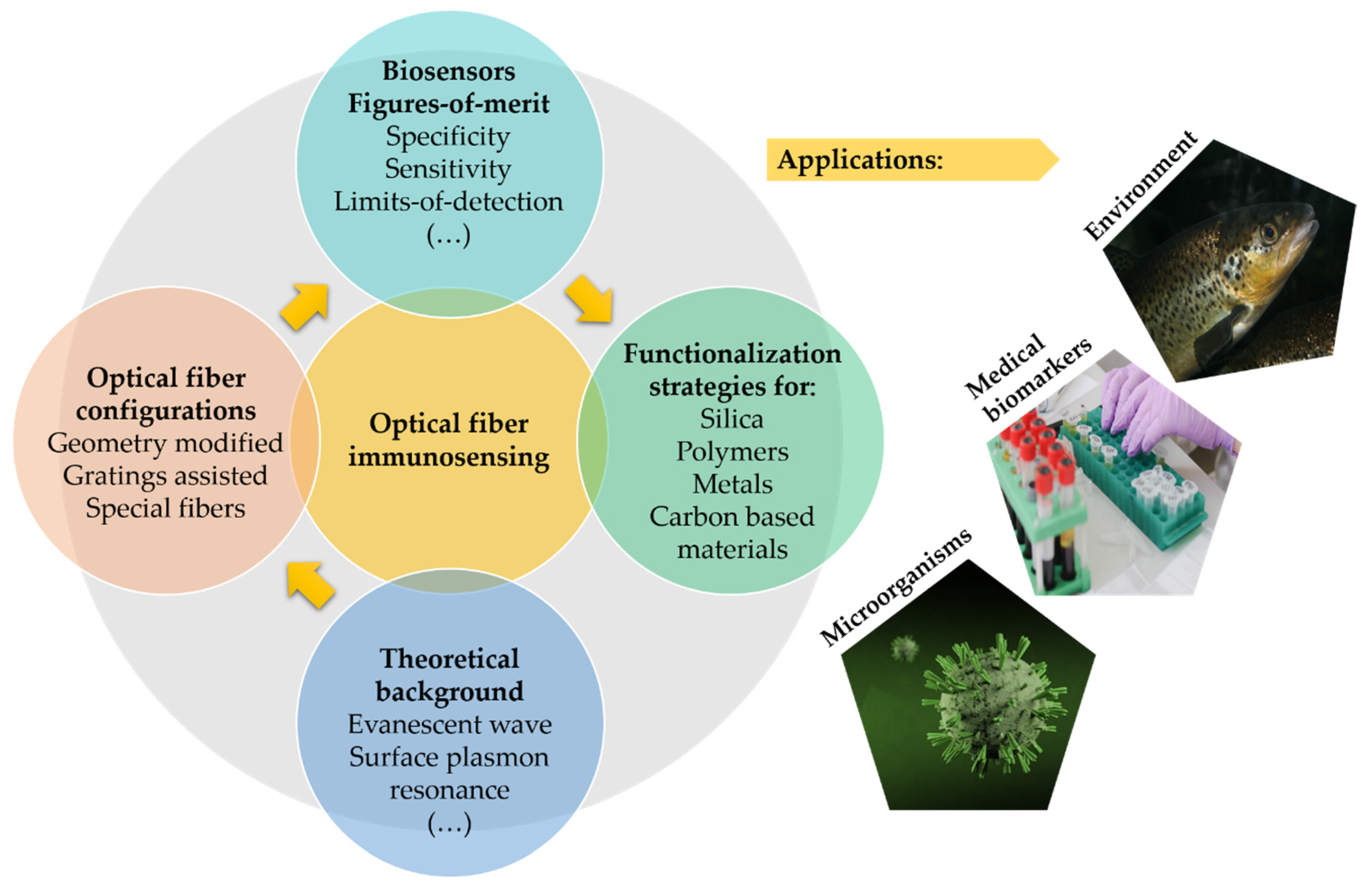
:1. Introduction
2. Theoretical Background on Optical Fiber Biosensing Working Principles
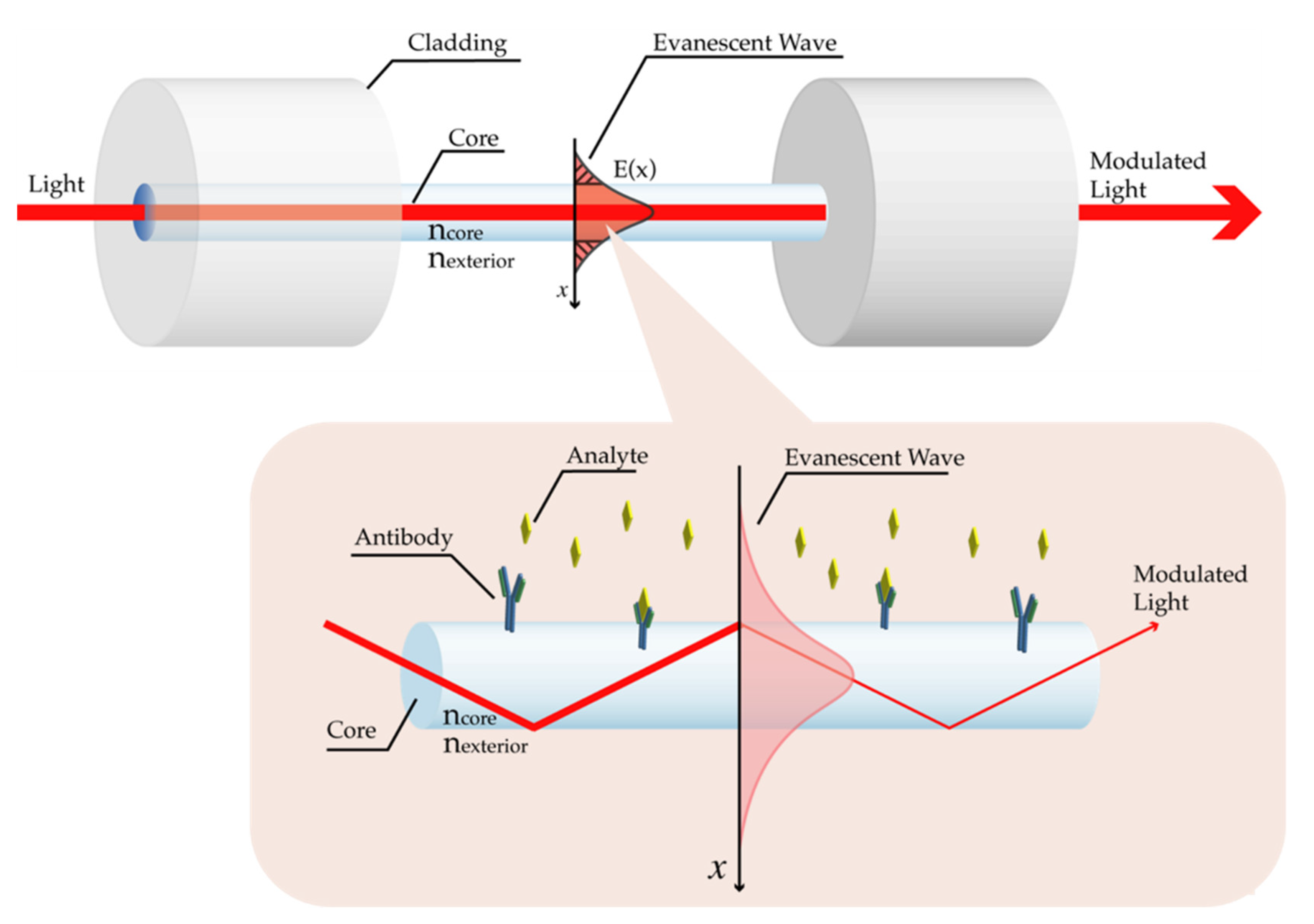
2.1. Evanescent Wave
2.2. Surface Plasmon Resonance and Localized Surface Plasmon Resonance
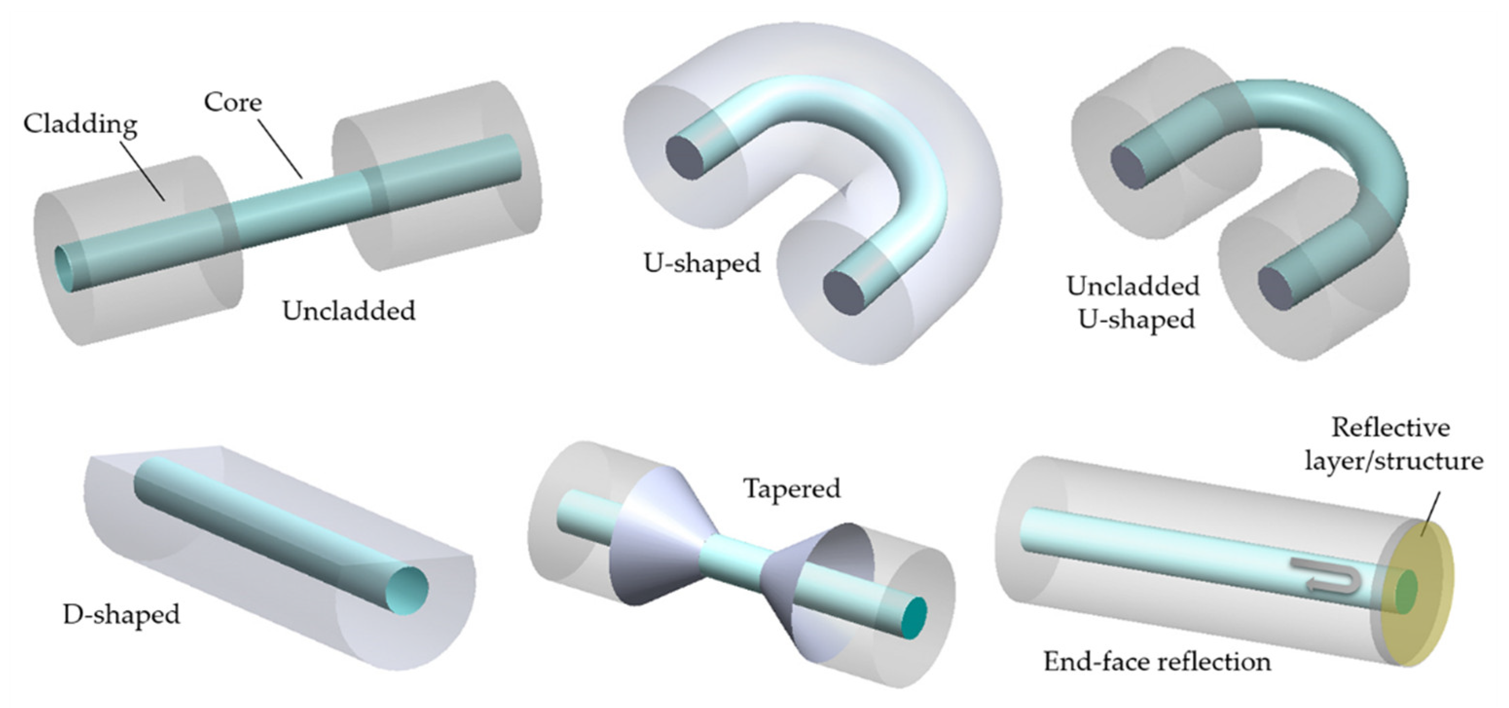
2.3. Optical Fiber Configurations for Biosensing
2.3.1. Geometry-Modified
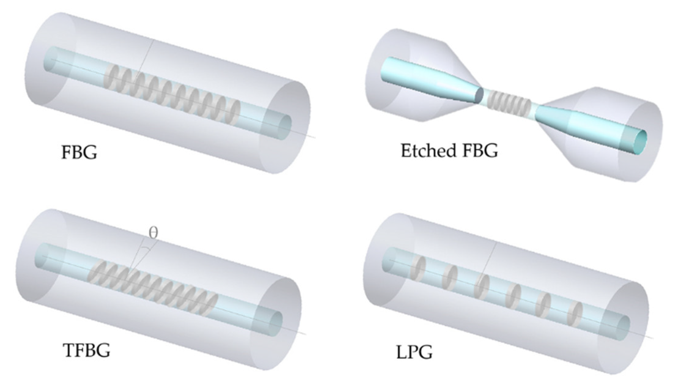
2.3.2. Grating-Based
2.3.3. Special Fibers
2.4. Figures-of-Merit of Biosensors
3. Biofunctionalization Strategies for Optical Fiber Immunosensors
3.1. Bare Silica Optical Fiber
3.2. Plastic Optical Fiber
3.3. Metal-Coated Fibers
3.4. Carbon-Based Material Coated Fibers
3.5. Semiconductor Material Coated Fibers
4. Biosensing Applications
4.1. Microorganism Detection
4.1.1. Bacteria
4.1.2. Virus
4.2. Medical Biomarkers Detection
4.2.1. Cancer Biomarkers
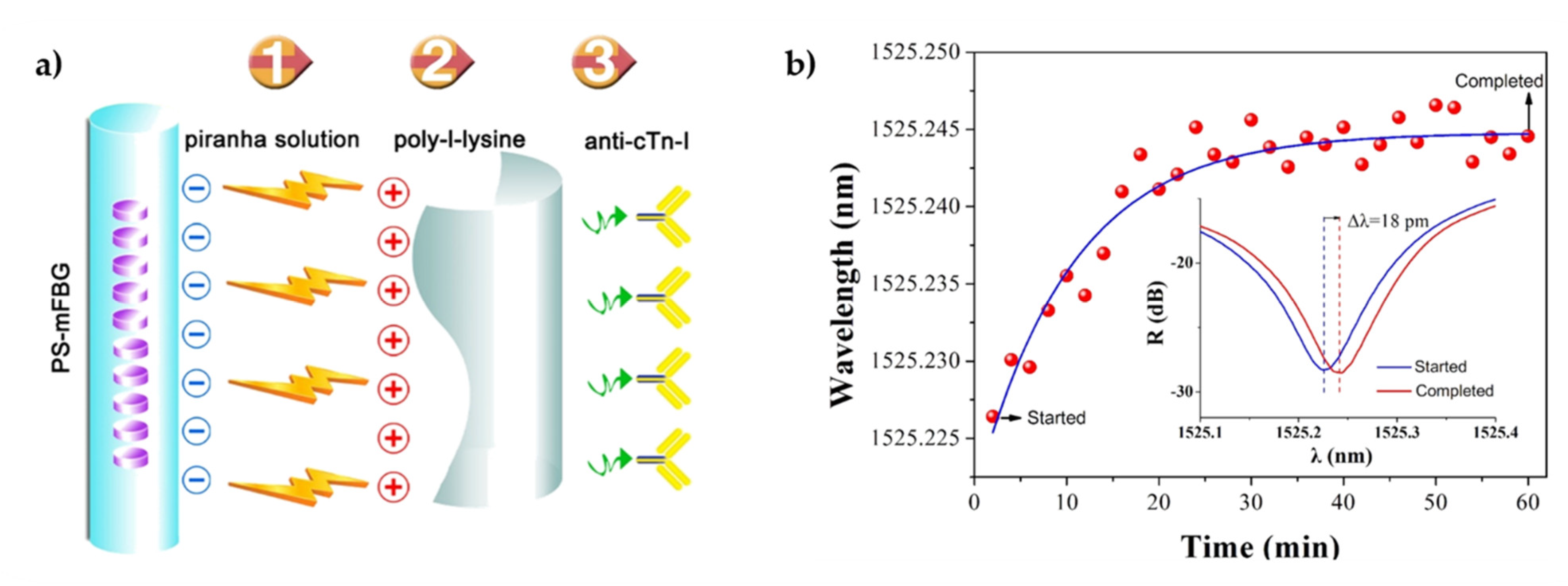
4.2.2. Cardiac Biomarkers
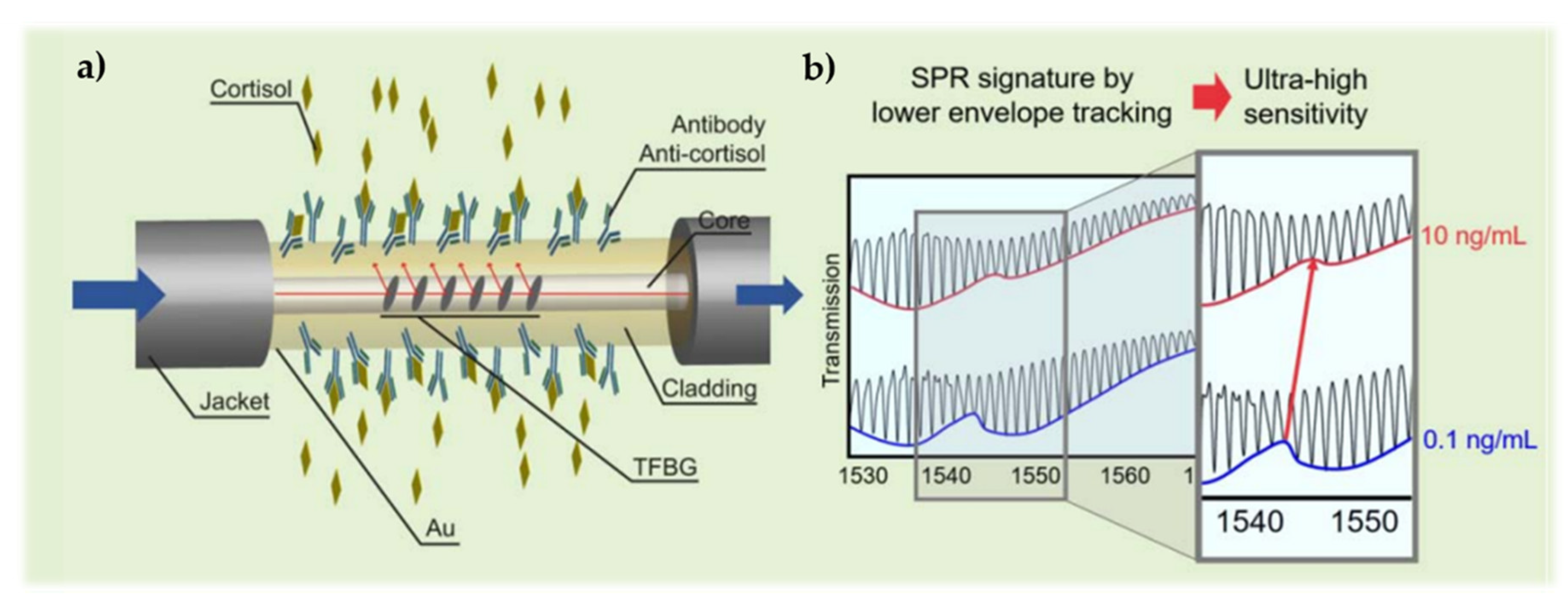
4.2.3. Stress Biomarkers
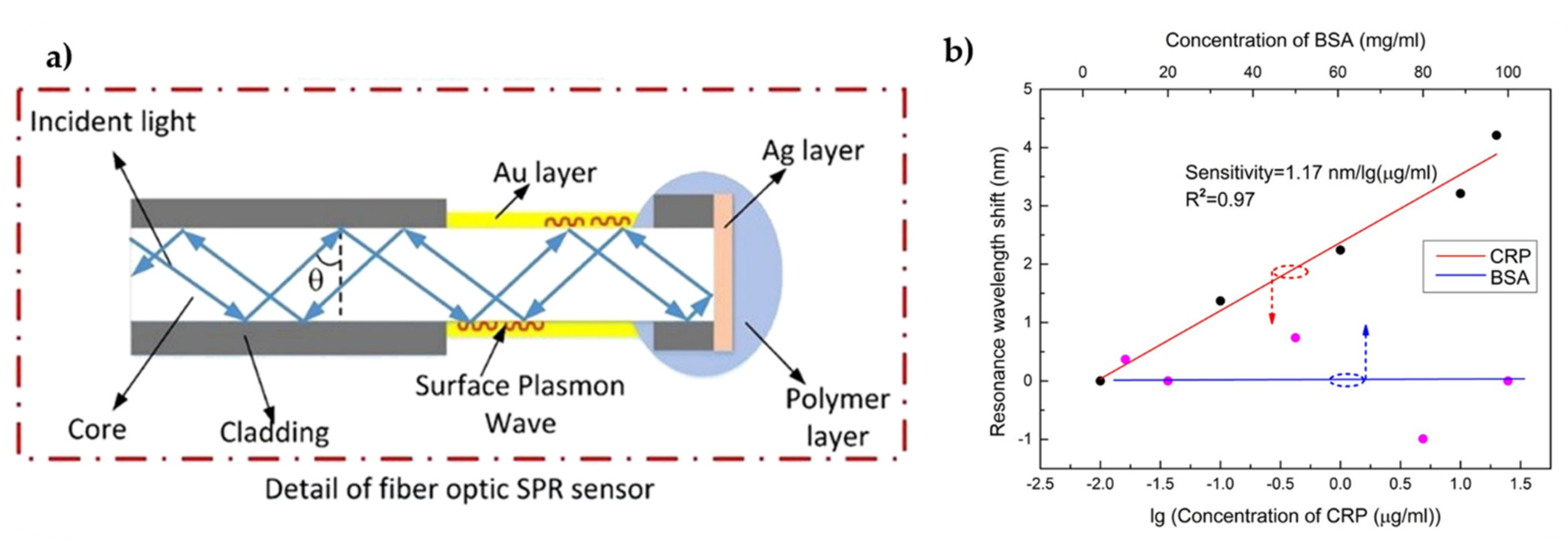
4.2.4. Inflammatory Biomarkers
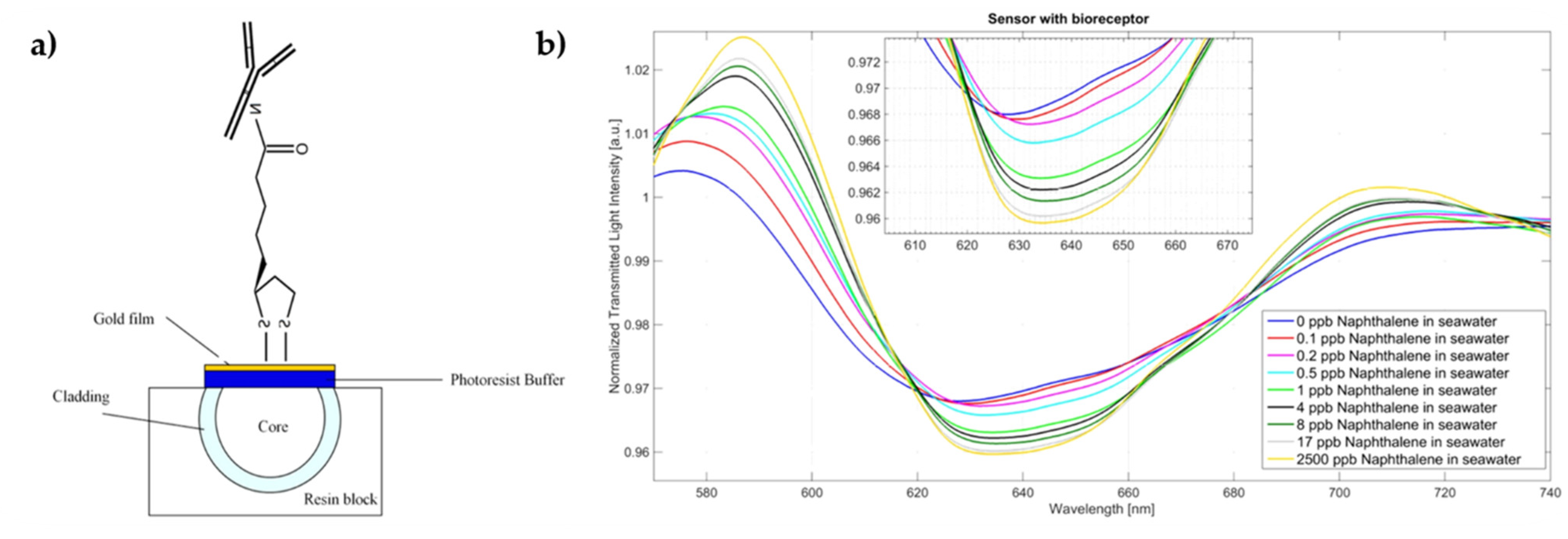
4.3. Environmental Monitoring
5. Final Remarks and Future Outlook
Author Contributions
Funding
Data Availability Statement
Conflicts of Interest
References
- Lo Presti, D.; Massaroni, C.; Leitao, C.; de Fatima Domingues, M.; Sypabekova, M.; Barrera, D.; Floris, I.; Massari, L.; Oddo, C.M.; Sales, S.; et al. Fiber bragg gratings for medical applications and future challenges: A review. IEEE Access 2020, 8, 156863–156888. [Google Scholar] [CrossRef]
- Cennamo, N.; Pesavento, M.; Zeni, L. A review on simple and highly sensitive plastic optical fiber probes for bio-chemical sensing. Sens. Actuators B Chem. 2021, 331, 129393. [Google Scholar] [CrossRef]
- Joe, H.-E.; Yun, H.; Jo, S.-H.; Jun, M.B.G.; Min, B.-K. A review on optical fiber sensors for environmental monitoring. Int. J. Precis. Eng. Manuf. Technol. 2018, 5, 173–191. [Google Scholar] [CrossRef]
- Tosi, D.; Poeggel, S.; Iordachita, I.; Schena, E. Fiber Optic Sensors for Biomedical Applications. Opto-Mech. Fiber Opt. Sens. Res. Technol. Appl. Mech. Sens. 2018, 301–333. [Google Scholar] [CrossRef]
- Adányi, N.; Majer-Baranyi, K.; Székács, A. Evanescent field effect–based nanobiosensors for agro-environmental and food safety. In Nanobiosensors; Academic Press: Cambridge, Mass, USA, 2017; pp. 429–474. [Google Scholar] [CrossRef]
- Desmet, C.; Vindas, K.; Meza, R.A.; Garrigue, P.; Voci, S.; Sojic, N.; Maziz, A.; Courson, R.; Malaquin, L.; Leichle, T.; et al. Multiplexed Remote SPR Detection of Biological Interactions through Optical Fiber Bundles. Sensors 2020, 20, 511. [Google Scholar] [CrossRef] [PubMed] [Green Version]
- Yin, M.J.; Gu, B.; An, Q.F.; Yang, C.; Guan, Y.L.; Yong, K.T. Recent development of fiber-optic chemical sensors and biosensors: Mechanisms, materials, micro/nano-fabrications and applications. Coord. Chem. Rev. 2018, 376, 348–392. [Google Scholar] [CrossRef]
- Monfared, Y.E. Overview of recent advances in the design of plasmonic fiber-optic biosensors. Biosensors 2020, 10, 77. [Google Scholar] [CrossRef]
- Marazuela, M.D.; Moreno-bondi, M.C. Fiber-optic biosensors—An overview. Anal. Bioanal. Chem. 2002, 372, 664–682. [Google Scholar] [CrossRef]
- Jorgenson, R.C.; Yee, S.S. A fiber-optic chemical sensor based on surface plasmon resonance. Sens. Actuators B. Chem. 1993, 12, 213–220. [Google Scholar] [CrossRef]
- Zhao, Y.; Tong, R.J.; Xia, F.; Peng, Y. Current status of optical fiber biosensor based on surface plasmon resonance. Biosens. Bioelectron. 2019, 142, 111505. [Google Scholar] [CrossRef]
- Wu, S.-Y.; Hulme, J.; An, S.S.A. Recent trends in the detection of pathogenic Escherichia coli O157: H7. BioChip J. 2015, 9, 173–181. [Google Scholar] [CrossRef]
- Luo, B.; Xu, Y.; Wu, S.; Zhao, M.; Jiang, P.; Shi, S.; Zhang, Z.; Wang, Y.; Wang, L.; Liu, Y. A novel immunosensor based on excessively tilted fiber grating coated with gold nanospheres improves the detection limit of Newcastle disease virus. Biosens. Bioelectron. 2018, 100, 169–175. [Google Scholar] [CrossRef]
- Mustapha Kamil, Y.; Abu Bakar, M.H.; Mustapa, M.A.; Yaacob, M.H.; Abidin, N.H.Z.; Syahir, A.; Lee, H.J.; Mahdi, M.A. Label-free Dengue E protein detection using a functionalized tapered optical fiber sensor. Sens. Actuators B Chem. 2018, 257, 820–828. [Google Scholar] [CrossRef]
- Nguyen, H.H.; Lee, S.H.; Lee, U.J.; Fermin, C.D.; Kim, M. Immobilized Enzymes in Biosensor Applications. Materials 2019, 12, 121. [Google Scholar] [CrossRef] [PubMed] [Green Version]
- Cristea, C.; Florea, A.; Tertiș, M.; Săndulescu, R. Immunosensors; IntechOpen: London, UK, 2015. [Google Scholar]
- Naresh, V.; Lee, N. A Review on Biosensors and Recent Development of Nanostructured Materials-Enabled Biosensors. Sensors 2021, 21, 1109. [Google Scholar] [CrossRef]
- Mahmoudpour, M.; Dolatabadi, J.E.N.; Torbati, M.; Homayouni-Rad, A. Nanomaterials based surface plasmon resonance signal enhancement for detection of environmental pollutions. Biosens. Bioelectron. 2019, 127, 72–84. [Google Scholar] [CrossRef]
- Leung, A.; Shankar, P.M.; Mutharasan, R. A review of fiber-optic biosensors. Sens. Actuators B Chem. 2007, 125, 688–703. [Google Scholar] [CrossRef]
- González-Vila, Á.; Debliquy, M.; Lahem, D.; Zhang, C.; Mégret, P.; Caucheteur, C. Molecularly imprinted electropolymerization on a metal-coated optical fiber for gas sensing applications. Sens. Actuators B Chem. 2017, 244, 1145–1151. [Google Scholar] [CrossRef]
- Malhotra, B.D.; Ali, M.A. Nanomaterials in Biosensors: Fundamentals and Applications. In Nanomaterials for Biosensors; Elsevier: Amsterdam, The Netherlands, 2018; pp. 1–74. [Google Scholar]
- Hernaez, M.; Zamarreño, C.R.; Melendi-Espina, S.; Bird, L.R.; Mayes, A.G.; Arregui, F.J. Optical fibre sensors using graphene-based materials: A review. Sensors 2017, 17, 155. [Google Scholar] [CrossRef] [PubMed] [Green Version]
- Liedberg, B.; Nylander, C.; Lunström, I. Surface plasmon resonance for gas detection and biosensing. Sens. Actuators 1983, 4, 299–304. [Google Scholar] [CrossRef]
- Aruna Gandhi, M.S.; Chu, S.; Senthilnathan, K.; Babu, P.R.; Nakkeeran, K.; Li, Q. Recent advances in plasmonic sensor-based fiber optic probes for biological applications. Appl. Sci. 2019, 9, 949. [Google Scholar] [CrossRef] [Green Version]
- Chiu, N.F.; Yang, C.D.; Chen, C.C.; Lin, T.L.; Kuo, C.T. Functionalization of Graphene and Graphene Oxide for Plasmonic and Biosensing Applications; Elsevier Inc.: Amsterdam, The Netherlands, 2018; ISBN 9780128133507. [Google Scholar]
- Guo, T.; González-Vila, Á.; Loyez, M.; Caucheteur, C. Plasmonic optical fiber-grating Immunosensing: A review. Sensors 2017, 17, 2732. [Google Scholar] [CrossRef] [PubMed] [Green Version]
- Harpaz, D.; Koh, B.; Seet, R.C.S.; Abdulhalim, I.; Tok, A.I.Y. Functionalized silicon dioxide self-referenced plasmonic chip as point-of-care biosensor for stroke biomarkers NT-proBNP and S100β. Talanta 2020, 212, 1–11. [Google Scholar] [CrossRef]
- Luo, W.; Wang, R.; Li, H.; Kou, J.; Zeng, X.; Huang, H.; Hu, X.; Huang, W. Simultaneous measurement of refractive index and temperature based on surface plasmon resonance sensors. Opt. Express 2019, 27, 576–589. [Google Scholar] [CrossRef] [PubMed]
- Zhao, X.; Tsao, Y.C.; Lee, F.J.; Tsai, W.H.; Wang, C.H.; Chuang, T.L.; Wu, M.S.; Lin, C.W. Optical fiber sensor based on surface plasmon resonance for rapid detection of avian influenza virus subtype H6: Initial studies. J. Virol. Methods 2016, 233, 15–22. [Google Scholar] [CrossRef]
- Wang, W.; Mai, Z.; Chen, Y.; Wang, J.; Li, L.; Su, Q.; Li, X.; Hong, X. A label-free fiber optic SPR biosensor for specific detection of C-reactive protein. Sci. Rep. 2017, 7, 1–8. [Google Scholar] [CrossRef]
- da S Arcas, A.; da S Dutra, F.; Allil, R.C.S.B.; Werneck, M.M. Surface plasmon resonance and bending loss-based U-shaped plastic optical fiber biosensors. Sensors 2018, 18, 648. [Google Scholar] [CrossRef] [Green Version]
- Semwal, V.; Gupta, B.D. Highly selective SPR based fiber optic sensor for the detection of hydrogen peroxide. Sens. Actuators B Chem. 2020, 129062. [Google Scholar] [CrossRef]
- Seo, M.; Lee, J.; Lee, M. Grating-coupled surface plasmon resonance on bulk stainless steel. Opt. Express 2017, 25, 26939–26949. [Google Scholar] [CrossRef] [PubMed]
- Joseph, S.; Sarkar, S.; Joseph, J. Grating-coupled surface plasmon-polariton sensing at a flat metal-analyte interface in a hybrid-configuration. ACS Appl. Mater. Interfaces 2020, 12, 1–32. [Google Scholar] [CrossRef]
- Prabowo, B.A.; Purwidyantri, A.; Liu, K.C. Surface plasmon resonance optical sensor: A review on light source technology. Biosensors 2018, 8, 80. [Google Scholar] [CrossRef] [PubMed] [Green Version]
- Caucheteur, C.; Guo, T.; Albert, J. Review of plasmonic fiber optic biochemical sensors: Improving the limit of detection. Anal. Bioanal. Chem. 2015, 407, 3883–3897. [Google Scholar] [CrossRef] [PubMed]
- Qi, M.; Zhang, N.M.Y.; Li, K.; Tjin, S.C.; Wei, L. Hybrid Plasmonic Fiber-Optic Sensors. Sensors 2020, 20, 3266. [Google Scholar] [CrossRef]
- Gowri, A.; Sai, V.V.R. Development of LSPR based U-bent plastic optical fiber sensors. Sens. Actuators B. Chem. 2016, 230, 536–543. [Google Scholar] [CrossRef]
- Sharma, P.; Semwal, V.; Gupta, B.D. A highly selective LSPR biosensor for the detection of taurine realized on optical fiber substrate and gold nanoparticles. Opt. Fiber Technol. 2019, 52, 1–6. [Google Scholar] [CrossRef]
- Dash, J.N.; Jha, R. Graphene-based birefringent photonic crystal fiber sensor using surface plasmon resonance. IEEE Photonics Technol. Lett. 2014, 26, 1–4. [Google Scholar] [CrossRef]
- Tien, C.; Lin, H.; Su, S. High Sensitivity Refractive Index Sensor by D-Shaped Fibers and Titanium Dioxide Nanofilm. Adv. Condens. Matter Phys. 2018, 2018, 6. [Google Scholar] [CrossRef] [Green Version]
- Giurgiutiu, V. Fiber-Optic Sensors; CRC Press: Boca Raton, FL, USA, 2016; ISBN 978-0-12-409605-9. [Google Scholar]
- Rifat, A.A.; Ahmed, R.; Yetisen, A.K.; Butt, H.; Sabouri, A.; Mahdiraji, G.A.; Yun, S.H.; Adikan, F.R.M. Photonic crystal fiber based plasmonic sensors. Sens. Actuators B Chem. 2017, 243, 311–325. [Google Scholar] [CrossRef]
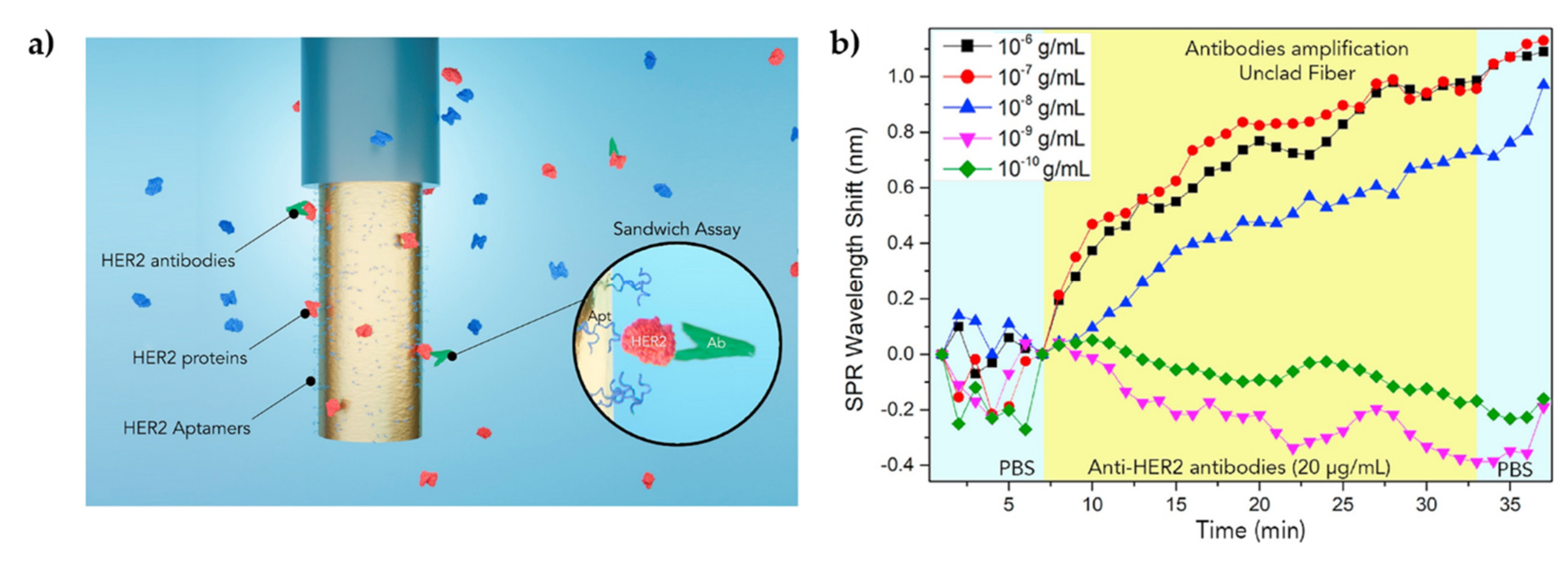
- Loyez, M.; Lobry, M.; Hassan, E.M.; DeRosa, M.C.; Caucheteur, C.; Wattiez, R. HER2 breast cancer biomarker detection using a sandwich optical fiber assay. Talanta 2021, 221, 121452. [Google Scholar] [CrossRef] [PubMed]
- Kulyk, B.; Freitas, M.A.; Santos, N.F.; Mohseni, F.; Carvalho, A.F.; Yasakau, K.; Fernandes, A.J.S.; Bernardes, A.; Figueiredo, B.; Silva, R.; et al. A critical review on the production and application of graphene and graphene-based materials in anti-corrosion coatings. Crit. Rev. Solid State Mater. Sci. 2021, 1–48. [Google Scholar] [CrossRef]
- Jiang, S.; Li, Z.; Zhang, C.; Gao, S.; Li, Z.; Qiu, H.; Li, C.; Yang, C.; Liu, M.; Liu, Y. A novel U-bent plastic optical fibre local surface plasmon resonance sensor based on a graphene and silver nanoparticle hybrid structure. J. Phys. D Appl. Phys. 2017, 50, 165105. [Google Scholar] [CrossRef]
- Wang, Q.; Wang, B.T. Surface plasmon resonance biosensor based on graphene oxide/silver coated polymer cladding silica fiber. Sens. Actuators B Chem. 2018, 275, 332–338. [Google Scholar] [CrossRef]
- Wang, Q.; Jiang, X.; Niu, L.; Fan, X. Enhanced sensitivity of bimetallic optical fiber SPR sensor based on MoS2 nanosheets. Opt. Lasers Eng. 2020, 128, 105997. [Google Scholar] [CrossRef]
- Kim, H.M.; Park, J.H.; Lee, S.K. Fiber optic sensor based on ZnO nanowires decorated by Au nanoparticles for improved plasmonic biosensor. Sci. Rep. 2019, 9, 15605. [Google Scholar] [CrossRef] [Green Version]
- Tahhan, S.R.; Chen, R.Z.; Huang, S.; Hajim, K.I.; Chen, K.P. Fabrication of Fiber Bragg Grating Coating with TiO2 Nanostructured Metal Oxide for Refractive Index Sensor. J. Nanotechnol. 2017, 2017, 9. [Google Scholar] [CrossRef] [Green Version]
- Esfahani Monfared, Y. Refractive Index Sensor Based on Surface Plasmon Resonance Excitation in a D-Shaped Photonic Crystal Fiber Coated by Titanium Nitride. Plasmonics 2020, 15, 535–542. [Google Scholar] [CrossRef]
- Chauhan, M.; Kumar Singh, V. Review on recent experimental SPR/LSPR based fiber optic analyte sensors. Opt. Fiber Technol. 2021, 64, 102580. [Google Scholar] [CrossRef]
- Kadhum Hisham, H. Optical Fiber Sensing Technology: Basics, Classifications and Applications. Am. J. Remote Sens. 2018, 6, 1. [Google Scholar] [CrossRef]
- Lopes, R.N.; Rodrigues, D.M.C.; Allil, R.C.S.B.; Werneck, M.M. Plastic optical fiber immunosensor for fast detection of sulfate-reducing bacteria. Measurement 2018, 125, 377–385. [Google Scholar] [CrossRef]
- Sridevi, S.; Vasu, K.S.; Sampath, S.; Asokan, S.; Sood, A.K. Optical detection of glucose and glycated hemoglobin using etched fiber Bragg gratings coated with functionalized reduced graphene oxide. J. Biophotonics 2016, 9, 760–769. [Google Scholar] [CrossRef]
- Cennamo, N.; Zeni, L.; Ricca, E.; Isticato, R.; Marzullo, V.M.; Capo, A.; Staiano, M.; D’Auria, S.; Varriale, A. Detection of naphthalene in sea-water by a label-free plasmonic optical fiber biosensor. Talanta 2019, 194, 289–297. [Google Scholar] [CrossRef]
- Khalaf, A.L.; Arasu, P.T.; Lim, H.N.; Paiman, S.; Yusof, N.A.; Mahdi, M.A.; Yaacob, M.H. Modified plastic optical fiber with CNT and graphene oxide nanostructured coatings for ethanol liquid sensing. Opt. Express 2017, 25, 12. [Google Scholar] [CrossRef] [Green Version]
- Sypabekova, M.; Aitkulov, A.; Blanc, W.; Tosi, D. Reflector-less nanoparticles doped optical fiber biosensor for the detection of proteins: Case thrombin. Biosens. Bioelectron. 2020, 165, 9. [Google Scholar] [CrossRef] [PubMed]
- Azkune, M.; Ruiz-Rubio, L.; Aldabaldetreku, G.; Arrospide, E.; Pérez-Álvarez, L.; Bikandi, I.; Zubia, J.; Vilas-Vilela, J.L. U-shaped and Surface Functionalized Polymer Optical Fiber Probe for Glucose Detection. Sensors 2018, 18, 34. [Google Scholar] [CrossRef] [PubMed] [Green Version]
- Manoharan, H.; Kalita, P.; Gupta, S.; Sai, V.V.R. Plasmonic biosensors for bacterial endotoxin detection on biomimetic C-18 supported fiber optic probes. Biosens. Bioelectron. 2019, 129, 79–86. [Google Scholar] [CrossRef] [PubMed]
- Khijwania, S.K.; Gupta, B.D. Maximum achievable sensitivity of the fiber optic evanescent field absorption sensor based on the U-shaped probe. Opt. Commun. 2000, 175, 135–137. [Google Scholar] [CrossRef]
- Gasior, K.; Martynkien, T.; Wojcik, G.; Mergo, P.; Urbanczyk, W. D-shape polymer optical fibres for surface plasmon resonance sensing. Opto-Electron. Rev. 2017, 25, 1–5. [Google Scholar] [CrossRef]
- Cennamo, N.; D’Agostino, G.; Pesavento, M.; Zeni, L. High selectivity and sensitivity sensor based on MIP and SPR in tapered plastic optical fibers for the detection of l-nicotine. Sens. Actuators B Chem. 2014, 191, 529–536. [Google Scholar] [CrossRef]
- Yang, Q.; Zhu, G.; Singh, L.; Wang, Y.; Singh, R.; Zhang, B.; Zhang, X.; Kumar, S. Highly sensitive and selective sensor probe using glucose oxidase/gold nanoparticles/graphene oxide functionalized tapered optical fiber structure for detection of glucose. Optik 2020, 208, 164536. [Google Scholar] [CrossRef]
- Wei, W.; Nong, J.; Zhu, Y.; Zhang, G.; Wang, N.; Luo, S.; Chen, N.; Lan, G.; Chuang, C.J.; Huang, Y. Graphene/Au-Enhanced Plastic Clad Silica Fiber Optic Surface Plasmon Resonance Sensor. Plasmonics 2018, 13, 483–491. [Google Scholar] [CrossRef]
- Hill, K.O.; Fujii, Y.; Johnson, D.C.; Kawasaki, B.S. Photosensitivity in optical fiber waveguides: Application to reflection filter fabrication. Appl. Phys. Lett. 1978, 32, 647–649. [Google Scholar] [CrossRef]
- Majumder, M.; Gangopadhyay, T.K.; Chakraborty, A.K.; Dasgupta, K.; Bhattacharya, D.K. Fibre Bragg gratings in structural health monitoring-Present status and applications. Sens. Actuators A Phys. 2008, 147, 150–164. [Google Scholar] [CrossRef]
- Othonos, A.; Kalli, K. Fiber Bragg Gratings: Fundamentals and Applications in Telecommunications and Sensing; Artech House: Boston, FL, USA, 1999; ISBN 0890063443. [Google Scholar]
- Meltz, G.; Morey, W.W.; Glenn, W.H. Formation of Bragg gratings in optical fibers by a transverse holographic method. Opt. Lett. 1989, 14, 823. [Google Scholar] [CrossRef] [PubMed]
- Geernaert, T.; Kalli, K.; Koutsides, C.; Komodromos, M.; Nasilowski, T.; Urbanczyk, W.; Wojcik, J.; Berghmans, F.; Thienpont, H. Point-by-point fiber Bragg grating inscription in free-standing step-index and photonic crystal fibers using near-IR femtosecond laser. Opt. Lett. 2010, 35, 1647–1649. [Google Scholar] [CrossRef]
- Theodosiou, A.; Lacraz, A.; Stassis, A.; Koutsides, C.; Komodromos, M.; Kalli, K. Plane-by-Plane Femtosecond Laser Inscription Method for Single-Peak Bragg Gratings in Multimode CYTOP Polymer Optical Fiber. J. Light. Technol. 2017, 35, 5404–5410. [Google Scholar] [CrossRef]
- James, S.W.; Tatam, R.P. Optical fibre long-period grating sensors: Characteristics and application. Meas. Sci. Technol. 2003, 14, 49–61. [Google Scholar] [CrossRef] [Green Version]
- Iadicicco, A.; Campopiano, S.; Cutolo, A.; Giordano, M.; Cusano, A. Thinned fiber Bragg gratings for sensing applications. In Proceedings of the 2005 IEEE/LEOS Workshop on Fibres and Optical Passive Components, Palermo, Italy, 22–24 June 2005; Volume 2005, pp. 204–209. [Google Scholar] [CrossRef]
- Chiavaioli, F.; Baldini, F.; Tombelli, S.; Trono, C.; Giannetti, A. Biosensing with optical fiber gratings. Nanophotonics 2017, 6, 663–679. [Google Scholar] [CrossRef]
- Wang, R.; Ren, Z.; Kong, D.; Hu, B.; He, Z. Highly sensitive label-free biosensor based on graphene-oxide functionalized micro-tapered long period fiber grating. Opt. Mater. 2020, 109, 110253. [Google Scholar] [CrossRef]
- Zuber, A.A.; Klantsataya, E.; Bachhuka, A. Biosensing. Compr. Nanosci. Nanotechnol. 2019, 1–5, 105–126. [Google Scholar] [CrossRef]
- Berghmans, F.; Geernaert, T.; Baghdasaryan, T.; Thienpont, H. Challenges in the fabrication of fibre Bragg gratings in silica and polymer microstructured optical fibres. Laser Photonics Rev. 2014, 8, 27–52. [Google Scholar] [CrossRef]
- Liu, Z.; Tam, H.Y.; Htein, L.; Tse, M.L.V.; Lu, C. Microstructured Optical Fiber Sensors. J. Light. Technol. 2017, 35, 3425–3439. [Google Scholar] [CrossRef]
- Han, H.; Hou, D.; Zhao, L.; Luan, N.; Song, L.; Liu, Z.; Lian, Y.; Liu, J.; Hu, Y. A Large Detection-Range Plasmonic Sensor Based on An H-Shaped Photonic Crystal Fiber. Sensors 2020, 20, 1009. [Google Scholar] [CrossRef] [PubMed] [Green Version]
- Armbruster, D.A.; Pry, T. Limit of Blank, Limit of Detection and Limit of Quantitation. Clin. Biochem. Rev. 2008, 29, S49–S52. [Google Scholar] [PubMed]
- Justino, C.I.L.; Duarte, A.C.; Rocha-santos, T.A.P. Critical overview on the application of sensors and biosensors for clinical analysis. Trends Anal. Chem. 2016, 85, 36–60. [Google Scholar] [CrossRef]
- Shrivastava, A.; Gupta, V. Methods for the determination of limit of detection and limit of quantitation of the analytical methods. Chron. Young Sci. 2011, 2, 21. [Google Scholar] [CrossRef]
- Harpaz, D.; Koh, B.; Marks, R.S.; Seet, R.C.S.; Abdulhalim, I.; Tok, A.I.Y. Point-of-Care Surface Plasmon Resonance Biosensor for Stroke Biomarkers NT-proBNP and S100β Using a Functionalized Gold Chip with Specific Antibody. Sensors 2019, 19, 2533. [Google Scholar] [CrossRef] [Green Version]
- Leitão, C.; Leal-Junior, A.; Almeida, A.R.; Pereira, S.O.; Costa, F.M.; Pinto, J.L.; Marques, C. Cortisol AuPd plasmonic unclad POF biosensor. Biotechnol. Rep. 2021, 29, 6. [Google Scholar] [CrossRef]
- Tabassum, R.; Gupta, B.D. Simultaneous estimation of vitamin K1 and heparin with low limit of detection using cascaded channels fiber optic surface plasmon resonance. Biosens. Bioelectron. 2016, 86, 48–55. [Google Scholar] [CrossRef]
- Lara, S.; Perez-Potti, A. Applications of nanomaterials for immunosensing. Biosensors 2018, 8, 104. [Google Scholar] [CrossRef] [Green Version]
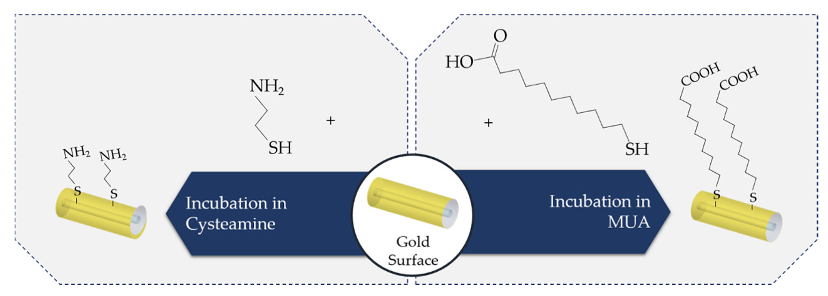
- Fratila, R.M.; Mitchell, S.G.; del Pino, P.; Grazu, V.; de la Fuente, J.M. Strategies for the Biofunctionalization of Gold and Iron Oxide Nanoparticles. Langmuir 2014, 30, 15057–15071. [Google Scholar] [CrossRef]
- Ko, S.; Grant, S.A. A novel FRET-based optical fiber biosensor for rapid detection of Salmonella typhimurium. Biosens. Bioelectron. 2006, 21, 1283–1290. [Google Scholar] [CrossRef] [PubMed]
- Malachovská, V.; Ribaut, C.; Voisin, V.; Surin, M.; Leclère, P.; Wattiez, R.; Caucheteur, C. Fiber-Optic SPR Immunosensors Tailored To Target Epithelial Cells through Membrane Receptors. Anal. Chem. 2015, 87, 5957–5965. [Google Scholar] [CrossRef]
- Trilling, A.K.; Beekwilder, J.; Zuilhof, H. Antibody orientation on biosensor surfaces: A minireview. Analyst 2013, 138, 1619. [Google Scholar] [CrossRef] [PubMed] [Green Version]
- Hermanson, G.T. Bioconjugate Techniques, 2nd ed.; Elsevier: Amsterdam, The Netherlands, 2008. [Google Scholar]
- Leitao, C.; Pereira, S.O.; Alberto, N.; Lobry, M.; Loyez, M.; Costa, F.M.; Pinto, J.L.; Caucheteur, C.; Marques, C. Cortisol In-Fiber Ultrasensitive Plasmonic Immunosensing. IEEE Sens. J. 2021, 21, 3028–3034. [Google Scholar] [CrossRef]
- Sun, D.; Ran, Y.; Wang, G. Label-free detection of cancer biomarkers using an in-line taper fiber-optic interferometer and a fiber bragg grating. Sensors 2017, 17, 2559. [Google Scholar] [CrossRef] [Green Version]
- Loyez, M.; Albert, J.; Caucheteur, C.; Wattiez, R. Cytokeratins biosensing using tilted fiber gratings. Biosensors 2018, 8, 8. [Google Scholar] [CrossRef] [Green Version]
- Fixe, F.; Dufva, M.; Telleman, P.; Christensen, C.B. Functionalization of poly(methyl methacrylate) (PMMA) as a substrate for DNA microarrays. Nucleic Acids Res. 2004, 32, 1–8. [Google Scholar] [CrossRef] [PubMed] [Green Version]
- Wang, B.T.; Wang, Q. Sensitivity-Enhanced Optical Fiber Biosensor Based on Coupling Effect between SPR and LSPR. IEEE Sens. J. 2018, 18, 8303–8310. [Google Scholar] [CrossRef]
- Wang, Q.; Wang, B. Sensitivity enhanced SPR immunosensor based on graphene oxide and SPA co-modified photonic crystal fiber. Opt. Laser Technol. 2018, 107, 210–215. [Google Scholar] [CrossRef]
- Maya, Y.C.; Del Villar, I.; Socorro, A.B.; Corres, J.M.; Botero-Cadavid, J.F. Optical Fiber Immunosensors Optimized with Cladding Etching and ITO Nanodeposition. In Proceedings of the 2018 IEEE Photonics Conference (IPC), Reston, VA, USA, 30 September–4 October 2018; pp. 4–5. [Google Scholar] [CrossRef] [Green Version]
- George, A.; Amrutha, M.S.; Srivastava, P.; Sunil, S.; Sai, V.V.R.; Srinivasan, R. Development of a U-bent plastic optical fiber biosensor with plasmonic labels for the detection of chikungunya non-structural protein 3. Analyst 2021, 146, 244–252. [Google Scholar] [CrossRef] [PubMed]
- Liu, Y.; Yu, J. Oriented immobilization of proteins on solid supports for use in biosensors and biochips: A review. Microchim. Acta 2016, 183, 1–19. [Google Scholar] [CrossRef]
- Srinivasan, R.; Umesh, S.; Murali, S.; Asokan, S.; Siva Gorthi, S. Bare fiber Bragg grating immunosensor for real-time detection of Escherichia coli bacteria. J. Biophotonics 2017, 10, 224–230. [Google Scholar] [CrossRef] [PubMed]
- Xiao, P.; Sun, Z.; Huang, Y.; Lin, W.; Ge, Y.; Xiao, R.; Li, K.; Li, Z.; Lu, H.; Yang, M.; et al. Development of an optical microfiber immunosensor for prostate specific antigen analysis using a high-order-diffraction long period grating. Opt. Express 2020, 28, 11. [Google Scholar] [CrossRef] [PubMed]
- Tang, M.; Wu, Y.; Deng, D.; Wei, J.; Zhang, J.; Yang, D.; Li, G. Development of an optical fiber immunosensor for the rapid and sensitive detection of phthalate esters. Sens. Actuators B Chem. 2018, 258, 304–312. [Google Scholar] [CrossRef]
- Janczuk-Richter, M.; Gromadzka, B.; Richter, Ł.; Panasiuk, M.; Zimmer, K.; Mikulic, P.; Bock, W.J.; Maćkowski, S.; Śmietana, M.; Jönsson, J.N. Immunosensor based on long-period fiber gratings for detection of viruses causing gastroenteritis. Sensors 2020, 20, 813. [Google Scholar] [CrossRef] [Green Version]
- Algaar, F.; Eltzov, E.; Vdovenko, M.M.; Sakharov, I.Y.; Fajs, L.; Weidmann, M.; Mirazimi, A.; Marks, R.S. Fiber-Optic Immunosensor for Detection of Crimean-Congo Hemorrhagic Fever IgG Antibodies in Patients. Anal. Chem. 2015, 87, 5. [Google Scholar] [CrossRef]
- Xu, X.; Nie, R.; Huang, J.; Yang, L. Chemiluminescent Optical Fiber Immunosensor Combining Surface Modification and Signal Amplification for Ultrasensitive Determination of Hepatitis B Antigen. Sensors 2020, 20, 4912. [Google Scholar] [CrossRef]
- Liu, X.; Song, X.; Dong, Z.; Meng, X.; Chen, Y.; Yang, L. Photonic crystal fiber-based immunosensor for high-performance detection of alpha fetoprotein. Biosens. Bioelectron. 2017, 91, 431–435. [Google Scholar] [CrossRef]
- Li, K.; Zhang, N.; Ying Zhang, N.M.; Zhou, W.; Zhang, T.; Chen, M.; Wei, L. Birefringence induced Vernier effect in optical fiber modal interferometers for enhanced sensing. Sensors Actuators, B Chem. 2018, 275, 16–24. [Google Scholar] [CrossRef]
- Liu, T.; Liang, L.; Xiao, P.; Sun, L.; Huang, Y.; Ran, Y.; Jin, L. A label-free cardiac biomarker immunosensor based on phase-shifted micro fiber Bragg grating. Biosens. Bioelectron. 2018, 100, 155–160. [Google Scholar] [CrossRef]
- Chang, T.C.; Chiang, C.Y.; Lin, M.H.; Chen, I.K.; Chau, L.K.; Hsu, D.S.; Shieh, S.S.; Kuo, C.J.; Wang, S.C.; Chen, Y. fou Fiber optic particle plasmon resonance immunosensor for rapid and sensitive detection of methamphetamine based on competitive inhibition. Microchem. J. 2020, 157, 6. [Google Scholar] [CrossRef]
- Esposito, F.; Sansone, L.; Srivastava, A.; Baldini, F.; Campopiano, S.; Chiavaioli, F.; Giordano, M.; Giannetti, A.; Iadicicco, A. Long period grating in double cladding fiber coated with graphene oxide as high-performance optical platform for biosensing. Biosens. Bioelectron. 2021, 172, 112747. [Google Scholar] [CrossRef] [PubMed]
- Sridevi, S.; Vasu, K.S.; Asokan, S.; Sood, A.K. Sensitive detection of C-reactive protein using optical fiber Bragg gratings. Biosens. Bioelectron. 2015, 65, 251–256. [Google Scholar] [CrossRef] [PubMed]
- Kaushik, S.; Tiwari, U.K.; Deep, A.; Sinha, R.K. Two-dimensional transition metal dichalcogenides assisted biofunctionalized optical fiber SPR biosensor for efficient and rapid detection of bovine serum albumin. Sci. Rep. 2019, 9, 1–11. [Google Scholar] [CrossRef] [Green Version]
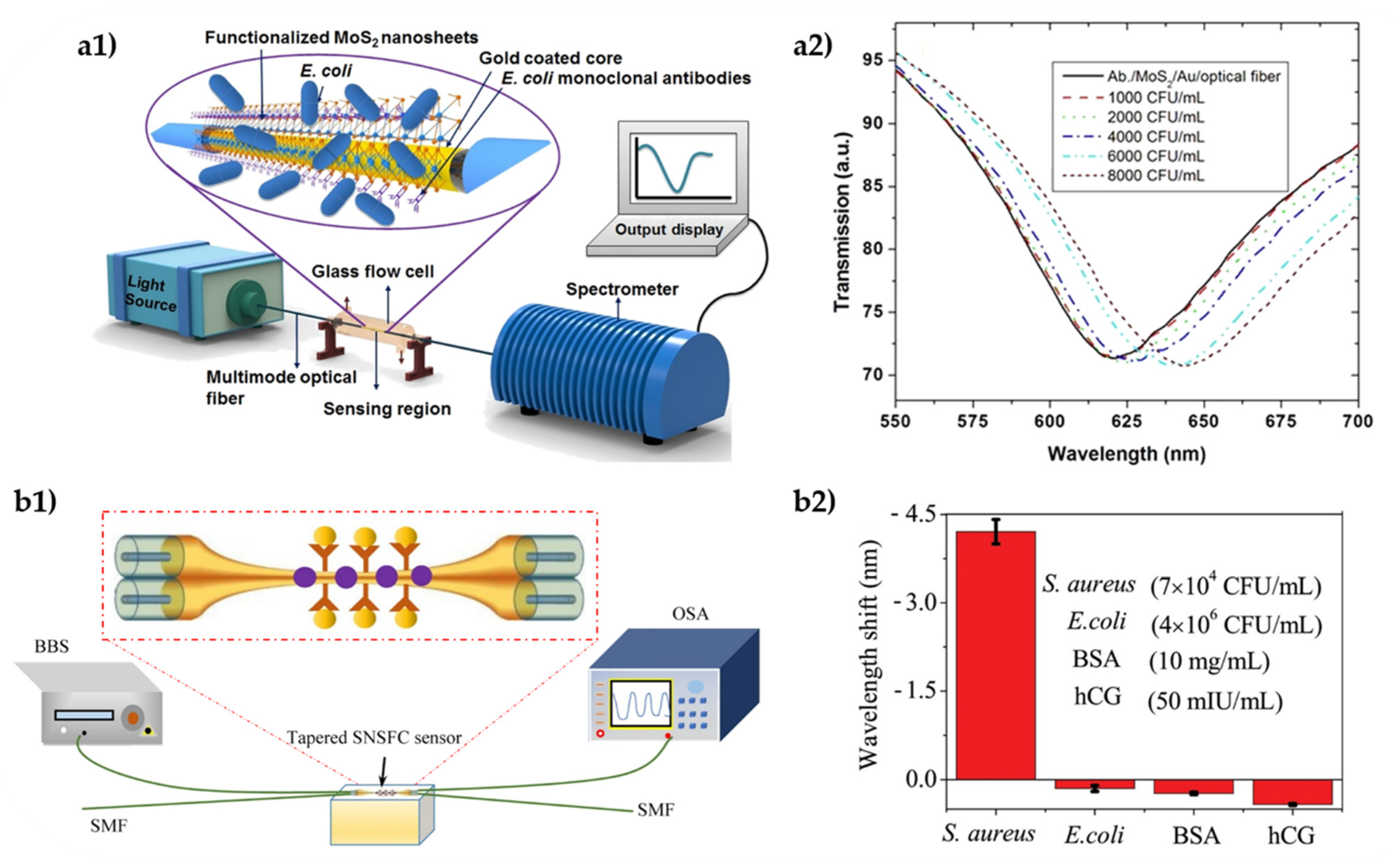
- Kaushik, S.; Tiwari, U.K.; Sudipta, S.; Sinha, R.K. Rapid detection of Escherichia coli using fiber optic surface plasmon resonance immunosensor based on biofunctionalized Molybdenum disulfide (MoS2) nanosheets. Biosens. Bioelectron. 2019, 126, 501–509. [Google Scholar] [CrossRef]
- Viter, R.; Savchuk, M.; Iatsunskyi, I.; Pietralik, Z.; Starodub, N.; Shpyrka, N.; Ramanaviciene, A.; Ramanavicius, A. Analytical, thermodynamical and kinetic characteristics of photoluminescence immunosensor for the determination of Ochratoxin A. Biosens. Bioelectron. 2018, 99, 237–243. [Google Scholar] [CrossRef]
- Myndrul, V.; Coy, E.; Bechelany, M.; Iatsunskyi, I. Photoluminescence label-free immunosensor for the detection of Aflatoxin B1 using polyacrylonitrile/zinc oxide nanofibers. Mater. Sci. Eng. C 2021, 118, 12. [Google Scholar] [CrossRef]
- Eftimov, T.; Janik, M.; Koba, M.; Smietana, M.; Mikulic, P.; Bock, W. Long-Period Gratings and Microcavity In-Line Mach Zehnder Interferometers as Highly Sensitive Optical Fiber Platforms for Bacteria Sensing. Sensors 2020, 20, 3772. [Google Scholar] [CrossRef]
- Kaushik, S.; Pandey, A.; Tiwari, U.K.; Sinha, R.K. A label-free fiber optic biosensor for Salmonella Typhimurium detection. Opt. Fiber Technol. 2018, 46, 95–103. [Google Scholar] [CrossRef]
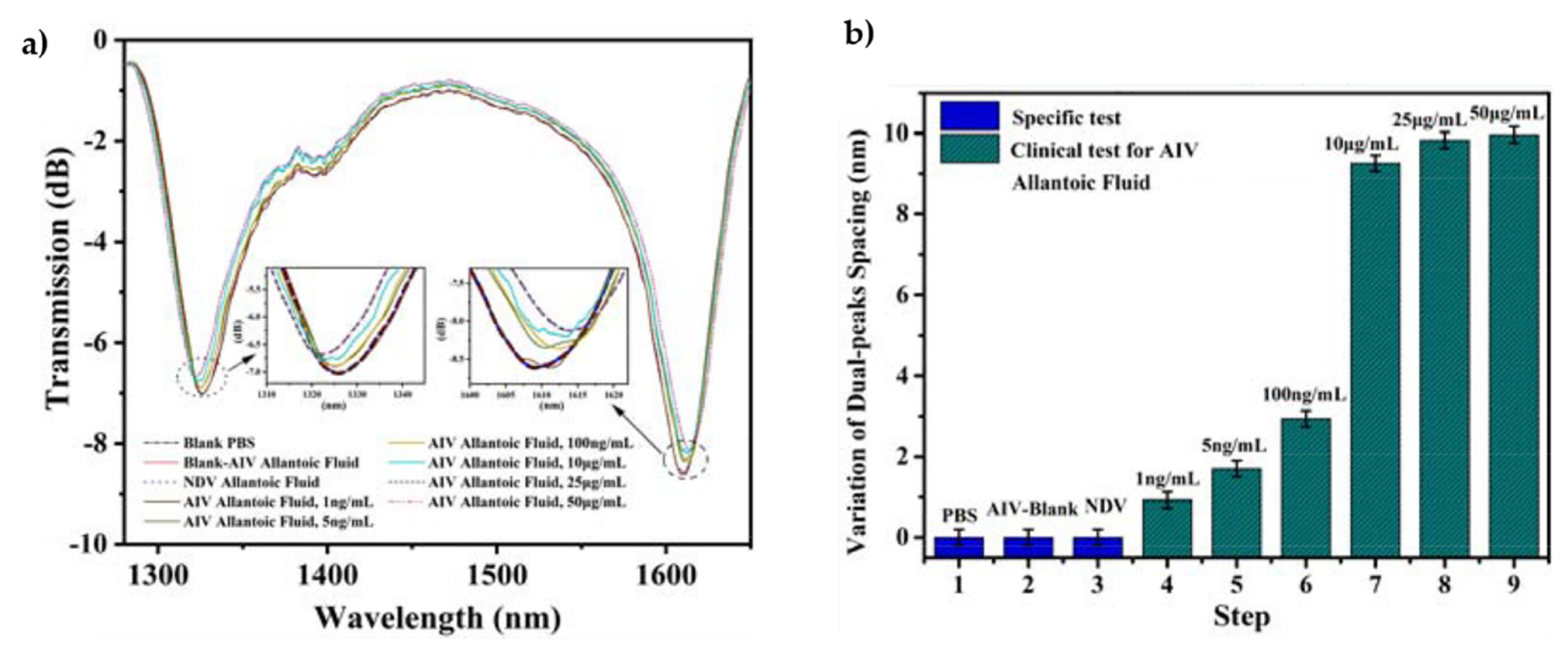
- Luo, B.; Liu, Z.; Wang, X.; Shi, S.; Zhong, N.; Ma, P.; Wu, S.; Wu, D.; Zhao, M.; Liang, W. Dual-peak long period fiber grating coated with graphene oxide for label-free and specific assays of H5N1 virus. J. Biophotonics 2021, 14, 1–10. [Google Scholar] [CrossRef]
- Peltomaa, R.; Glahn-Martínez, B.; Benito-Peña, E.; Moreno-Bondi, M. Optical Biosensors for Label-Free Detection of Small Molecules. Sensors 2018, 18, 4126. [Google Scholar] [CrossRef] [PubMed] [Green Version]
- Bintsis, T. Foodborne pathogens. Microbiology 2017, 3, 529–563. [Google Scholar] [CrossRef] [PubMed]
- Taniguchi, M.; Saito, H.; Mitsubayashi, K. Repetitive immunosensor with a fiber-optic device and antibody-coated magnetic beads for semi-continuous monitoring of Escherichia coli O157:H7. Sensors 2017, 17, 2145. [Google Scholar] [CrossRef] [Green Version]
- Kaushik, S.; Tiwari, U.; Nilima, P.S.; Das, B.; Sinha, R.K. Label-free detection of Escherichia coli bacteria by cascaded chirped long period gratings immunosensor. Rev. Sci. Instrum. 2019, 90, 9. [Google Scholar] [CrossRef] [PubMed]
- Chen, L.; Leng, Y.K.; Liu, B.; Liu, J.; Wan, S.P.; Wu, T.; Yuan, J.; Shao, L.; Gu, G.; Fu, Y.Q.; et al. Ultrahigh-sensitivity label-free optical fiber biosensor based on a tapered singlemode- no core-singlemode coupler for Staphylococcus aureus detection. Sens. Actuators B Chem. 2020, 320, 7. [Google Scholar] [CrossRef]
- Ribaut, C.; Loyez, M.; Larrieu, J.C.; Chevineau, S.; Lambert, P.; Remmelink, M.; Wattiez, R.; Caucheteur, C. Cancer biomarker sensing using packaged plasmonic optical fiber gratings: Towards in vivo diagnosis. Biosens. Bioelectron. 2017, 92, 449–456. [Google Scholar] [CrossRef]
- Uo, B.I.L.; Ang, Y.A.W.; Uafeng, H.L.U.; Hengxi, S.W.U.; Ouming, Y.L.U.; Hi, S.H.S.; Ingchen, L.L.I.; Hanghai, S.; Iang, J.; Hao, M.I.Z. Label-free and specific detection of soluble programmed death ligand-1 using a localized surface plasmon resonance biosensor based on excessively tilted fiber gratings. Biomed. Opt. Express 2019, 10, 5136–5148. [Google Scholar]
- Zhou, W.; Li, K.; Wei, Y.; Hao, P.; Chi, M.; Liu, Y.; Wu, Y. Ultrasensitive label-free optical microfiber coupler biosensor for detection of cardiac troponin I based on interference turning point effect. Biosens. Bioelectron. 2018, 106, 99–104. [Google Scholar] [CrossRef]
- Luo, B.; Wu, S.; Zhang, Z.; Zou, W.; Shi, S.; Zhao, M.; Zhong, N.; Liu, Y.; Zou, X.; Wang, L.; et al. Human heart failure biomarker immunosensor based on excessively tilted fiber gratings. Biomed. Opt. Express 2017, 8, 57. [Google Scholar] [CrossRef] [PubMed] [Green Version]
- Pinto, V.; Sousa, P.; Catarino, S.O.; Correia-Neves, M.; Minas, G. Microfluidic immunosensor for rapid and highly-sensitive salivary cortisol quantification. Biosens. Bioelectron. 2017, 90, 308–313. [Google Scholar] [CrossRef] [Green Version]
- Holsboer, F.; Ising, M. Stress Hormone Regulation: Biological Role and Translation into Therapy. Annu. Rev. Psychol. 2010, 61, 81–109. [Google Scholar] [CrossRef] [PubMed]
- Usha, S.P.; Shrivastav, A.M.; Gupta, B.D. A contemporary approach for design and characterization of fiber-optic-cortisol sensor tailoring LMR and ZnO/PPY molecularly imprinted film. Biosens. Bioelectron. 2017, 87, 178–186. [Google Scholar] [CrossRef]
- Ogawa, K.; Ito, F.; Nagae, M.; Nishimura, T.; Yamaguchi, M.; Ishimatsu, A. Effects of Acid Stress on Reproductive Functions in Immature Carp, Cyprinus Carpio. Water Air Soil Pollut. 2001, 130, 887–892. [Google Scholar] [CrossRef]
- European Commission. Sustainable Development. Available online: https://ec.europa.eu/environment/eussd/ (accessed on 29 August 2021).
- Sharma, A.K.; Kaur, B.; Marques, C. Simulation and analysis of 2D material/metal carbide based fiber optic SPR probe for ultrasensitive cortisol detection. Optik 2020, 218, 8. [Google Scholar] [CrossRef]
- Nie, R.; Huang, J.; Xu, X.; Yang, L. A portable pencil-like immunosensor for point-of-care testing of inflammatory biomarkers. Anal. Bioanal. Chem. 2020, 412, 3231–3239. [Google Scholar] [CrossRef]
- Liu, G.; Zhang, K.; Nadort, A.; Hutchinson, M.R.; Goldys, E.M. Sensitive Cytokine Assay Based on Optical Fiber Allowing Localized and Spatially Resolved Detection of Interleukin-6. ACS Sens. 2017, 2, 218–226. [Google Scholar] [CrossRef] [Green Version]
- Lamarca, R.S.; Franco, D.F.; Nalin, M.; De Lima Gomes, P.C.F.; Messaddeq, Y. Label-Free Ultrasensitive and Environment-Friendly Immunosensor Based on a Silica Optical Fiber for the Determination of Ciprofloxacin in Wastewater Samples. Anal. Chem. 2020, 92, 14415–14422. [Google Scholar] [CrossRef]
- Liu, J.; Xing, Y.; Zhou, X.; Chen, G.Y.; Shi, H. Light-sheet skew rays enhanced U-shaped fiber-optic fluorescent immunosensor for Microcystin-LR. Biosens. Bioelectron. 2021, 176, 7. [Google Scholar] [CrossRef]
- Yang, R.; Song, D.; Fang, S.; Liu, Y.; Zhou, X.; Long, F.; Zhu, A. Development of novel portable and reusable fiber optical chemiluminescent biosensor and its application for sensitive detection of microcystin-LR. Biosens. Bioelectron. 2018, 121, 27–33. [Google Scholar] [CrossRef]
- Gao, R.; Lu, D.F.; Zhang, M.Y.; Qi, Z.M. Optofluidic Immunosensor Based on Resonant Wavelength Shift of a Hollow Core Fiber for Ultratrace Detection of Carcinogenic Benzo[a]pyrene. ACS Photonics 2018, 5, 1273–1280. [Google Scholar] [CrossRef]
- Myndrul, V.; Viter, R.; Savchuk, M.; Koval, M.; Starodub, N.; Silamiķelis, V.; Smyntyna, V.; Ramanavicius, A.; Iatsunskyi, I. Gold coated porous silicon nanocomposite as a substrate for photoluminescence-based immunosensor suitable for the determination of Aflatoxin B1. Talanta 2017, 175, 297–304. [Google Scholar] [CrossRef] [PubMed]
- Wang, Y.; Luo, B.; Shi, S.; Wu, D.; Lv, Q.; Liu, Z.; Nie, Q. Immunosensor Based On Cladding-etched Excessively Tilted Fiber Grating Coated With Graphene Oxide. In Proceedings of the 2019 18th International Conference on Optical Communications and Networks (ICOCN), Huangshan, China, 5–8 August 2019; p. 3. [Google Scholar]
- Zhang, K.; Baratta, M.V.; Liu, G.; Frank, M.G.; Leslie, N.R.; Watkins, L.R.; Maier, S.F.; Hutchinson, M.R.; Goldys, E.M. A novel platform for in vivo detection of cytokine release within discrete brain regions. Brain. Behav. Immun. 2018, 71, 18–22. [Google Scholar] [CrossRef] [PubMed]
- Liu, L.; Zhou, X.; Lu, Y.; Shan, D.; Xu, B.; He, M.; Shi, H.; Qian, Y. Facile screening of potential xenoestrogens by an estrogen receptor-based reusable optical biosensor. Biosens. Bioelectron. 2017, 97, 16–20. [Google Scholar] [CrossRef] [PubMed]
- Cano-Velázquez, M.S.; López-Marín, L.M.; Hernández-Cordero, J. Fiber optic interferometric immunosensor based on polydimethilsiloxane (PDMS) and bioactive lipids. Biomed. Opt. Express 2020, 11, 1316. [Google Scholar] [CrossRef]
- Tabassum, R.; Kant, R. Cascaded wavelength multiplexed refractive index sensors in optical fibers based on surface plasmon resonances. J. Appl. Phys. 2020, 128, 15. [Google Scholar] [CrossRef]


| Figures-of-Merit | Definition |
|---|---|
| Linear concentration range | Detection range within the sensor has a linear response |
| Sensitivity (S) | Ratio between the change in output signal in response to variations of the concentration of the measured analyte |
| LOB | Highest apparent analyte concentration expected to be found when replicates of blank samples are tested (no analyte in the samples) |
| LOD | Lowest analyte concentration, which is not related to noise, detectable by the sensor with acceptable degree of certainty |
| LOQ | Lowest analyte concentration that can be quantified with an acceptable degree of certainty |
| Specificity | Ability to discern the response of the analyte of interest from every other interferent |
| Accuracy | Proximity between the sensor output value and the actual value of the measured analyte |
| Reproducibility | Capability to obtain a similar response over several repetitions using the same sensor and analyte when performing under different conditions |
| Repeatability | Capability to obtain a similar response over several repetitions using the same sensor and analyte when performing under the same conditions |
| Sensor Structure | Analyte | Surface Coating | Detection Principle | Sensitivity | LOD | Linear Range | Ref. |
|---|---|---|---|---|---|---|---|
| Bacteria | |||||||
| FBG | E. coli | - | Strain | - | - | - | [101] |
| POF | E. coli O157:H7 | - | Fluorescence | - | 1.0 × 10³ cells·mL−1 | 1.0 × 10³–1.0 × 10⁷ cells·mL−1 | [122] |
| Etched POF | E. coli | Au and MoS2 | SPR | 2.9 nm/1000 CFU·mL−1 (3135 nm·RIU−1) | 94 CFU·mL−1 | 1000–8000 CFU·mL−1 | [114] |
| CLPG | E. coli | - | RI | - | 7 CFU·mL−1 | 10–60 CFU·mL−1 | [123] |
| SMS | Salmonella Typhimurium | - | RI | 275.86 nm·RIU−1 | 247 CFU·mL−1 | 500–5000 CFU·mL−1 | [118] |
| Tapered SNSFC | S. aureus | - | RI | - | 3.1 CFU·mL−1 | 7 × 101–7 × 10⁴ CFU·mL−1 | [124] |
| Virus | |||||||
| Tapered SMF | DENV E proteins | - | RI | 5.02 nm·nM−1 | 1 pM | - | [14] |
| LPG | H5N1 | GO | RI | - | 1.05 ng·mL−1 | 1 ng·mL−1–25 μg·mL−1 | [119] |
| U-shape POF | CHIKV-nsP3 | - | RI | 0.1043 A530 nm·(log(CnsP3))−1 | 0.52 ng·mL−1 | 1–104 ng·mL−1 | [99] |
| Ex-TFBG | NDV | Au nanospheres | LSPR | - | 25 pg·mL−1 | 0–200 pg·mL−1 | [13] |
| LPG | Norovirus VLP | - | RI | - | 1 ng·mL−1 | - | [104] |
| Cancer Biomarkers | |||||||
| Unclad end-face reflected | HER2 | Au | SPR | 0.17 nm·nM−1 | 9.3 ng·mL−1 | - | [44] |
| Taper interferometer cascaded with FBG | HER2 | - | RI | - | 2 ng·mL−1 | - | [93] |
| TFBG | CK17 | Au | SPR | - | 0.1 ng·mL−1 (gel matrix) | - | [125] |
| PCF | AFP | - | Fluorescence | - | 0.1 ng·mL−1 | 0.1–150 ng·mL−1 | [107] |
| ex-TFBG | sPD-L1 | Au nanoshells | LSPR | - | 1 pg·mL−1 (buffer) 5 pg·mL−1 (FBS) | - | [126] |
| Cardiac Biomarkers | |||||||
| PS-mFBG | cTnI | - | RI | - | 0.03 ng·mL−1 | 0.1–10 ng·mL−1 | [109] |
| OMC | - | RI | - | 2 fg·mL−1 | 2–10 fg·mL−1 | [127] | |
| Ex-TFBG | NT-proBNP | - | RI | 45.967 pm.(ng·mL−1)−1 | 0.5 ng·mL−1 | 0.0–1.0 ng·mL−1 | [128] |
| Stress Biomarkers | |||||||
| Unclad POF | Cortisol | Ag and Ti3C2O2 | SPR | - | 15.7 fg·mL−1 | 0.36–4.50 ng·mL−1 | [134] |
| Unclad POF | Au/Pd | SPR | 3.56 ± 0.20 nm·(log(ng·mL−1))−1 | 1 pg·mL−1 | 0.005–10 ng·mL−1 | [84] | |
| TFBG | Au | SPR | 0.275 ± 0.028 nm·(ng·mL−1)−1 | - | 0.1–10 ng·mL−1 | [92] | |
| Inflammatory Biomarkers | |||||||
| SOF | IL-6 | Au NPs | Fluorescence | - | 1 pg·mL−1 | 1–400 pg·mL−1 | [136] |
| Unclad End-face reflected | CRP | Au | SPR | 1.17 nm·(log(µg·mL−1))−1 | - | 0.01–20 µg·mL−1 | [30] |
| PPS (End-face reflected) | IL-6 | - | Chemiluminescence | - | 1.05 pg·mL−1 | 5–10,000 pg·mL−1 | [135] |
| PCT | 10.64 pg·mL−1 | 0.05–200 ng·mL−1 | |||||
| CRP | 29.40 ng·mL−1 | 0.1–80 μg·mL−1 | |||||
| Environmental | |||||||
| End-face reflected | PAEs | - | Fluorescence | - | 19–51 ng·L−1 | 0.01–100 µg·L−1 | [103] |
| D-shape | NAPHTA | Au | SPR | - | 0.76 ng·mL−1 | - | [56] |
| U-shape | MC-LR | - | RI Fluorescence | - | 0.46 µg·L−1 | 0.84–6.50 µg·L−1 | [138] |
| SOF | - | Chemiluminescence | - | 0.03 µg·L−1 | 0.23–190 µg·L−1 | [139] | |
| U-shape | CIP | - | RI | - | 3.30 × 10⁻³ ng·L−1 | 0.01–10,000 ng·L−1 | [137] |
| Unclad | MA | Au NPs | LSPR | - | 0.16 ng·mL−1 | 1–1000 ng·mL−1 | [110] |
| Hollow-core fiber | B[a]P | - | RI | 23 pm·pM−1 | 1.65 pM | - | [140] |
Publisher’s Note: MDPI stays neutral with regard to jurisdictional claims in published maps and institutional affiliations. |
© 2021 by the authors. Licensee MDPI, Basel, Switzerland. This article is an open access article distributed under the terms and conditions of the Creative Commons Attribution (CC BY) license (https://creativecommons.org/licenses/by/4.0/).
Share and Cite
Soares, M.S.; Vidal, M.; Santos, N.F.; Costa, F.M.; Marques, C.; Pereira, S.O.; Leitão, C. Immunosensing Based on Optical Fiber Technology: Recent Advances. Biosensors 2021, 11, 305. https://doi.org/10.3390/bios11090305
Soares MS, Vidal M, Santos NF, Costa FM, Marques C, Pereira SO, Leitão C. Immunosensing Based on Optical Fiber Technology: Recent Advances. Biosensors. 2021; 11(9):305. https://doi.org/10.3390/bios11090305
Chicago/Turabian StyleSoares, Maria Simone, Miguel Vidal, Nuno F. Santos, Florinda M. Costa, Carlos Marques, Sónia O. Pereira, and Cátia Leitão. 2021. "Immunosensing Based on Optical Fiber Technology: Recent Advances" Biosensors 11, no. 9: 305. https://doi.org/10.3390/bios11090305