
Removal of Methylene Blue and Congo Red Using a Chitosan–Graphene Oxide-Electrosprayed Functionalized Polymeric Nanofiber Membrane
 , and
, and
Abstract
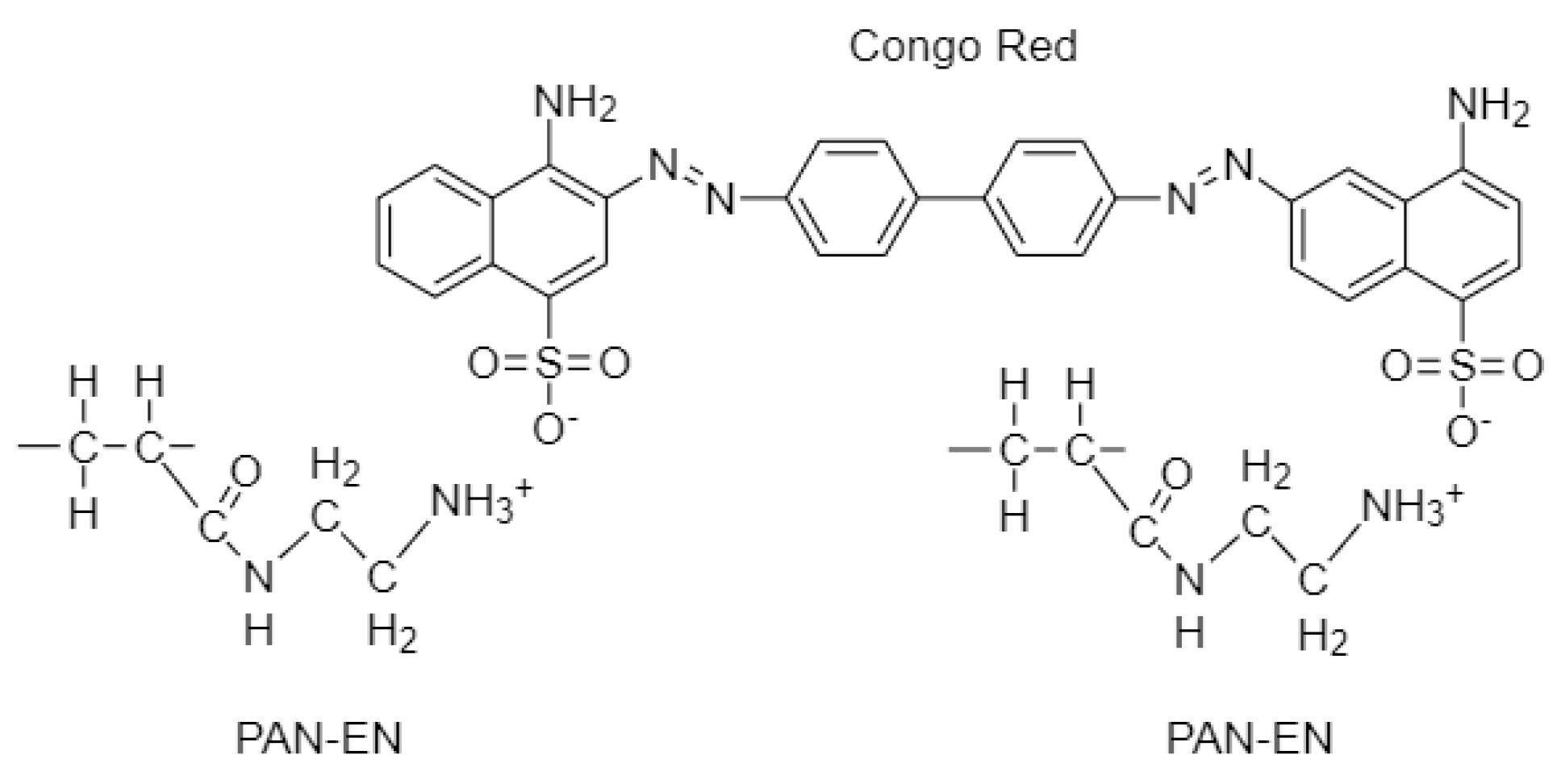
:1. Introduction
2. Materials and Methods
2.1. Materials
2.2. Extraction of Chitin and Deacetylation to Chitosan
2.3. Synthesis of GO
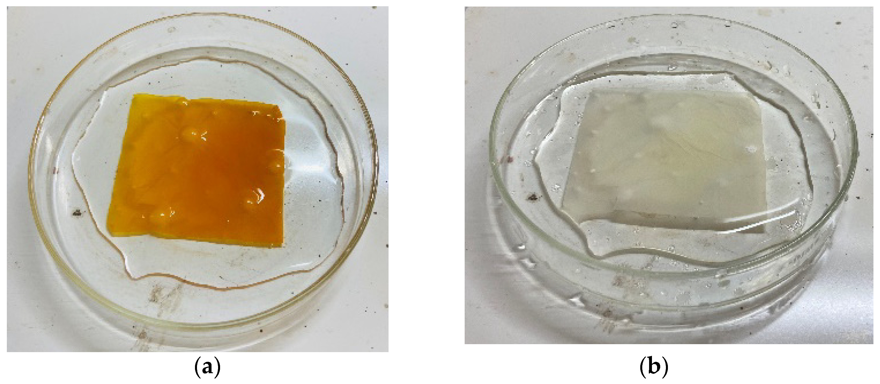
2.4. Preparation of Chitosan–Graphene Oxide Solution
2.5. Optimization of Electrospinning Parameters
2.6. Fabrication of Polyacrylonitrile-Electrospun Membrane
2.7. Surface Functionalization of Electrospun PAN Membrane
2.8. Preparation of Ch–GO-Electrosprayed PAN–EDA Membrane
2.9. Characterization
2.10. Adsorption Study of CS–GO Composite
2.11. Adsorption Isotherm Study of CS–GO Composite
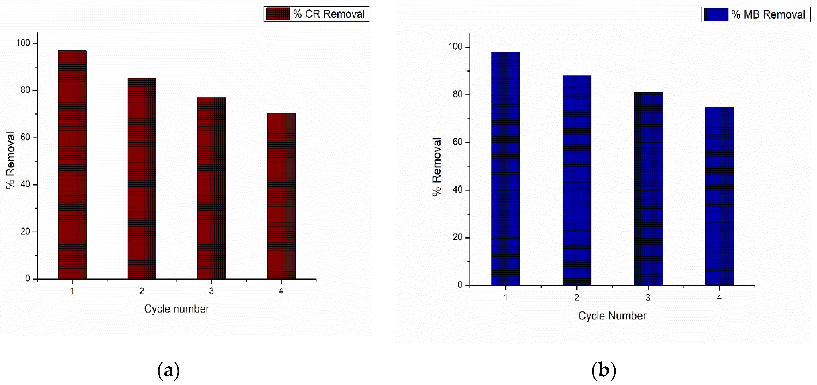
2.12. Reusability Study
3. Results and Discussion
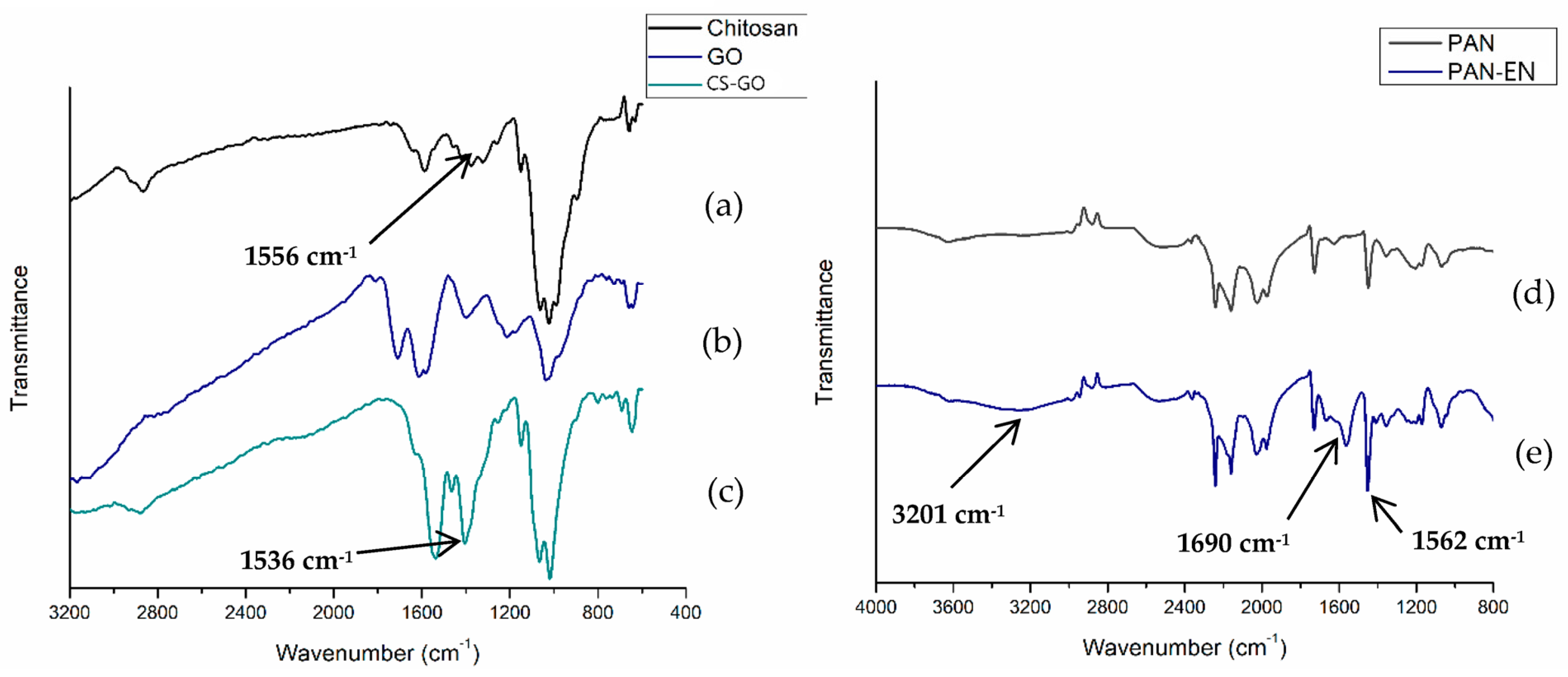
3.1. FT-IR Analysis
3.2. Optimization of Electrospinning Parameters
3.3. SEM Results
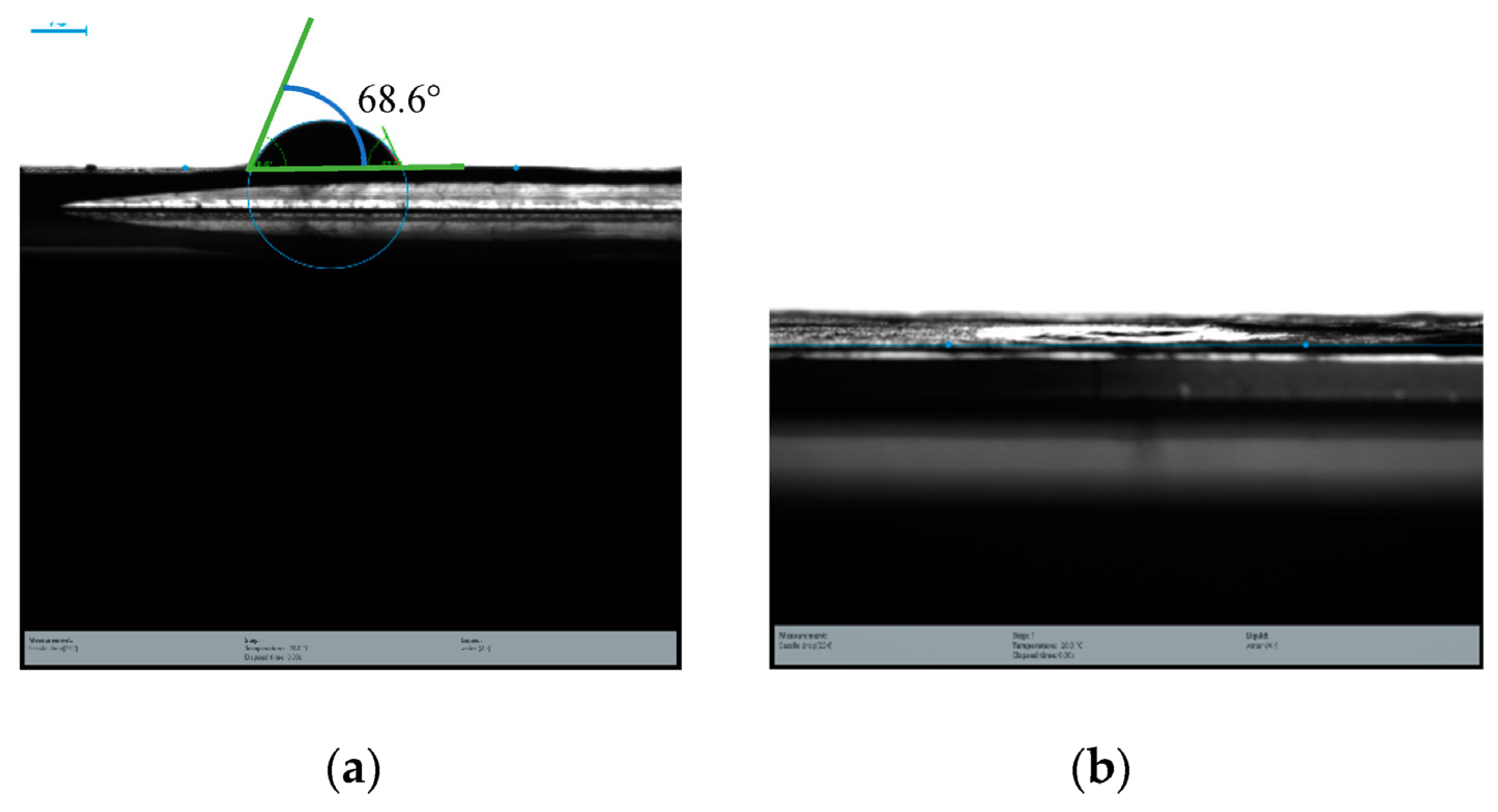
3.4. Contact Angle Measurements
3.5. Adsorption Study
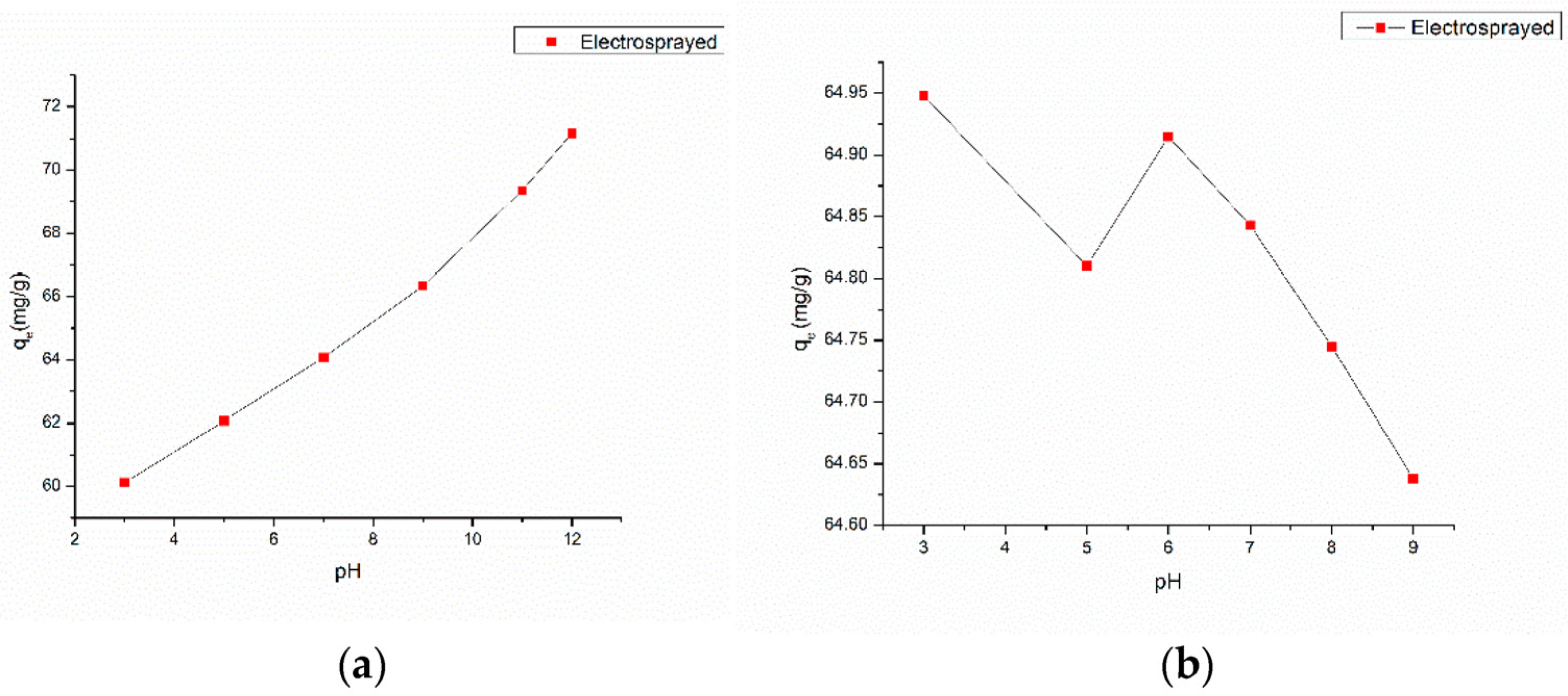
3.5.1. Effect of Solution pH on Adsorption
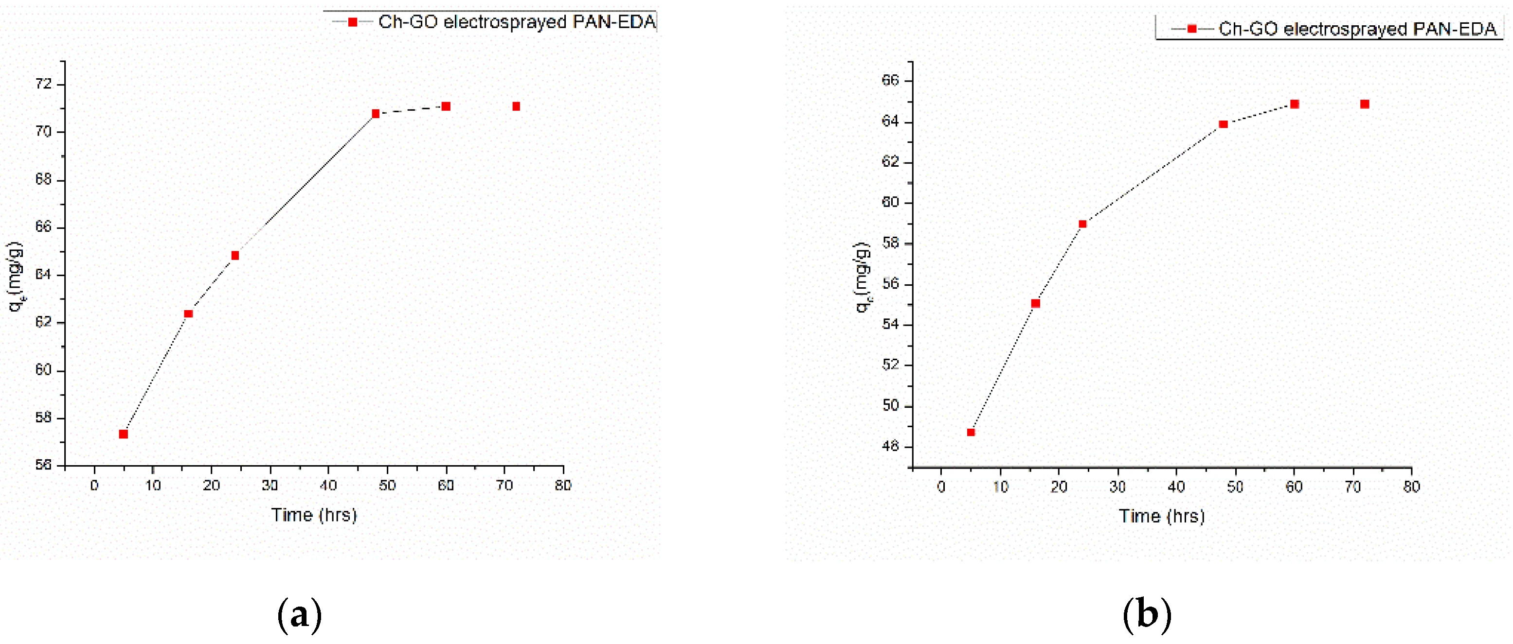
3.5.2. Effect of Contact Time
3.6. Adsorption Isotherm

| Absorbent | Dye Removed | Adsorption Capacity (mg/g) | Sources |
|---|---|---|---|
| Carbon nanotubes | MB | 46.2 | [64] |
| Graphene | MB | 153.9 | [65] |
| Magnetic graphene oxide/β-cyclodextrin | MB | 93.97 | [66] |
| SrAl2O3.Bi3+/graphene | MB | 42.92 | [75] |
| Graphene oxide–cyclodextrin–chitosan–ferric oxide | MB | 84 | [39] |
| Graphene oxide–chitosan–ferric oxide | MB | 95 | [38] |
| Graphene oxide–ferric oxide | MB | 167 | [76] |
| Graphene oxide/cobalt oxide nanocomposite | MB | 40 | [77] |
| Hydrogels loaded with magnetic reduced graphene oxide | MB | 119 | [78] |
| Raw chitosan | MB | 11 | [30] |
| Powdered graphene oxide | MB | 243 | [33] |
| Polyacrylonitrile nanofibers | MB | 42.67 | [13] |
| Oxime-grafted polyacrylonitrile | MB | 102.15 | [73] |
| Zinc-augmented polyacrylonitrile nanofibers | CR | 25.64 | [79] |
| PET fibers grafted with 4-VP | CR | 17.3 | [80] |
| Functionalized polyvinyl chloride–graphene-polyaniline fibers | CR | 40.0 | [81] |
| Zinc oxide/Tin oxide porous nanofibers | CR | 90.8 | [82] |
| Silicon dioxide–bohemite core/sheath fibers | CR | 24.3 | [83] |
| Chitosan hydrobeads | CR | 92.59 | [84] |
| Commercial activated carbon | CR | 66.67 | [85] |
| Acticated carbon loaded with palladium nanoparticles | CR | 76.9 | [86] |
| Acticated carbon loaded with gold nanoparticles | CR | 66.7 | [86] |
| Polyacrylonitrile–ethylene diamnine-functionalized membrane | CR | 130 | [29] |
| Chitosan–graphene oxide-dipcoated PAN–EDA nanocomposite | MB | 201 | [87] |
| Chitosan–graphene oxide-dipcoated PAN–EDA nanocomposite | CR | 152 | [87] |
| CS–GO-electrosprayed PAN–EN functionalized membrane | MB | 219.3 | Present work |
| CS–GO-electrosprayed PAN–EN functionalized membrane | CR | 151.745 | Present work |
3.7. Reusability Study
4. Conclusions
5. Future Perspectives
Author Contributions
Funding
Data Availability Statement
Conflicts of Interest
References
- Raval, N.P.; Shah, P.U.; Shah, N.K. Adsorptive amputation of hazardous azo dye Congo red from wastewater: A critical review. Environ. Sci. Pollut. Res. 2016, 23, 14810–14853. [Google Scholar] [CrossRef] [PubMed]
- Gharbani, P.; Tabatabaii, S.M.; Mehrizad, A. Removal of Congo red from textile wastewater by ozonation. Int. J. Environ. Sci. Technol. 2008, 5, 495–500. [Google Scholar] [CrossRef] [Green Version]
- SLin, H.; Chen, M.L. Treatment of textile wastewater by-chemical methods for reuse. Water Res. 1997, 31, 868–876. [Google Scholar] [CrossRef]
- Harrelkas, F.; Azizi, A.; Yaacoubi, A.; Benhammou, A.; Pons, M.N. Treatment of textile dye effluents using coagulation-flocculation coupled with membrane processes or adsorption on powdered activated carbon. Desalination 2009, 235, 330–339. [Google Scholar] [CrossRef]
- Ayodhya, D.; Veerabhadram, G. A review on recent advances in photodegradation of dyes using doped and heterojunction based semiconductor metal sulfide nanostructures for environmental protection. Mater. Today Energy 2018, 9, 83–113. [Google Scholar] [CrossRef]
- Varjani, S.; Rakholiya, P.; Ng, H.Y.; You, S.; Teixeira, J.A. Microbial degradation of dyes: An overview. Bioresour. Technol. 2020, 314, 123728. [Google Scholar] [CrossRef]
- Yagub, M.T.; Sen, T.K.; Afroze, S.; Ang, H.M. Dye and its removal from aqueous solution by adsorption: A review. Adv. Colloid Interface Sci. 2014, 209, 172–184. [Google Scholar] [CrossRef] [PubMed]
- Tripathi, N. Cationic and anionic dye adsorption by agricultural solid wastes: A comprehensive review by. IOSR J. Appl. Chem. 2013, 5, 91–108. [Google Scholar] [CrossRef]
- Kausar, A.; Iqbal, M.; Javed, A.; Aftab, K.; Nazli, Z.-H.; Bhatti, H.N.; Nouren, S. Dyes adsorption using clay and modified clay: A review. J. Mol. Liq. 2018, 256, 395–407. [Google Scholar] [CrossRef]
- Fito, J.; Abrham, S.; Angassa, K. Adsorption of Methylene Blue from Textile Industrial Wastewater onto Activated Carbon of Parthenium hysterophorus. Int. J. Environ. Res. 2020, 14, 501–511. [Google Scholar] [CrossRef]
- Yusop, M.F.M.; Ahmad, M.A.; Rosli, N.A.; Manaf, M.E.A. Adsorption of cationic methylene blue dye using microwave-assisted activated carbon derived from acacia wood: Optimization and batch studies. Arab. J. Chem. 2021, 14, 103122. [Google Scholar] [CrossRef]
- Ponnusami, V.; Madhuram, R.; Krithika, V.; Srivastava, S.N. Effects of process variables on kinetics of methylene blue sorption onto untreated guava (Psidium guajava) leaf powder: Statistical analysis. Chem. Eng. J. 2008, 140, 609–613. [Google Scholar] [CrossRef]
- Rafatullah, M.; Sulaiman, O.; Hashim, R.; Ahmad, A. Adsorption of methylene blue on low-cost adsorbents: A review. J. Hazard. Mater. 2010, 177, 70–80. [Google Scholar] [CrossRef] [PubMed]
- Kushwaha, A.K.; Gupta, N.; Chattopadhyaya, M.C. Removal of cationic methylene blue and malachite green dyes from aqueous solution by waste materials of Daucus carota. J. Saudi Chem. Soc. 2014, 18, 200–207. [Google Scholar] [CrossRef]
- Ayed, L.; Hkiri, N.; Hamdi, M. Congo Red Decolorization and Detoxification by Aspergillus niger: Removal Mechanisms and Dye Degradation Pathway Nedra Asses. BioMed Res. Int. 2018, 2018, 3049686. [Google Scholar]
- Mohammed, W.; Alabdraba, S.; Burhan, M.; Albayati, A. Biodegradation of Azo Dyes a Review Biodegradation of Azo Dyes—A Review. Int. J. Environ. Eng. Nat. Resour. 2014, 1, no. 4, 179–189. [Google Scholar]
- Hamad, M.T.M.H.; Saied, M.S.S. Kinetic studies of Congo red dye adsorption by immobilized Aspergillus niger on alginate. Appl. Water Sci. 2021, 11, 1–12. [Google Scholar] [CrossRef]
- Sinha, S.; Behera, S.S.; Das, S.; Basu, A.; Mohapatra, R.K.; Murmu, B.M.; Dhal, N.K.; Tripathy, S.K.; Parhi, P.K. Removal of Congo Red dye from aqueous solution using Amberlite IRA-400 in batch and fixed bed reactors. Chem. Eng. Commun. 2018, 205, 432–444. [Google Scholar] [CrossRef]
- Ray, S.S.; Chen, S.S.; Li, C.W.; Nguyen, N.C.; Nguyen, H.T. A comprehensive review: Electrospinning technique for fabrication and surface modification of membranes for water treatment application. RSC Adv. 2016, 6, 85495–85514. [Google Scholar] [CrossRef]
- Ma, H.; Hsaiao, B.S. Electrospun nanofibrous membranes for desalination. In Current Trends and Future Developmrnts on (Bio-) Membranes: Membrane Desalination Systems: The Next Generation; Elsevier: Amsterdam, The Netherlands, 2018; pp. 81–104. [Google Scholar]
- Persano, L.; Camposeo, A.; Tekmen, C.; Pisignano, D. Industrial Upscaling of Electrospinning and Applications of Polymer Nanofibers: A Review. Macromol. Mater. Eng. 2013, 298, 504–520. [Google Scholar] [CrossRef]
- Thamer, B.M.; Aldalbahi, A.; Moydeen, A.M.; Rahaman, M.; El-Newehy, M.H. Modified electrospun polymeric nanofibers and their nanocomposites as nanoadsorbents for toxic dye removal from contaminated waters: A review. Polymers 2021, 23, 20. [Google Scholar] [CrossRef] [PubMed]
- Almasian, A.; Fard, G.C.; Gashti, M.P.; Mirjalili, M.; Mokhtari, Z. Shourijeh Surface modification of electrospun PAN nanofibers by amine compounds for adsorption of anionic dyes. Desalin. Water Treat. 2016, 57, 10333–10348. [Google Scholar] [CrossRef]
- Elkady, M.F.; El-Aassar, M.R.; Hassan, H.S. Adsorption profile of basic dye onto novel fabricated carboxylated functionalized co-polymer nanofibers. Polymers 2016, 8, 177. [Google Scholar] [CrossRef] [PubMed] [Green Version]
- Ren, J.; Yan, C.; Liu, Q.; Yang, Q.; Lu, G.; Song, Y.; Li, Y. Preparation of amidoxime-modified polyacrylonitrile nanofibrous adsorbents for the extraction of copper(II) and lead(II) ions and dye from aqueous media. J. Appl. Polym. Sci. 2018, 135, 1–9. [Google Scholar] [CrossRef]
- Shoushtari, A.M.; Zargaran, M.; Abdouss, M. Preparation and characterization of high efficiency ion-exchange crosslinked acrylic fibers. J. Appl. Polym. Sci. 2006, 101, 2202–2209. [Google Scholar] [CrossRef]
- Tahaei, P.; Abdouss, M.; Edrissi, M.; Shoushtari, A.M.; Zargaran, M. Preparation of chelating fibrous polymer by different diamines and study on their physical and chemical properties. Materwiss. Werksttech. 2008, 39, 839–844. [Google Scholar] [CrossRef]
- Mahmoodi, N.M.; Mokhtari-Shourijeh, Z. Preparation of aminated nanoporous nanofiber by solvent casting/porogen leaching technique and dye adsorption modeling. J. Taiwan Inst. Chem. Eng. 2016, 65, 378–389. [Google Scholar] [CrossRef]
- Patel, S.; Hota, G. Synthesis of novel surface functionalized electrospun PAN nanofibers matrix for efficient adsorption of anionic CR dye from water. J. Environ. Chem. Eng. 2018, 6, 5301–5310. [Google Scholar] [CrossRef]
- Moosa, A.; Ridha, A.; Moosa, A.A.; Ridha, A.M.; Kadhim, N.A. Use of Biocomposite Adsorbents for the Removal of Methylene Blue Dye from Aqueous Solution Use of Biocomposite Adsorbents for the Removal of Methylene Blue Dye from Aqueous Solution. Am. J. Mater. Sci. 2016, 6, 135–146. [Google Scholar] [CrossRef]
- Ionannou, Z.; Karasawidis, C.; Dimirkou, A.; Antoniadis, V. Adsorption of méthylène blue and methyl red dyes from aqueous solutions onto modified zeolites. Water Sci. Technol. 2013, 67, 1129–1136. [Google Scholar] [CrossRef]
- Szlachta, M.; Wójtowicz, P. Adsorption of methylene blue and Congo red from aqueous solution by activated carbon and carbon nanotubes. Water Sci. Technol. 2013, 68, 2240–2248. [Google Scholar] [CrossRef] [PubMed]
- Li, Y.; Du, Q.; Liu, T.; Peng, X.; Wang, J.; Sun, J.; Wang, Y.; Wu, S.; Wang, Z.; Xia, Y.; et al. Comparative study of methylene blue dye adsorption onto activated carbon, graphene oxide, and carbon nanotubes. Chem. Eng. Res. Des. 2013, 91, 361–368. [Google Scholar] [CrossRef]
- Abbas, A.; Abussaud, B.A.; Ihsanullah; Al-Baghli, N.A.H.; Khraisheh, M.; Atieh, M.A. Benzene removal by iron oxide nanoparticles decorated carbon nanotubes. J. Nanomater. 2016, 2016, 5654129. [Google Scholar] [CrossRef] [Green Version]
- Park, S.; Lee, K.-S.; Bozoklu, G.; Cai, W.; Nguyen, S.T.; Ruoff, R.S. Graphene Oxide Papers Modified by Divalent Ions—Enhancing Mechanical Properties via Chemical Cross-Linking. ACS Nano 2008, 2, 572–578. [Google Scholar] [CrossRef]
- Shao, L.; Chang, X.; Zhang, Y.; Huang, Y.; Yao, Y.; Guo, Z. Graphene oxide cross-linked chitosan nanocomposite membrane. Appl. Surf. Sci. 2013, 280, 989–992. [Google Scholar] [CrossRef]
- Sabzevari, M.; Cree, D.E.; Wilson, L.D. Graphene Oxide−Chitosan Composite Material for Treatment of a Model Dye Effluent. ACS Omega 2018, 3, 13045–13054. [Google Scholar] [CrossRef] [PubMed] [Green Version]
- Yao, Y.; Miao, S.; Yu, S.; Ma, L.P.; Sun, H.; Wang, S. Fabrication of Fe3O4/SiO2 core/shell nanoparticles attached to graphene oxide and its use as an adsorbent. J. Colloid Interface Sci. 2012, 379, 20–26. [Google Scholar] [CrossRef] [PubMed]
- He, F.; Fan, J.; Ma, D.; Zhang, L.; Leung, C.; Chan, H.L. The attachment of Fe3O4 nanoparticles to graphene oxide by covalent bonding. Carbon N. Y. 2010, 48, 3139–3144. [Google Scholar] [CrossRef]
- Youe, W.J.; Lee, S.M.; Lee, S.S.; Lee, S.H.; Kim, Y.S. Characterization of carbon nanofiber mats produced from electrospun lignin-g-polyacrylonitrile copolymer. Int. J. Biol. Macromol. 2016, 82, 497–504. [Google Scholar] [CrossRef]
- Huang, J.; Deng, H.; Song, D.; Xu, H. Electrospun polystyrene/graphene nanofiber film as a novel adsorbent of thin film microextraction for extraction of aldehydes in human exhaled breath condensates. Anal. Chim. Acta 2015, 878, 102–108. [Google Scholar] [CrossRef]
- Lou, T.; Yan, X.; Wang, X. Chitosan coated polyacrylonitrile nanofibrous mat for dye adsorption. Int. J. Biol. Macromol. 2019, 135, 919–925. [Google Scholar] [CrossRef] [PubMed]
- Hossain, M.S.; Iqbal, A. Production and characterization of chitosan from shrimp waste. J. Bangladesh Agric. Univ. 2014, 12, 153–160. [Google Scholar] [CrossRef] [Green Version]
- Marcano, D.C.; Kosynkin, D.V.; Berlin, J.M.; Sinitskii, A.; Sun, Z.; Slesarev, A.; Alemany, L.B.; Lu, W.; Tour, J.M. Improved Synthesis ofGraphene Oxide. ACS Nano 2010, 4, 4806–4811. [Google Scholar] [CrossRef] [PubMed]
- Tissera, N.D.; Wijesena, R.N.; Perera, J.R.; De Silva, K.M.N.; Amaratunge, G.A.J. Applied Surface Science Hydrophobic cotton textile surfaces using an amphiphilic graphene oxide (GO) coating. Appl. Surf. Sci. 2015, 324, 455–463. [Google Scholar] [CrossRef]
- Liu, L.; Luo, X.B.; Ding, L.; Luo, S.L. Application of Nanotechnology in the Removal of Heavy Metal from Water; Elsevier Inc.: Amsterdam, The Netherlands, 2018. [Google Scholar] [CrossRef]
- Patel, S.; Hota, G. Adsorptive removal of malachite green dye by functionalized electrospun PAN nanofibers membrane. Fibers Polym. 2014, 15, 2272–2282. [Google Scholar] [CrossRef]
- Queiroz, M.F.; Rachel, K.; Melo, T.; Sabry, D.A.; Sassaki, G.L.; Alexandre, H.; Rocha, O. Does the Use of Chitosan Contribute to Oxalate Kidney Stone Formation? Mar. Drugs 2015, 13, 141–158. [Google Scholar] [CrossRef]
- Knidri, H.E.L.; Belaabed, R.; El, R.; Laajeb, A.; Addaou, A.; Lahsini, A. Physicochemical Characterization of Chitin and Chitosan Producted from Parapenaeus Longirostris Shrimp Shell Wastes. J. Mater. Environ. Sci. 2017, 8, 3648–3653. [Google Scholar]
- Kumari, S.; Kumar, P. Extraction and Characterization of Chitin and Chitosan from (Labeo rohit) Fish Scales. Procedia Mater. Sci. 2014, 6, 482–489. [Google Scholar] [CrossRef] [Green Version]
- Laaraibi, A.; Charhouf, I.; Bennamara, A.; Abourriche, A.; Berrada, M. Valorization of marine wastes in a preserving film based on chitosan for food applications. J. Mater. Environ. Sci. 2015, 6, 3511–3516. [Google Scholar]
- Nazri, S.; Liu, W.-W.; Khe, C.-S.; Hidayah, N.M.; Lee, A.P.Y. Cheun Synthesis, characterization and study of graphene oxide. AIP Conf. Proc. 2018, 2045, 020033. [Google Scholar]
- Çiplak, Z.; Yildiz, N.; Çalimli, A. Investigation of Graphene/Ag Nanocomposites Synthesis Parameters for Two Different Synthesis Methods. Fuller. Nanotub. Carbon Nanostruct. 2015, 23, 361–370. [Google Scholar] [CrossRef]
- Jenab, A.; Roghanian, R.; Ghorbani, N.; Ghaedi, K.; Emtiazi, G. The Efficacy of Electrospun PAN/Kefiran Nano fiber and Kefir in Mammalian Cell Culture: Promotion of PC12 Cell Growth, Anti-MCF7 Breast Cancer Cells Activities, and Cytokine Production of PBMC. Int. J. Nanomed. 2020, 15, 717–728. [Google Scholar] [CrossRef] [PubMed] [Green Version]
- Deitzel, J.; Kleinmeyer, J.; Harris, D.; Tan, N.C.B. The effect of processing variables on the morphology of electrospun nanofibers and textiles. Polymer 2001, 42, 261–272. [Google Scholar] [CrossRef]
- Ramakrishna, S.; Fujihara, K.; Teo, W.E.; Lim, T.C.; Ma, Z. An Introduction to Electrospinning and Nanofibers; World Science Publisher Co Pvt Ltd.: Singapore, 2005. [Google Scholar]
- Kriegel, C.; Kit, K.M.; McClements, D.J.; Weiss, J. Electrospinning of chitosan-poly(ethylene oxide) blend nanofibers in the presence of micellar surfactant solutions. Polymer 2009, 50, 189–200. [Google Scholar] [CrossRef]
- Haider, S.; Waheed, A.A.-M.; Bukhari, N.; Javid, M. Preparation of the Chitosan containing Nanofibers by Electrospinning Chitosan-Gelatin Complexes. Polym. Eng. Sci. 2010, 50, 1887–1893. [Google Scholar] [CrossRef]
- Huang, X.; Bu, H.; Jiang, G.; Zeng, M. International Journal of Biological Macromolecules Cross-linked succinyl chitosan as an adsorbent for the removal of Methylene Blue from aqueous solution. Int. J. Biol. Macromol. 2011, 49, 643–651. [Google Scholar] [CrossRef]
- Yang, S.; Chen, S.; Chang, Y.; Cao, A.; Liu, Y.; Wang, H. Journal of Colloid and Interface Science Removal of methylene blue from aqueous solution by graphene oxide. J. Colloid Interface Sci. 2011, 359, 24–29. [Google Scholar] [CrossRef]
- Kumar, R.; Ansari, M.O.; Parveen, N.; Barakat, M.A.; Cho, M.H. Simple route for the generation of differently functionalized PVC@graphene-polyaniline fiber bundles for the removal of Congo red from wastewater. RSC Adv. 2015, 5, 61486–61494. [Google Scholar] [CrossRef]
- Chem, J.; Process, E.; Nadjia, L.; Abdelkader, E.; Ahmed, B. Photodegradation study of Congo Red in Aqueous Solution using ZnO/UV-A: Effect of pH And Band Gap of other Semiconductor Groups. Chem. Eng. Process Technol. 2011, 2, 1–7. [Google Scholar] [CrossRef]
- Thangavel, K.; Rathinamoorthy, R. Recycling and Reuse of Textile Effluent Sludge. In Environmental Implications of Recycling and Recycled Products; no. August; Springer Science + Business Media Singapore: Singapore, 2015; pp. 978–981. [Google Scholar] [CrossRef]
- Yao, Y.; Xu, F.; Chen, M.; Xu, Z.; Zhu, Z. Adsorption behavior of methylene blue on carbon nanotubes. Bioresour. Technol. 2010, 101, 3040–3046. [Google Scholar] [CrossRef]
- Ersan, G.; Apul, O.G.; Perreault, F.; Karanfil, T. Adsorption of organic contaminants by graphene nanosheets: A review. Water Res. 2017, 126, 385–398. [Google Scholar] [CrossRef] [PubMed]
- Ma, Y.X.; Shao, W.J.; Sun, W.; Kou, Y.L.; Li, X.; Yang, H.P. One-step fabrication of β-cyclodextrin modified magnetic graphene oxide nanohybrids for adsorption of Pb (II), Cu (II) and methylene blue in aqueous solutions. Appl. Surf. Sci. 2018, 459, 544–553. [Google Scholar] [CrossRef]
- Domingues, J.T.; Orlando, R.M.; Sinisterra, R.D.; Pinzón-García, A.D.; Rodrigues, G.D. Polymer-bixin nanofibers: A promising environmentally friendly material for the removal of dyes from water. Sep. Purif. Technol. 2020, 248, 117118. [Google Scholar] [CrossRef]
- Huong, D.T.M.; Chai, W.S.; Show, P.L.; Lin, Y.L.; Chiu, C.Y.; Tsai, S.L.; Chang, Y.K. Removal of cationic dye waste by nanofiber membrane immobilized with waste proteins. Int. J. Biol. Macromol. 2020, 164, 3873–3884. [Google Scholar] [CrossRef]
- Bahalkeh, F.; Habibi Juybari, M.; Mehrabian, R.Z.; Ebadi, M. Removal of Brilliant Red dye (Brilliant Red E-4BA) from wastewater using novel Chitosan/SBA-15 nanofiber. Int. J. Biol. Macromol. 2020, 164, 818–825. [Google Scholar] [CrossRef] [PubMed]
- Mohammad, N.; Atassi, Y. Adsorption of methylene blue onto electrospun nanofibrous membranes of polylactic acid and polyacrylonitrile coated with chloride doped polyaniline. Sci. Rep. 2020, 10, 13412. [Google Scholar] [CrossRef] [PubMed]
- Qi, F.F.; Ma, T.Y.; Liu, Y.; Fan, Y.M.; Li, J.Q.; Yu, Y.; Ling, L. Chu 3D superhydrophilic polypyrrole nanofiber mat for highly efficient adsorption of anionic azo dyes. Microchem. J. 2020, 159, 105389. [Google Scholar] [CrossRef]
- Haider, S.; Binagag, F.F.; Haider, A.; Mahmood, A.; Shah, N.; Al-Masry, W.A.; Khan, S.U.-D.; Ramay, S.M. Adsorption kinetic and isotherm of methylene blue, safranin T and rhodamine B onto electrospun ethylenediamine-grafted-polyacrylonitrile nanofibers membrane. Desalination Water Treat. 2015, 55, 1609–1619. [Google Scholar] [CrossRef]
- Haider, S.; Binagag, F.F.; Haider, A.; Al-Masry, W.A. Electrospun oxime-grafted-polyacrylonitrile nanofiber membrane and its application to the adsorption of dyes. J. Polym. Res. 2014, 21, 1–13. [Google Scholar] [CrossRef]
- Omer, A.M.; Dey, R.; Eltaweil, A.S.; El-Monaem, E.M.A.; Ziora, Z.M. Insights into recent advances of chitosan-based adsorbents for sustainable removal of heavy metals and anions. Arab. J. Chem. 2022, 15, 103543. [Google Scholar] [CrossRef]
- Oliva, J.; Martinez, A.I.; Oliva, A.I.; Garcia, C.R.; Martinez-Luevanos, A.; Garcia-Lobato, M.; Ochoa-Valiente, R.; Berlanga, A. Flexible graphene composites for removal of methylene blue dye-contaminant from water. Appl. Surf. Sci. 2018, 436, 739–746. [Google Scholar] [CrossRef]
- Xie, G.; Xi, P.; Liu, H.; Chen, F.; Huang, L.; Shi, Y.; Hou, F.; Zeng, Z.; Shao, C.; Wang, J. A facile chemical method to produce superparamagnetic graphene oxide-Fe3O4 hybrid composite and its application in the removal of dyes from aqueous solution. J. Mater. Chem. 2012, 22, 1033–1039. [Google Scholar] [CrossRef]
- Pourzare, K.; Farhadi, S.; Mansourpanah, Y. Graphene oxide/Co3O4 nanocomposite: Synthesis, characterization, and its adsorption capacity for the removal of organic dye pollutants from water. Acta Chim. Slov. 2017, 64, 945–958. [Google Scholar] [CrossRef] [PubMed] [Green Version]
- Halouane, F.; Oz, Y.; Meziane, D.; Barras, A.; Juraszek, J.; Singh, S.K.; Kurungot, S.; Shaw, P.K.; Sanyal, R.; Boukherroub, R.; et al. Magnetic reduced graphene oxide loaded hydrogels: Highly versatile and efficient adsorbents for dyes and selective Cr(VI) ions removal. J. Colloid Interface Sci. 2017, 507, 360–369. [Google Scholar] [CrossRef] [PubMed]
- Chauhan, D.; Afreen, S.; Mishra, S.; Sankararamakrishnan, N. Synthesis, characterization and application of zinc augmented aminated PAN nanofibers towards decontamination of chemical and biological contaminants. J. Ind. Eng. Chem. 2017, 55, 50–64. [Google Scholar] [CrossRef]
- Stevanic, J.S.; Joly, C.; Mikkonen, K.S.; Pirkkalainen, K.; Serimaa, R. Bacterial Nanocellulose-Reinforced Arabinoxylan Films. J. Appl. Polym. Sci. 2011, 122, 1030–1039. [Google Scholar] [CrossRef]
- Mahmoodi, N.M.; Mokhtari-Shourijeh, Z.; Ghane-Karade, A. Synthesis of the modified nanofiber as a nanoadsorbent and its dye removal ability from water: Isotherm, kinetic and thermodynamic. Water Sci. Technol. 2017, 75, 2475–2487. [Google Scholar] [CrossRef] [Green Version]
- Chen, X.; Zhang, F.; Wang, Q.; Han, X.; Li, X.; Liu, J.; Lin, H.; Qu, F. The synthesis of ZnO/SnO2 porous nanofibers for dye adsorption and degradation. Dalt. Trans. 2015, 44, 3034–3042. [Google Scholar] [CrossRef] [Green Version]
- Wang, Y.; Li, W.; Xia, Y.; Jiao, X.; Chen, D. Electrospun flexible self-standing γ-alumina fibrous membranes and their potential as high-efficiency fine particulate filtration media. J. Mater. Chem. A 2014, 2, 15124–15131. [Google Scholar] [CrossRef]
- Chatterjee, S.; Chatterjee, S.; Chatterjee, B.P.; Guha, A.K. Adsorptive removal of congo red, a carcinogenic textile dye by chitosan hydrobeads: Binding mechanism, equilibrium and kinetics. Colloids Surfaces A Physicochem. Eng. Asp. 2007, 299, 146–152. [Google Scholar] [CrossRef]
- Rajappa, A.; Ramesh, K.; Nandhakumar, V.; Ramesh, H. Kinetics of Adsorption of Congo Red Dye onto Commercial Activated Carbon from Aqueous Solution. J. Environ. Nanotechnol. 2014, 3, 43–49. [Google Scholar] [CrossRef]
- Ghaedi, M.; Biyareh, M.N.; Kokhdan, S.N.; Shamsaldini, S.; Sahraei, R.; Daneshfar, A.; Shahriyar, S. Comparison of the efficiency of palladium and silver nanoparticles loaded on activated carbon and zinc oxide nanorods loaded on activated carbon as new adsorbents for removal of Congo red from aqueous solution: Kinetic and isotherm study. Mater. Sci. Eng. C 2012, 32, 725–734. [Google Scholar] [CrossRef]
- Pathirana, M.A.; Dissanayake, N.S.L.; Wanasekara, N.D.; Mahltig, B.; Nandasiri, G.K. Chitosan-Graphene Oxide Dip-Coated Polyacrylonitrile-Ethylenediamine Electrospun Nanofiber Membrane for Removal of the Dye Stuffs Methylene Blue and Congo Red. Nanomaterials 2023, 13, 498. [Google Scholar] [CrossRef] [PubMed]


| Conc. (%) | Voltage (kV) | Flow Rate (mL/h) | Tip-to-Collector Distance (cm) | Diameter (nm) | SEM Image |
|---|---|---|---|---|---|
| 10 | 10 | 0.6 | 15 | 395 |  |
| 10 | 12 | 0.6 | 15 | 362 |  |
| 10 | 15 | 0.6 | 15 | 315 |  |
| 10 | 18 | 0.6 | 15 | 288 |  |
| 10 | 20 | 0.6 | 15 | 265 |  |
| 10 | 15 | 0.6 | 12 | 397 |  |
| 10 | 18 | 0.6 | 12 | 321 |  |
| 10 | 20 | 0.6 | 12 | 311 |  |
| Langmuir Isotherm | Freundlich Isotherm | |||||
|---|---|---|---|---|---|---|
| Dye | qmax (mg/g) | KL(L/mg) | R2 | KF | n | R2 |
| MB | 219.3 | 0.277879 | 0.99846 | 74.31 | 3.5880 | 0.94099 |
| CR | 182.48 | 0.000253 | 0.99915 | 21.16 | 1.5299 | 0.98317 |
| Model | Methylene Blue | Congo Red |
|---|---|---|
| Langmuir model |  |  |
| R2 | 0.99846 | 0.99915 |
| Freundlich model |  |  |
| R2 | 0.94099 | 0.98317 |
Disclaimer/Publisher’s Note: The statements, opinions and data contained in all publications are solely those of the individual author(s) and contributor(s) and not of MDPI and/or the editor(s). MDPI and/or the editor(s) disclaim responsibility for any injury to people or property resulting from any ideas, methods, instructions or products referred to in the content. |
© 2023 by the authors. Licensee MDPI, Basel, Switzerland. This article is an open access article distributed under the terms and conditions of the Creative Commons Attribution (CC BY) license (https://creativecommons.org/licenses/by/4.0/).
Share and Cite
Dissanayake, N.S.L.; Pathirana, M.A.; Wanasekara, N.D.; Mahltig, B.; Nandasiri, G.K. Removal of Methylene Blue and Congo Red Using a Chitosan–Graphene Oxide-Electrosprayed Functionalized Polymeric Nanofiber Membrane. Nanomaterials 2023, 13, 1350. https://doi.org/10.3390/nano13081350
Dissanayake NSL, Pathirana MA, Wanasekara ND, Mahltig B, Nandasiri GK. Removal of Methylene Blue and Congo Red Using a Chitosan–Graphene Oxide-Electrosprayed Functionalized Polymeric Nanofiber Membrane. Nanomaterials. 2023; 13(8):1350. https://doi.org/10.3390/nano13081350
Chicago/Turabian StyleDissanayake, Nethmi S. L., Maadri A. Pathirana, Nandula D. Wanasekara, Boris Mahltig, and Gayani K. Nandasiri. 2023. "Removal of Methylene Blue and Congo Red Using a Chitosan–Graphene Oxide-Electrosprayed Functionalized Polymeric Nanofiber Membrane" Nanomaterials 13, no. 8: 1350. https://doi.org/10.3390/nano13081350