
In Situ Nano-SiO2 Electrospun Polyethylene-Oxide-Based Nano-Fiber Composite Solid Polymer Electrolyte for High-Performance Lithium-Ion Batteries
 ,
,
Abstract
:1. Introduction
2. Experimental Methods
2.1. Materials
2.2. Preparation of the Eletrospun CPEs
- (1)
- Preparation of the seed solution with the monodisperse of 12 nm SiO2 nanospheres: 30 mL of deionized water was added in a 100 mL beaker. The pH of the deionized water was adjusted to 10.8 with ammonia–water. In total, 2.1 g of TEOS was added to the ammonia–water by drop until we generated a seed solution of monodisperse 12 nm SiO2 nanoparticles at 60 °C [34].
- (2)
- Preparation of the monodisperse of 45 nm SiO2 nanospheres: 4 mL of aqueous ammonia was mixed with 29 mL of anhydrous ethanol and stirred well to make the ammonia precursor solution. The first SiO2 nanosphere solution was prepared by mixing 0.6 g of seed solution with 30 mL of deionized water by mechanical stirring. Then 10 mL of ammonia precursor solution and 0.2 mL of first SiO2 nanosphere solution was added to 25 mL of anhydrous ethanol to obtain a homogeneous mixture. After that, 0.347 g of TEOS was added dropwise to the resulting solution by continuous stirring, and then the second SiO2 nanosphere (monodisperse, ca. 45 nm,) solution was obtained.
- (3)
- Preparation of mechanically doped spinning solutions: the PEO solution was made by dissolving 0.6994 g of PEO with 25 mL of acetonitrile. The PEO/LiTFSI spinning solution was prepared by adding LiTFSI with PEO in the molar ratio of 1:16 to the PEO solution. Then, monodisperse 45 nm SiO2 nanospheres were evenly dispersed in PEO/LiTFSI solution under ultrasonic stirring. The obtained solution subsequently underwent evaporation at 50 °C for 6 h in a vacuum oven to produce a spinning solution mechanically doped with 45 nm SiO2 nanospheres (PEO/LiTFSI/MD-10%SiO2); similarly, a spinning solution (PEO/LiTFSI/MD-S10%SiO2) with mechanically doped 12 nm SiO2 nanospheres was produced.
- (4)
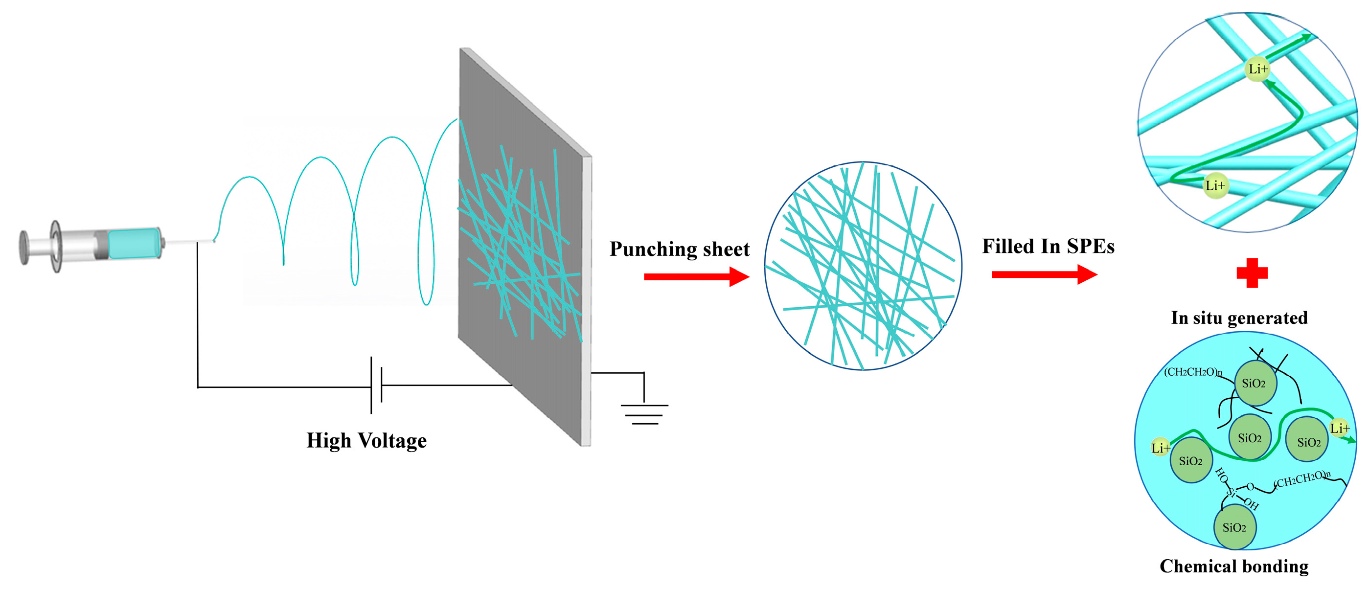
- Preparation of in-situ-generated spinning solution: PEO solution was added to 25 mL of anhydrous ethanol, then 10 mL of ammonia precursor solution and 0.2 mL of the first SiO2 nanosphere solution was added and stirred at room temperature. After complete dissolution, 0.347 g of TEOS was added drop-by-drop to the above solution, after which the stirring was continued to obtain the in situ SiO2 (45 nm)-PEO solution. The spinning solution (PEO/LiTFSI/ISF-10%SiO2) containing in-situ-generated 45 nm SiO2 nanospheres was obtained by adding the dried and dehydrated LITFSI to the in situ SiO2 (45 nm)-PEO solution (the molar ratio of PEO and LiTFSI is 16:1), and then this was evaporated in a vacuum oven at 50 °C for 6 h. Similarly, by changing the weight percentage of in situ SiO2 nanospheres in the system, the electrospinning solution of PEO/LiTFSI/ISF-5%SiO2 and PEO/LiTFSI/ISF-15%SiO2 was also prepared. The properties of SiO2 in the composite solid polymer electrolyte are shown in Table 1.
- (5)
- Preparation of the mechanically doped and in-situ-generated electrospun CPEs: the spinning solution was electrostatically spun under a high electrostatic pressure. By adjusting the technical parameters of electrospinning, the electrospun CPEs with a thickness between 50 and 200 μm was achieved. The as-spun electrolytes were then punched into 19 mm diameter discs and vacuum-dried for 24 h at 45 °C. Finally, the electrolytes were transferred into the glove box for a later use.
2.3. Structure Characterization
2.4. Electrochemical Characterization
3. Results and Discussion
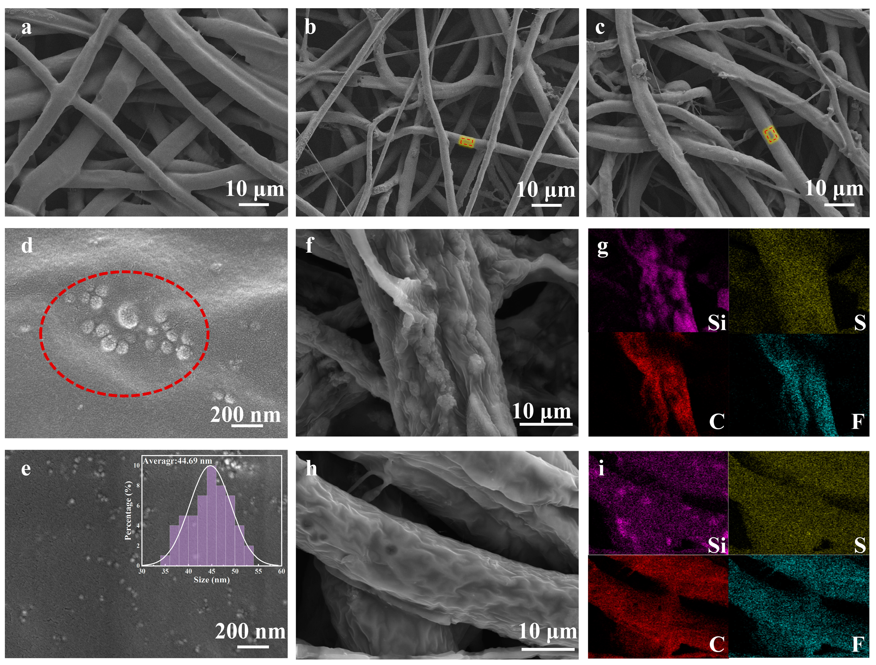
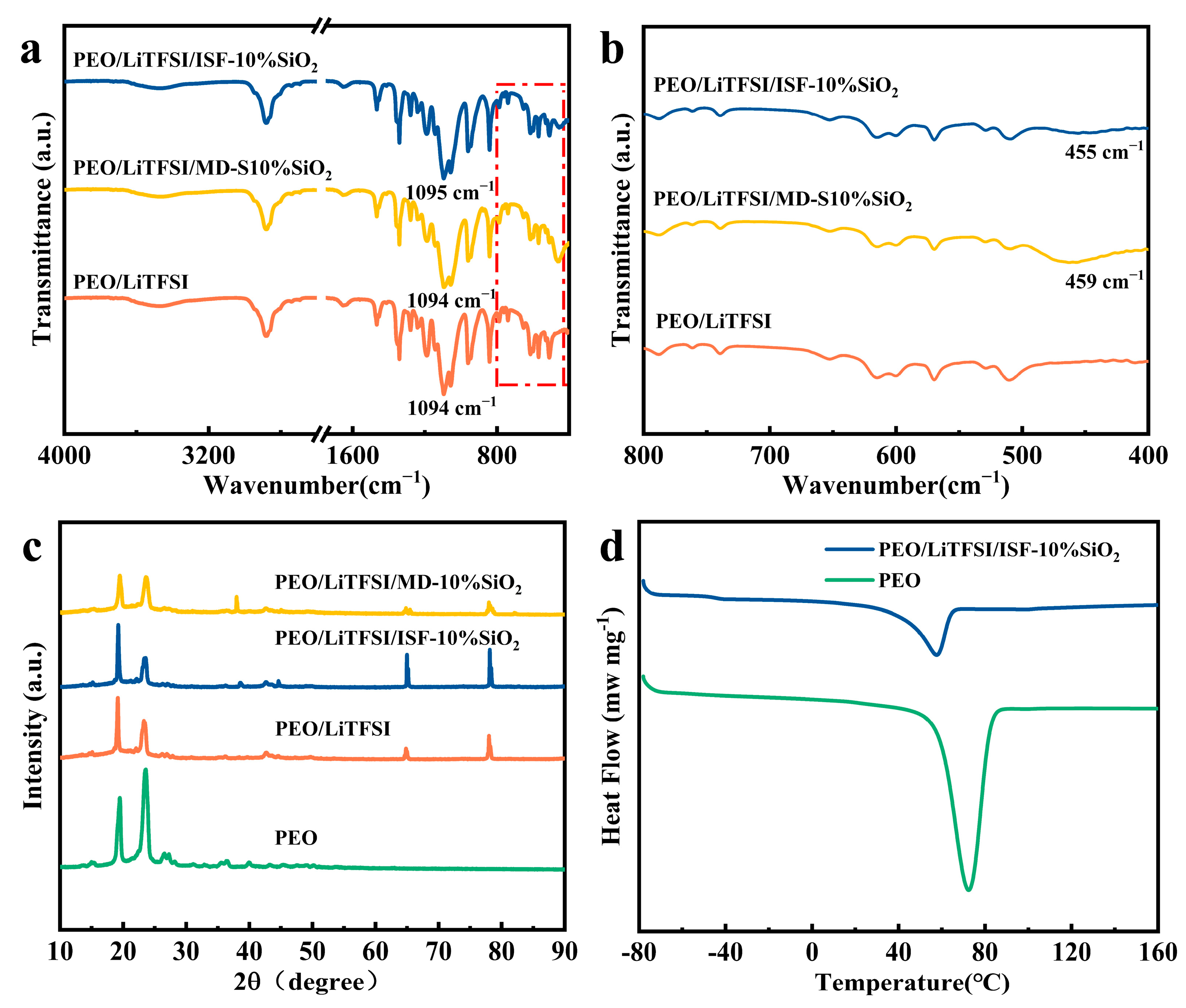
3.1. Microstructure and Morphology of the Electrospun SPEs
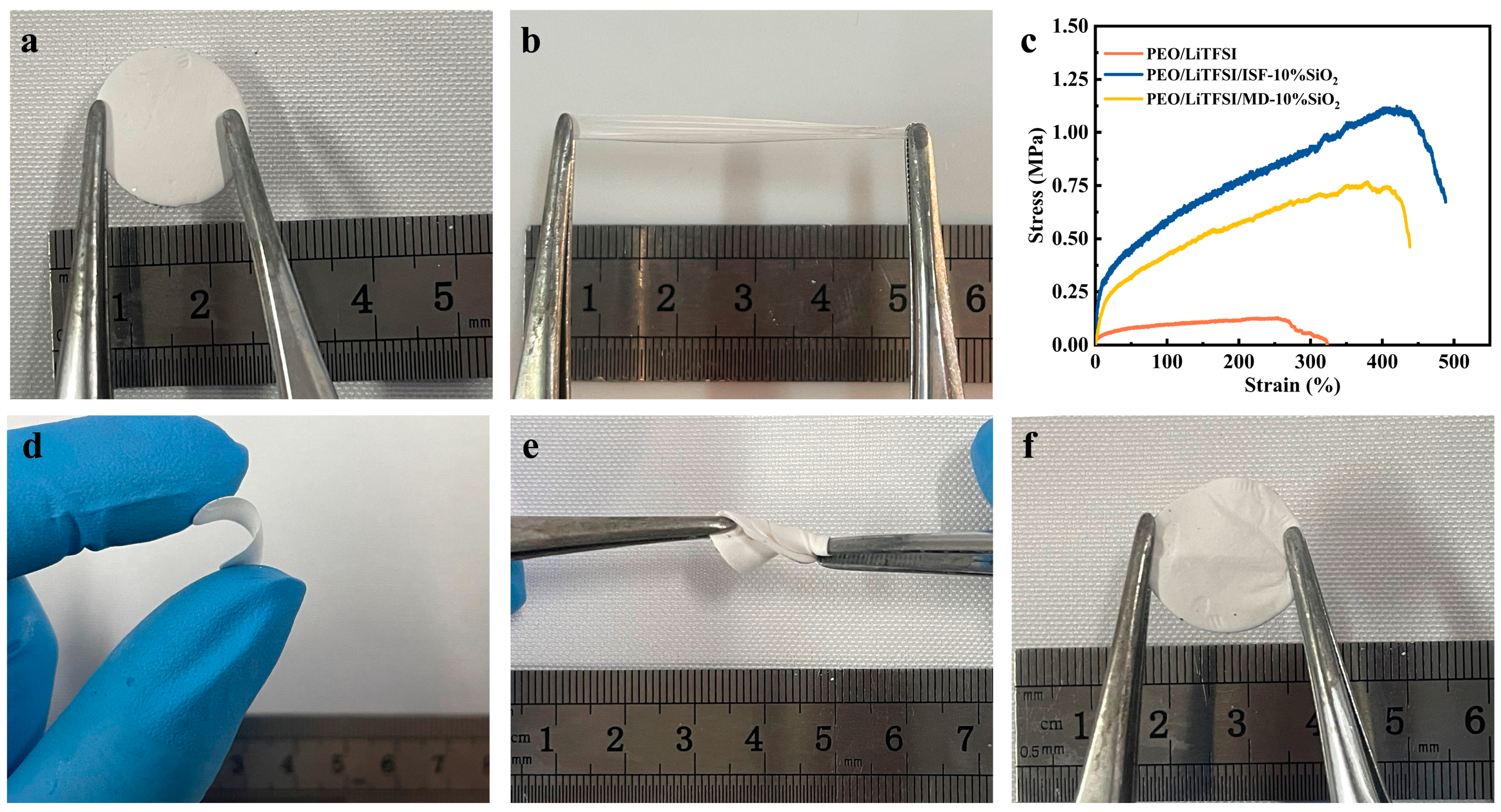
3.2. Mechanical Properties of As-Spun SPEs
3.3. Electrochemical Properties of the Electrospun SPEs
4. Conclusions
Author Contributions
Funding
Data Availability Statement
Acknowledgments
Conflicts of Interest
References
- Halalay, I.C.; Lukitsch, M.J.; Balogh, M.P.; Wong, C.A. Nanoindentation testing of separators for lithium-ion batteries. J. Power Source 2013, 238, 469–477. [Google Scholar] [CrossRef]
- Tikekar, M.D.; Choudhury, S.; Tu, Z.; Archer, L.A. Design principles for electrolytes and interfaces for stable lithium-metal batteries. Nat. Energy 2016, 1, 16114. [Google Scholar] [CrossRef]
- Feng, X.; Ouyang, M.; Liu, X.; Lu, L.; Xia, Y.; He, X. Thermal runaway mechanism of lithiumion battery for electric vehicles: A review. Energy Storage Mater. 2018, 10, 246–267. [Google Scholar] [CrossRef]
- Goodenough, J.B.; Singh, P. Review—Solid Electrolytes in Rechargeable Electrochemical Cells. J. Electrochem. Soc. 2015, 162, A2387–A2392. [Google Scholar] [CrossRef]
- Yue, L.; Ma, J.; Zhang, J.; Zhao, J.; Dong, S.; Liu, Z.; Cui, G.; Chen, L. All solid-state polymer electrolytes for high-performance lithiumion batteries. Energy Storage Mater. 2016, 5, 139–164. [Google Scholar] [CrossRef]
- Yu, X.; Gross, M.M.; Wang, S.; Manthiram, A. Aqueous Electrochemical Energy Storage with a Mediator-Ion Solid Electrolyte. Adv. Energy Mater. 2017, 7, 1602454. [Google Scholar] [CrossRef]
- Xia, S.; Wu, X.; Zhang, Z.; Cui, Y.; Liu, W. Practical Challenges and Future Perspectives of All-Solid-State Lithium-Metal Batteries. Chem 2019, 5, 753–785. [Google Scholar] [CrossRef]
- Thangadurai, V.; Narayanan, S.; Pinzaru, D. Garnet-type solid-state fast Li ion conductors for Li batteries: Critical review. Chem. Soc. Rev. 2014, 43, 4714–4727. [Google Scholar] [CrossRef]
- Zhang, X.; Xie, J.; Shi, F.; Lin, D.; Liu, Y.; Liu, W.; Pei, A.; Gong, Y.; Wang, H.; Liu, K.; et al. Vertically Aligned and Continuous Nanoscale Ceramic–Polymer Interfaces in Composite Solid Polymer Electrolytes for Enhanced Ionic Conductivity. Nano Lett. 2018, 18, 3829–3838. [Google Scholar] [CrossRef]
- Liang, B.; Tang, S.; Jiang, Q.; Chen, C.; Chen, X.; Li, S.; Yan, X. Preparation and characterization of PEO-PMMA polymer composite electrolytes doped with nano-Al2O. Electrochim. Acta 2015, 169, 334–341. [Google Scholar] [CrossRef]
- Fullerton-Shirey, S.K.; Maranas, J.K. Structure and Mobility of PEO/LiClO4 Solid Polymer Electrolytes Filled with Al2O3 Nanoparticles. J. Phys. Chem. C 2010, 114, 9196–9206. [Google Scholar] [CrossRef]
- Sassi, R.; Bond, R.R.; Cairns, A.; Finlay, D.D.; Guldenring, D.; Libretti, G.; Isola, L.; Vaglio, M.; Poeta, R.; Campana, M.; et al. PDF–ECG in clinical practice: A model for long–term preservation of digital 12–lead ECG data. J. Electrocardiol. 2017, 50, 776–780. [Google Scholar] [CrossRef]
- Berthier, C.; Gorecki, W.; Minier, M.; Armand, M.; Chabagno, J.; Rigaud, P. Microscopic investigation of ionic conductivity in alkali metal salts-poly(ethylene oxide) adducts. Solid State Ion. 1983, 11, 91–95. [Google Scholar] [CrossRef]
- Armand, M. Polymer solid electrolytes—An overview. Solid State Ion. 1983, 9–10, 745–754. [Google Scholar] [CrossRef]
- Croce, F.; Persi, L.; Scrosati, B.; Serraino-Fiory, F.; Plichta, E.; Hendrickson, M. Role of the ceramic fillers in enhancing the transport properties of composite polymer electrolytes. Electrochim. Acta 2001, 46, 2457–2461. [Google Scholar] [CrossRef]
- Sheng, O.; Jin, C.; Luo, J.; Yuan, H.; Fang, C.; Huang, H.; Gan, Y.; Zhang, J.; Xia, Y.; Liang, C.; et al. Ionic conductivity promotion of polymer electrolyte with ionic liquid grafted oxides for all-solid-state lithium–sulfur batteries. J. Mater. Chem. A 2017, 5, 12934–12942. [Google Scholar] [CrossRef]
- Huang, H.; Ding, F.; Zhong, H.; Li, H.; Zhang, W.; Liu, X.; Xu, Q. Nano-SiO2-embedded poly(propylene carbonate)-based composite gel polymer electrolyte for lithium–sulfur batteries. J. Mater. Chem. A 2018, 6, 9539–9549. [Google Scholar] [CrossRef]
- Zhao, X.G.; Jin, E.M.; Park, J.-Y.; Gu, H.-B. Hybrid polymer electrolyte composite with SiO2 nanofiber filler for solid-state dye-sensitized solar cells. Compos. Sci. Technol. 2014, 103, 100–105. [Google Scholar] [CrossRef]
- Wang, X.; Fu, X.; Wang, Y.; Zhong, W. A protein-reinforced adhesive composite electrolyte. Polymer 2016, 106, 43–52. [Google Scholar] [CrossRef] [Green Version]
- Liu, W.; Lee, S.W.; Lin, D.; Shi, F.; Wang, S.; Sendek, A.D.; Cui, Y. Enhancing ionic conductivity in composite polymer electrolytes with well-aligned ceramic nanowires. Nat. Energy 2017, 2, 17035. [Google Scholar] [CrossRef]
- Croce, F.; Appetecchi, G.B.; Persi, L.; Scrosati, B. Nanocomposite polymer electrolytes for lithium batteries. Nature 1998, 394, 456–458. [Google Scholar] [CrossRef]
- Fu, K.; Gong, Y.; Dai, J.; Gong, A.; Han, X.; Yao, Y.; Wang, C.; Wang, Y.; Chen, Y.; Yan, C.; et al. Flexible, solid-state, ion-conducting membrane with 3D garnet nanofiber networks for lithium batteries. Proc. Natl. Acad. Sci. USA 2016, 113, 7094–7099. [Google Scholar] [CrossRef] [PubMed] [Green Version]
- Li, D.; Chen, L.; Wang, T.; Fan, L.-Z. 3D Fiber-Network-Reinforced Bicontinuous Composite Solid Electrolyte for Dendrite-free Lithium Metal Batteries. ACS Appl. Mater. Interfaces 2018, 10, 7069–7078. [Google Scholar] [CrossRef] [PubMed]
- Krutyeva, M.; Wischnewski, A.; Monkenbusch, M.; Willner, L.; Maiz, J.; Mijangos, C.; Arbe, A.; Colmenero, J.; Radulescu, A.; Holderer, O.; et al. Effect of Nanoconfinement on Polymer Dynamics: Surface Layers and Interphases. Phys. Rev. Lett. 2013, 110, 108303. [Google Scholar] [CrossRef] [PubMed] [Green Version]
- Huo, H.; Chen, Y.; Luo, J.; Yang, X.; Guo, X.; Sun, X. Rational Design of Hierarchical “Ceramic-in-Polymer” and “Polymer-in-Ceramic” Electrolytes for Dendrite-Free Solid-State Batteries. Adv. Energy Mater. 2019, 9, 1804004. [Google Scholar] [CrossRef]
- Raghavan, P.; Choi, J.-W.; Ahn, J.-H.; Cheruvally, G.; Chauhan, G.S.; Ahn, H.-J.; Nah, C. Novel electrospun poly(vinylidene fluoride-co-hexafluoropropylene)—In situ SiO2 composite membrane-based polymer electrolyte for lithium batteries. J. Power Source 2008, 184, 437–443. [Google Scholar] [CrossRef]
- Gao, L.; Li, J.; Sarmad, B.; Cheng, B.; Kang, W.; Deng, N. A 3D polyacrylonitrile nanofiber and flexible polydimethylsiloxane macromolecule combined all-solid-state composite electrolyte for efficient lithium metal batteries. Nanoscale 2020, 12, 14279–14289. [Google Scholar] [CrossRef]
- Zhang, L.X.; Li, Y.Z.; Shi, L.W.; Yao, R.J.; Xia, S.S.; Wang, Y.; Yang, Y.P. Electrospun Polyethylene Oxide (PEO)-Based Composite polymeric nanofiber electrolyte for Li-Metal Battery. J. Phys. Conf. Ser. 2022, 2353, 012004. [Google Scholar] [CrossRef]
- Freitag, K.M.; Kirchhain, H.; van Wüllen, L.; Nilges, T. Enhancement of Li Ion Conductivity by Electrospun Polymer Fibers and Direct Fabrication of Solvent-Free Separator Membranes for Li Ion Batteries. Inorg. Chem. 2017, 56, 2100–2107. [Google Scholar] [CrossRef]
- Huang, Z.; Kolbasov, A.; Yuan, Y.; Cheng, M.; Xu, Y.; Rojaee, R.; Deivanayagam, R.; Foroozan, T.; Liu, Y.; Amine, K.; et al. Solution Blowing Synthesis of Li-Conductive Ceramic Nanofibers. ACS Appl. Mater. Interfaces 2020, 12, 16200–16208. [Google Scholar] [CrossRef]
- Cai, M.; Yuan, D.; Zhang, X.; Pu, Y.; Liu, X.; He, H.; Zhang, L.; Ning, X. Lithium ion battery separator with improved performance via side-by-side bicomponent electrospinning of PVDF-HFP/PI followed by 3D thermal crosslinking. J. Power Source 2020, 461, 228123. [Google Scholar] [CrossRef]
- Yang, J.M.; Fan, C.-S.; Wang, N.-C.; Chang, Y.-H. Evaluation of membrane preparation method on the performance of alkaline polymer electrolyte: Comparison between poly(vinyl alcohol)/chitosan blended membrane and poly(vinyl alcohol)/chitosan electrospun nanofiber composite membranes. Electrochimica Acta 2018, 266, 332–340. [Google Scholar] [CrossRef]
- Chang, S.; Chen, J.; Su, J.; Yang, Y.; Sun, H. Seasonal comparison of bacterial communities in rhizosphere of alpine cushion plants in the Himalayan Hengduan Mountains. Plant Divers. 2018, 40, 209–216. [Google Scholar] [CrossRef]
- Lin, D.; Liu, W.; Liu, Y.; Lee, H.R.; Hsu, P.-C.; Liu, K.; Cui, Y. High Ionic Conductivity of Composite Solid Polymer Electrolyte via In Situ Synthesis of Monodispersed SiO2 Nanospheres in Poly(ethylene oxide). Nano Lett. 2016, 16, 459–465. [Google Scholar] [CrossRef]
- Zhang, J.; Zhao, N.; Zhang, M.; Li, Y.; Chu, P.K.; Guo, X.; Di, Z.; Wang, X.; Li, H. Flexible and ion-conducting membrane electrolytes for solid-state lithium batteries: Dispersion of garnet nanoparticles in insulating polyethylene oxide. Nano Energy 2016, 28, 447–454. [Google Scholar] [CrossRef]
- Zhao, H.; Deng, N.; Yan, J.; Kang, W.; Ju, J.; Wang, L.; Li, Z.; Cheng, B. Effect of OctaphenylPolyhedral oligomeric silsesquioxane on the electrospun Poly-m-phenylene isophthalamid separators for lithium-ion batteries with high safety and excellent electrochemical performance. Chem. Eng. J. 2019, 356, 11–21. [Google Scholar] [CrossRef]
- Papananou, H.; Perivolari, E.; Chrissopoulou, K.; Anastasiadis, S.H. Tuning polymer crystallinity via the appropriate selection of inorganic nanoadditives. Polymer 2018, 157, 111–121. [Google Scholar] [CrossRef]
- Tang, C.; Hackenberg, K.; Fu, Q.; Ajayan, P.M.; Ardebili, H. High Ion Conducting Polymer Nanocomposite Electrolytes Using Hybrid Nanofillers. Nano Lett. 2012, 12, 1152–1156. [Google Scholar] [CrossRef]
- Noor, S.A.M.; Ahmad, A.; Talib, I.A.; Rahman, M.Y.A. Morphology, chemical interaction, and conductivity of a PEO-ENR50 based on solid polymer electrolyte. Ionics 2009, 16, 161–170. [Google Scholar] [CrossRef]
- Rajendran, S.; Kannan, R.; Mahendran, O. Ionic conductivity studies in poly(methylmethacrylate)–polyethlene oxide hybrid polymer electrolytes with lithium salts. J. Power Source 2001, 96, 406–410. [Google Scholar] [CrossRef]
- Deng, J.-H.; Cao, D.-Q.; Li, L.-J.; Chen, Y.-P.; Zhang, G.-Q.; Yang, X.-Q. Electrospun nanofiber separator derived from nano-SiO2-modified polyimide with superior mechanical flexibility for high-performance lithium-ion battery. J. Mater. Sci. 2021, 56, 15215–15228. [Google Scholar] [CrossRef]
- Ji, J.; Li, B.; Zhong, W.-H. Simultaneously enhancing ionic conductivity and mechanical properties of solid polymer electrolytes via a copolymer multi-functional filler. Electrochimica Acta 2010, 55, 9075–9082. [Google Scholar] [CrossRef]
- Zhang, Y.; Wang, X.; Feng, W.; Zhen, Y.; Zhao, P.; Li, L.; Cai, Z. The effects of the size and content of BaTiO3 nanoparticles on solid polymer electrolytes for all-solid-state lithium-ion batteries. J. Solid State Electrochem. 2019, 23, 749–758. [Google Scholar] [CrossRef]
- Wieczorek, W.; Stevens, J.R.; Florjańczyk, Z. Composite polyether based solid electrolytes. The Lewis acid-base approach. Solid State Ion. 1996, 85, 67–72. [Google Scholar] [CrossRef]
- Sun, H.Y.; Sohn, H.; Yamamoto, O.; Takeda, Y.; Imanishi, N. Enhanced Lithium-Ion Transport in PEO-Based Composite Polymer Electrolytes with Ferroelectric BaTiO. J. Electrochem. Soc. 2019, 146, 1672–1676. [Google Scholar] [CrossRef]
- de Bruin, B.; Boerakker, M.J.; Donners, J.J.J.M.; Christiaans, B.E.C.; Schlebos, P.P.J.; De Gelder, R.; Smits, J.M.M.; Spek, A.L.; Gal, A.W. Oxidation of RhI(olefin) Fragments to 2-Rhoda(III)oxetanes. Angew. Chem. Int. Ed. 1997, 36, 2064–2067. [Google Scholar] [CrossRef]
- Lei, R.; Yang, Y.; Yu, C.; Xu, Y.; Li, Y.; Li, J. A facile preparation of PEO–LiClO4–fumed SiO2 composite solid-state electrolyte with improved electrochemical performance for lithium-metal batteries. Sustain. Energy Fuels 2021, 5, 1538–1547. [Google Scholar] [CrossRef]


| Samples | Diameter/nm | Content/wt% | Adding Ways |
|---|---|---|---|
| PEO/LiTFSI/ISF-5%SiO2 | 45 | 5 | In situ generated |
| PEO/LiTFSI/ISF-10%SiO2 | 45 | 10 | In situ generated |
| PEO/LiTFSI/ISF-15%SiO2 | 45 | 15 | In situ generated |
| PEO/LiTFSI/MD-10%SiO2 | 45 | 10 | Mechanical doping |
| PEO/LiTFSI/MD-S10%SiO2 | 12 | 10 | Mechanical doping |
| Samples | Tm/°C | ΔHm/J g−1 | /% |
|---|---|---|---|
| PEO | 72.36 | −170.10 | 95.67 |
| PEO/LiTFSI/ISF-10%SiO2 | 57.59 | −44.62 | 25.10 |
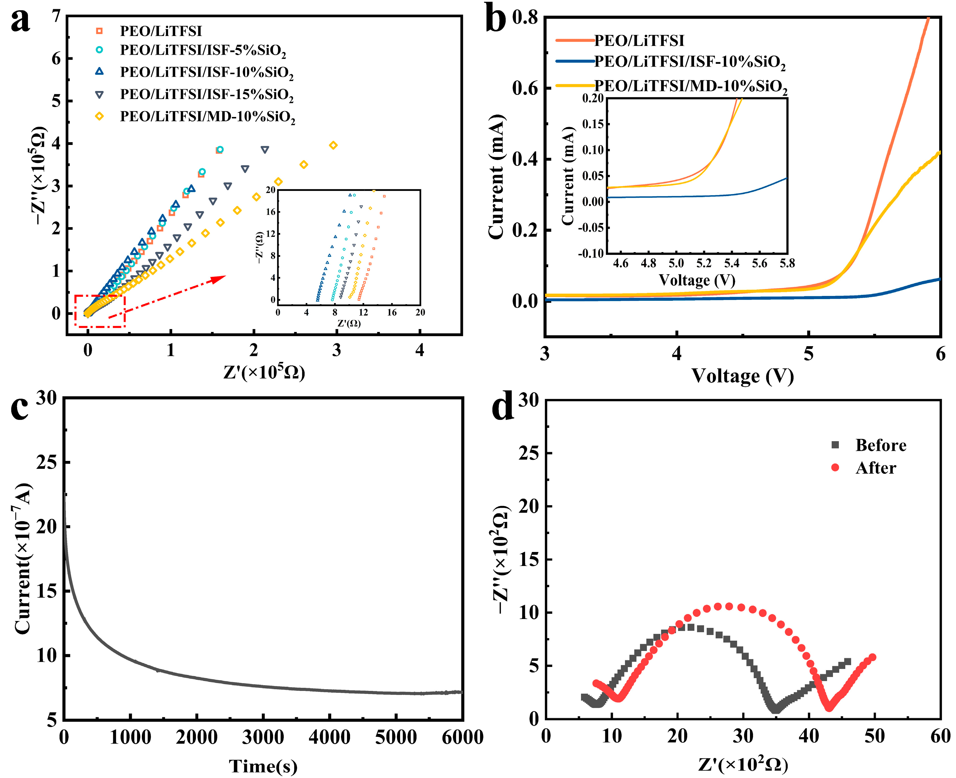
| Samples | d/cm | Rb/Ω | σ/S cm−1 |
|---|---|---|---|
| PEO/LiTFSI | 1.14 × 10⁻² | 11.370 | 5.1 × 10⁻⁴ |
| PEO/LiTFSI/ISF-5%SiO2 | 1.29 × 10⁻² | 7.640 | 8.6 × 10⁻⁴ |
| PEO/LiTFSI/ISF-10%SiO2 | 1.12 × 10⁻² | 5.571 | 1.03 × 10⁻³ |
| PEO/LiTFSI/ISF-15%SiO2 | 1.29 × 10⁻² | 8.814 | 7.5 × 10⁻⁴ |
| PEO/LiTFSI/MD-10%SiO2 | 1.07 × 10⁻² | 10.090 | 5.4 × 10⁻⁴ |
| Samples | I0/μA | IS/μA | R0/Ω | RS/Ω | ΔV/mV | T/°C | |
| PEO/LiTFSI/ISF-10%SiO2 | 2.26 | 0.71 | 760.6 | 1094 | 10 | 20 | 0.282 |
Disclaimer/Publisher’s Note: The statements, opinions and data contained in all publications are solely those of the individual author(s) and contributor(s) and not of MDPI and/or the editor(s). MDPI and/or the editor(s) disclaim responsibility for any injury to people or property resulting from any ideas, methods, instructions or products referred to in the content. |
© 2023 by the authors. Licensee MDPI, Basel, Switzerland. This article is an open access article distributed under the terms and conditions of the Creative Commons Attribution (CC BY) license (https://creativecommons.org/licenses/by/4.0/).
Share and Cite
Shi, L.; Zhang, L.; Yang, Y.; Zhang, H.; Yao, R.; Yuan, C.; Cheng, S. In Situ Nano-SiO2 Electrospun Polyethylene-Oxide-Based Nano-Fiber Composite Solid Polymer Electrolyte for High-Performance Lithium-Ion Batteries. Nanomaterials 2023, 13, 1294. https://doi.org/10.3390/nano13071294
Shi L, Zhang L, Yang Y, Zhang H, Yao R, Yuan C, Cheng S. In Situ Nano-SiO2 Electrospun Polyethylene-Oxide-Based Nano-Fiber Composite Solid Polymer Electrolyte for High-Performance Lithium-Ion Batteries. Nanomaterials. 2023; 13(7):1294. https://doi.org/10.3390/nano13071294
Chicago/Turabian StyleShi, Luwei, Longxing Zhang, Yanping Yang, Haipeng Zhang, Ruijie Yao, Caoquan Yuan, and Shaobo Cheng. 2023. "In Situ Nano-SiO2 Electrospun Polyethylene-Oxide-Based Nano-Fiber Composite Solid Polymer Electrolyte for High-Performance Lithium-Ion Batteries" Nanomaterials 13, no. 7: 1294. https://doi.org/10.3390/nano13071294