
Numerical Study on the Buckling Behavior of FG Porous Spherical Caps Reinforced by Graphene Platelets
by
 , and
, and
Zhimin Zhou
1,
Yun Wang
1,
Suying Zhang
1,
Rossana Dimitri
2,
Francesco Tornabene
2,* and
and
Kamran Asemi
3 1
Hangzhou Vocational & Technical College, Hangzhou 310018, China
2
Department of Innovation Engineering, Faculty of Engineering, University of Salento, 73100 Lecce, Italy
3
Department of Mechanical Engineering, Islamic Azad University, North Tehran Branch, Tehran 1477893855, Iran
*
Author to whom correspondence should be addressed.
Nanomaterials 2023, 13(7), 1205; https://doi.org/10.3390/nano13071205
Submission received: 3 March 2023
/
Revised: 16 March 2023
/
Accepted: 20 March 2023
/
Published: 28 March 2023
Abstract
:The buckling response of functionally graded (FG) porous spherical caps reinforced by graphene platelets (GPLs) is assessed here, including both symmetric and uniform porosity patterns in the metal matrix, together with five different GPL distributions. The Halpin–Tsai model is here applied, together with an extended rule of mixture to determine the elastic properties and mass density of the selected shells, respectively. The equilibrium equations of the pre-buckling state are here determined according to a linear three-dimensional (3D) elasticity basics and principle of virtual work, whose solution is determined from classical finite elements. The buckling load is, thus, obtained based on the nonlinear Green strain field and generalized geometric stiffness concept. A large parametric investigation studies the sensitivity of the natural frequencies of FG porous spherical caps reinforced by GPLs to different parameters, namely, the porosity coefficients and distributions, together with different polar angles and stiffness coefficients of the elastic foundation, but also different GPL patterns and weight fractions of graphene nanofillers. Results denote that the maximum and minimum buckling loads are reached for GPL-X and GPL-O distributions, respectively. Additionally, the difference between the maximum and minimum critical buckling loads for different porosity distributions is approximately equal to 90%, which belong to symmetric distributions. It is also found that a high weight fraction of GPLs and a high porosity coefficient yield the highest and lowest effects of the structure on the buckling loads of the structure for an amount of 100% and 12.5%, respectively.
1. Introduction
Nowadays, there is a high demand for materials with a low weight and high strength, for many engineering applications. Among them, FG-GPL porous materials have attracted the interest of many researchers due to their mechanical potentials in aerospace and marine industries. A large variety of works from the scientific literature have focused on the static and/or dynamic behavior of different structural members, such as beams, plates, shells, with arbitrary shapes and made of composite materials [1,2,3,4]. For example, Zhang et al. [5] applied the DSC-regularized Dirac-delta method using the Timoshenko theory to explore the dynamics of FG-GPL porous beams resting on elastic foundations and subjected to a moving load. Based on a shear and normal deformation theory and by employing the Ritz approach, Priyanka et al. [6] investigated the stability and dynamic responses of porous beams made of FG-GPLs. Moreover, the free vibrations of rotating, FG-GPL, porous Timoshenko beams were studied by Binh et al. [7], using the generalized differential quadrature method (GDQM). Xu et al. [8] adopted the differential transformation method to investigate the free vibration behavior of FG-GPL porous beams based on the Euler–Bernoulli beam theory under a spinning movement. Ganapathi et al. [9] proposed a trigonometric shear deformation theory, including a thickness stretching effect, to study the dynamic problem of curved beams made of FG-GPL porous nanocomposites, and proposed a closed-form solution as valid tool for further computational investigations. Yas and Rahimi [10] applied the GDQM to study the thermal vibration of FG-GPL, porous Timoshenko beams. Safarpour et al. [11] applied the 3D elasticity theory in conjunction with the GDQM to study the bending and free vibration behavior of porous annular and circular plates made of FG-GPLs under different boundary conditions. A novel computational method was proposed by Nguyen et al. [12] to evaluate the static bending and free vibration response of FG-GPL porous plates based on a first-order shear deformation theory (FSDT), while using a polygonal mesh with parabolic shape functions. Furthermore, the nonlinear free vibrations of porous plates made of FG-GPL nanocomposites, resting on an elastic foundation, were investigated using the GDQ approach by Gao et al. [13], using classical plate theory (CPT) and von Kármán-type nonlinearities. The same FSDT basics were applied by Saidi et al. [14] to study analytically the stability and vibrations of FG-GPL porous plates under an aerodynamical loading. The classical finite element approach and Rayleigh-Ritz procedure for a comprehensive investigation of the free and forced vibration behavior, and the static response of FG-GPL porous annular sector plates, were considered by Asemi et al. [15] using an FSDT approach. In addition, Phan [16] applied a refined plate theory to analyze the free and forced vibrations of porous plates made of FG-GPL nanocomposites, while using the (NURBS) non-uniform rational B-spline approximations. An analytical solution to the wave-propagation problem of FG-GPL porous plates was presented by Gao et al. [17], based on different plate theories, such as CPT, FSDT, or higher order theories (HSDTs). Zhou et al. [18] combined the 3D elasticity theory and GDQM to assess the free vibrations of FG-GPL porous plates, whereas in Ref. [19], the authors proposed a multiple scale approach and Galerkin method in order to define the nonlinear, forced vibration response of porous, thin, rectangular plates made of FG-GPL nanocomposites, including the von Kármán-type nonlinearities. Furthermore, a deep review on FG-GPL porous structures was performed by Kiarasi et al. [20]. The fabrication issues of these structures represent a challenging aspect for many practical applications. A novel quadrilateral element was proposed by Ton-That et al. [21], in line with the FSDT and Chebyshev polynomials, to analyze FG-GPL porous plates/shells. In addition, a variational differential quadrature (VDQ) was proposed by Ansari et al. [22] for solving the free-vibration response of post-buckled, arbitrarily shaped porous plates made of FG-GPL nanocomposites, based upon a third-order shear deformation theory (TSDT). The static and free-vibration analysis of FG-GPL annular plates, cylindrical shells and truncated conical shells, with various boundary conditions, within a three-dimensional elasticity theory, were also investigated by Safarpour et al. [23]. Bahaadini [24] defined a further analytical solution to the free vibration problem of FG-GPL, porous, truncated conical shells, according to a Love’s first approximation theory, while examining the influences of porosity coefficients, weight fractions and geometries of GPLs, on the free vibration of the structure. Babaei and his coauthors analyzed the stress-wave propagation and natural frequencies of porous joined conical-cylindrical shells made of FG-GPLs [25] and joined conical-cylindrical-conical shells [26] by using the classical finite element method (FEM). Based on the Donnell’s theory and the Galerkin approach, the internal resonance of metal foam cylindrical shells made of FG- GPLs was studied by Ye and Wang [27]. In the further work [28], the authors employed the Galerkin method and an improved version of Donnell nonlinear shell theory to investigate the nonlinear vibration of metal foam cylinders reinforced with GPLs. Moradi et al. [29] applied the moving least squares (MLSs) interpolations using an axisymmetric model to analyze stress waves’ propagation in FG-GPL, porous, thick cylinders in a thermal gradient environment. Based on the FSDT, Salehi et al. [30] solved analytically the nonlinear vibration of imperfect, FG-GPL, porous nanocomposite cylindrical shells, whereas in Ref. [31] the authors applied the GDQM to investigate the free vibration of sandwich pipes, considering the effects of porosity and a GPL reinforcement on the conveying fluid flow. Among the recent literature, Zhou et al. [32] examined the flutter and vibration properties of FG-GPL, porous cylindrical panels under a supersonic flow. At the same time, the vibration of FG-GPL porous shells was analytically investigated by Ebrahimi et al. [33]. Pourjabari et al. [34] analytically investigated the effect of porosity on the free and forced-vibration characteristics of GPL-reinforcement composite cylindrical shells in a nonlocal sense, based on a modified strain gradient theory (MSGT). In line with the previous works, a limited attention has been paid to the buckling response of FG-GPL porous materials and structures. Among the available literature, Zhou et al. [35] presented an accurate nonlinear buckling study of FG-GPL, porous, composite cylindrical shells based on Donnell’s theory and HSDT. Shahgholian-Ghahfarokhi et al. [36,37] investigated the torsional buckling behavior of FG-GPL, porous cylindrical shells, according to a FSDT and Rayleigh-Ritz method. Similarly, Yang [38] applied the Chebyshev polynomials-based Ritz method to study the natural frequencies and buckling response of FG-GPL porous rectangular plates, using the FSDT approach. Dong [39] investigated the buckling behavior of spinning cylindrical shells made of FG-GPL porous nanocomposites, while applying a FSDT and Galerkin approach. A novel numerical DQ-FEM solution to investigating the buckling and post-buckling of FG-GPL porous plates with different shapes and boundary conditions was applied by Ansari et al. [40]. Kitipornchai [41] analyzed the natural frequencies and elastic buckling of FG-GPL porous beams using the Timoshenko beam approach and the Ritz method. Twinkle et al. [42] focused on the impacts of grading, porosity and edge loads on the natural frequency and buckling problems of porous cylindrical panels made of FG-GPLs. Nguyen [43] investigated the buckling, instability and natural-frequency response of FG porous plates reinforced by GPLs using three-variable higher order isogeometric analysis (IGA). Rafiei Anamagh and Bediz [44], instead, applied the FSDT to study the free vibration and buckling behavior of porous plates made of FG-GPLs using a spectral Chebyshev approach.
In the available literature, it seems that the static, buckling and dynamic behavior of porous spherical shells made of FG-GPLs has not been surveyed so far, despite their geometry being of great interest in various engineering applications, such as heat exchangers or energy absorbers, among other applications in the areas of aerospace, mechanical engineering and marine engineering. Among the different shell geometries, a spherical shell structures, indeed, features a high strength with a simple geometry, even compared to a cylindrical structure. The design of such structural members considering only static loading conditions may fail in dynamic situations. In such context, we focus on the buckling capacities of spherical shells made of porous FG nanocomposites reinforced by graphene, due to their exceptional flexibility and enhanced physical features. It is well known from the literature, indeed, that porous ceramic nanocomposites can ensure different beneficial effects, such as a reduced electrical and thermal conductivity; low weight; reasonable hardness; and resistance to wear, corrosion and high-temperature applications [45]. Among the few works on spherical shell dynamics available in the literature, we cite Refs. [46,47], where a Ritz-Galerking procedure was proposed to solve a dynamic buckling problem for clumped spherical members. A finite difference method was applied, instead, in [48,49,50], to check for the sensitivity of the dynamic buckling response of spherical caps to some initial manufacturing imperfections. Novel theoretical shear deformation theories were applied in Refs. [51,52] to treat the buckling response of isotropic and orthotropic shallow spherical caps, whose problem was solved analytically by means of Chebychev series [51], or numerically according to classical finite elements [52]. At the present state, however, there is a general lack of works from the literature focusing on the dynamic buckling of GPL-reinforced porous nanocomposite spherical shells, whose aspects are explored here according to the 3D elasticity basics and Green deformation nonlinearities, rather than common shell theories and Von-Karman nonlinearities, as proposed in [53].
The equilibrium equations of a pre-buckling state are determined from the principle of virtual work, whose solution is found according to classical finite elements. The buckling loads are obtained according to the nonlinear Green strain field and the generalized geometric stiffness concept, for spherical caps featuring a uniform and non-uniform pattern of GPLs in the metallic matrix, including open-cell internal pores and for various porosity distributions along the shell’s thickness with uniform and symmetric FG patterns. More specifically, five different patterns of GPL dispersion pattern are assumed throughout the shell’s thickness, namely, a FG GPL-X, A, V, UD and O patterns. A systematic investigation checks for the effects of various porosity distributions and GPL patterns, along with the weight fractions and porosity coefficients of nano-fillers and different polar angles, on the buckling behavior of FG-GPL, porous spherical caps.
2. Theoretical Problem
2.1. Description of Geometry and Mechanical Properties
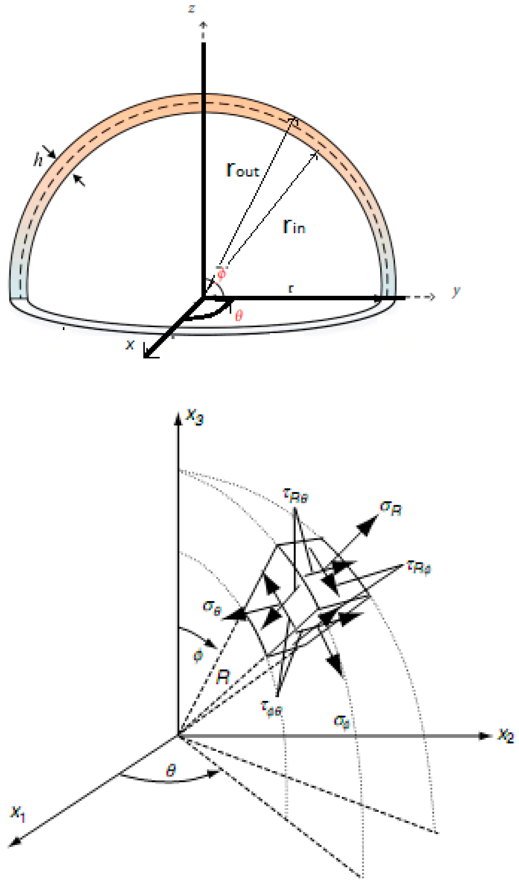
Let assume a spherical cap with uniform thickness and mean radius of . The outer and inner radii of the spherical cap are denoted as reported in Figure 1. The spherical cap is defined using the spherical coordinates that can be defined as follows: , and .
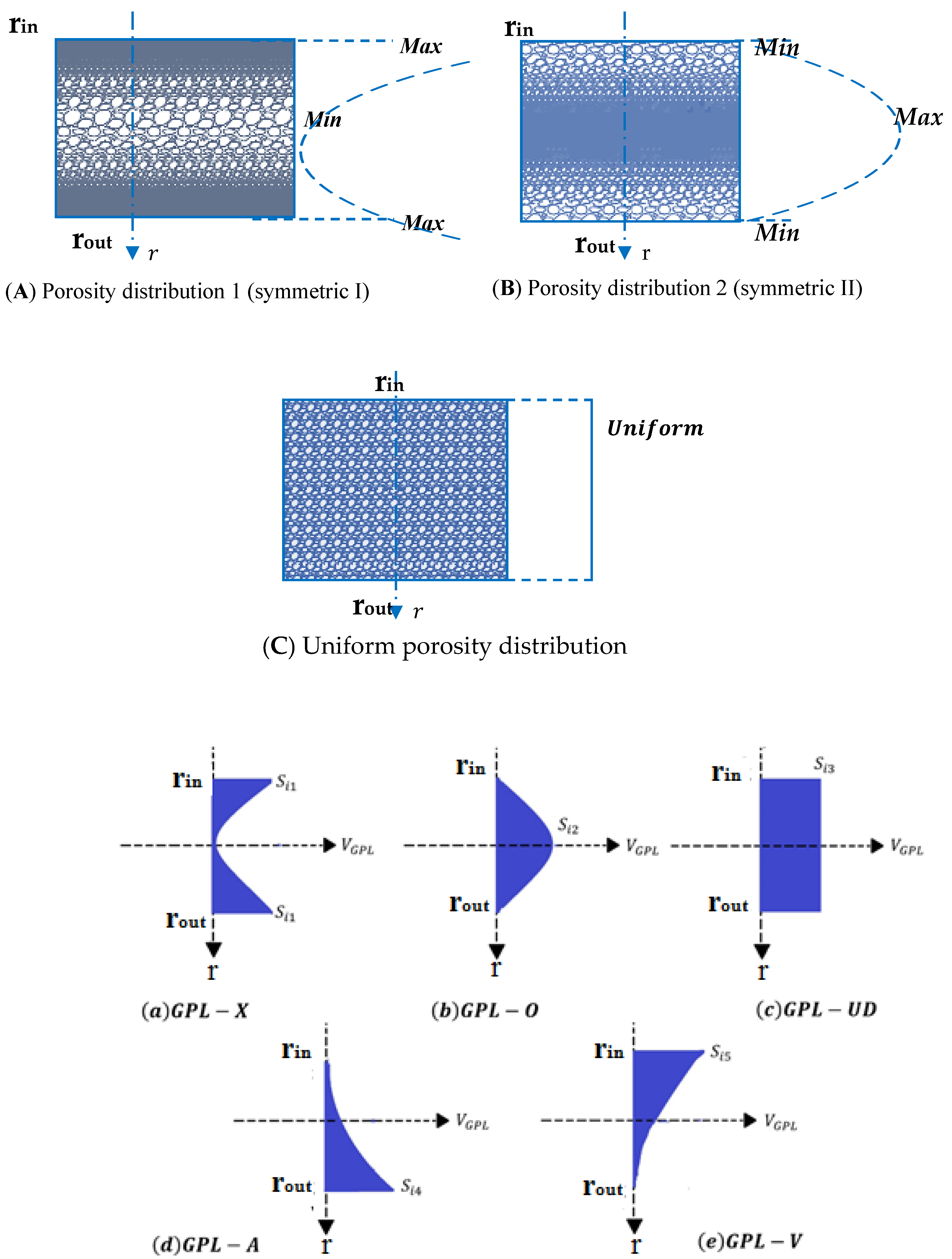
As can be seen in Figure 2, two types of non-uniform symmetric distributions and a uniform one are assumed in the present work, such that three different porosity profiles are here considered throughout the thickness of the spherical cap. In distribution 1, the porosity is nonlinear and symmetric. Furthermore, the distribution around the mid-radius is larger than the corresponding one around the external surfaces of the structure. In distribution 2, the porosity is also nonlinear and symmetric, but the porosity near the inner and outer surfaces of the spherical cap is higher than that one around the mid-radius. Equations (1)–(3) define mathematically the distributions of the material properties considering the effect of porosity, for the three selected distributions. At the same time, Figure 2 reports the five GPL distribution profiles throughout the spherical cap, thickness-wise, which are defined next [25,26]. More specifically, the mechanical properties refer to the mass density , Young’s modulus and shear modulus of porous nanocomposite spherical caps [54,55,56,57,58].
- -
- Porosity distribution 1
- -
- Porosity distribution 2
- -
- Uniform porosity distribution
In addition, and refer to the coefficients of porosity for the first two profiles, respectively; and stand for the mass density coefficients for these two distributions, respectively; α and α′ are two parameters referring to a uniform porosity profile. For an increased size and density of the internal cavities, the porosity increases, with a subsequent reduction of the mechanical properties.
The relation between the elasticity modulus and density for an open-cell metal foam is assumed as [58,59]
which is adopted to derive the relation between porosity and mass density coefficients for various porosity patterns; i.e.,
Here, we assume that the masses of spherical caps with various porosity patterns and GPL dispersions are identical. To compare the stiffness of different distributions, indeed, the analyses should be implemented for shells with equal masses. Hence, the values of and can be evaluated for a fixed value of [38,39], as
According to Equation (6), the values of and can be estimated for a fixed value of , as shown in Table 1.
It can be seen that increases as the value of increases. When equals 0.6, becomes equal to 0.9612, which is near to the upper bound. Hereafter, is used within the numerical investigation. According to the Halpin–Tsai micromechanics model [60], the elasticity modulus of nanocomposites without internal cavities is defined as
with
where indices and stand for properties of the metallic matrix and graphene platelets, respectively; is the volumetric content of GPLs; and , and refer to the length, width and thickness of the nano-filler platelets, respectively.
Based on the rule of mixtures, the mass density and Poisson’s ratio of nanocomposite materials are defined as [61,62,63]
whereas
refers to the associated shear modulus. The volumetric content of GPLs, , is assumed to vary throughout the spherical cap’s thickness, having five different dispersion patterns (see Figure 2):
where and denote the upper limits of ; and subscript i = 1, 2 or 3 refers to various porosity distributions within each pattern. Moreover, stands for the total volumetric content of GPLs, which is defined in terms of the nanofiller weight fraction in the following form:
This is, in turn, used to derive and as
2.2. Governing Equations of the Problem
The stress–strain relations are defined in matrix form as
where the stress and strain field, together with the elasticity matrix , read as follows:
where is the Poisson’s ratio and denotes the Young’s modulus that depends on the r coordinate. Based on the linear elasticity theory, the strain field in spherical coordinate is defined as
with
and
In addition, u, v and w define the kinematic components along r, and directions, respectively. According to the above-mentioned relations, the linear strain relation can be rewritten as
where Q is the displacements vector and is an operator matrix involving the partial derivatives of a function
3. Finite Element Modeling
A FEM-based approach is now adopted to solve the governing equations of the problem, where the spherical cap is divided into 8–node linear brick elements. For element , the 3D kinematic field is approximated as
where is the matrix of linear shape functions in spherical coordinates, whereas refers to the nodal displacement vector of the element, which is defined as
The components of are
being the volume of each element; i.e.,
and
It is also
where , and are the nodal coordinates and is obtained by elimination of the ith row and jth column from V. Substituting Equation (26) into Equation (23) gives the strain matrix of element as
where
The FEM-based governing equations are determined from the principle of virtual work, where the potential energy U and virtual work of external loads are defined as
being the area under the external radial load , which is subjected to the external surface of a spherical cap. In a pre-buckling state, the displacement field can be considered to be small, and the nonlinear terms of strain–displacement relations vanish. Therefore, one may write
Therefore, based on the principle of virtual work, the static balance equation of the problem for each element in a pre-buckling state takes the following form
Equation (43) in compact form can be written as
where is the linear stiffness matrix and is the force matrix for each element, defined as
By assembling each element matrix, the equilibrium equation of the spherical cap in the pre-buckling state is obtained as
whose solution is determined in terms of the strain field in pre-buckling state for . Afterward, the stress field due to these deformations is used in the geometric stiffness matrix, as detailed in the following. Finally, in order to determine the governing equations of an instability problem, the following equation can be used:
Therefore, based on Equations (44) and (48), it is
In line with Equation (22), the linear and nonlinear terms of the kinematic relations have been considered in the strain energy of the shell. In the pre-buckling state, the radial displacement components or large deformations can be assumed to be small, whereas only the linear strain terms appear. At the buckling state, instead, the nonlinear kinematic relations have to be considered. Therefore, the following relation can be obtained:
can be rewritten as
where
and
In the last relation, refers to the stresses obtained in pre-buckling state. By substituting , we obtain
where
More in detail, it is
Thus, according to Equation (50), we have
Equation (50) can be redefined in the following form:
After the assembly of the element matrices, the following determinant should be assumed as null for the structure.
Note that and refer to the linear stiffness matrix and geometric stiffness matrix, respectively, which are computed using the Gauss 8-point numerical integration rules.
Hereafter, we assume the following clamped boundary conditions:
- -
- For a spherical cap with θ = 180°, ϕ = 180°, u, v, w (r, θ and ϕ = 0, 180°), = 1 at r = b.
- -
- For a spherical cap with θ = 180°, ϕ = 90°, u, v, w (r, θ and ϕ = 0, 90°), = 1 at r = b.
4. Numerical Results and Discussion
In this section, we discuss the numerical results in terms of buckling loads of an FG-GPL, porous spherical cap with clamped boundary conditions, for various volume or weight fractions of GPL, and for different GPL distribution patterns, porosity distributions and coefficients, along with two polar angles of the FG-GPL, porous spherical shell.
4.1. Validation
In order to verify our results, we started the analysis with a comparative evaluation of the buckling predictions using the commercial Ansys Workbench code, for an isotropic homogeneous spherical cap. Hence, the following changes were considered in our study: e0 = 0, γGPL = 0. As far as the mechanical properties are concerned, we assumed Em = 130 GPa, ρm = 8960 kg/m3, νm = 0.34 for the copper material. As geometrical dimensions, we assumed: a = 0.225 m, b = 0.25 m, θ = 180°, ϕ = 180°, 90°. In this way, the FG-GPL porous structure changes to an isotropic homogenous structure. The comparison between our results and predictions from Ansys Workbench is shown in Table 2, with an excellent agreement among them.
4.2. Parametric Analysis of the Buckling Load
We now study the effects of two polar angles, porosity coefficient, porosity distribution, GPL patterns and the weight fraction of GPL nanofillers (for the first time) on the buckling load of an FG-GPL, porous spherical cap with clamped boundaries. Hence, the following geometrical properties are considered: a = 0.225 m, b = 0.25 m, θ = 180°, ϕ = 180°, 90°. The materials is characterized by the following mechanical properties: Em = 130 GPa, ρm = 8960 kg/m3 and νm = 0.34 for the copper material [28]; and EGPL = 1.01 TPa, ρGPL = 1062.5 kg/m3, νGPL = 0.186, wGPL = 1.5 μm, lGPL = 2.5 μm and tGPL = 1.5 nm for GPLs.
Table 3 indicates the influences of two types of polar angles and various GPL patterns on the buckling load of the FG-GPL-reinforced, porous spherical structure, under the assumptions PD3, e0 = 0.2 and γ = 0.01 wt%. The extreme values of buckling load are related to GPLX and GPL-O distributions, respectively, which means that, when GPLs accumulate around the inner and outer surfaces of the shell, the stiffness reaches its highest value. Moreover, when GPLs are sparser around the outer and inner surfaces of the shell, the minimum buckling load is obtained. Note also that the critical buckling loads for a GPLA and GPL-V distributions are approximately the same. The results also show that the surface area of the shell increases by increasing the polar angle, and there are consecutive increases in the structural stiffness and buckling load.
The influences of two polar angles and various porosity distributions are reported in Table 4 (GPLX, e0 = 0.4, γ = 0.01 wt%), which shows that the maximum and minimum buckling loads belong to PD1 and PD2 distributions, respectively. PD1 provides higher structural stiffness, and PD2 gives the minimum stiffness of the spherical cap shell. The main difference between the extreme values of critical buckling load is approximately 90% for different porosity patterns. This means that the porosity distribution has a considerable effect on the buckling loads of FG-GPL, porous, spherical cap shells.
The influences of two polar angles and weight fractions of nanofillers on the buckling loads of FG-GPL, porous spherical shell (PD1, e0 = 0.5, GPLX) are given in Table 5. Note that, by increasing the weight fraction of GPLs, the critical buckling loads of shell increases significantly (approximately 100%), along with a small variation of the structural mass. This issue can be useful for aerospace structures where the high stiffness and low density are extremely important.
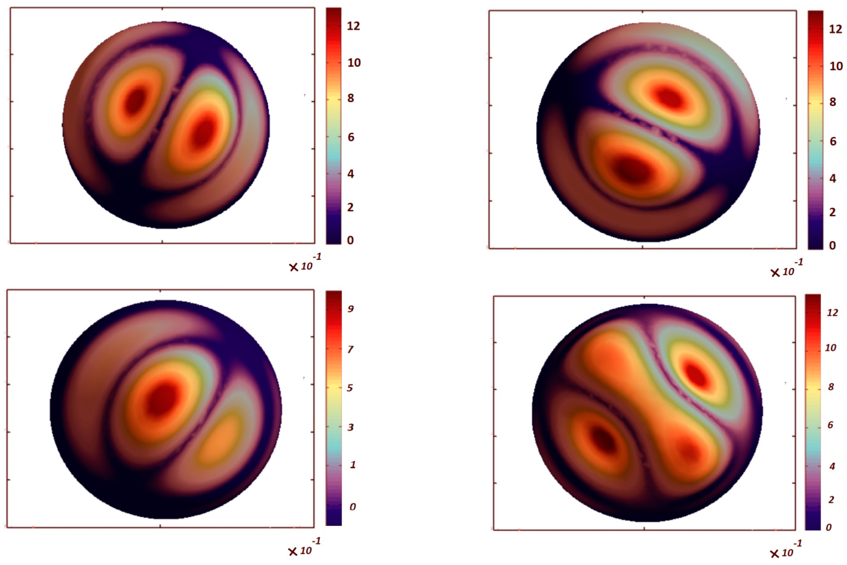
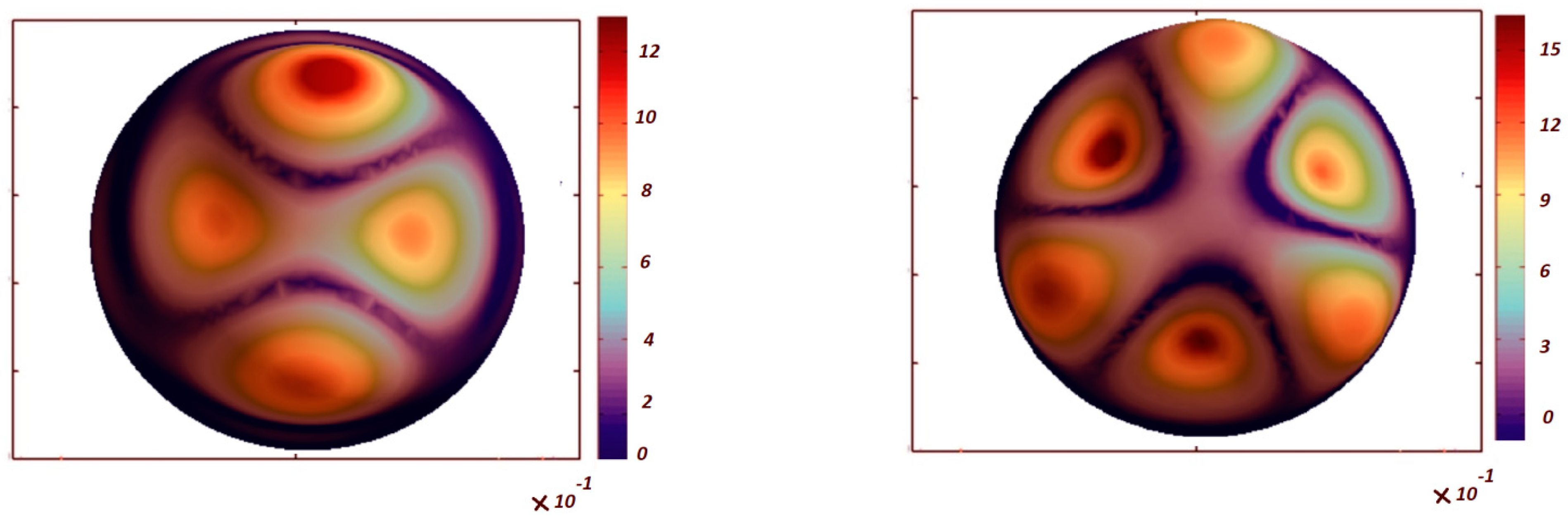
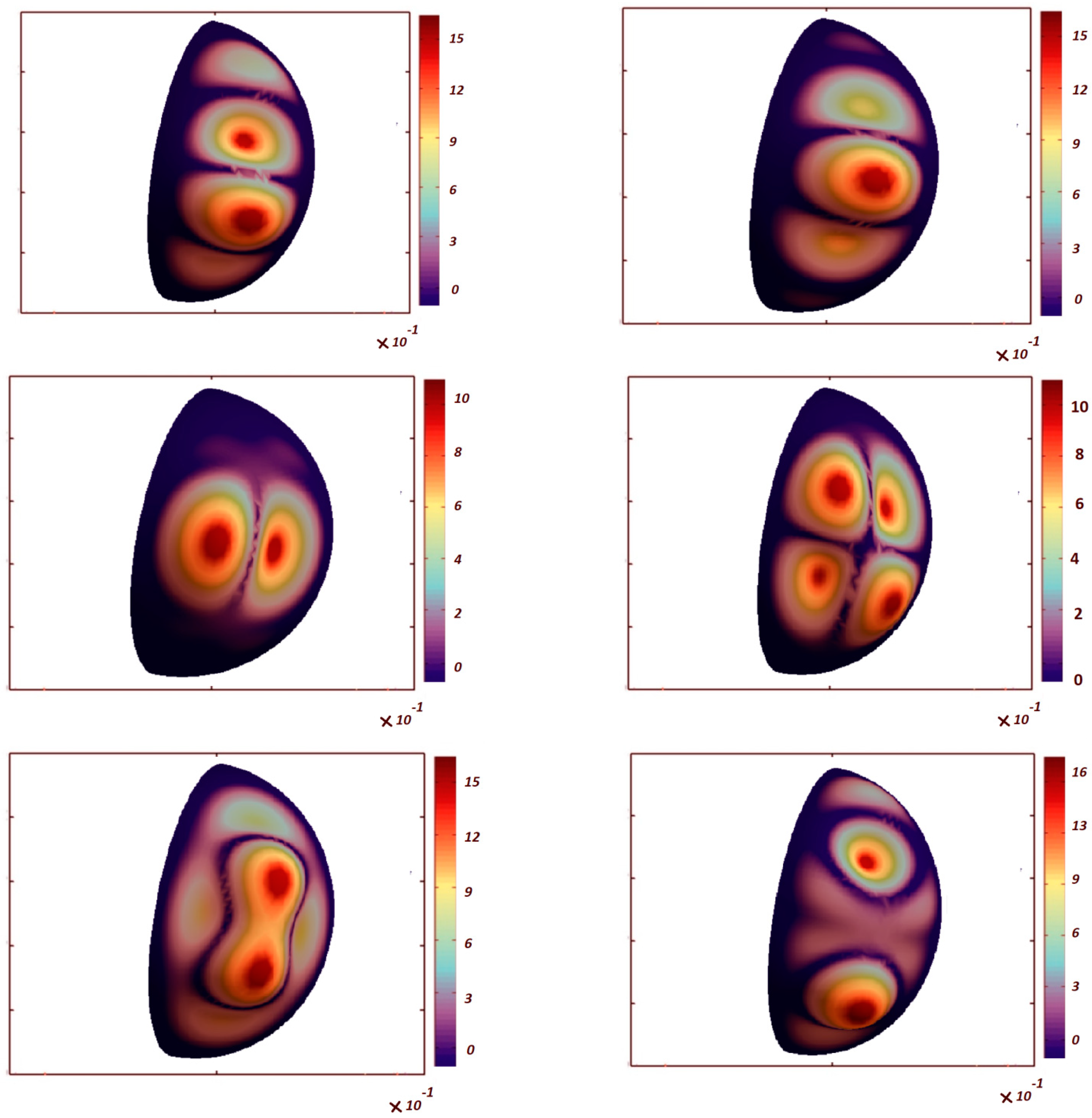
Table 6 shows the effect of the porosity coefficient on the critical buckling loads of FG-GPL, porous spherical shells (PD1, γ = 0.01 wt%, GPLX). When the porosity of the structure increases, the critical buckling load of FG–GPL porous spherical shells decreases, because of the decreased structural stiffness. The comparative evaluation of Table 3, Table 4, Table 5 and Table 6 denotes that the influence of the porosity coefficient on the critical buckling load is lower than the GPL pattern and weight fraction of the nanofiller (its impact is approximately equal to 12.5%). On the other hand, the effects of the GPL pattern, porosity distribution and weight fraction of nanofillers on the critical buckling loads of FG–GPL, porous spherical shells are more pronounced than the porosity coefficient. The first six buckling mode shapes are shown in Figure 3 and Figure 4 for the clamped spherical caps with = 180°, = 180° and 90°, respectively. The figures clearly show that the first two buckling mode shapes and loads for each polar angle of spherical cap are the same. It is also observable that the number of buckling waves increases for higher buckling modes.
5. Concluding Remarks
The present work has studied the buckling responses of spherical caps made of FG porous materials reinforced by GPLs. Three different porosity distributions and five GPL patterns have been considered, along with the shell thickness. The equilibrium equations for the pre-buckling state have been determined according to the linear 3D elasticity theory and the principle of virtual work, whereas the buckling load associated with the problem has been computed according to the nonlinear Green strain field and generalized geometric stiffness concepts. We have studied the influence of the GPL pattern, weight fraction of nanofillers, porosity coefficient, porosity distribution and polar angles on the buckling loads of porous spherical cap made of FG-GPLs. Based on a large systematic investigation, the final remarks can be summarized as follows:
- (a)
- The maximum and minimum buckling loads seem to be reached for GPL-X and GPL-O distributions, respectively.
- (b)
- The maximum and minimum buckling loads belong to the PD1 and PD2 cases, respectively.
- (c)
- The difference between the maximum and minimum critical buckling loads for different porosity distributions is approximately equal to 90%, and the buckling loads of the selected structure increase considerably (approximately of 100%) with an increase in the weight fraction of GPLs.
- (d)
- The effect of the porosity coefficient on the critical buckling load for porous spherical cap shells made of FG-GPLs is lower than the weight fraction of the nanofillers, being approximately equal to 12.5%.
Such results could be useful for designing similar shell members with optimized mechanical properties and structural performances, as required by various engineering applications.
Author Contributions
Conceptualization, Z.Z., Y.W., S.Z., R.D., F.T. and K.A.; Formal analysis, Z.Z., Y.W., S.Z., R.D., F.T. and K.A.; Investigation, Z.Z., Y.W., S.Z. and K.A.; Validation, Z.Z., Y.W., S.Z., R.D., F.T. and K.A.; Writing—Original Draft, Z.Z., Y.W., S.Z. and K.A.; Writing—Review & Editing, R.D. and F.T. All authors have read and agreed to the published version of the manuscript.
Funding
This research received no external funding.
Data Availability Statement
No new data were created or analyzed in this study. Data sharing is not applicable to this article.
Conflicts of Interest
The authors declare no conflict of interest.
References
- Molina, J.-M.; Rodríguez-Guerrero, A.; Louis, E.; Rodríguez-Reinoso, F.; Narciso, J. Porosity Effect on Thermal Properties of Al-12 wt % Si/Graphite Composites. Materials 2017, 10, 177. [Google Scholar] [CrossRef] [Green Version]
- Kiarasi, F.; Babaei, M.; Asemi, K.; Dimitri, R.; Tornabene, F. Free Vibration Analysis of Thick Annular Functionally Graded Plate Integrated with Piezo-Magneto-Electro-Elastic Layers in a Hygrothermal Environment. Appl. Sci. 2022, 12, 10682. [Google Scholar] [CrossRef]
- Narciso, J.; Molina, J.; Rodríguez, A.; Rodríguez-Reinoso, F.; Louis, E. Effects of infiltration pressure on mechanical properties of Al–12Si/graphite composites for piston engines. Compos. Part B Eng. 2016, 91, 441–447. [Google Scholar] [CrossRef] [Green Version]
- Prieto, R.; Molina, J.; Narciso, J.; Louis, E. Thermal conductivity of graphite flakes–SiC particles/metal composites. Compos. Part A Appl. Sci. Manuf. 2011, 42, 1970–1977. [Google Scholar] [CrossRef]
- Zhang, L.; Lai, S.; Wang, C.; Yang, J. DSC regularized Dirac-delta method for dynamic analysis of FG graphene platelet-reinforced porous beams on elastic foundation under a moving load. Compos. Struct. 2020, 255, 112865. [Google Scholar] [CrossRef]
- Priyanka, R.; Twinkle, C.M.; Pitchaimani, J. Stability and dynamic behavior of porous FGM beam: Influence of graded porosity, graphene platelets, and axially varying loads. Eng. Comput. 2021, 38, 4347–4366. [Google Scholar] [CrossRef]
- Binh, C.T.; Quoc, T.H.; Huan, D.T.; Hien, H.T. Vibration characteristics of rotating functionally graded porous beams reinforced by graphene platelets. J. Sci. Technol. Civ. Eng. (STCE) 2021, 15, 29–41. [Google Scholar] [CrossRef]
- Xu, H.; Wang, Y.Q.; Zhang, Y. Free vibration of functionally graded graphene platelet-reinforced porous beams with spinning movement via differential transformation method. Arch. Appl. Mech. 2021, 91, 4817–4834. [Google Scholar] [CrossRef]
- Ganapathi, M.; Anirudh, B.; Anant, C.; Polit, O. Dynamic characteristics of functionally graded graphene reinforced porous nanocomposite curved beams based on trigonometric shear deformation theory with thickness stretch effect. Mech. Adv. Mater. Struct. 2019, 28, 741–752. [Google Scholar] [CrossRef]
- Yas, M.H.; Rahimi, S. Thermal vibration of functionally graded porous nanocomposite beams reinforced by graphene platelets. Appl. Math. Mech. 2020, 41, 1209–1226. [Google Scholar] [CrossRef]
- Safarpour, M.; Rahimi, A.; Alibeigloo, A.; Bisheh, H.; Forooghi, A. Parametric study of three-dimensional bending and frequency of FG-GPLRC porous circular and annular plates on different boundary conditions. Mech. Based Des. Struct. Mach. 2019, 49, 707–737. [Google Scholar] [CrossRef]
- Nguyen, N.V.; Nguyen-Xuan, H.; Lee, D.; Lee, J. A novel computational approach to functionally graded porous plates with graphene platelets reinforcement. Thin-Walled Struct. 2020, 150, 106684. [Google Scholar] [CrossRef]
- Gao, K.; Gao, W.; Chen, D.; Yang, J. Nonlinear free vibration of functionally graded graphene platelets reinforced porous nanocomposite plates resting on elastic foundation. Compos. Struct. 2018, 204, 831–846. [Google Scholar] [CrossRef]
- Saidi, A.R.; Bahaadini, R.; Majidi-Mozafari, K. On vibration and stability analysis of porous plates reinforced by graphene platelets under aerodynamical loading. Compos. Part B Eng. 2019, 164, 778–799. [Google Scholar] [CrossRef]
- Asemi, K.; Babaei, M.; Kiarasi, F. Static, natural frequency and dynamic analyses of functionally graded porous annular sector plates reinforced by graphene platelets. Mech. Based Des. Struct. Mach. 2020, 50, 3853–3881. [Google Scholar] [CrossRef]
- Phan, D.H. Isogeometric Analysis of Functionally-Graded Graphene Platelets Reinforced Porous Nanocomposite Plates Using a Refined Plate Theory. Int. J. Struct. Stab. Dyn. 2020, 2020, 2050076. [Google Scholar] [CrossRef]
- Gao, W.; Qin, Z.; Chu, F. Wave propagation in functionally graded porous plates reinforced with graphene platelets. Aerosp. Sci. Technol. 2020, 102, 105860. [Google Scholar] [CrossRef]
- Zhou, C.; Zhang, Z.; Zhang, J.; Fang, Y.; Tahouneh, V. Vibration analysis of FG porous rectangular plates reinforced by graphene platelets. Steel Compos. Struct. 2020, 34, 215–226. [Google Scholar]
- Teng, M.W.; Wang, Y.Q. Nonlinear forced vibration of simply supported functionally graded porous nanocomposite thin plates reinforced with graphene platelets. Thin-Walled Struct. 2021, 164, 107799. [Google Scholar] [CrossRef]
- Kiarasi, F.; Babaei, M.; Sarvi, P.; Asemi, K.; Hosseini, M.; Omidi Bidgoli, M. A review on functionally graded porous structures reinforced by graphene platelets. J. Comput. Appl. Mech. 2021, 52, 731–750. [Google Scholar]
- Ton-That, H.L.; Nguyen-Van, H.; Chau-Dinh, T. A novel quadrilateral element for analysis of functionally graded porous plates/shells reinforced by graphene platelets. Arch. Appl. Mech. 2021, 91, 2435–2466. [Google Scholar] [CrossRef]
- Ansari, R.; Hassani, R.; Gholami, R.; Rouhi, H. Free vibration analysis of postbuckled arbitrary-shaped FG-GPL-reinforced porous nanocomposite plates. Thin-Walled Struct. 2021, 163, 107701. [Google Scholar] [CrossRef]
- Safarpour, M.; Rahimi, A.R.; Alibeigloo, A. Static and free vibration analysis of graphene platelets reinforced composite truncated conical shell, cylindrical shell, and annular plate using theory of elasticity and DQM. Mech. Based Des. Struct. Mach. 2019, 48, 496–524. [Google Scholar] [CrossRef]
- Bahaadini, R.; Saidi, A.R.; Arabjamaloei, Z.; Ghanbari-Nejad-Parizi, A. Vibration Analysis of Functionally Graded Graphene Reinforced Porous Nanocomposite Shells. Int. J. Appl. Mech. 2019, 11, 1950068. [Google Scholar] [CrossRef]
- Kiarasi, F.; Babaei, M.; Mollaei, S.; Mohammadi, M.; Asemi, K. Free vibration analysis of FG porous joined truncated conical-cylindrical shell reinforced by graphene platelets. Adv. Nanores. 2021, 11, 361–380. [Google Scholar]
- Babaei, M.; Kiarasi, F.; Marashi, S.M.H.; Ebadati, M.; Masoumi, F.; Asemi, K. Stress wave propagation and natural frequency analysis of functionally graded graphene platelet-reinforced porous joined conical–cylindrical–conical shell. Waves Random Complex Media 2021, 1–33. [Google Scholar] [CrossRef]
- Ye, C.; Wang, Y.Q. Nonlinear forced vibration of functionally graded graphene platelet-reinforced metal foam cylindrical shells: Internal resonances. Nonlinear Dyn. 2021, 104, 2051–2069. [Google Scholar] [CrossRef]
- Wang, Y.Q.; Ye, C.; Zu, J.W. Nonlinear vibration of metal foam cylindrical shells reinforced with graphene platelets. Aerosp. Sci. Technol. 2018, 85, 359–370. [Google Scholar] [CrossRef]
- Moradi-Dastjerdi, R.; Behdinan, K. Stress waves in thick porous graphene-reinforced cylinders under thermal gradient environments. Aerosp. Sci. Technol. 2021, 110, 106476. [Google Scholar] [CrossRef]
- Salehi, M.; Gholami, R.; Ansari, R. Analytical solution approach for nonlinear vibration of shear deformable imperfect FG-GPLR porous nanocomposite cylindrical shells. Mech. Based Des. Struct. Mach. 2021, 1–23. [Google Scholar] [CrossRef]
- Nejadi, M.; Mohammadimehr, M.; Mehrabi, M. Free vibration and stability analysis of sandwich pipe by considering porosity and graphene platelet effects on conveying fluid flow. Alex. Eng. J. 2020, 60, 1945–1954. [Google Scholar] [CrossRef]
- Zhou, X.; Wang, Y.; Zhang, W. Vibration and flutter characteristics of GPL-reinforced functionally graded porous cylindrical panels subjected to supersonic flow. Acta Astronaut. 2021, 183, 89–100. [Google Scholar] [CrossRef]
- Ebrahimi, F.; Seyfi, A.; Dabbagh, A.; Tornabene, F. Wave dispersion characteristics of porous graphene platelet-reinforced composite shells. Struct. Eng. Mech. 2019, 71, 99–107. [Google Scholar]
- Pourjabari, A.; Hajilak, Z.E.; Mohammadi, A.; Habibi, M.; Safarpour, H. Effect of Porosity on free and forced vibration characteristics of the GPL reinforcement composite nanostructures. Comput. Math. Appl. 2019, 77, 2608–2626. [Google Scholar] [CrossRef]
- Zhou, Z.; Ni, Y.; Tong, Z.; Zhu, S.; Sun, J.; Xu, X. Accurate nonlinear buckling analysis of functionally graded porous graphene platelet reinforced composite cylindrical shells. Int. J. Mech. Sci. 2018, 151, 537–550. [Google Scholar] [CrossRef]
- Shahgholian-Ghahfarokhi, D.; Rahimi, G.; Khodadadi, A.; Salehipour, H.; Afrand, M. Buckling analyses of FG porous nanocomposite cylindrical shells with graphene platelet reinforcement subjected to uniform external lateral pressure. Mech. Based Des. Struct. Mach. 2020, 49, 1059–1079. [Google Scholar] [CrossRef]
- Shahgholian-Ghahfarokhi, D.; Safarpour, M.; Rahimi, A. Torsional buckling analyses of functionally graded porous nanocomposite cylindrical shells reinforced with graphene platelets (GPLs). Mech. Based Des. Struct. Mach. 2019, 49, 81–102. [Google Scholar] [CrossRef]
- Yang, J.; Chen, D.; Kitipornchai, S. Buckling and free vibration analyses of functionally graded graphene reinforced porous nanocomposite plates based on Chebyshev-Ritz method. Compos. Struct. 2018, 193, 281–294. [Google Scholar] [CrossRef]
- Dong, Y.; He, L.; Wang, L.; Li, Y.; Yang, J. Buckling of spinning functionally graded graphene reinforced porous nanocomposite cylindrical shells: An analytical study. Aerosp. Sci. Technol. 2018, 82–83, 466–478. [Google Scholar] [CrossRef]
- Ansari, R.; Hassani, R.; Gholami, R.; Rouhi, H. Nonlinear bending analysis of arbitrary-shaped porous nanocomposite plates using a novel numerical approach. Int. J. Nonlinear Mech. 2020, 126, 103556. [Google Scholar] [CrossRef]
- Kitipornchai, S.; Chen, D.; Yang, J. Free vibration and elastic buckling of functionally graded porous beams reinforced by graphene platelets. Mater. Des. 2017, 116, 656–665. [Google Scholar] [CrossRef]
- Twinkle, C.M.; Pitchaimani, J. Free vibration and stability of graphene platelet reinforced porous nano-composite cylindrical panel: Influence of grading, porosity and non-uniform edge loads. Eng. Struct. 2021, 230, 111670. [Google Scholar]
- Nguyen, Q.H.; Nguyen, L.B.; Nguyen, H.B.; Nguyen-Xuan, H. A three-variable high order shear deformation theory for isogeometric free vibration, buckling and instability analysis of FG porous plates reinforced by graphene platelets. Compos. Struct. 2020, 245, 112321. [Google Scholar] [CrossRef]
- Anamagh, M.R.; Bediz, B. Free vibration and buckling behavior of functionally graded porous plates reinforced by graphene platelets using spectral Chebyshev approach. Compos. Struct. 2020, 253, 112765. [Google Scholar] [CrossRef]
- Barbaros, I.; Yang, Y.; Safaei, B.; Yang, Z.; Qin, Z.; Asmael, M. State-of-the-art review of fabrication, application, and mechanical properties of functionally graded porous nanocomposite materials. Nanotechnol. Rev. 2022, 11, 321–371. [Google Scholar] [CrossRef]
- Budiansky, B.; Roth, R.S. Axisymmetric Dynamic Buckling of Clamped Shallow Spherical Shells; NASA TND-1510; NASA: Washington, DC, USA, 1962; pp. 597–609.
- Simitses, G.J. Axisymmetric dynamic snap-through buckling of shallow spherical caps. AIAA J. 1967, 5, 1019–1021. [Google Scholar] [CrossRef]
- Kao, R.; Perrone, N. Dynamic buckling of axisymmetic spherical caps with initial imperfection. Comput. Struct. 1978, 9, 463–473. [Google Scholar] [CrossRef]
- Kao, R. Nonlinear dynamic buckling of spherical caps with initial imperfections. Comput. Struct. 1980, 12, 49–63. [Google Scholar] [CrossRef]
- Chao, C.; Lin, I. Static and dynamic snap-through of orthotropic spherical caps. Compos. Struct. 1990, 14, 281–301. [Google Scholar] [CrossRef]
- Alwar, R.; Reddy, B.S. Dynamic buckling of isotropic and orthotropic shallow spherical cap with circular hole. Int. J. Mech. Sci. 1979, 21, 681–688. [Google Scholar] [CrossRef]
- Haboussi, M.; Sankar, A.; Ganapathi, M. Nonlinear axisymmetric dynamic buckling of functionally graded graphene reinforced porous nanocomposite spherical caps. Mech. Adv. Mater. Struct. 2019, 28, 127–140. [Google Scholar] [CrossRef]
- Penna, R.; Feo, L.; Lovisi, G.; Fabbrocino, F. Application of the Higher-Order Hamilton Approach to the Nonlinear Free Vibrations Analysis of Porous FG Nano-Beams in a Hygrothermal Environment Based on a Local/Nonlocal Stress Gradient Model of Elasticity. Nanomaterials 2022, 12, 2098. [Google Scholar] [CrossRef] [PubMed]
- Penna, R.; Feo, L.; Lovisi, G.; Fabbrocino, F. Hygro-Thermal Vibrations of Porous FG Nano-Beams Based on Local/Nonlocal Stress Gradient Theory of Elasticity. Nanomaterials 2021, 11, 910. [Google Scholar] [CrossRef]
- Liu, Y.F.; Wang, Y.Q. Thermo-Electro-Mechanical Vibrations of Porous Functionally Graded Piezoelectric Nanoshells. Nanomaterials 2019, 9, 301. [Google Scholar] [CrossRef] [PubMed] [Green Version]
- Karami, B.; Shahsavari, D.; Janghorban, M.; Dimitri, R.; Tornabene, F. Wave Propagation of Porous Nanoshells. Nanomaterials 2018, 9, 22. [Google Scholar] [CrossRef] [Green Version]
- Kiarasi, F.; Babaei, M.; Asemi, K.; Dimitri, R.; Tornabene, F. Three-Dimensional Buckling Analysis of Functionally Graded Saturated Porous Rectangular Plates under Combined Loading Conditions. Appl. Sci. 2021, 11, 10434. [Google Scholar] [CrossRef]
- Babaei, M.; Asemi, K.; Kiarasi, F. Dynamic analysis of functionally graded rotating thick truncated cone made of saturated porous materials. Thin-Walled Struct. 2021, 164, 107852. [Google Scholar] [CrossRef]
- Arshid, E.; Khorshidvand, A.R. Free vibration analysis of saturated porous FG circular plates integrated with piezoelectric actuators via differential quadrature method. Thin-Walled Struct. 2018, 125, 220–233. [Google Scholar] [CrossRef]
- Babaei, M.; Kiarasi, F.; Tehrani, M.S.; Hamzei, A.; Mohtarami, E.; Asemi, K. Three-dimensional free vibration analysis of functionally graded graphene reinforced composite laminated cylindrical panel. Proc. Inst. Mech. Eng. Part L J. Mater. Des. Appl. 2022, 236, 1501–1514. [Google Scholar] [CrossRef]
- Liu, D. Free Vibration of Functionally Graded Graphene Platelets Reinforced Magnetic Nanocomposite Beams Resting on Elastic Foundation. Nanomaterials 2020, 10, 2193. [Google Scholar] [CrossRef]
- Wang, Y.; Xie, K.; Fu, T.; Shi, C. Bending and Elastic Vibration of a Novel Functionally Graded Polymer Nanocomposite Beam Reinforced by Graphene Nanoplatelets. Nanomaterials 2019, 9, 1690. [Google Scholar] [CrossRef] [PubMed] [Green Version]
- Babaei, M.; Kiarasi, F.; Asemi, K.; Dimitri, R.; Tornabene, F. Transient Thermal Stresses in FG Porous Rotating Truncated Cones Reinforced by Graphene Platelets. Appl. Sci. 2022, 12, 3932. [Google Scholar] [CrossRef]
Figure 1.
Main geometric parameters and assumptions for the spherical cap.

Figure 2.
GPL distributions: (A) symmetric distribution I, (B) symmetric distribution II and (C) uniform distribution and patterns of porosities: (a) GPL-X, (b) GPL-O, (c) GPL-UD, (d) GPL-A, (e) GPL-V.
Figure 2.
GPL distributions: (A) symmetric distribution I, (B) symmetric distribution II and (C) uniform distribution and patterns of porosities: (a) GPL-X, (b) GPL-O, (c) GPL-UD, (d) GPL-A, (e) GPL-V.

Figure 3.
The first six buckling mode shapes of an FG-GPL, porous spherical cap ( = 180°, = 180°, GPL-X, PD1, e0 = 0.4, γ = 0.01 wt%).
Figure 3.
The first six buckling mode shapes of an FG-GPL, porous spherical cap ( = 180°, = 180°, GPL-X, PD1, e0 = 0.4, γ = 0.01 wt%).


Figure 4.
The first six buckling mode shapes of FG-GPL, porous spherical cap ( = 180°, ϕ = 90°, GPL-X, PD1, e0 = 0.4, γ = 0.01 wt%).
Figure 4.
The first six buckling mode shapes of FG-GPL, porous spherical cap ( = 180°, ϕ = 90°, GPL-X, PD1, e0 = 0.4, γ = 0.01 wt%).


Table 1.
Porosity coefficients for different distributions.
| 0.1 | 0.1738 | 0.9361 |
| 0.2 | 0.3442 | 0.8716 |
| 0.3 | 0.5103 | 0.8064 |
| 0.4 | 0.6708 | 0.7404 |
| 0.5 | 0.8231 | 0.6733 |
| 0.6 | 0.9612 | 0.6047 |
Table 2.
Comparison of buckling loads between present study and Ansys Workbench.
| Polar Angle | |||||||
|---|---|---|---|---|---|---|---|
| (Ansys Workbench) | 2.890 | 2.901 | 2.990 | 3.001 | 3.012 | 3.078 | |
| 180° | (Present) | 2.908 | 2.924 | 3.008 | 3.021 | 3.033 | 3.132 |
| (Ansys Workbench) | 1.861 | 1.867 | 2.110 | 2.101 | 2.159 | 2.299 | |
| 90° | (Present) | 1.873 | 1.875 | 2.180 | 2.211 | 2.222 | 2.320 |
Table 3.
Buckling loads (GPa) of FG-GPL, porous spherical caps for various polar angles and GPL patterns (PD3, e0 = 0.2, γ = 0.01 wt%).
Table 3.
Buckling loads (GPa) of FG-GPL, porous spherical caps for various polar angles and GPL patterns (PD3, e0 = 0.2, γ = 0.01 wt%).
| GPL Pattern | λ1 | λ2 | λ3 | λ4 | λ5 | λ6 | |
|---|---|---|---|---|---|---|---|
| 90° | 3.174 | 3.174 | 3.670 | 3.775 | 3.778 | 3.939 | |
| GPL-X | 180° | 4.450 | 4.462 | 4.572 | 4.600 | 4.617 | 4.798 |
| 90° | 1.898 | 1.901 | 2.227 | 2.254 | 2.264 | 2.354 | |
| GPL-A | 180° | 2.914 | 2.925 | 2.997 | 3.009 | 3.018 | 3.109 |
| 90° | 1.885 | 1.888 | 2.212 | 2.238 | 2.248 | 2.336 | |
| GPL-V | 180° | 2.906 | 2.917 | 2.988 | 3.001 | 3.009 | 3.098 |
| 90° | 1.653 | 1.657 | 1.949 | 1.950 | 1.958 | 2.018 | |
| GPL-O | 180° | 2.731 | 2.747 | 2.801 | 2.821 | 2.824 | 2.894 |
| 90° | 1.903 | 1.906 | 2.233 | 2.259 | 2.270 | 2.359 | |
| GPL-UD | 180° | 2.926 | 2.937 | 3.009 | 3.022 | 3.030 | 3.121 |
Table 4.
Buckling loads (GPa) of FG-GPL, porous spherical caps for various polar angles and porosity distributions (GPLX, e0 = 0.4, γ = 0.01wt%).
Table 4.
Buckling loads (GPa) of FG-GPL, porous spherical caps for various polar angles and porosity distributions (GPLX, e0 = 0.4, γ = 0.01wt%).
| Porosity Distribution | λ1 | λ2 | λ3 | λ4 | λ5 | λ6 | |
|---|---|---|---|---|---|---|---|
| 90° | 2.842 | 2.842 | 3.268 | 3.346 | 3.359 | 3.473 | |
| PD1 | 180° | 3.964 | 3.974 | 4.076 | 4.092 | 4.111 | 4.259 |
| 90° | 1.581 | 1.584 | 1.862 | 1.863 | 1.870 | 1.926 | |
| PD2 | 180° | 2.613 | 2.632 | 2.684 | 2.703 | 2.707 | 2.774 |
| 90° | 2.249 | 2.249 | 2.607 | 2.677 | 2.683 | 2.799 | |
| PD3 | 180° | 3.191 | 3.199 | 3.280 | 3.297 | 3.310 | 3.434 |
Table 5.
Buckling loads (GPa) of an FG-GPL, porous spherical cap for various polar angle and weight fractions of GPL nano-fillers (PD1, e0 = 0.5, GPLX).
Table 5.
Buckling loads (GPa) of an FG-GPL, porous spherical cap for various polar angle and weight fractions of GPL nano-fillers (PD1, e0 = 0.5, GPLX).
| Weight Fraction of Nano-Fillers (%wt) | λ1 | λ2 | λ3 | λ4 | λ5 | λ6 | |
|---|---|---|---|---|---|---|---|
| 90° | 1.458 | 1.459 | 1.696 | 1.737 | 1.744 | 1.819 | |
| 0% | 180° | 2.102 | 2.107 | 2.162 | 2.171 | 2.180 | 2.258 |
| 90° | 2.191 | 2.191 | 2.528 | 2.601 | 2.602 | 2.710 | |
| 0.5% | 180° | 3.048 | 3.056 | 3.130 | 3.151 | 3.163 | 3.290 |
| 90° | 2.744 | 2.746 | 3.187 | 3.261 | 3.268 | 3.403 | |
| 1% | 180° | 3.927 | 3.940 | 4.032 | 4.062 | 4.076 | 4.246 |
Table 6.
Buckling loads (GPa) of FG-GPL, porous spherical caps for various polar angles and porosity coefficients (PD1, γ = 0.01 wt%, GPLX).
Table 6.
Buckling loads (GPa) of FG-GPL, porous spherical caps for various polar angles and porosity coefficients (PD1, γ = 0.01 wt%, GPLX).
| λ1 | λ2 | λ3 | λ4 | λ5 | λ6 | ||
|---|---|---|---|---|---|---|---|
| 90° | 3.262 | 3.262 | 3.780 | 3.881 | 3.889 | 4.055 | |
| 0.2 | 180° | 4.626 | 4.635 | 4.752 | 4.777 | 4.794 | 4.975 |
| 90° | 2.842 | 2.842 | 3.268 | 3.346 | 3.359 | 3.473 | |
| 0.4 | 180° | 3.964 | 3.974 | 4.076 | 4.092 | 4.111 | 4.259 |
| 90° | 2.744 | 2.746 | 3.187 | 3.261 | 3.268 | 3.403 | |
| 0.5 | 180° | 3.927 | 3.940 | 4.032 | 4.062 | 4.076 | 4.246 |
Disclaimer/Publisher’s Note: The statements, opinions and data contained in all publications are solely those of the individual author(s) and contributor(s) and not of MDPI and/or the editor(s). MDPI and/or the editor(s) disclaim responsibility for any injury to people or property resulting from any ideas, methods, instructions or products referred to in the content. |
© 2023 by the authors. Licensee MDPI, Basel, Switzerland. This article is an open access article distributed under the terms and conditions of the Creative Commons Attribution (CC BY) license (https://creativecommons.org/licenses/by/4.0/).
Share and Cite
MDPI and ACS Style
Zhou, Z.; Wang, Y.; Zhang, S.; Dimitri, R.; Tornabene, F.; Asemi, K. Numerical Study on the Buckling Behavior of FG Porous Spherical Caps Reinforced by Graphene Platelets. Nanomaterials 2023, 13, 1205. https://doi.org/10.3390/nano13071205
AMA Style
Zhou Z, Wang Y, Zhang S, Dimitri R, Tornabene F, Asemi K. Numerical Study on the Buckling Behavior of FG Porous Spherical Caps Reinforced by Graphene Platelets. Nanomaterials. 2023; 13(7):1205. https://doi.org/10.3390/nano13071205
Chicago/Turabian StyleZhou, Zhimin, Yun Wang, Suying Zhang, Rossana Dimitri, Francesco Tornabene, and Kamran Asemi. 2023. "Numerical Study on the Buckling Behavior of FG Porous Spherical Caps Reinforced by Graphene Platelets" Nanomaterials 13, no. 7: 1205. https://doi.org/10.3390/nano13071205
Note that from the first issue of 2016, this journal uses article numbers instead of page numbers. See further details here.