Article

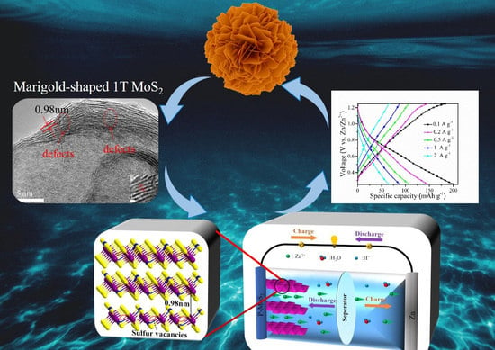
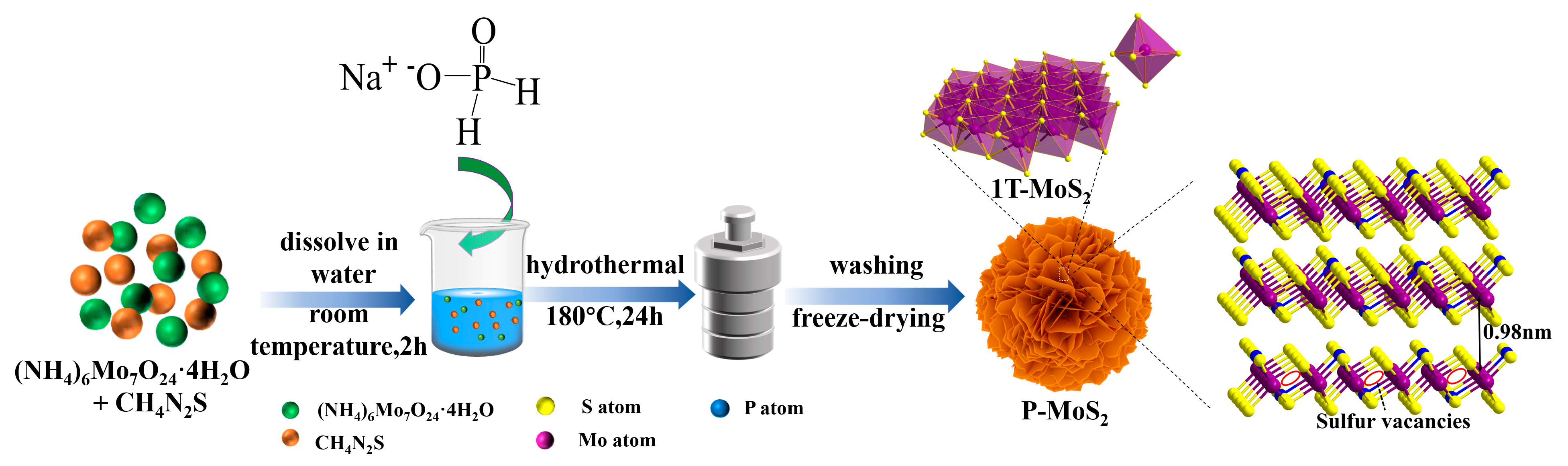
Enlarged Interlayer Spacing of Marigold-Shaped 1T-MoS2 with Sulfur Vacancies via Oxygen-Assisted Phosphorus Embedding for Rechargeable Zinc-Ion Batteries

College of Science & Ministry-Province Jointly-Constructed Cultivation Base for State Key Laboratory of Processing for Mom-Ferrous Metal and Featured Materials & Key Lab. of Nonferrous Materials and New Processing Technology & Network and Information Center, Guilin University of Technology, Guilin 541004, China
*
Authors to whom correspondence should be addressed.
Nanomaterials 2023, 13(7), 1185; https://doi.org/10.3390/nano13071185
Submission received: 26 February 2023 / Revised: 22 March 2023 / Accepted: 23 March 2023 / Published: 27 March 2023
(This article belongs to the Special Issue Advanced 2D Materials for Emerging Application)

Abstract

:
Structural unsteadiness and sluggish diffusion of divalent zinc cations in cathodes during cycling severely limit further applications of MoS2 for rechargeable aqueous zinc-ion batteries (ZIBs). To circumvent these hurdles, herein, phosphorus (P) atom embedded three-dimensional marigold-shaped 1T MoS2 structures combined with the design of S vacancies (Sv) are synthesized via the oxygen-assisted solvent heat method. The oxygen-assisted method is utilized to aid the P-embedding into the MoS2 crystal, which can expand the interlayer spacing of P-MoS2 and strengthen Zn2+ intercalation/deintercalation. Meanwhile, the three-dimensional marigold-shaped structure with 1T phase retains the internal free space, can adapt to the volume change during charge and discharge, and improve the overall conductivity. Moreover, Sv is not only conducive to the formation of rich active sites to diffuse electrons and Zn2+ but also improves the storage capacity of Zn2+. The electrochemical results show that P-MoS2 can reach a high specific capacity of 249 mAh g−1 at 0.1 A g−1. The capacity remains at 102 mAh g−1 after 3260 cycles at a current of 0.5 A g−1, showing excellent electrochemical performance for Zn2+ ion storage. This research provides a more efficient method of P atom embedded MoS2-based electrodes and will heighten our comprehension of developing cathodes for the ZIBs.

Graphical Abstract

1. Introduction

Due to the distinct characteristics of zinc metal, such as high theoretical capacity (820 mAh g−1), low redox potential (−0.76 V concerning standard hydrogen electrodes), nontoxicity, low cost, and intrinsic safety, as well as high reversibility in aqueous electrolytes, ZIBs hold promising potential for large-scale energy storage [1,2,3,4]. However, Zn2+ in aqueous solution is hard to intercalate between layers because it exists as hydrated zinc ions ([Zn(H2O)6]2+) with a size of 0.404 nm~0.43 nm, making ([Zn(H2O)6]2+) intercalation and deintercalation put forward higher requirements on the interlayer spacing and other properties of the cathode material [5,6,7]. In addition, divalent Zn2+ usually exhibits strong electrostatic interactions with the host lattice, inhibiting the diffusion process of Zn2+, resulting in few cathode materials available for ZIBs, which are mainly confined to manganese-based materials, vanadium-based materials, and Prussian blue [8,9,10]. Therefore, the sluggish intercalation dynamics of divalent Zn2+ enable the search for appropriate cathode materials to be very important for the development and application of ZIBs.
Molybdenum disulfide (MoS2) is a typical layered transition metal sulfide, and the covalently bonded S-Mo-S layers are stacked together by weak van der Waals forces, which is conducive to the intercalation of foreign guests [11,12,13,14]. Unfortunately, due to the strong electrostatic interaction between inserted Zn2+ with a large hydrated radius (4.3 Å) and host structures, Zn2+ is challenging to intercalate/deintercalate from the host frame, greatly affecting the reversible capability and rate characteristic of MoS2 as cathodes arousing from its smaller layer spacing and the large inert base with fewer active sites [15,16,17,18]. Moreover, MoS2 also has problems such as poor conductivity, poor hydrophilicity, agglomeration, and volume expansion, which limits the application of MoS2 in ZIBs. Therefore, some pioneering efforts, including introducing phase transition engineering and tailoring nanostructures, have been made to improve the Zn2+ storage capability of MoS2 cathodes [19,20,21,22]. One available strategy to resolve such challenges is to intercalate foreign elements into MoS2 to enlarge layer spacing [15,23,24]. Experimental and calculation results indicate that P dopants could not only modify the surface electronic state of MoS2 and increase its inherent conductivity but also lead to MoS2 expansion and induce a partial phase transition of MoS2 from hydrophobic (2H phase) to hydrophilic (1T phase); the 1T-MoS2 has lower Zn diffusion energy barriers [25]. However, due to the spontaneous formation of MoP, resulting in P atom doping is inherently difficult and has lower P content [26,27]. Despite substantial achievements having been made, P-embedding 1T-MoS2 to achieve extended layer spacing for enhancing the ability of Zn2+ intercalates/deintercalates is very necessary, thus requiring a facile method.
Additionally, vacancy engineering has been in the spotlight as a feasible strategy to enhance the zinc ions storage capability considerably. Especially based on previous reports [28], sulfur vacancies can provide abundant active sites as additional ion storage sites for Zn2+ as well as offer a fast electrochemical response. For example, Hu et al. [29] developed a few-layered MoS2 anchored on an N-doped carbon flower with Sv as anode material for sodium-ion batteries, exhibiting excellent performance. Wang et al. [30] improved the performance of hydrogen evolution reaction (HER) by regulating the S-vacancy distribution and concentration in MoS2. Xu et al. reported that the preparation of defect-rich MoS2 accelerated the diffusion kinetics of Zn2+ to the active center [31]. Therefore, the rational S vacancy modulation strategy is essential to improve the reaction kinetics of Zn2+ for realizing its application in ZIBs.
Herein, an oxygen-assisted(O) strategy is used to aid the P-embedding into the MoS2 crystal; the MoS2 layer spacing is expanded, and the marigold-shaped 1T-MoS2 nanosheets with rich S vacancies are prepared. In this process, oxygen played a key role in aiding the successful embedding of P into the lattice of 1T-MoS2. The intercalation of P in MoS2 achieves the desired effect, significantly enlarging MoS2 interlayers (from 0.62 to 0.98 nm) and enhancing hydrophilicity. In addition, these S vacancies defects as active sites can make it easier for Zn2+ adsorption and desorption. The synergistic effect of P-embedding induced and extended the marigold-shaped 1T-MoS2 layer spacing and caused the Sv to form an active center in the basal plane of MoS2, effectively reducing the Zn2+ diffusion resistance. It provides an easier channel for the insertion of [Zn(H2O)6]2+, resulting in rapid reaction kinetics. As expected, the P-MoS2 electrode achieves a remarkably high capability of 249 mAh g−1 at 0.1 A g−1, which is five times higher than the specific capacity of pristine MoS2. In comparison to the pristine P-MoS2 counterpart with minimal capacity delivery, P-MoS2 can achieve a high reversible capacity of 105 mAh g−1 at 0.5 A g−1 with 3260 cycles and excellent capacity retention of 70 mAh g −1 at 1 A g−1. This study will provide more efficient avenues for investigating more electrode materials with poor intercalation kinetics in ZIBs.

2. Methods

2.1. Experimental Section

Synthesis of P-MoS2: In a representative procedure, 1 mmol (1236 mg) ammonium molybdate tetrahydrate ((NH4)6Mo7O24·4H2O, AR) and 30 mmol (2284 mg) thiourea (CH4N2S, AR) were added into 35 mL deionized water on the basis of a beforehand report with slight adjustment [32]. After being stirred for 30 min, an amount of sodium hypophosphite monohydrate (NaH2PO2·4H2O, AR, 400 mg) was dissolved into a mixed solution with magnetic stirring for 2 h. Then, the precursor solution was heated to 180 °C for 24 h in a 50 mL Teflon-lined stainless steel autoclave. After cooling the reaction system to air temperature, which was collected by centrifugation, cleaned multiple times with water, and then dried at 80 °C. As a contrast, pristine MoS2 was also prepared without NaH2PO2·4H2O following a similar synthetic route.

2.2. Material Characterizations

The morphology of materials was evaluated with a scanning electron microscope (SEM, Hitachi S-4800, Tokyo, Japan) and a transmission electron microscope (TEM, Tecnai G2 20 TWIN, FEI, Hillsboro, OR, USA). An energy dispersive spectrometer (EDS S-00123, USA) connected to the SEM was used to study the elemental composition and elemental analyses of the composites. At −196 °C, N2 adsorption/desorption isotherms were measured with an automated SSA and porosity analyzer (asap2460). Brunauer–Emmett–Teller (BET) and Barrett–Joyner–Halenda (BJH) adsorption techniques were used to determine the SSA and mesopore size distribution of each sample. All samples’ crystal phases and compositions were determined using X-ray diffraction (XRD, MiniFlex-600, Rigaku, Tokyo, Japan) and X-ray photoelectron spectroscopy (XPS, Thermo Scientific K-Alpha, Waltham, MA, USA). Raman spectra at 532 nm were measured with a Horiba Scientific LabRAM HR Evolution Raman spectrometer. The TGA/DTA was tested by thermogravimetric analysis equipment (SDT Q600, USA) from room temperature to 750 °C at a heating rate of 10 °C/min. A hydrophilicity test was measured using a contact angle test device (Dataphysics OCA20, Filderstadt, Germany).

2.3. Electrochemical Characterization

Zn served as the anode, glass fiber membrane served as diaphragms, and 3 M Zn(CF3SO3)2 served as the electrolyte in CR2016-type coin cells used to investigate the Zn2+ storage properties of P-MoS2. To manufacture the working electrode, P-MoS2 (70 weight percent), super p carbon (20 weight percent), and polyvinylidene fluoride (10 weight percent) were thoroughly blended in N-methyl-2-pyrrolidone for 15 min. Finally, the aforementioned slurry was distributed over a clean stainless steel mesh and dried for 24 h at 60 °C. On a Neware battery tester (CT4008), galvanostatic charge/discharge measurements and galvanostatic intermittent titration technique (GITT) experiments were carried out continuously between 0.25 and 1.25 V (vs. Zn/Zn2+). An electrochemical workstation was used for the cyclic voltammetry (CV) and electrochemical impedance spectroscopy (EIS) experiments (CHI-660D). When the batteries were completely charged, impedance measurements were taken (zinc extraction). At room temperature, all tests were conducteddw.

3. Results and Discussion

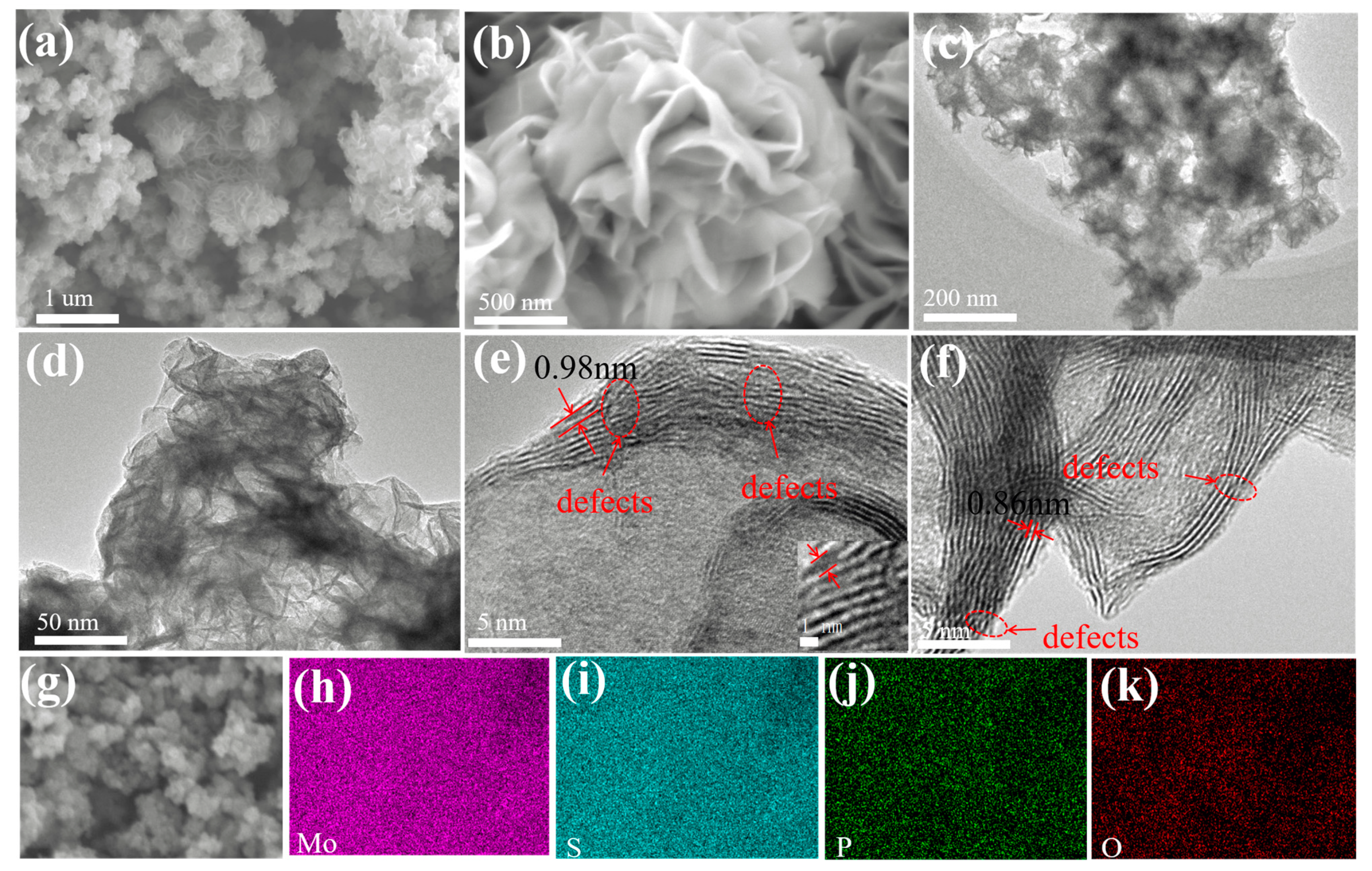
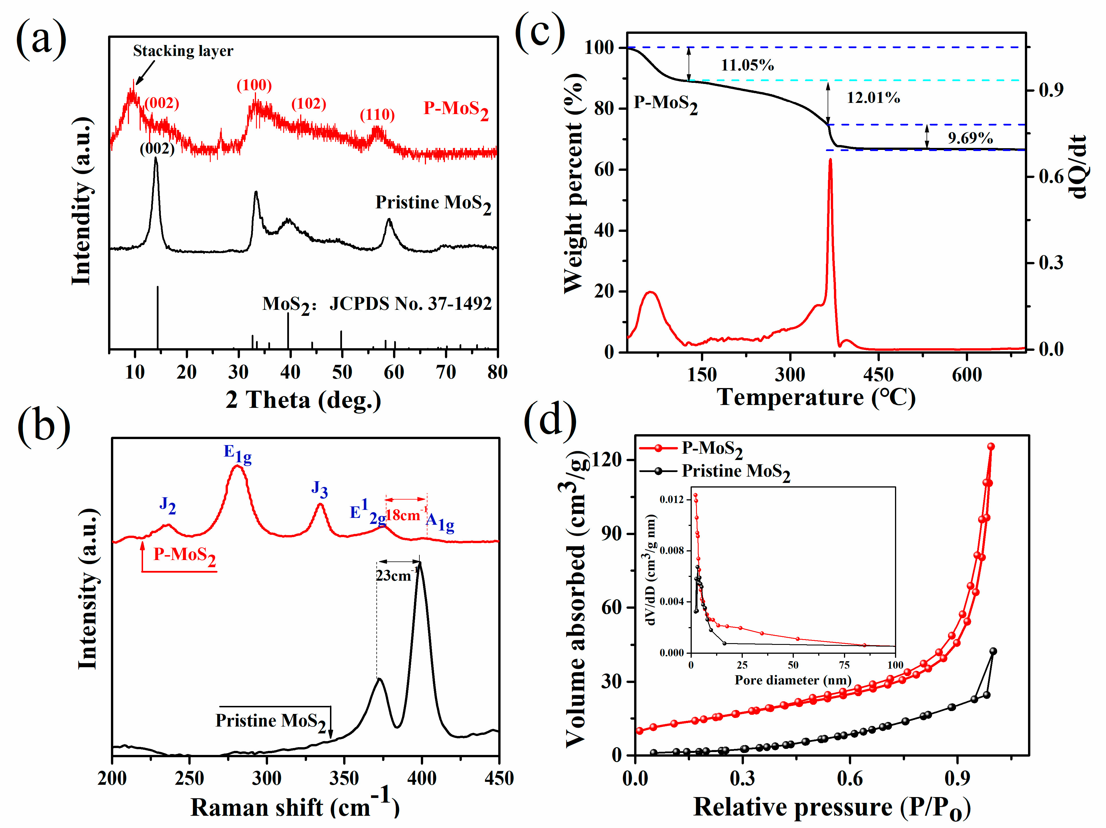
3.1. Composition and Structure

Figure 1 depicts the synthesis process of P-MoS2 and pristine MoS2. The phosphorus embedded three-dimensional marigold 1T MoS2 was obtained by controlling the crystallization process. In a nutshell, an oxygen-rich atmosphere plays a vital role in decreasing the formation energy of P-embedding in MoS2 [26]. The reaction process becomes more inadequate as the synthesis temperature decreases, resulting in the leftover oxygen inherited from the molybdate precursor, thus realizing the oxygen-rich atmosphere [32]. Additionally, most of the Mo4+ ions form ionic bonds with S2−, which are self-assembled in the form of nanocrystals connected into three-dimensional marigold-shaped structures. Excess thiourea could be adsorbed on the surfaces of initial nanocrystallites and impede the formation of orientated crystals, which results in abundant Sv being produced amid the flat structure [33]. The SEM and TEM were utilized to explore the morphology evolution of as-prepared P-MoS2 further. As shown in Figure 2a,b, the SEM of P-MoS2 displays the magnificent marigold structure with an internal diameter of almost 1 µm, which was self-assembled from curved thickness nanosheets with transverse dimensions of 400–500 nm. In comparison, pristine MoS2 has a rather formidable nanosheet microstructure, which is much larger in transverse size (diameter almost 4–5 µm) and displays severe aggregation in the absence of a well-tuned morphology (Figure S1). The relatively smaller size of the beautiful marigold structure should help to shorten the Zn2+ diffusion duration. The uneven nanostructure of P-MoS2 with evident ripples and bending wrinkles is depicted in TEM images (Figure 2c,d), in which nanosheets are haphazardly joined and formed into three-dimensional structures. The TEM images in Figure 1e,f reveal a distinct lattice structure with some disorder and abundance of Sv (Figure S2), resulting in an incomplete lattice that may accommodate a host of unsaturated S atoms as active sites. Furthermore, the TEM images reveal that dozens of pristine MoS2 layers are heavily stacked together with an interlayer spacing of 0.62 nm (Figure S3), whereas the stacking of the P-MoS2 layers is significantly relieved with the interlayer distance strikingly expanding to 0.98 (Figure S4) and 0.86 nm. The results show that P-embedding can enlarge the layer spacing of P-MoS2, which is advantageous to strengthen Zn2+ intercalates/deintercalates. Figure 2h–k displays the mapping images of P-MoS2, which expressly demonstrate that Mo, O, S, and P elements are distributed uniformly. Meanwhile, Figure S5 shows the elemental content of P-MoS2.
The structural information of the two obtained samples was studied by X-ray diffraction (XRD) analysis (Figure 3a). Compared with the highly crystalline pristine MoS2 in the 2H-MoS2 phase (JCPDS card number 37–1492), all peaks of the P-MoS2 are broadened due to nanoscale effects and crystal structural defects. The weakening of the (002) diffraction peak of P-MoS2 indicates a low stacking height along this direction [34,35]. Meanwhile, the (002) peak of P-MoS2 slightly shifts to a lower angle (14.2° → 13.96°), indicating the formation of sulfur vacancies in MoS2 [36,37]. In addition, a new peak appeared at 9.8°, which is related to the presence of P, leading to the formation of a stacking layer, thus extending the c-axis of MoS2. According to Bragg’s law, the lattice spacing of the stacking layer at 9.8° is consistent with the spacing in TEM. Due to P’s larger atomic radius than S, P atoms were introduced into the MoS2 matrix, causing the lattice to expand and contributing to the widening of interlayer spacing [25,38,39]. Figure 3b exhibits the Raman spectra of P-MoS2. Three typical Raman scattering peaks at 280 cm−1 (E1g), 234 (J2) cm−1, and 334 cm−1 (J3) are attributed to the octahedral coordination of metal 1T-MoS2 [40,41,42]. P-MoS2 exhibits two typical characteristic peaks at 376 cm−1 and 394 cm−1, corresponding to the in-plane (E12g) and out-of-plane (A1g) modes of 2H MoS2, which are clearly distinct from pristine MoS2. The distance between the E12g and A1g peaks is 18 cm−1 for P-MoS2 and 23 cm−1 for bulk MoS2. Thus, the moving peak of A1g might represent the substantial out-of-plane vibration, indicating that the decreased van der Waals force, together with the enlarged interlayer spacing of MoS2 caused by P-embedding, is favourable for Zn2+ movement and storage [5,43]. The weaker intensity of the E12g peak in P-MoS2 is weaker compared to other samples, thereby proving the presence of Sv in the crystal structure [44].
The TGA-DTA results for the P-MoS2 shown in Figure 3c show the initial mass loss of 11.05 wt% at 135 °C due to surface-adsorbed water evaporation. The mass loss of 12.01 wt% between 135 and 350 °C corresponds to the water loss integrated into the crystal structure, implying that the enlarged layer spacing of P-MoS2 is probably caused by water insertion [45]. The additional weight loss of 9.69% over 350 °C may be caused by O atoms, which are utilized to aid P atoms embedded in the MoS2 structure, with the unsaturated S atoms resulting In the reaction 2MoS2 + 7O2 → 2MoO3 + 4SO2 [46,47]. The first derivative curve of the related DTA curve shows a visible endothermic peak at 350 °C. This peak is caused by the transformation of the crystal structure of MoS2, which is confirmed by XRD analysis. Moreover, the cumulative pore volume and BET surface area of P-MoS2 and pristine MoS2 were also measured. As shown in Figure 3d, P-MoS2 and pristine MoS2 exhibited typical type IV isotherms with hysteresis loops, indicating mesopores between MoS2 nanosheets. Nevertheless, the hysteresis of P-MoS2 starts at a lower pressure region (P/P0 ≈ 0.5) than that of pristine MoS2 (P/P0 ≈ 1), showing their different porous nature. Furthermore, the wide hysteresis of P-MoS2 indicates its increase in porosity. According to the pore volume–pore size distribution curve, P-MoS2 has more abundant mesoporous structures, which is conducive to electron transport. The increased specific surface area of P-MoS2 is 51.572 m2 g−1, which is significantly more than pristine MoS2 (11 m2 g−1). The increased specific surface area improves the interaction between the material’s exposed active sites and the electrolyte, which favors increasing the number of active sites for Zn2+ storage. These results clearly show that the P-embedding strategy can greatly increase the surface area and pore volume of MoS2. To evaluate the hydrophilicity of P-MoS2, we performed a contact angle test. Water contact angles of P-MoS2 drop from 54.46° to 38.8° (Figure S6), suggesting improved hydrophilicity and beneficial to the diffusion of Zn2+ [6].
X-ray photoelectron spectroscopy (XPS) reveals detailed valence states and chemical contents of manufactured materials. The survey XPS spectra for P-MoS2 and is displayed in Figure S7. As shown in Figure 4a, the XPS spectra of the Mo 3d scan contain two sets of doublet peaks (228.55 and 231.76 eV; 229.5 and 232.75 eV), which belong to Mo 3d5/2 and Mo 3d3/2 of Mo4+ for 1T-MoS2 and 2H-MoS2 [19,48,49]. This suggests the coexistence of 2H and 1T in P-MoS2, which is compatible with Raman data. Similarly, differences can be observed in the S 2p spectra in Figure 4b, where peaks at 161.4 (S 3d3/2 of S2−) and 162.7 eV (S 3d1/2 of S2−) attributed to 1T MoS2, while peaks at 162.0 and 163.1 eV ascribed to 2H-MoS2 [49]. After fitting S 2p spectrum, an extra peak can be seen at 164.19 eV, according to the relevant literature, ascribed to the edge S [50]. Furthermore, using deconvolutions of Mo 3d, the proportion of 1T is estimated at 53% (Table S1), which is equivalent to the product obtained from chemical exfoliation [21]. Meanwhile, the existence of the O 1s signal offers conclusive proof of oxygen-assisted P-embedding in P-MoS2 (Figure 4c). It can be deconvoluted into three peaks at 530.42, 531.94, and 533.44 eV, which is ascribed to the P-O bond, Mo-O bond, and adsorbed water, respectively. The analysis shows that oxygen plays an auxiliary role in P-embedding and can also make P-MoS2 form a three-dimensional beautiful marigold structure in a bonding manner. P 2p signals were detected at 134.02, 130.99, and 130.06 eV (Figure 4d), confirming the existence of P. The dominant P signal at 134.6 eV can be allocated to the PO43− species, whereas the remaining two should be attributed to Mo-P, indicating that P atoms are embedded in the MoS2 lattice [44,51]. Furthermore, elemental composition analysis reveals that the Mo/S ratio is around 1:1.73 (Table S2), which is much lower than the 1:1.95 for MoS2 by XPS. This finding implies that P-MoS2 has a substantial number of S vacancies [5,20,45].

3.2. Electrochemical Performance of Aqueous Zn-Ion Batteries and Kinetic

To investigate the Zn2+ storage capacity of the prepared samples as stand-alone cathodes for AZIBs, CR2016 coin cells were manufactured in the air environment (see the experimental section for details). Cyclic voltammetry (CV) curves in a voltage window of 0.25 to 1.25 V of 0.1 mV s−1 are shown in Figure 5a,b. In contrast to pristine MoS2, P-MoS2 has two redox peaks: the cathodic peak at 0.65 V linked to Zn2+ insertion (possibly overlapping or merging with the reduction in Mo6+/Mo4+) and an anodic peak at 0.98 V is associated to Zn2+ inlay removal [23]. Furthermore, the second and third CV cycles of the two electrodes practically coincide, showing high reversibility. Surprisingly, the peak area of P-MoS2 is considerably larger than that of pristine MoS2, showing that the enlarged layer spacing and Sv can significantly boost volume capacity. The P-MoS2 charge/discharge (CD) curves are comparable with the CV data (Figure 5c), which shows an intercalation plateau of P-MoS2 approximately 0.6 V. In addition, the specific capacity of P-MoS2 is 249 mA h g−1, which is more than five times that of pristine MoS2 (50 mA h g−1), significantly better than the well-known Zn2+ intercalation host, i.e., the Chevrel Phase Mo6S8 (60 mA h g−1 at 0.06 A g−1) [52,53]. Meanwhile, the capacity of several modified MoS2 materials is compared at 0.1 A g−1 in Table S3. Figure 5d shows display ratio capability with the volumes of P-MoS2, which are 249, 158, 125, 97, and 75 mAh g−1 at 0.1, 0.2, 0.5, 1, and 2 A g−1, respectively, and Figure 5e shows the charge/discharge curves of the first cycle capacity. P-MoS2 capacitance achieves 143 mAh g−1 (91% capacity retention) when it reaches 0.2 A g−1. These hint at the excellent rate characteristic and rapid dynamics of P-MoS2. In contrast, pristine MoS2 offers rather low capacities (0–45 mAh g−1) at a variety of current densities. P-MoS2 demonstrates a consistent capacity of 70 mAh g−1 after 200 cycles at 1 A g−1 to further illustrate its outstanding working life (Figure 5f). The stability was further investigated at 0.5 A g−1 in Figure 5g.
P-MoS2 maintains a capacity of 102 mAh g−1 after 3260 cycles, achieving capacity retention of 70%, with the efficiency of the electrode being close to 100%. However, the cycling stability of the P-MoS2 electrode seems rather poor after 2000 cycles, which is attributed to the irreversible structural damage, volume changes, and unstable 1T phase during the continuous charging and discharging process [54,55]. In comparison, pristine MoS2 has almost zero capacity, which is related to its poor conductivity and unstable structure [16,23].
The results show that P-MoS2 outperforms pristine MoS2 in terms of reversible capacity, cycle stability, and rate capacity. To better understand the electrochemical reaction behavior of the P-MoS2 electrode, CV curves at varied scan speeds (0.1–1.0 mV s−1) are tested (Figure 6a and Figure S8). The oxidation peak gradually shifted toward high potential with an increasing scan rate, and the reduction peak shifted toward low potential because the electrode polarization broadened at a high scan rate. Whether pseudocapacitive behavior is present or absent depends on the kinetic equation of the reaction:
i = a v b
In between, i is the peak current, the unit is A, v is the sweep speed, the unit is mV/s, a and b are the adjustment parameters, and b is the slope value of the log (i) vs. log (b) graph. In particular, b = 0.5 indicates that the discharge-specific capacity belongs to the diffusion process control, and b = 1 implies the pseudocapacitance control. When b is between 0.5–1, there is both diffusion and pseudocapacitance behavior [56]. Obviously, Figure 6b indicates the b-values of peak 1 and peak 2, which are 0.76 and 0.70, showing that the redox reaction of the P-MoS2 electrode consists of diffusion and capacitive processes. Additionally, the capacitive contribution and diffusion contributions of P-MoS2 may be evaluated based on the equation proposed by Dunn [57,58]:
i ( V ) = k 1 v + k 2 v 1 / 2
i ( V ) / v 1 / 2 = k 1 v 1 / 2
At a certain voltage (v), i is the total current response, where k 2 v 1 / 2 and k 1 v are diffusion-controlled and capacitance-dominated contributions. Figure 6c–e reveals the respective contribution rates at different scan rates. Notably, the capacitive contribution increases from 21.7% at 0.1 mV s−1 to 50.1% at 1 mV s−1. The pseudocapacitance effect is slowly dominant, indicating that the surface reaction is faster than the internal diffusion reaction, which accelerates the intercalation and extraction of Zn2+ in the material. Moreover, the diffusion characteristics of P-MoS2 are more obvious, which can be attributed to the marigold-shaped structure and wide layer spacing [59]. The impedance of P-MoS2 and pristine MoS2 is evaluated by EIS, as shown in Figure 6f. The magnitude of the charge transfer resistance is reflected in the semicircle radius of the high-frequency zone (Rct, Table S4). Clearly, results show that the charge transfer impedance of P-MoS2 is measured at 42.82 Ω, which is lower than the pristine MoS2 under the same conditions. In addition, Rcts of pristine MoS2 are markedly over 180 Ω, indicating that expanded layer spacing and S vacancies improve charge-transfer dynamics. Because of the activation of the active material, the charge transfer impedance of P-MoS2 was lowered during the first ten cycles.
To examine the solid-state diffusion kinetics of Zn2+ intercalation in P-MoS2, we investigated GITT, which has been widely used to assess ionic diffusivity, offering insight into electrode kinetics. Figure 6g shows the GITT of P-MoS2 before and after 100 cycles, respectively; obviously the P-MoS2 cell mainly provides a low Zn2+ diffusion coefficient of around 10−15–10−10 cm2 s−1 at the 1st cycle. After 100 cycles, the diffusion coefficient stability was increased to 10−12–10−10 cm2 s−1, which is attributed to the activation of the electrode and the opening of ion channels during the numerous discharging/charging progress [60,61]. The above electrochemical analysis shows that the Zn2+ insertion kinetics of P-MoS2 is accelerated, leading to a higher specific capacity. When the P atoms are embedded in the MoS2 lattice, the expanded layer spacing of MoS2 allows for easy Zn2+ desertion. In addition, the P-embedding induces 1T-MoS2 and abundant sulfur vacancies.
The material has excellent electrical conductivity and facilitates electron transfer. In addition, P-MoS2 possesses a large amount of interlayer water and substantially increased hydrophilicity. As demonstrated in previous studies, interlayer water can act as an electrostatic shield, weakening the interaction of Zn2+ with the host material’s framework, lowering the diffusion energy barrier, and accelerating the migration efficiency of Zn2+ [62,63]. Benefiting from these synergistic effects, P-MoS2 exhibits satisfactory performance. On the basis of the aforementioned tests and analysis, the electrochemical mechanism of P-MoS2 proposed in Figure 6h is shown, and the various electrochemical reactions that may occur with P-MoS2 and Zn are classified as the following:
C a t h o d e : x Z n 2 + + 2 x e + P M o S 2 Z n x P M o S 2
A n o d e : x Z n 2 + + 2 x e x Z n
where x is the Zn2+ content per unit of P-MoS2 in the insertion state. Figure S9 shows that the Faraday equation may calculate 0.65 Zn2+ per unit based on the discharge curve at 100 mA g−1. Furthermore, 0.65 Zn2+ per unit was removed from the P-MoS2 during the charging procedure.

4. Conclusions

In summary, marigold-shaped 1T-MoS2 material with rich S vacancy and expanded interlayer spacing to 0.98 nm was fabricated via the oxygen-assisted method, which found the 1T phase content (53%) and extensively analyzed their performance as cathode materials for ZIBs. Meanwhile, the electrochemical investigation revealed that the S vacancy and interlayer spacing generated by P-embedding are particularly advantageous to the rapid diffusion of Zn2+ in P-MoS2 and boost the Zn2+ storage capacity of the marigold-shaped nanosheets. In comparison to the pure MoS2 equivalent, P-MoS2 nanosheets have a great specific capacity and display outstanding continuous cycle capabilities in ZIBs. When the current density is 0.1 A g−1, the discharge capacity can reach 249 mAh g−1. In particular, it displayed a high specific discharge capacity of 105 mAh g−1 with a capacity retention of 70% after 3260 cycles at the current density of 0.5 A g−1 and an excellent capacity retention of 70 mAh g−1 at 1 A g−1. This work offers new ideas for designing MoS2 as cathode materials for ZIBs.

Supplementary Materials

The following supporting information can be downloaded at: https://www.mdpi.com/article/10.3390/nano13071185/s1. Figure S1. SEM images of the sample of Pristine MoS2; Figure S2. TThe corresponding atomic intensity profile along the dotted red line for P-MoS2; Figure S3. TEM images of (a,b) Pristine MoS2; Figure S4. Line scan of the HRTEM image; Figure S5. EDS spectrum; Figure S6. Contact angles with water for (a) P-MoS2 and (b) Pristine MoS2; Figure S7. XPS spectra of full scan for P-MoS2; Figure S8. The initial five CV curves of (a) Pristine MoS2 and (b) CV curves at various scan rates of Pristine MoS2; Figure S9. Inital charge-discharge profile of P-MoS2 nanosheets at 0.1A g-1; Table S1. Phase content of Mo 3d in each sample; Table S2. Atomic percentages of P-MoS2 by XPS measurement; Table S3. Comparisons of performance of MoS2 synthesized under different conditions in neutral media; Table S4. Charge transfer resistance of MoS2 samples. References [64,65] are cited in Supplementary Materials.

Author Contributions

Conceptualization, X.L. and Y.C. (Yong Cheng); methodology, X.L. and Q.X.; software, L.W.; validation, L.W. and Z.Z.; formal analysis, L.L.; investigation, Z.Z.; resources, X.L.; data curation, Y.C. (Yong Chen); writing—original draft preparation, Q.X.; writing—review and editing, X.L.; visualization, Y.C. (Yong Chen); supervision, Y.C. (Yong Cheng); project administration, L.L.; funding acquisition, X.L. All authors have read and agreed to the published version of the manuscript.

Funding

This work was supported by the National Natural Science Foundation of China (12164013, 51662004).

Data Availability Statement

Not applicable.

Conflicts of Interest

The authors declare that they have no known competing financial interests or personal relationships that could have appeared to influence the work reported in this paper.

References

  1. Pan, H.; Shao, Y.; Yan, P.; Cheng, Y.; Han, K.S.; Nie, Z.; Wang, C.; Yang, J.; Li, X.; Bhattacharya, P.; et al. Reversible aqueous zinc/manganese oxide energy storage from conversion reactions. Nat. Energy 2016, 1, 16039. [Google Scholar] [CrossRef]
  2. Kundu, D.; Adams, B.D.; Duffort, V.; Vajargah, S.H.; Nazar, L.F. A high-capacity and long-life aqueous rechargeable zinc battery using a metal oxide intercalation cathode. Nat. Energy 2016, 1, 16119. [Google Scholar] [CrossRef]
  3. Huang, Y.; Chang, Z.; Liu, W.; Huang, W.; Dong, L.; Kang, F.; Xu, C. Layer-by-layer zinc metal anodes to achieve long-life zinc-ion batteries. Chem. Eng. J. 2022, 431, 133902. [Google Scholar] [CrossRef]
  4. Zeng, X.; Hao, J.; Wang, Z.; Mao, J.; Guo, Z. Recent progress and perspectives on aqueous Zn-based rechargeable batteries with mild aqueous electrolytes. Energy Storage Mater. 2019, 20, 410–437. [Google Scholar] [CrossRef]
  5. Li, H.; Yang, Q.; Mo, F.; Liang, G.; Liu, Z.; Tang, Z.; Ma, L.; Liu, J.; Shi, Z.; Zhi, C. MoS2 nanosheets with expanded interlayer spacing for rechargeable aqueous Zn-ion batteries. Energy Storage Mater. 2019, 19, 94–101. [Google Scholar] [CrossRef]
  6. Liang, H.; Cao, Z.; Ming, F.; Zhang, W.; Anjum, D.H.; Cui, Y.; Cavallo, L.; Alshareef, H.N. Aqueous Zinc-Ion Storage in MoS2 by Tuning the Intercalation Energy. Nano Lett. 2019, 19, 3199–3206. [Google Scholar] [CrossRef]
  7. Tansel, B. Significance of thermodynamic and physical characteristics on permeation of ions during membrane separation: Hydrated radius, hydration free energy and viscous effects. Sep. Purif. Technol. 2012, 86, 119–126. [Google Scholar] [CrossRef]
  8. Xia, C.; Guo, J.; Li, P.; Zhang, X.; Alshareef, H.N. Highly Stable Aqueous Zinc-Ion Storage Using a Layered Calcium Vanadium Oxide Bronze Cathode. Angew. Chem. Int. Ed. 2018, 57, 3943–3948. [Google Scholar] [CrossRef]
  9. Li, C.; Xie, X.; Liang, S.; Zhou, J. Issues and Future Perspective on Zinc Metal Anode for Rechargeable Aqueous Zinc-ion Batteries. Energy Environ. Mater. 2020, 3, 146–159. [Google Scholar] [CrossRef]
  10. Zhang, X.; Tang, Y.; He, P.; Zhang, Z.; Chen, T. Edge-rich vertical graphene nanosheets templating V2O5 for highly durable zinc ion battery. Carbon 2021, 172, 207–213. [Google Scholar] [CrossRef]
  11. Lee, W.S.V.; Xiong, T.; Wang, X.; Xue, J. Unraveling MoS2 and Transition Metal Dichalcogenides as Functional Zinc-Ion Battery Cathode: A Perspective. Small Methods 2021, 5, 2000815. [Google Scholar] [CrossRef]
  12. Sarkar, D.; Das, D.; Das, S.; Kumar, A.; Patil, S.; Nanda, K.K.; Sarma, D.D.; Shukla, A. Expanding Interlayer Spacing in MoS2 for Realizing an Advanced Supercapacitor. ACS Energy Lett. 2019, 4, 1602–1609. [Google Scholar] [CrossRef] [Green Version]
  13. Liu, X.; Zhang, G.; Zhang, Y.-W. Thermal conduction across the one-dimensional interface between a MoS2 monolayer and metal electrode. Nano Res. 2016, 9, 2372–2383. [Google Scholar] [CrossRef]
  14. Jin Jang, Y.; Park, S.-K. Rational design of hierarchical Ni-Mo bimetallic Selenide/N-doped carbon microspheres toward high–performance potassium ion batteries. Appl. Surf. Sci. 2022, 583, 152491. [Google Scholar] [CrossRef]
  15. Zhao, C.; Yu, C.; Zhang, M.; Sun, Q.; Li, S.; Norouzi Banis, M.; Han, X.; Dong, Q.; Yang, J.; Wang, G.; et al. Enhanced sodium storage capability enabled by super wide-interlayer-spacing MoS2 integrated on carbon fibers. Nano Energy 2017, 41, 66–74. [Google Scholar] [CrossRef]
  16. Liu, W.; Hao, J.; Xu, C.; Mou, J.; Dong, L.; Jiang, F.; Kang, Z.; Wu, J.; Jiang, B.; Kang, F. Investigation of zinc ion storage of transition metal oxides, sulfides, and borides in zinc ion battery systems. Chem. Commun. 2017, 53, 6872–6874. [Google Scholar] [CrossRef]
  17. Khan, M.F.; Miriyala, N.; Lee, J.; Hassanpourfard, M.; Kumar, A.; Thundat, T. Heat capacity measurements of sub-nanoliter volumes of liquids using bimaterial microchannel cantilevers. Appl. Phys. Lett. 2016, 108, 211906. [Google Scholar] [CrossRef]
  18. Oh, H.G.; Park, S.-K. Co-MOF derived MoSe2@CoSe2/N-doped carbon nanorods as high-performance anode materials for potassium ion batteries. Int. J. Energy Res. 2022, 46, 10677–10688. [Google Scholar] [CrossRef]
  19. Shao, F.; Huang, Y.; Wang, X.; Li, Z.; Huang, X.; Huang, W.; Dong, L.; Kang, F.; Liu, W.; Xu, C. MoS2 with high 1T phase content enables fast reversible zinc-ion storage via pseudocapacitance. Chem. Eng. J. 2022, 448, 137688. [Google Scholar] [CrossRef]
  20. Liu, J.; Gong, N.; Peng, W.; Li, Y.; Zhang, F.; Fan, X. Vertically aligned 1 T phase MoS2 nanosheet array for high-performance rechargeable aqueous Zn-ion batteries. Chem. Eng. J. 2022, 428, 130981. [Google Scholar] [CrossRef]
  21. Acerce, M.; Voiry, D.; Chhowalla, M. Metallic 1T phase MoS2 nanosheets as supercapacitor electrode materials. Nat. Nanotechnol. 2015, 10, 313–318. [Google Scholar] [CrossRef]
  22. Liu, F.; Li, L.; Xu, S.; Guo, J.; Ling, Y.; Zhang, Y.; Gong, W.; Wei, L.; Wang, C.; Zhang, Q.; et al. Cobalt-doped MoS2·nH2O nanosheets induced heterogeneous phases as high-rate capability and long-term cyclability cathodes for wearable zinc-ion batteries. Energy Storage Mater. 2023, 55, 1–11. [Google Scholar] [CrossRef]
  23. Li, S.; Liu, Y.; Zhao, X.; Shen, Q.; Zhao, W.; Tan, Q.; Zhang, N.; Li, P.; Jiao, L.; Qu, X. Sandwich-Like Heterostructures of MoS2/Graphene with Enlarged Interlayer Spacing and Enhanced Hydrophilicity as High-Performance Cathodes for Aqueous Zinc-Ion Batteries. Adv. Mater. 2021, 33, 2007480. [Google Scholar] [CrossRef]
  24. Li, S.; Liu, Y.; Zhao, X.; Cui, K.; Shen, Q.; Li, P.; Qu, X.; Jiao, L. Molecular Engineering on MoS2 Enables Large Interlayers and Unlocked Basal Planes for High-Performance Aqueous Zn-Ion Storage. Angew. Chem. Int. Ed. 2021, 60, 20286–20293. [Google Scholar] [CrossRef]
  25. Wang, S.; Zhang, D.; Li, B.; Zhang, C.; Du, Z.; Yin, H.; Bi, X.; Yang, S. Ultrastable In-Plane 1T–2H MoS2 Heterostructures for Enhanced Hydrogen Evolution Reaction. Adv. Energy Mater. 2018, 8, 1801345. [Google Scholar] [CrossRef]
  26. Huang, X.; Leng, M.; Xiao, W.; Li, M.; Ding, J.; Tan, T.L.; Lee, W.S.V.; Xue, J. Activating Basal Planes and S-Terminated Edges of MoS2 toward More Efficient Hydrogen Evolution. Adv. Funct. Mater. 2017, 27, 1604943. [Google Scholar] [CrossRef]
  27. Nipane, A.; Karmakar, D.; Kaushik, N.; Karande, S.; Lodha, S. Few-Layer MoS2 p-Type Devices Enabled by Selective Doping Using Low Energy Phosphorus Implantation. ACS Nano 2016, 10, 2128–2137. [Google Scholar] [CrossRef]
  28. Zhou, M.; Cheng, L.; Han, B.; Zhang, H.; Chen, J.; Xie, F.; Wang, N.; Jin, Y.; Meng, H. Cobalt-doped molybdenum disulfide with rich defects and extended layered structure for rechargeable zinc-ion batteries. J. Alloy Compd. 2022, 916, 165487. [Google Scholar] [CrossRef]
  29. Hu, J.; Yuan, J.; Zhao, L.; Li, G.; Chen, D.; Han, W.; Chu, Y.; Cui, X.; Li, C.; Zhang, Y. Few-layered MoS2 with S-vacancies anchored on N-doped carbon flower for high performance sodium storage. J. Alloy Compd. 2022, 895, 162514. [Google Scholar] [CrossRef]
  30. Wang, X.; Zhang, Y.; Si, H.; Zhang, Q.; Wu, J.; Gao, L.; Wei, X.; Sun, Y.; Liao, Q.; Zhang, Z.; et al. Single-Atom Vacancy Defect to Trigger High-Efficiency Hydrogen Evolution of MoS2. J. Am. Chem. Soc. 2020, 142, 4298–4308. [Google Scholar] [CrossRef]
  31. Xu, W.; Sun, C.; Zhao, K.; Cheng, X.; Rawal, S.; Xu, Y.; Wang, Y. Defect engineering activating (Boosting) zinc storage capacity of MoS2. Energy Storage Mater. 2019, 16, 527–534. [Google Scholar] [CrossRef]
  32. Xie, J.; Zhang, J.; Li, S.; Grote, F.; Zhang, X.; Zhang, H.; Wang, R.; Lei, Y.; Pan, B.; Xie, Y. Controllable Disorder Engineering in Oxygen-Incorporated MoS2 Ultrathin Nanosheets for Efficient Hydrogen Evolution. J. Am. Chem. Soc. 2013, 135, 17881–17888. [Google Scholar] [CrossRef]
  33. Xie, J.; Zhang, H.; Li, S.; Wang, R.; Sun, X.; Zhou, M.; Zhou, J.; Lou, X.W.; Xie, Y. Defect-Rich MoS2 Ultrathin Nanosheets with Additional Active Edge Sites for Enhanced Electrocatalytic Hydrogen Evolution. Adv. Mater. 2013, 25, 5807–5813. [Google Scholar] [CrossRef]
  34. Wang, D.; Pan, Z.; Wu, Z.; Wang, Z.; Liu, Z. Hydrothermal synthesis of MoS2 nanoflowers as highly efficient hydrogen evolution reaction catalysts. J. Power Sources 2014, 264, 229–234. [Google Scholar] [CrossRef]
  35. Nguyen, T.P.; Kim, I.T. W2C/WS2 Alloy Nanoflowers as Anode Materials for Lithium-Ion Storage. Nanomaterials 2020, 10, 1336. [Google Scholar] [CrossRef]
  36. Song, H.; Li, T.; He, T.; Wang, Z.; Fang, D.; Wang, Y.; Li, X.L.; Zhang, D.; Hu, J.; Huang, S. Cooperative catalytic Mo-S-Co heterojunctions with sulfur vacancies for kinetically boosted lithium-sulfur battery. Chem. Eng. J. 2022, 450, 138115. [Google Scholar] [CrossRef]
  37. Ma, D.; Li, Y.; Mi, H.; Luo, S.; Zhang, P.; Lin, Z.; Li, J.; Zhang, H. Robust SnO2−x Nanoparticle-Impregnated Carbon Nanofibers with Outstanding Electrochemical Performance for Advanced Sodium-Ion Batteries. Angew. Chem. Int. Ed. 2018, 57, 8901–8905. [Google Scholar] [CrossRef]
  38. Leng, K.; Chen, Z.; Zhao, X.; Tang, W.; Tian, B.; Nai, C.T.; Zhou, W.; Loh, K.P. Phase Restructuring in Transition Metal Dichalcogenides for Highly Stable Energy Storage. ACS Nano 2016, 10, 9208–9215. [Google Scholar] [CrossRef] [Green Version]
  39. Liu, H.; Su, D.; Zhou, R.; Sun, B.; Wang, G.; Qiao, S.Z. Highly Ordered Mesoporous MoS2 with Expanded Spacing of the (002) Crystal Plane for Ultrafast Lithium Ion Storage. Adv. Energy Mater. 2012, 2, 970–975. [Google Scholar] [CrossRef]
  40. Shi, S.; Sun, Z.; Hu, Y.H. Synthesis, stabilization and applications of 2-dimensional 1T metallic MoS2. J. Mater. Chem. A 2018, 6, 23932–23977. [Google Scholar] [CrossRef]
  41. Guo, Y.; Sun, D.; Ouyang, B.; Raja, A.; Song, J.; Heinz, T.F.; Brus, L.E. Probing the Dynamics of the Metallic-to-Semiconducting Structural Phase Transformation in MoS2 Crystals. Nano Lett. 2015, 15, 5081–5088. [Google Scholar] [CrossRef]
  42. Fang, Y.; Pan, J.; He, J.; Luo, R.; Wang, D.; Che, X.; Bu, K.; Zhao, W.; Liu, P.; Mu, G.; et al. Structure Re-determination and Superconductivity Observation of Bulk 1T MoS2. Angew. Chem. Int. Ed. 2018, 57, 1232–1235. [Google Scholar] [CrossRef] [Green Version]
  43. Yin, Y.; Han, J.; Zhang, Y.; Zhang, X.; Xu, P.; Yuan, Q.; Samad, L.; Wang, X.; Wang, Y.; Zhang, Z.; et al. Contributions of Phase, Sulfur Vacancies, and Edges to the Hydrogen Evolution Reaction Catalytic Activity of Porous Molybdenum Disulfide Nanosheets. J. Am. Chem. Soc. 2016, 138, 7965–7972. [Google Scholar] [CrossRef]
  44. Xue, H.; Meng, A.; Chen, C.; Xue, H.; Li, Z.; Wang, C. Phosphorus-doped MoS2 with sulfur vacancy defects for enhanced electrochemical water splitting. Sci. China Mater. 2022, 65, 712–720. [Google Scholar] [CrossRef]
  45. Liu, H.; Wang, J.-G.; Hua, W.; You, Z.; Hou, Z.; Yang, J.; Wei, C.; Kang, F. Boosting zinc-ion intercalation in hydrated MoS2 nanosheets toward substantially improved performance. Energy Storage Mater. 2021, 35, 731–738. [Google Scholar] [CrossRef]
  46. Angamuthu, G.; Rengarajan, V. MoS2 mediated nitrogen enriched composite material for high and fast Li-ion storage. Appl. Surf. Sci. 2020, 525, 146437. [Google Scholar] [CrossRef]
  47. Sheng, Z.; Qi, P.; Lu, Y.; Liu, G.; Chen, M.; Gan, X.; Qin, Y.; Hao, K.; Tang, Y. Nitrogen-Doped Metallic MoS2 Derived from a Metal–Organic Framework for Aqueous Rechargeable Zinc-Ion Batteries. ACS Appl. Mater. Interfaces 2021, 13, 34495–34506. [Google Scholar] [CrossRef]
  48. Eda, G.; Yamaguchi, H.; Voiry, D.; Fujita, T.; Chen, M.; Chhowalla, M. Photoluminescence from Chemically Exfoliated MoS2. Nano Lett. 2011, 11, 5111–5116. [Google Scholar] [CrossRef]
  49. Cho, J.; Ryu, S.; Gong, Y.J.; Pyo, S.; Yun, H.; Kim, H.; Lee, J.; Yoo, J.; Kim, Y.S. Nitrogen-doped MoS2 as a catalytic sulfur host for lithium-sulfur batteries. Chem. Eng. J. 2022, 439, 135568. [Google Scholar] [CrossRef]
  50. Liu, J.; Wang, Z.; Li, J.; Cao, L.; Lu, Z.; Zhu, D. Structure Engineering of MoS2 via Simultaneous Oxygen and Phosphorus Incorporation for Improved Hydrogen Evolution. Small 2020, 16, 1905738. [Google Scholar] [CrossRef]
  51. Wu, W.; Zhao, Y.; Li, S.; He, B.; Liu, H.; Zeng, X.; Zhang, J.; Wang, G. P doped MoS2 nanoplates embedded in nitrogen doped carbon nanofibers as an efficient catalyst for hydrogen evolution reaction. J. Colloid Interface Sci. 2019, 547, 291–298. [Google Scholar] [CrossRef]
  52. Chae, M.S.; Heo, J.W.; Lim, S.-C.; Hong, S.-T. Electrochemical Zinc-Ion Intercalation Properties and Crystal Structures of ZnMo6S8 and Zn2Mo6S8 Chevrel Phases in Aqueous Electrolytes. Inorg. Chem. 2016, 55, 3294–3301. [Google Scholar] [CrossRef]
  53. Cheng, Y.; Luo, L.; Zhong, L.; Chen, J.; Li, B.; Wang, W.; Mao, S.X.; Wang, C.; Sprenkle, V.L.; Li, G.; et al. Highly Reversible Zinc-Ion Intercalation into Chevrel Phase Mo6S8 Nanocubes and Applications for Advanced Zinc-Ion Batteries. ACS Appl. Mater. Interfaces 2016, 8, 13673–13677. [Google Scholar] [CrossRef]
  54. Zhang, K.; Jin, B.; Gao, Y.; Zhang, S.; Shin, H.; Zeng, H.; Park, J.H. Aligned Heterointerface-Induced 1T-MoS2 Monolayer with Near-Ideal Gibbs Free for Stable Hydrogen Evolution Reaction. Small 2019, 15, 1804903. [Google Scholar] [CrossRef]
  55. Xu, J.; Dong, Z.; Huang, K.; Wang, L.; Wei, Z.; Yu, L.; Wu, X. Flexible design of large layer spacing V-MoS2@C cathode for high-energy zinc-ion battery storage. Scr. Mater. 2022, 209, 114368. [Google Scholar] [CrossRef]
  56. He, P.; Yan, M.; Zhang, G.; Sun, R.; Chen, L.; An, Q.; Mai, L. Layered VS2 Nanosheet-Based Aqueous Zn Ion Battery Cathode. Adv. Energy Mater. 2017, 7, 1601920. [Google Scholar] [CrossRef]
  57. Augustyn, V.; Come, J.; Lowe, M.A.; Kim, J.W.; Taberna, P.-L.; Tolbert, S.H.; Abruña, H.D.; Simon, P.; Dunn, B. High-rate electrochemical energy storage through Li+ intercalation pseudocapacitance. Nat. Mater. 2013, 12, 518–522. [Google Scholar] [CrossRef]
  58. Augustyn, V.; Simon, P.; Dunn, B. Pseudocapacitive oxide materials for high-rate electrochemical energy storage. Energy Environ. Sci. 2014, 7, 1597–1614. [Google Scholar] [CrossRef] [Green Version]
  59. Cai, C.; Tao, Z.; Zhu, Y.; Tan, Y.; Wang, A.; Zhou, H.; Yang, Y. A nano interlayer spacing and rich defect 1T-MoS2 as cathode for superior performance aqueous zinc-ion batteries. Nanoscale Adv. 2021, 3, 3780–3787. [Google Scholar] [CrossRef]
  60. Yao, J.; Jin, T.; Li, Y.; Xiao, S.; Huang, B.; Jiang, J. Electrochemical performance of Fe2(SO4)3 as a novel anode material for lithium-ion batteries. J. Alloy Compd. 2021, 886, 161238. [Google Scholar] [CrossRef]
  61. Yao, J.; Yang, Y.; Li, Y.; Jiang, J.; Xiao, S.; Yang, J. Interconnected α-Fe2O3 nanoparticles prepared from leaching liquor of tin ore tailings as anode materials for lithium-ion batteries. J. Alloy Compd. 2021, 855, 157288. [Google Scholar] [CrossRef]
  62. Wu, T.; Zhu, K.; Qin, C.; Huang, K. Unraveling the role of structural water in bilayer V2O5 during Zn2+-intercalation: Insights from DFT calculations. J. Mater. Chem. A 2019, 7, 5612–5620. [Google Scholar] [CrossRef]
  63. Yan, M.; He, P.; Chen, Y.; Wang, S.; Wei, Q.; Zhao, K.; Xu, X.; An, Q.; Shuang, Y.; Shao, Y.; et al. Water-Lubricated Intercalation in V2O5·nH2O for High-Capacity and High-Rate Aqueous Rechargeable Zinc Batteries. Adv. Mater. 2018, 30, 1703725. [Google Scholar] [CrossRef]
  64. Zhang, N.; Cheng, F.; Liu, Y.; Zhao, Q.; Lei, K.; Chen, C.; Liu, X.; Chen, J. Cation-Deficient Spinel ZnMn2O4 Cathode in Zn(CF3SO3)2 Electrolyte for Rechargeable Aqueous Zn-Ion Battery. J. Am. Chem. Soc. 2016, 138, 12894–12901. [Google Scholar] [CrossRef]
  65. Shaju, K.M.; Subba Rao, G.V.; Chowdari, B.V.R. Li ion kinetic studies on spinel cathodes, Li(M1/6Mn11/6)O4 (M = Mn, Co, CoAl) by GITT and EIS. J. Mater. Chem. 2003, 13, 106–113. [Google Scholar] [CrossRef] [Green Version]
Figure 1. Schematic illustration of synthesis P-MoS2.
Nanomaterials 13 01185 g001
Figure 2. (a,b) SEM; (c,d) TEM; (e,f) HRTEM; (gk) EDS of P-MoS2.
Nanomaterials 13 01185 g002
Figure 3. (a) XRD patterns of P-MoS2 and pristine P-MoS2. (b) Raman spectra of P-MoS2 and pristine MoS2. (c) TGA and DTA curves of P-MoS2. (d) N2 adsorption/desorption isotherm and corresponding pore size distribution of P-MoS2 and pristine MoS2.
Nanomaterials 13 01185 g003
Figure 4. XPS spectra of P-MoS2: (a) Mo 3d, (b) S 2p, (c) O 1s, and (d) P 2p.
Nanomaterials 13 01185 g004
Figure 5. Electrochemical performance of P-MoS2 and pristine MoS2 (a) CV curves at 0.1 mV s−1. (b) CV at 0.1 mV s−1 rate of P-MoS2 and Pristine MoS2. (c) Discharge/charge curves at 0.1 A g−1. (d) Rate performance. (e) First cycle capacity at different cycles. (f) Two hundred cycling stability at 1 A g−1. (g) Long-term cycling stability at 0.5 A g−1.
Nanomaterials 13 01185 g005
Figure 6. Electrochemical kinetics characterization for the P-MoS2 electrode. (a) CV curves at various scan rates. (b) Log (i) versus log (v) plots of the redox peaks corresponding to the CV data. (c) Capacitive separation curves at 0.5 mV s−1 (d) Capacitive separation curves at 0.5 mV s−1. (e) Capacitive separation curves at 1 mV s−1. (f) EIS spectra, insert image is the fitted equivalent circuit models. (g) Discharge/charge GITT profiles and corresponding DZn. (h) Schematic diagram for Zn-storage mechanism of P-MoS2.
Nanomaterials 13 01185 g006
Disclaimer/Publisher’s Note: The statements, opinions and data contained in all publications are solely those of the individual author(s) and contributor(s) and not of MDPI and/or the editor(s). MDPI and/or the editor(s) disclaim responsibility for any injury to people or property resulting from any ideas, methods, instructions or products referred to in the content.

