
Design and Synthesis of Functional Silane-Based Silicone Resin and Application in Low-Temperature Curing Silver Conductive Inks
 ,
,
Abstract
:
1. Introduction
2. Materials and Methods
2.1. Materials
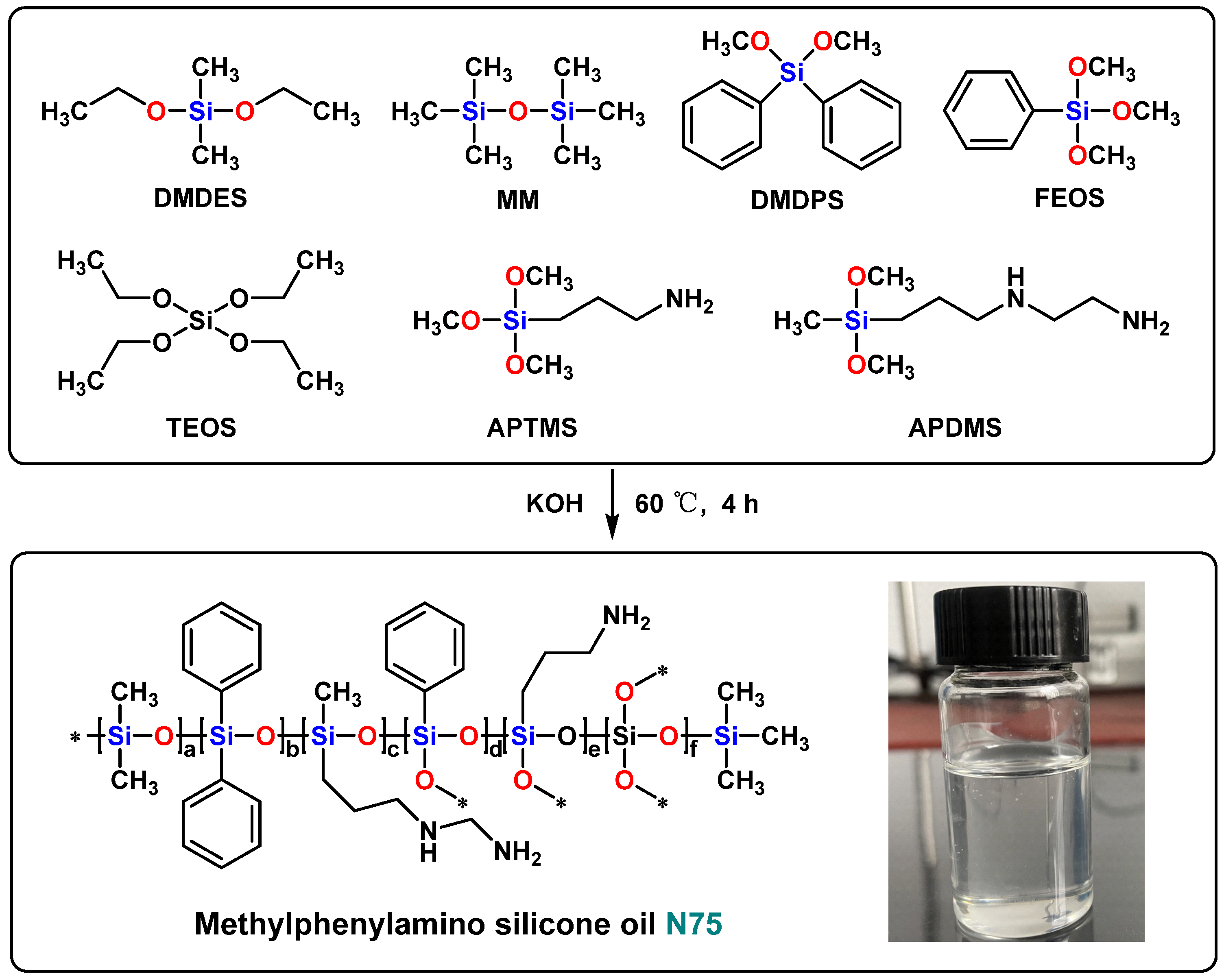
2.2. Synthesis of Methylphenylamino Silicone Oil (N75)
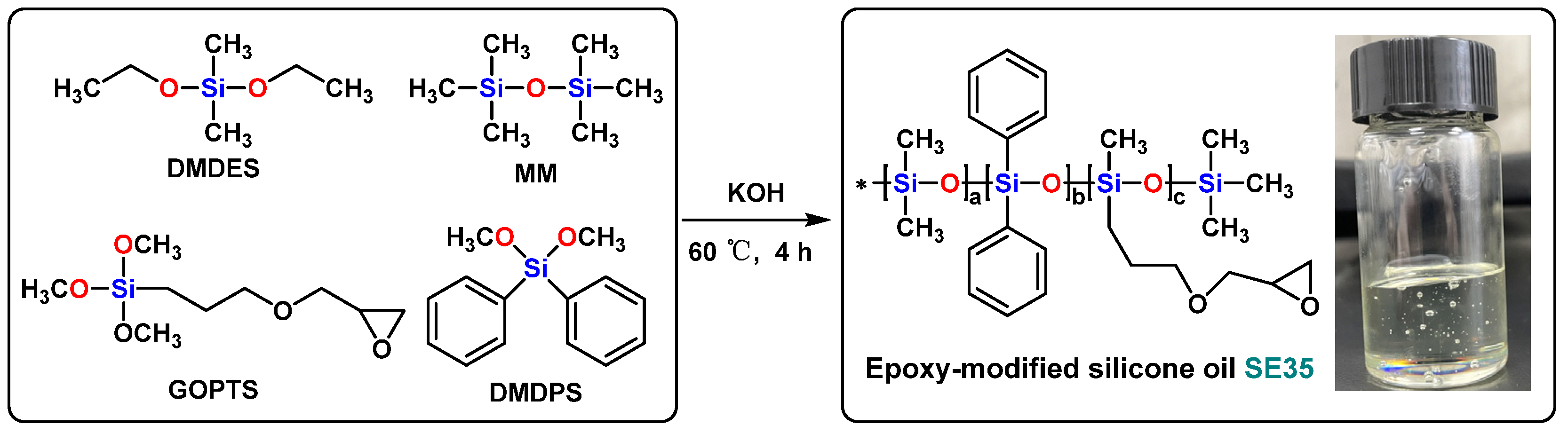
2.3. Synthesis of Epoxy-Modified Silicone Oil (SE35)
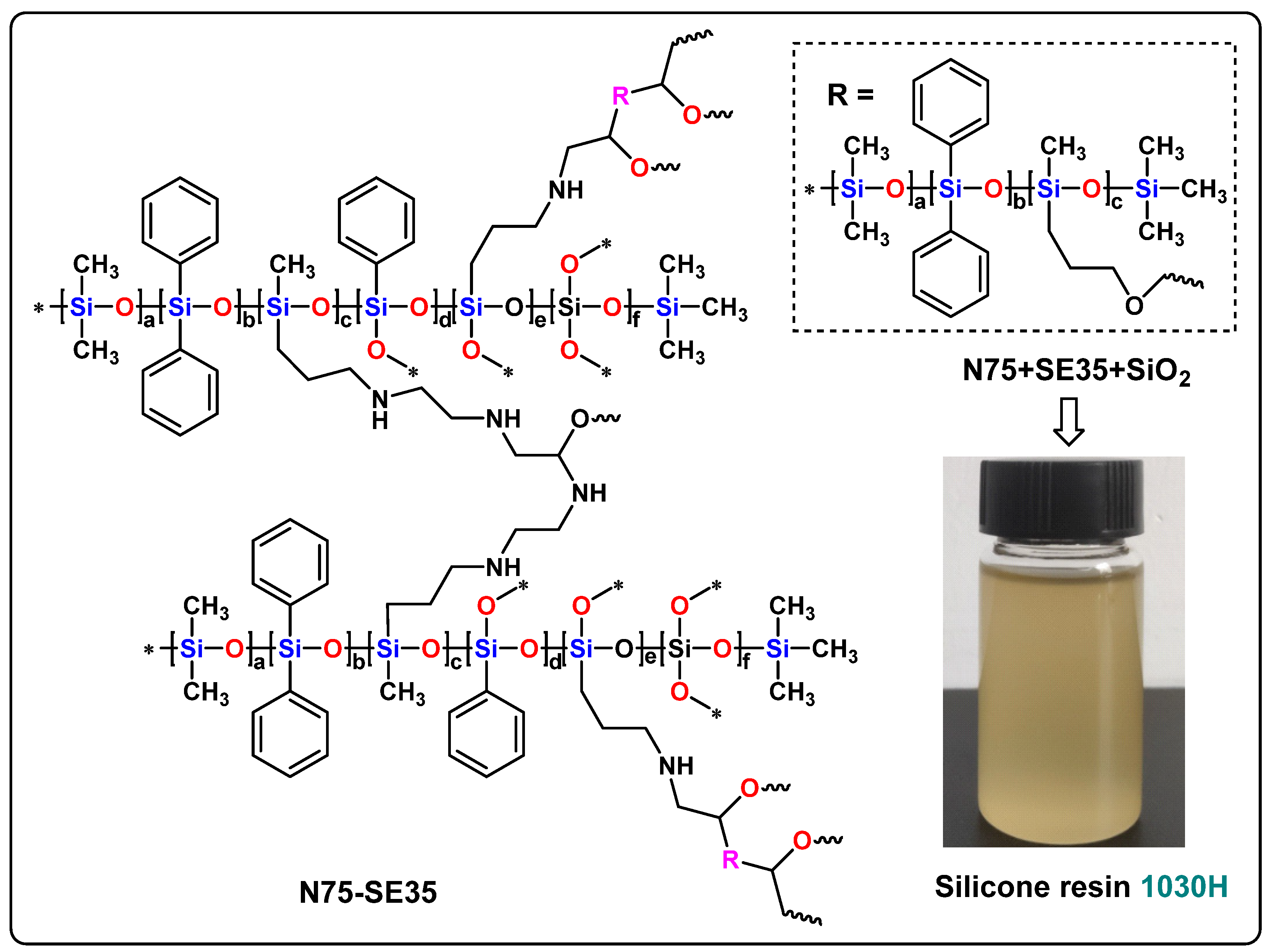
2.4. Preparation of 1030H Silicone Resin
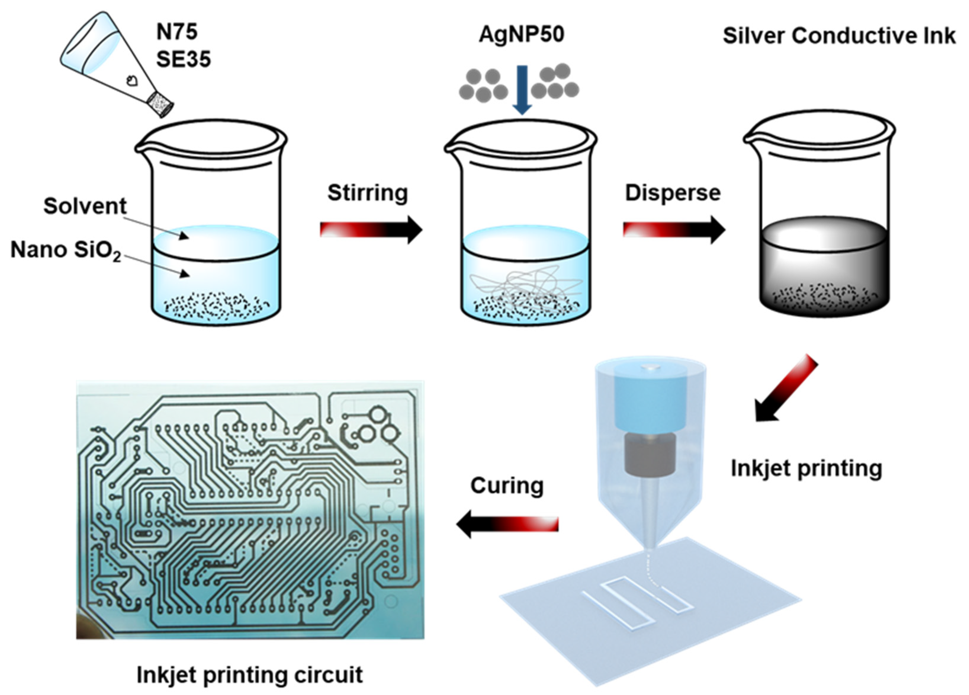
2.5. Preparation of Silver Conductive Ink
2.6. Characterization
3. Results and Discussion
3.1. Characterization of N75 and SE35
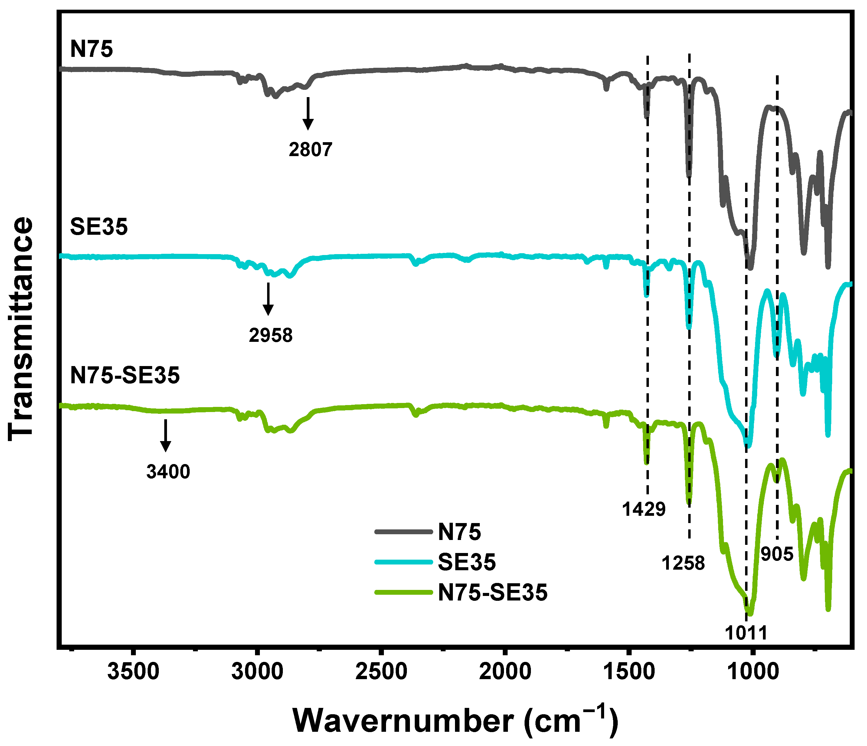
3.1.1. FT-IR
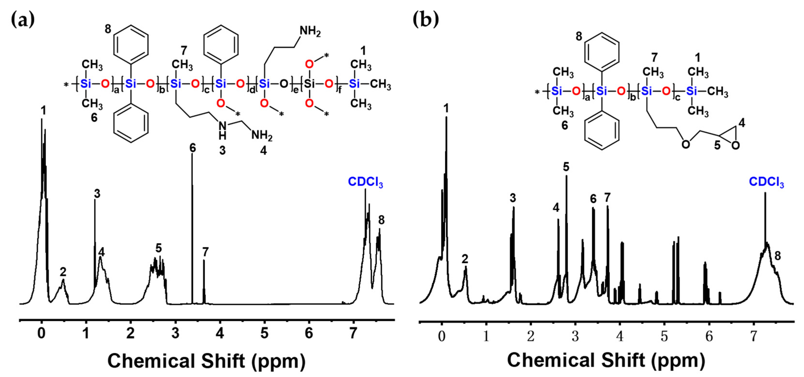
3.1.2. 1H-NMR
3.2. Properties of Silver Conductive Inks
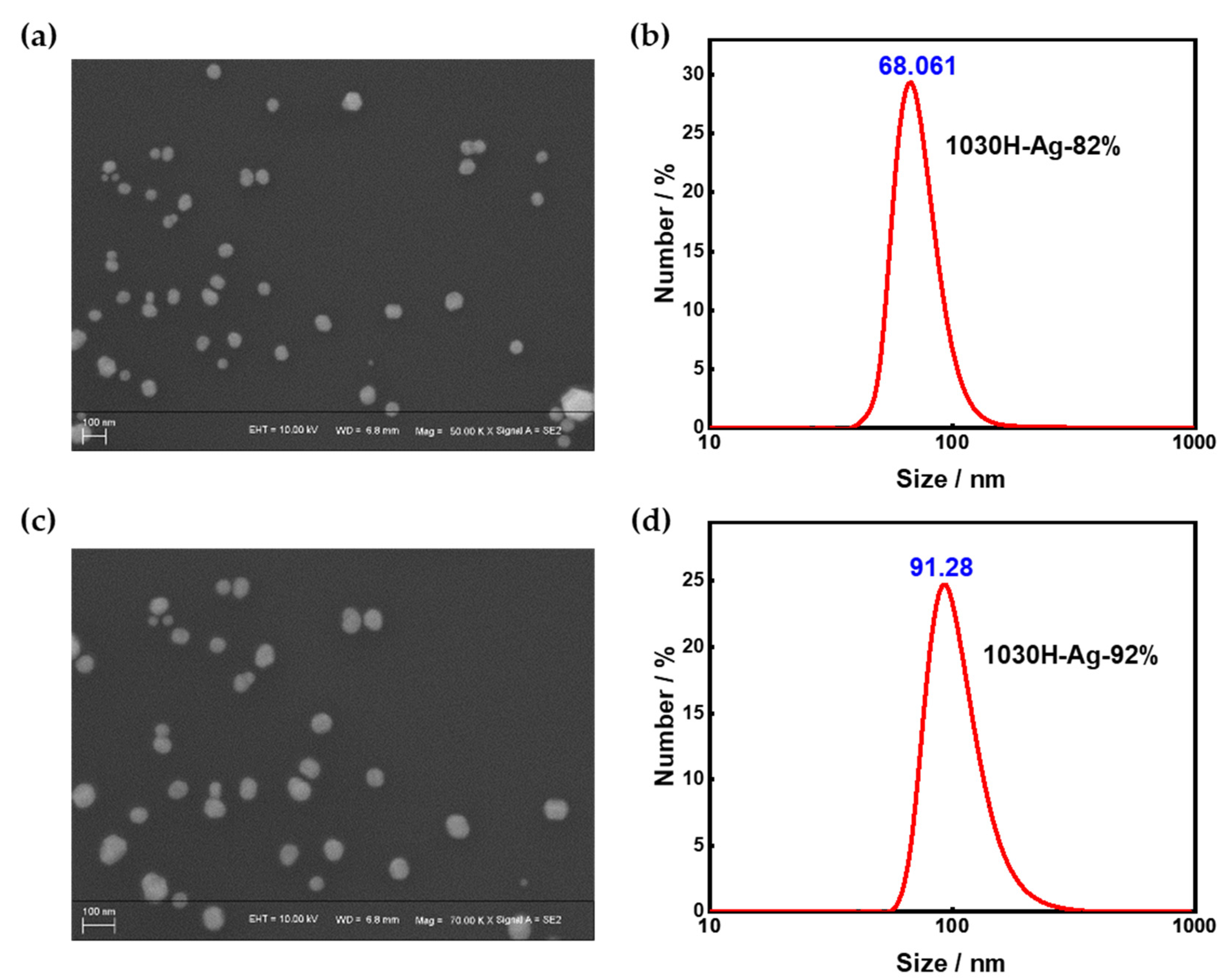
3.2.1. Particle Size
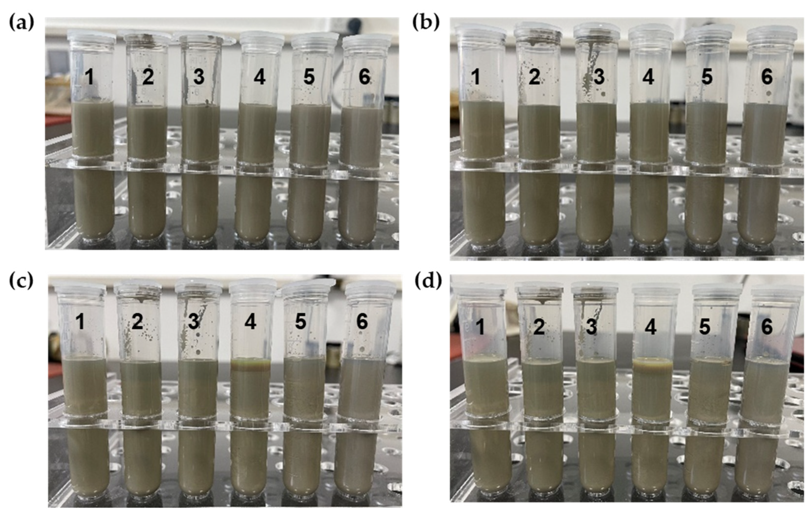
3.2.2. Storage Stability
3.2.3. Adhesion
3.2.4. Pencil Hardness
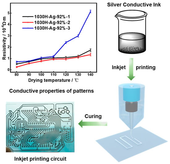
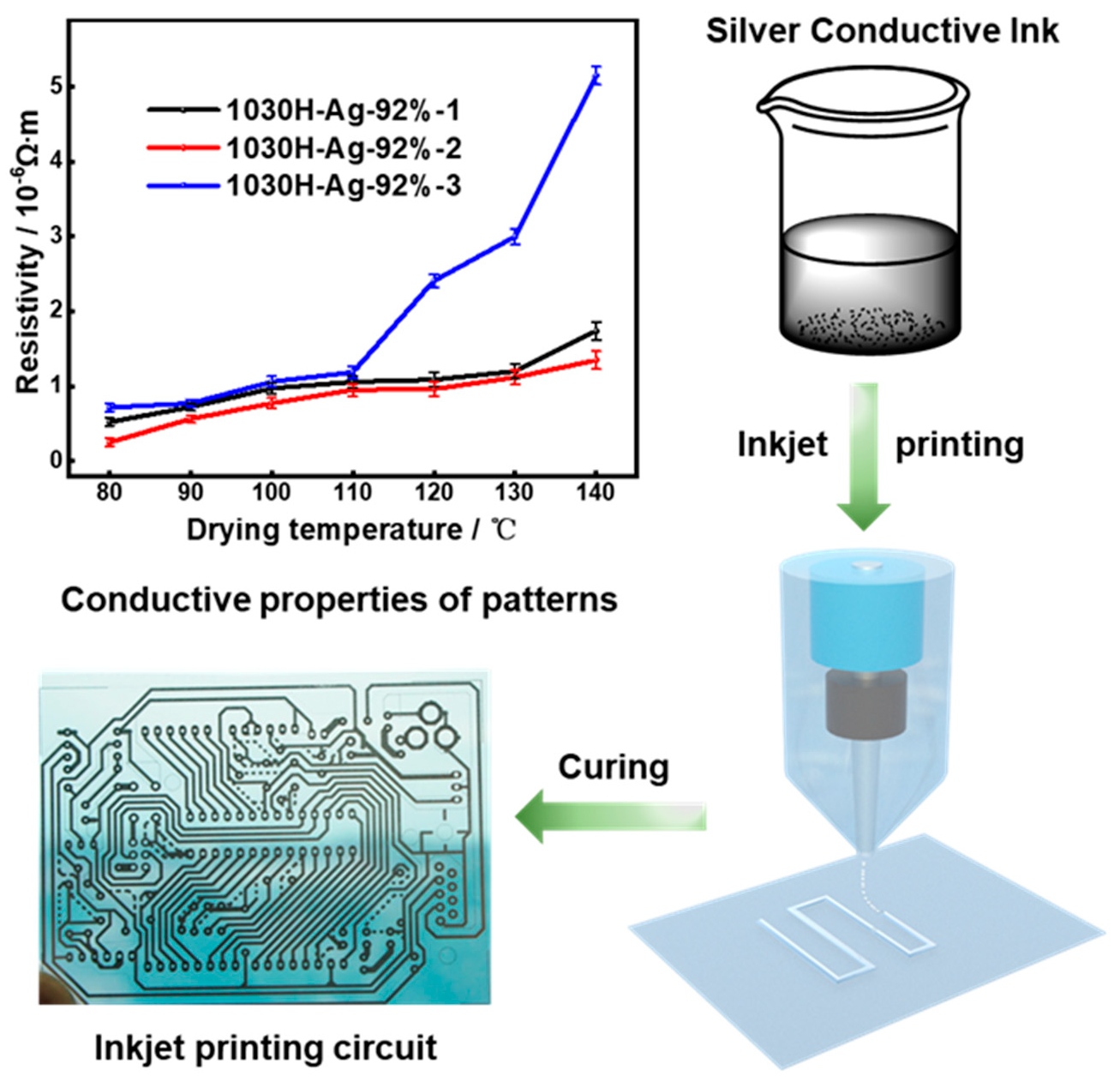
3.2.5. Conductivity
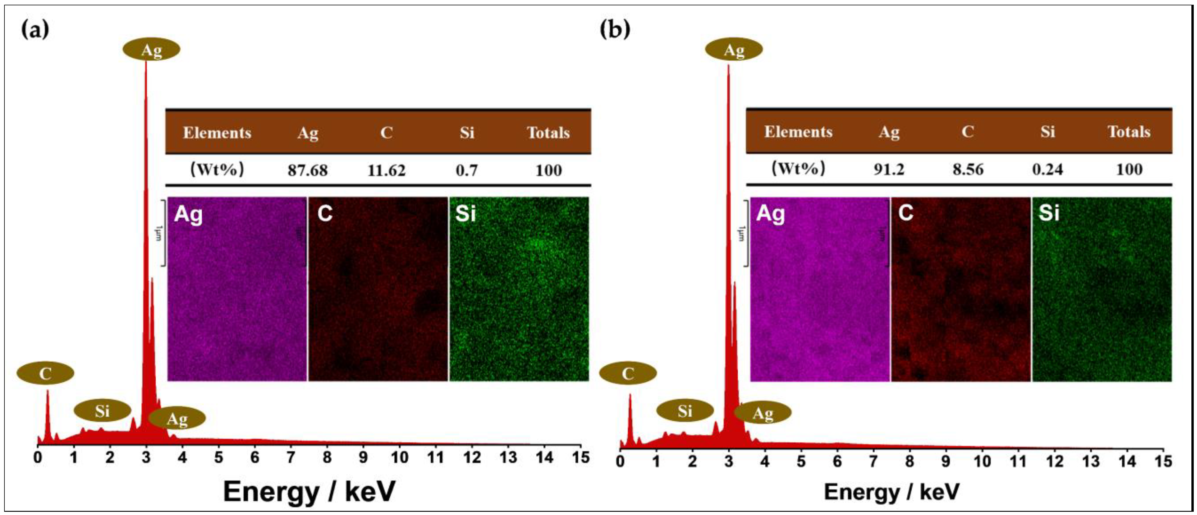
3.2.6. Elemental Composition
3.3. Effect of Solvent on Properties of Silver Conductive Ink
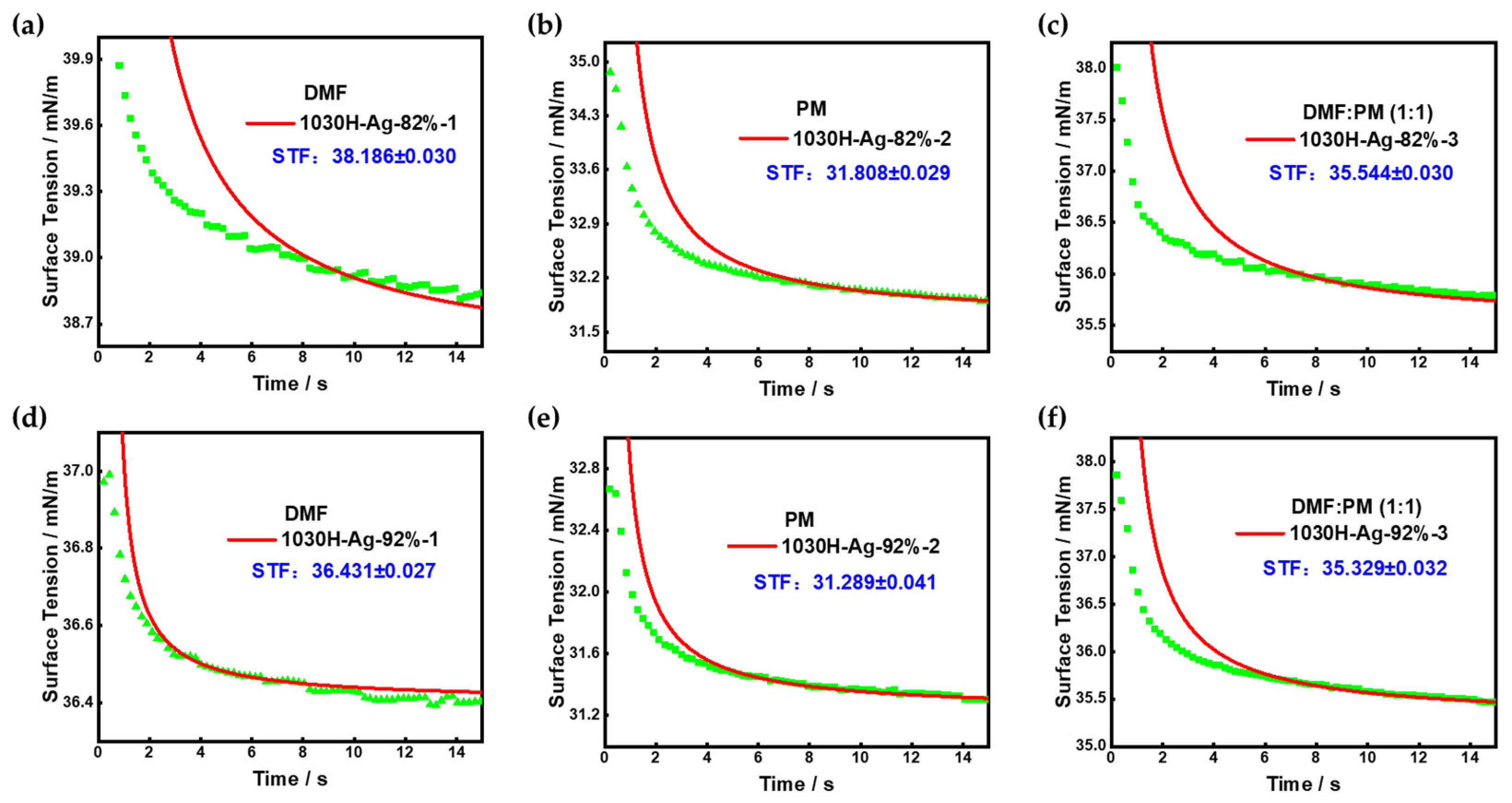
3.3.1. Surface Tension
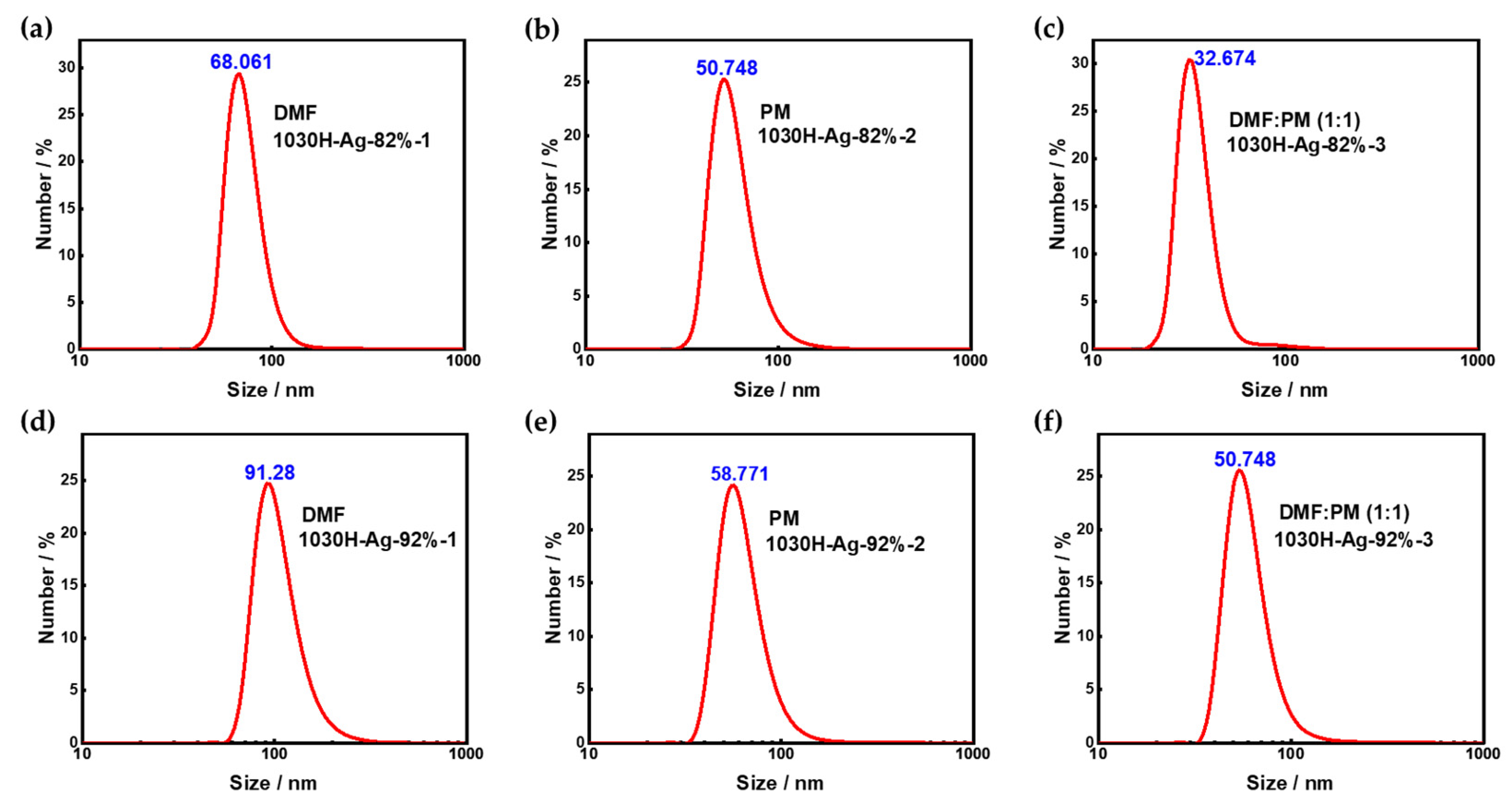
3.3.2. Particle Size
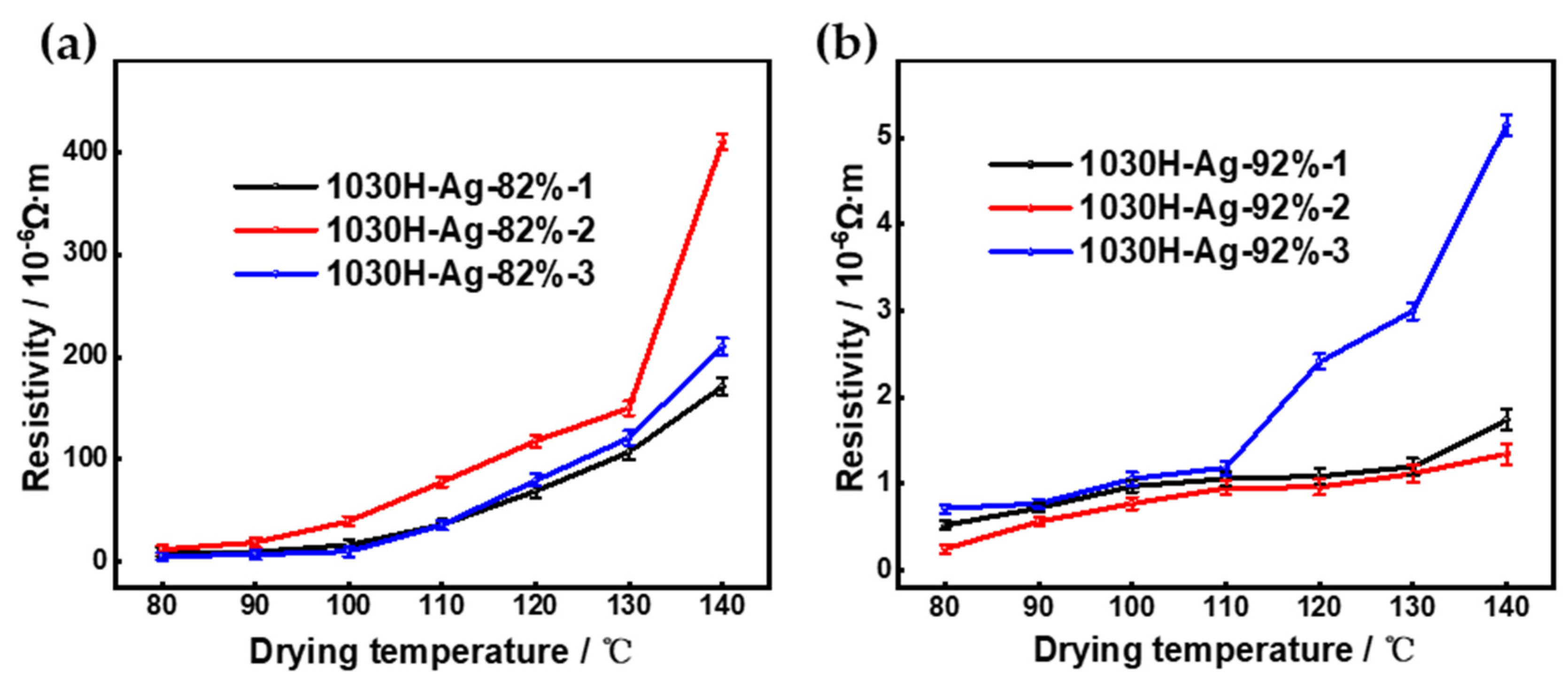
3.3.3. Conductivity
4. Conclusions
Author Contributions
Funding
Data Availability Statement
Acknowledgments
Conflicts of Interest
References
- Berggren, M.; Nilsson, D.; Robinson, N.D. Organic materials for printed electronics. Nat. Mater. 2007, 6, 3–5. [Google Scholar] [CrossRef]
- Perelaer, J.; Smith, P.J.; Mager, D.; Soltman, D.; Volkman, S.K.; Subramanian, V.; Korvink, J.G.; Schubert, U.S. Printed electronics: The challenges involved in printing devices, interconnects, and contacts based on inorganic materials. J. Mater. Chem. 2010, 20, 8446–8453. [Google Scholar] [CrossRef]
- Kamyshny, A.; Magdassi, S. Conductive nanomaterials for printed electronics. Small 2014, 10, 3515–3535. [Google Scholar] [CrossRef] [PubMed]
- Mohammed, M.G.; Kramer, R. All-printed flexible and stretchable electronics. Adv. Mater. 2017, 29, 1604965. [Google Scholar] [CrossRef] [PubMed]
- Zhan, Z.; An, J.; Wei, Y.; Du, H. Inkjet-printed optoelectronics. Nanoscale 2017, 9, 965–993. [Google Scholar] [CrossRef] [PubMed]
- Zhou, X.; Parida, K.; Halevi, O.; Liu, Y.; Xiong, J.; Magdassi, S.; Lee, P.S. All 3D-printed stretchable piezoelectric nanogenerator with non-protruding kirigami structure. Nano Energy 2020, 72, 104676. [Google Scholar] [CrossRef]
- Carbonell, C.; Valles, D.; Wong, A.M.; Carlini, A.S.; Touve, M.A.; Korpanty, J.; Gianneschi, N.C.; Braunschweig, A.B. Polymer brush hypersurface photolithography. Nat. Commun. 2020, 11, 1244. [Google Scholar] [CrossRef] [PubMed] [Green Version]
- Parashkov, R.; Becker, E.; Riedl, T.; Johannes, H.H.; Kowalsky, W. Large area electronics using printing methods. Proc. IEEE 2005, 93, 1321–1329. [Google Scholar] [CrossRef]
- Zhang, Y.; Zhang, T.; Shi, H.; Liu, Q.; Shi, Y.; Wang, T. Electroless plating cycle process for high-conductivity flexible printed circuits. ACS Sustainable Chem. Eng. 2021, 9, 11991–12004. [Google Scholar] [CrossRef]
- Kamyshny, A.; Magdassi, S. Conductive nanomaterials for 2D and 3D printed flexible electronics. Chem. Soc. Rev. 2019, 48, 1712–1740. [Google Scholar] [CrossRef]
- Huang, Q.; Zhu, Y. Printing conductive nanomaterials for flexible and stretchable electronics: A review of materials, processes, and applications. Adv. Mater. Technol. 2019, 4, 1800546. [Google Scholar] [CrossRef]
- Dankoco, M.D.; Tesfay, G.Y.; Benevent, E.; Bendahan, M. Temperature sensor realized by inkjet printing process on flexible substrate. J. Mater. Sci. Eng. B 2016, 205, 1–5. [Google Scholar] [CrossRef]
- Yin, X.-Y.; Zhang, Y.; Cai, X.; Guo, Q.; Yang, J.; Wang, Z.L. 3D printing of ionic conductors for high-sensitivity wearable sensors. Mater. Horiz. 2019, 6, 767–780. [Google Scholar] [CrossRef]
- Kwon, H.J.; Chung, S.; Jang, J.; Grigoropoulos, C.P. Laser direct writing and inkjet printing for a sub-2 μm channel length MoS2 transistor with high-resolution electrodes. Nanotechnology 2016, 27, 405301. [Google Scholar] [CrossRef]
- Chung, S.; Cho, K.; Lee, T. Recent progress in inkjet-printed thin-film transistors. Adv. Sci. 2019, 6, 1801445. [Google Scholar] [CrossRef] [PubMed]
- Peng, X.; Yuan, J.; Shen, S.; Gao, M.; Chesman, A.S.R.; Yin, H.; Cheng, J.; Zhang, Q.; Angmo, D. Perovskite and organic solar cells fabricated by inkjet printing: Progress and prospects. Adv. Funct. Mater. 2017, 27, 1703704. [Google Scholar] [CrossRef]
- Leow, S.W.; Li, W.; Tan, J.M.R.; Venkataraj, S.; Tunuguntla, V.; Zhang, M.; Magdassi, S.; Wong, L.H. Solution-processed semitransparent CZTS thin-film solar cells via cation substitution and rapid thermal annealing. Sol. RRL 2021, 5, 2100131. [Google Scholar] [CrossRef]
- Gao, Y.; Liu, R.; Wang, X.; Liu, J.; Fang, Q. Flexible RFID tag inductor printed by liquid metal ink printer and its characterization. J. Electron. Packag. 2016, 138, 031007. [Google Scholar] [CrossRef]
- Wittbrodt, B.; Pearce, J.M. 3-D printing solar photovoltaic racking in developing world. Energy Sustainable Dev. 2017, 36, 1–5. [Google Scholar] [CrossRef] [Green Version]
- Tolvanen, J.; Hannu, J.; Jantunen, H. Stretchable and washable strain sensor based on cracking structure for human motion monitoring. Sci. Rep. 2018, 8, 13241. [Google Scholar] [CrossRef]
- Khan, Y.; Thielens, A.; Muin, S.; Ting, J.; Baumbauer, C.; Arias, A.C. A new frontier of printed electronics: Flexible hybrid electronics. Adv. Mater. 2020, 32, 1905279. [Google Scholar] [CrossRef] [PubMed]
- Tang, C.; Zheng, S.; Wang, F.; Lu, Y.; Huang, F.; Xing, B.; Zuo, C. Microwave-assisted two-steps method for the facile preparation of silver nanoparticle conductive ink. J. Mater. Sci. 2019, 30, 11588–11597. [Google Scholar] [CrossRef]
- Senthil, K.; Chen, P.Y.; Ren, H. A review of printable flexible and stretchable tactile sensors. Research 2019, 2019, 3018568. [Google Scholar] [CrossRef] [Green Version]
- Camargo, J.R.; Orzari, L.O.; Araujo, D.A.G.; de Oliveira, P.R.; Kalinke, C.; Rocha, D.P.; Santos, A.L.; Takeuchi, R.M.; Munoz, R.A.A.; Bonacin, J.A. Development of conductive inks for electrochemical sensors and biosensors. Microchem. J. 2021, 164, 105998. [Google Scholar] [CrossRef]
- Zope, K.R.; Cormier, D.; Williams, S.A. Reactive silver oxalate ink composition with enhanced curing conditions for flexible substrates. ACS Appl. Mater. Interfaces 2018, 10, 3830–3837. [Google Scholar] [CrossRef]
- Li, J.; Zhang, X.; Liu, X.; Liang, Q.; Liao, G.; Tang, Z.; Shi, T. Conductivity and foldability enhancement of Ag patterns formed by PVAc modified Ag complex inks with low-temperature and rapid sintering. Mater. Des. 2020, 185, 108255. [Google Scholar] [CrossRef]
- Zhang, Y.; Cen, Q.; Xu, X.; Li, W.; Zhao, Y.; Li, W.; Liu, Q.; Chen, M.; Guo, N.; Wu, W.; et al. The effect of PVAc in silver ink for adhesion and conductivity of conductive pattern. J. Mater. Res. Technol. 2022, 18, 4277–4284. [Google Scholar] [CrossRef]
- Dai, X.; Xu, W.; Zhang, T.; Wang, T. Self-reducible Cu nanoparticles for conductive inks. Ind. Eng. Chem. Res. 2018, 57, 2508–2516. [Google Scholar] [CrossRef]
- Rosen, Y.; Marrach, R.; Gutkin, V.; Magdassi, S. Thin copper flakes for conductive inks prepared by decomposition of copper formate and ultrafine wet milling. Adv. Mater. Technol. 2019, 4, 1800426. [Google Scholar] [CrossRef]
- Wu, T.; Gray, E.; Chen, B. A self-healing, adaptive and conductive polymer composite ink for 3D printing of gas sensors. J. Mater. Chem. C 2018, 6, 6200–6207. [Google Scholar] [CrossRef] [Green Version]
- Yuk, H.; Lu, B.; Lin, S.; Qu, K.; Xu, J.; Luo, J.; Zhao, X. 3D printing of conducting polymers. Nat. Commun. 2020, 11, 1604. [Google Scholar] [CrossRef] [Green Version]
- Du, T.; Tang, C.; Xing, B.; Lu, Y.; Huang, F.; Zuo, C. Conductive ink prepared by microwave method: Effect of silver content on the pattern conductivity. J. Electron. Mater. 2019, 48, 231–237. [Google Scholar] [CrossRef]
- Cano, C.; Denchev, Z.Z.; Cruz, S.F.; Viana, J.C. Chemistry of solid metal-based inks and pastes for printed electronics–A review. Appl. Mater. Today 2019, 15, 416–430. [Google Scholar] [CrossRef]
- Hong, G.B.; Luo, Y.H.; Chuang, K.J.; Cheng, H.Y.; Chang, K.C.; Ma, C.M. Facile synthesis of silver nanoparticles and preparation of conductive ink. Nanomaterials 2022, 12, 171. [Google Scholar] [CrossRef] [PubMed]
- Zhang, J.; Ahmadi, M.; Fargas, G.; Perinka, N.; Reguera, J.; Lanceros, S.; Llanes, L.; Jiménez, E. Silver nanoparticles for conductive inks: From synthesis and ink formulation to their use in printing technologies. Metals 2022, 12, 234. [Google Scholar] [CrossRef]
- Wu, X.; Wang, S.; Luo, Z.; Lu, J.; Lin, K.; Xie, H.; Wang, Y.; Li, J.Z. Inkjet printing of flexible transparent conductive films with silver nanowires ink. Nanomaterials 2021, 11, 1571. [Google Scholar] [CrossRef] [PubMed]
- Pajor, A.; Szendera, F.; Pawłowski, R.; Szczepanowicz, K. Nanocomposite inks based on nickel-silver core–shell and silver nanoparticles for fabrication conductive coatings at low-temperature sintering. Colloids Interfaces 2021, 5, 15. [Google Scholar] [CrossRef]
- Shu, J.; Wang, Y.; Guo, B.; Qin, W.; Liu, L.; Liu, X. Effect of curing agents on electrical properties of low-temperature curing conductive coatings and thermodynamic analysis. Coatings 2021, 11, 656. [Google Scholar] [CrossRef]
- Zhou, L.; Chen, X.; Su, W.; Cui, Z.; Lai, W.Y. In-depth investigation of inkjet-printed silver electrodes over large-area: Ink recipe, flow, and solidification. Adv. Mater. Interfaces 2022, 9, 2102548. [Google Scholar] [CrossRef]
- Htwe, Y.Z.N.; Abdullah, M.K.; Mariatti, M. Water-based graphene/AgNPs hybrid conductive inks for flexible electronic applications. J. Mater. Res. Technol. 2022, 16, 59–73. [Google Scholar] [CrossRef]
- Ling, Y.Q.; Zhang, X.Q.; Yan, L.W.; Zhang, H.R.; Wang, Y.; Ge, Y.; Chen, Z.Y.; Chen, Y.; Zou, H.W.; Liang, M. Silicone-grafted epoxy/carbon fiber composites with superior mechanical/ablation performance. Mater. Chem. Phys. 2022, 275, 125283. [Google Scholar] [CrossRef]
- Würfel, H.; Kayser, M.; Heinze, T. Trimethylsilylation of polygalacturonic acid. Macromol. Chem. Phys. 2019, 220, 1900002. [Google Scholar] [CrossRef]
- Yan, D.; Liu, L.; Song, R. Direct growth of CNTs on in situ formed siliceous micro-flakes just by one-step pyrolyzation of polypropylene blends. J. Mater. Sci. 2015, 50, 1309–1316. [Google Scholar] [CrossRef]
- Rahman, M.M.; Chun, H.-H.; Park, H. Waterborne polysiloxane-urethane-urea for potential marine coatings. J. Coat. Technol. Res. 2011, 8, 389–399. [Google Scholar] [CrossRef]
- Otts, D.B.; Heidenreich, E.; Urban, M.W. Novel waterborne UV-crosslinkable thiol-ene polyurethane dispersions: Synthesis and film formation. Polymer 2005, 46, 8162–8168. [Google Scholar] [CrossRef]
- Vasil, S.G.; Volkov, V.I.; Tatarinova, E.A.; Muzafarov, A.M. Study of self-diffusion of silicone MQ resins in chloroform solutions by pulsed field-gradient NMR spectroscopy. Appl. Magn. Reson. 2014, 45, 315–328. [Google Scholar] [CrossRef]
- Chen, J.; Li, Y.; Lai, X.; Li, H.; Zeng, X. Synthesis and characterization of ureido-containing MQ silicone resin. J. Macromol. Sci. Part A 2019, 56, 1141–1147. [Google Scholar] [CrossRef]
- Zhu, T.; Cheng, Y.; Huang, J.; Xiong, J.; Ge, M.; Mao, J.; Liu, Z.; Dong, X.; Chen, Z.; Lai, Y. A transparent superhydrophobic coating with mechanochemical robustness for anti-icing, photocatalysis and self-cleaning. Chem. Eng. J. 2020, 399, 125746. [Google Scholar] [CrossRef]
- Shirai, M.; Okamura, H. UV-curable positive photoresists for screen printing plate. Polym. Int. 2016, 65, 362–370. [Google Scholar] [CrossRef]


| Conductive Ink | Nano Silver (wt%) | 1030H Silicone Resin (wt%) | DMF (wt%) | Adhesion Result | Pencil Hardness | Resistivity (×10−6 Ω·m) |
|---|---|---|---|---|---|---|
| 1030H-Ag-78% | 45.05 | 12.71 | 42.25 | 5B | 3H | 934 |
| 1030H-Ag-80% | 46.36 | 11.59 | 42.05 | 5B | 3H | 591 |
| 1030H-Ag-81% | 47.02 | 11.03 | 41.95 | 5B | 3H | 104 |
| 1030H-Ag-82% | 47.68 | 10.47 | 41.85 | 5B | 3H | 28.10 |
| 1030H-Ag-84% | 48.11 | 9.16 | 42.73 | 5B | 2H | 21.50 |
| 1030H-Ag-86% | 50.35 | 8.20 | 41.45 | 5B | 2H | 9.42 |
| 1030H-Ag-88% | 50.98 | 6.95 | 42.07 | 5B | 2H | 4.82 |
| 1030H-Ag-90% | 52.44 | 5.83 | 41.74 | 4B | 2H | 1.73 |
| 1030H-Ag-92% | 53.92 | 4.69 | 41.40 | 4B | 2H | 1.43 |
| Conductive Ink | Nano Silver (wt%) | 1030H Silicone Resin (wt%) | Solvent (wt%) | Solvent |
|---|---|---|---|---|
| 1030H-Ag-82%-1 | 47.68 | 10.47 | 41.85 | DMF |
| 1030H-Ag-82%-2 | 47.68 | 10.47 | 41.85 | PM |
| 1030H-Ag-82%-3 | 47.68 | 10.47 | 41.85 | DMF:PM (1:1) |
| 1030H-Ag-92%-1 | 53.92 | 4.69 | 41.40 | DMF |
| 1030H-Ag-92%-2 | 53.92 | 4.69 | 41.40 | PM |
| 1030H-Ag-92%-3 | 53.92 | 4.69 | 41.40 | DMF:PM (1:1) |
Disclaimer/Publisher’s Note: The statements, opinions and data contained in all publications are solely those of the individual author(s) and contributor(s) and not of MDPI and/or the editor(s). MDPI and/or the editor(s) disclaim responsibility for any injury to people or property resulting from any ideas, methods, instructions or products referred to in the content. |
© 2023 by the authors. Licensee MDPI, Basel, Switzerland. This article is an open access article distributed under the terms and conditions of the Creative Commons Attribution (CC BY) license (https://creativecommons.org/licenses/by/4.0/).
Share and Cite
Tang, Z.; Liu, Y.; Zhang, Y.; Sun, Z.; Huang, W.; Chen, Z.; Jiang, X.; Zhao, L. Design and Synthesis of Functional Silane-Based Silicone Resin and Application in Low-Temperature Curing Silver Conductive Inks. Nanomaterials 2023, 13, 1137. https://doi.org/10.3390/nano13061137
Tang Z, Liu Y, Zhang Y, Sun Z, Huang W, Chen Z, Jiang X, Zhao L. Design and Synthesis of Functional Silane-Based Silicone Resin and Application in Low-Temperature Curing Silver Conductive Inks. Nanomaterials. 2023; 13(6):1137. https://doi.org/10.3390/nano13061137
Chicago/Turabian StyleTang, Zhiqiang, Yanxia Liu, Yagang Zhang, Zicai Sun, Weidong Huang, Zhikai Chen, Xiaoli Jiang, and Lin Zhao. 2023. "Design and Synthesis of Functional Silane-Based Silicone Resin and Application in Low-Temperature Curing Silver Conductive Inks" Nanomaterials 13, no. 6: 1137. https://doi.org/10.3390/nano13061137