
Investigations on Grating-Enhanced Waveguides for Wide-Angle Light Couplings

Abstract
:1. Introduction
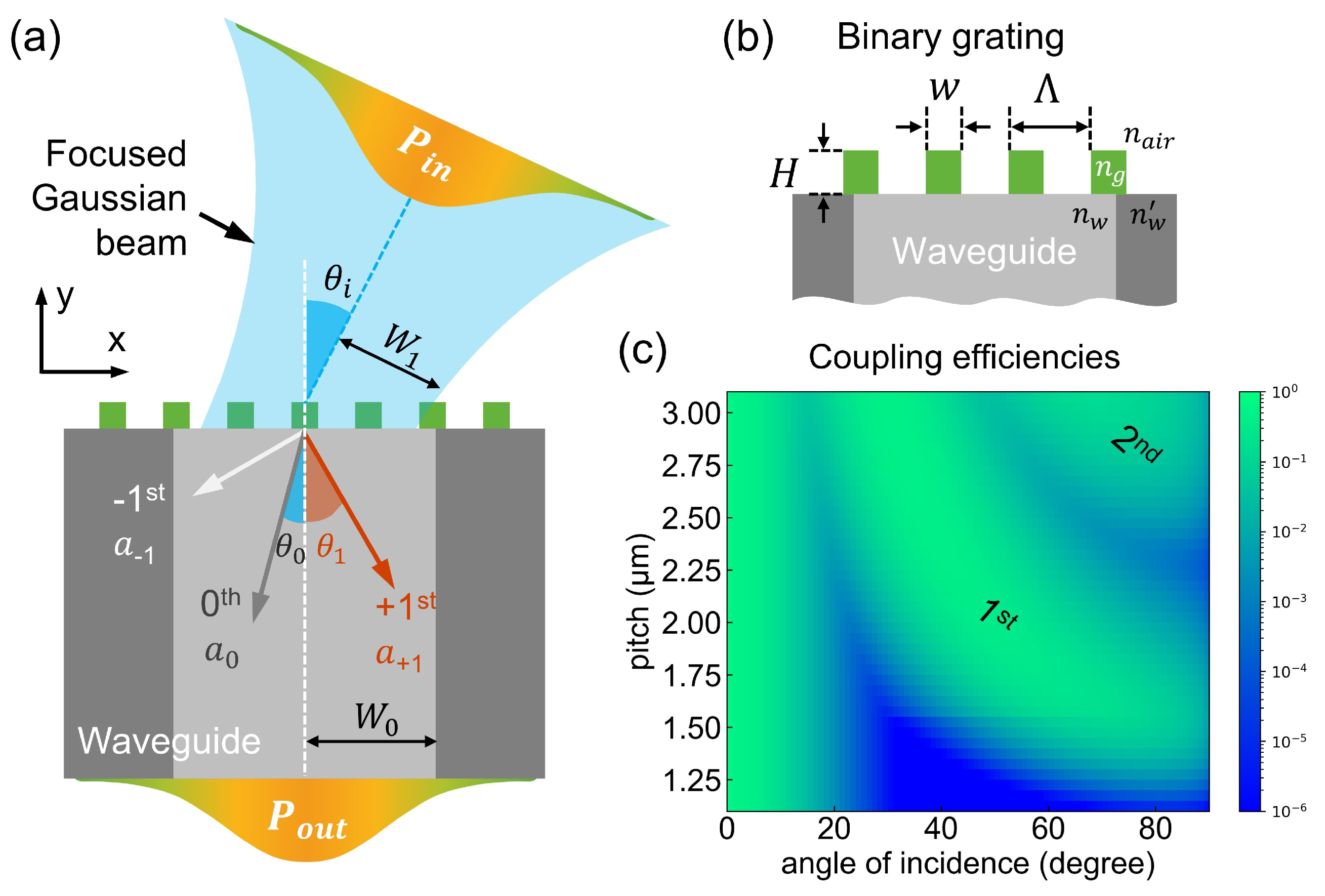
2. Concept of Grating-Assisted Waveguide Couplings
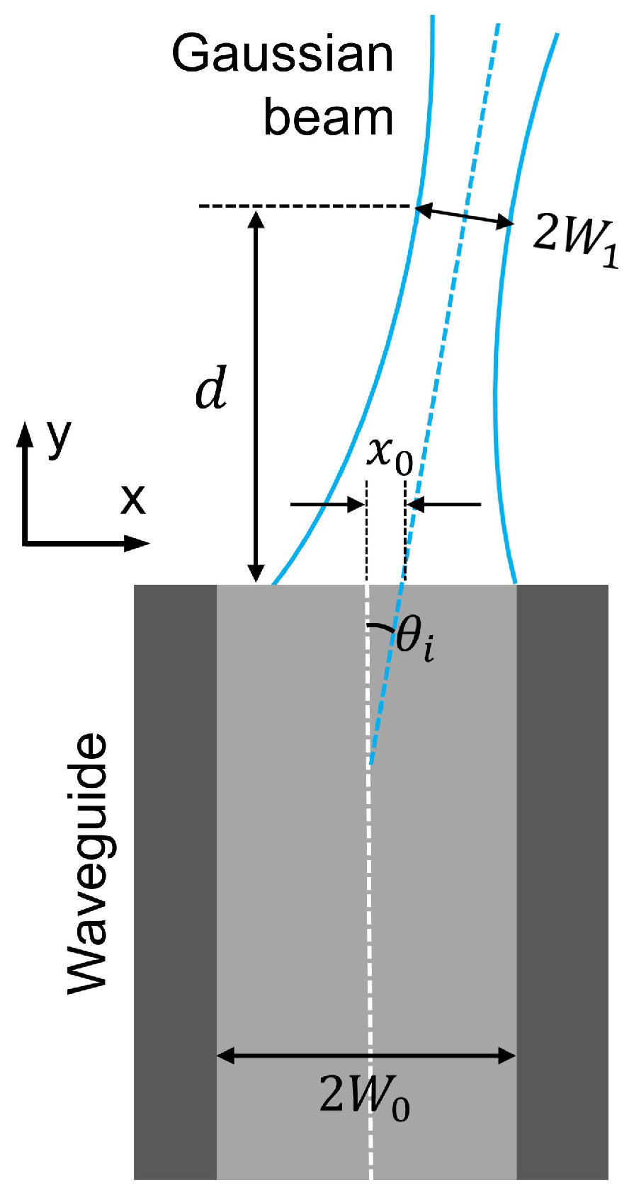
3. Theoretical Model
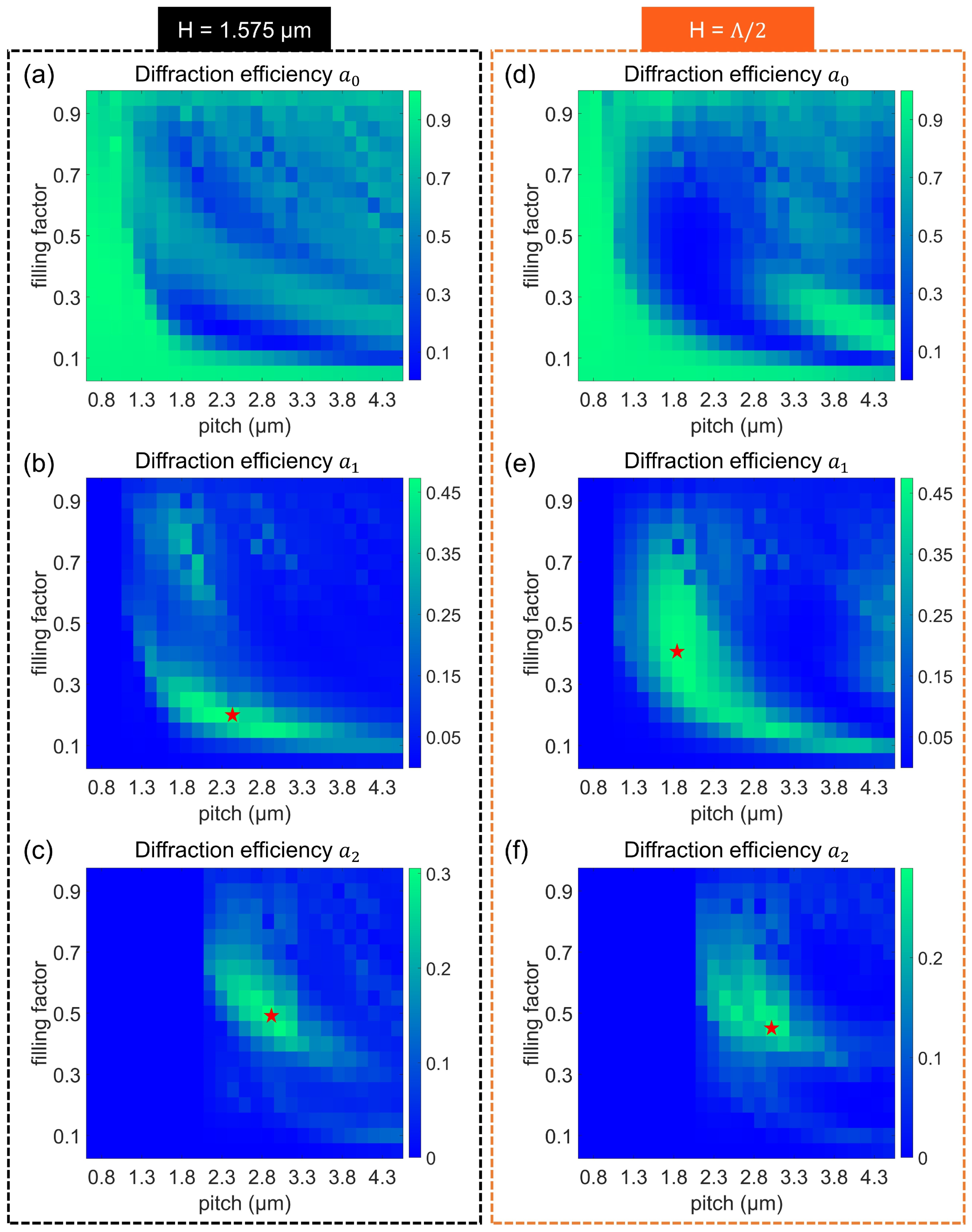
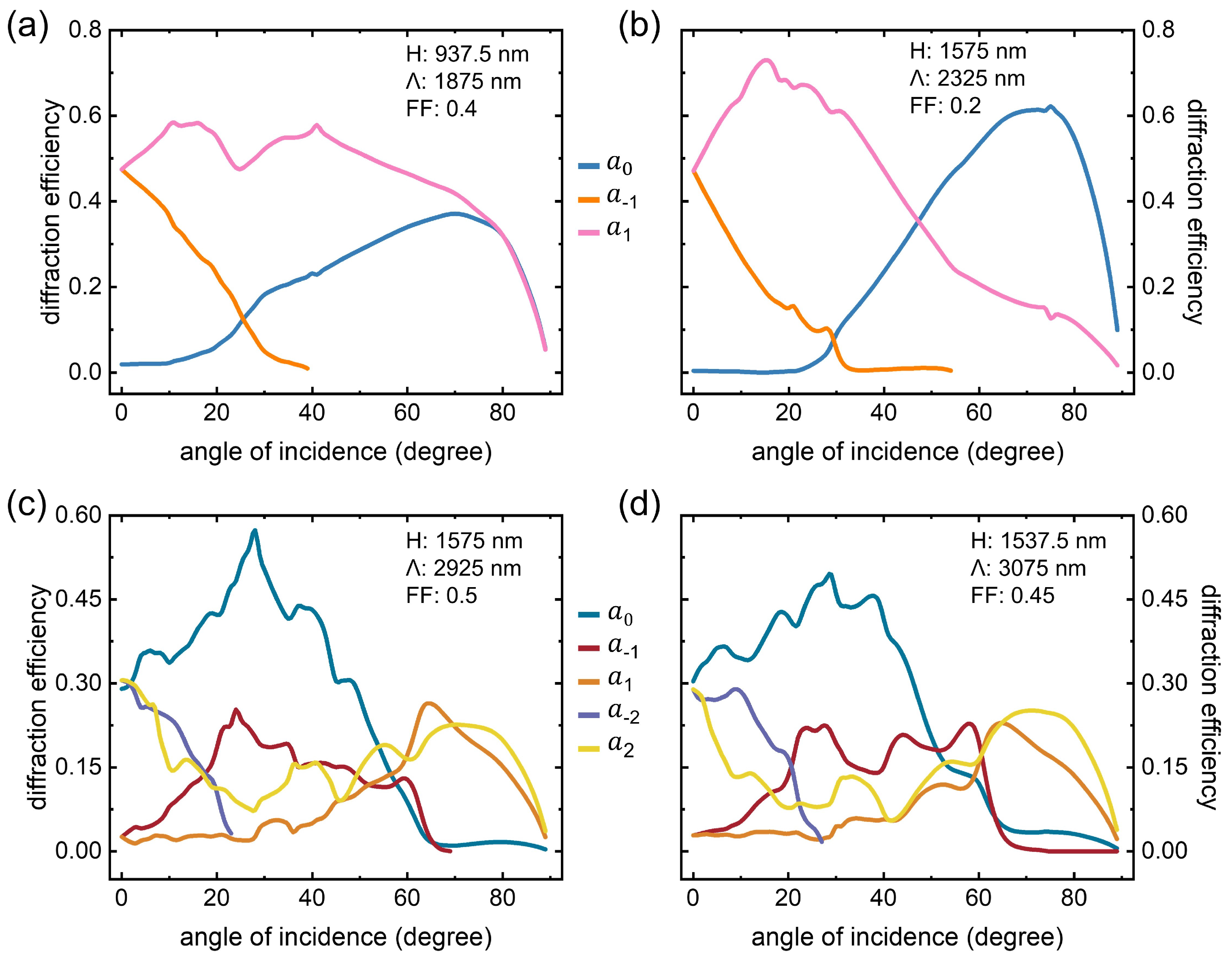
4. Binary Coupling Grating
5. Gratings under Large Inputs
6. Coupling Efficiency of Grating-Based Waveguides
7. Conclusions
Supplementary Materials
Author Contributions
Funding
Institutional Review Board Statement
Informed Consent Statement
Data Availability Statement
Conflicts of Interest
References
- Snyder, A.W.; Love, J. Optical Waveguide Theory; Springer Science & Business Media: Berlin/Heidelberg, Germany, 2012. [Google Scholar]
- Birks, T.A.; Knight, J.C.; Russell, P.S.J. Endlessly single-mode photonic crystal fiber. Opt. Lett. 1997, 22, 961–963. [Google Scholar] [CrossRef] [PubMed]
- Kumar, P.; Chen, J.; Voss, P.L.; Li, X.; Lee, K.F.; Sharping, J.E. Fiber-optic quantum information technologies. In Optical Fiber Telecommunications VA, 5th ed.; Elsevier: Amsterdam, The Netherlands, 2008; pp. 829–880. [Google Scholar]
- Wang, N.; Zeisberger, M.; Hübner, U.; Schmidt, M.A. Nanotrimer enhanced optical fiber tips implemented by electron beam lithography. Opt. Mater. Express 2018, 8, 2246–2255. [Google Scholar] [CrossRef]
- Schmidt, M.A.; Argyros, A.; Sorin, F. Hybrid optical fibers—An innovative platform for in-fiber photonic devices. Adv. Opt. Mater. 2015, 4, 13–36. [Google Scholar] [CrossRef]
- Liu, N.; Mukherjee, S.; Bao, K.; Li, Y.; Brown, L.V.; Nordlander, P.; Halas, N.J. Manipulating magnetic plasmon propagation in metallic nanocluster networks. ACS Nano 2012, 6, 5482–5488. [Google Scholar] [CrossRef]
- Gerislioglu, B.; Ahmadivand, A.; Pala, N. Single-and multimode beam propagation through an optothermally controllable Fano clusters-mediated waveguide. J. Light. Technol. 2017, 35, 4961–4966. [Google Scholar] [CrossRef]
- Meng, Y.; Chen, Y.; Lu, L.; Ding, Y.; Cusano, A.; Fan, J.A.; Hu, Q.; Wang, K.; Xie, Z.; Liu, Z.; et al. Optical meta-waveguides for integrated photonics and beyond. Light Sci. Appl. 2021, 10, 1–44. [Google Scholar] [CrossRef]
- Saleh, B.E.; Teich, M.C.; Saleh, B.E. Fundamentals of Photonics; Wiley: New York, NY, USA, 1991; Volume 22. [Google Scholar]
- Winzer, P.J.; Leeb, W.R. Fiber coupling efficiency for random light and its applications to lidar. Opt. Lett. 1998, 23, 986–988. [Google Scholar] [CrossRef]
- Edwards, C.A.; Presby, H.M.; Dragone, C. Ideal microlenses for laser to fiber coupling. J. Light. Technol. 1993, 11, 252–257. [Google Scholar] [CrossRef]
- Cordero, E.; Latka, I.; Matthäus, C.; Schie, I.W.; Popp, J. In-vivo Raman spectroscopy: From basics to applications. J. Biomed. Opt. 2018, 23, 071210. [Google Scholar] [CrossRef]
- Kennedy, K.M.; Kennedy, B.F.; McLaughlin, R.A.; Sampson, D.D. Needle optical coherence elastography for tissue boundary detection. Opt. Lett. 2012, 37, 2310–2312. [Google Scholar] [CrossRef]
- Pahlevaninezhad, H.; Khorasaninejad, M.; Huang, Y.W.; Shi, Z.; Hariri, L.P.; Adams, D.C.; Ding, V.; Zhu, A.; Qiu, C.W.; Capasso, F.; et al. Nano-optic endoscope for high-resolution optical coherence tomography in vivo. Nat. Photonics 2018, 12, 540–547. [Google Scholar] [CrossRef] [PubMed]
- Li, X.; Scully, R.A.; Shayan, K.; Luo, Y.; Strauf, S. Near-unity light collection efficiency from quantum emitters in boron nitride by coupling to metallo-dielectric antennas. ACS Nano 2019, 13, 6992–6997. [Google Scholar] [CrossRef] [PubMed]
- Wang, N.; Zeisberger, M.; Hübner, U.; Schmidt, M.A. Boosting light collection efficiency of optical fibers using metallic nanostructures. ACS Photonics 2019, 6, 691–698. [Google Scholar] [CrossRef]
- Yuan, S.; Riza, N.A. General formula for coupling-loss characterization of single-mode fiber collimators by use of gradient-index rod lenses. Appl. Opt. 1999, 38, 3214–3222. [Google Scholar] [CrossRef]
- Gomez-Reino, C.; Perez, M.V.; Bao, C.; Flores-Arias, M.T. Design of GRIN optical components for coupling and interconnects. Laser Photonics Rev. 2008, 2, 203–215. [Google Scholar] [CrossRef]
- Yermakov, O.; Schneidewind, H.; Hübner, U.; Wieduwilt, T.; Zeisberger, M.; Bogdanov, A.; Kivshar, Y.; Schmidt, M.A. Nanostructure-empowered efficient coupling of light into optical fibers at extraordinarily large angles. ACS Photonics 2020, 7, 2834–2841. [Google Scholar] [CrossRef]
- Wang, N.; Zeisberger, M.; Hübner, U.; Schmidt, M.A. Nanograting-Enhanced Optical Fibers for Visible and Infrared Light Collection at Large Input Angles. Photonics 2021, 8, 295. [Google Scholar] [CrossRef]
- Decker, M.; Staude, I.; Falkner, M.; Dominguez, J.; Neshev, D.N.; Brener, I.; Pertsch, T.; Kivshar, Y.S. High-efficiency dielectric Huygens’ surfaces. Adv. Opt. Mater. 2015, 3, 813–820. [Google Scholar] [CrossRef] [Green Version]
- Palmer, C.; Loewen, E.G. Diffraction Grating Handbook; Newport Corporation: New York, NY, USA, 2005. [Google Scholar]
- Loewen, E.G.; Popov, E. Diffraction Gratings and Applications; CRC Press: Boca Raton, FL, USA, 2018. [Google Scholar]
- Bonod, N.; Neauport, J. Diffraction gratings: From principles to applications in high-intensity lasers. Adv. Opt. Photonics 2016, 8, 156–199. [Google Scholar] [CrossRef] [Green Version]
- Saruwatari, M.; Nawata, K. Semiconductor laser to single-mode fiber coupler. Appl. Opt. 1979, 18, 1847–1856. [Google Scholar] [CrossRef]
- Niu, J.; Xu, J. Coupling efficiency of laser beam to multimode fiber. Opt. Commun. 2007, 274, 315–319. [Google Scholar] [CrossRef]
- Paniagua-Dominguez, R.; Yu, Y.F.; Khaidarov, E.; Choi, S.; Leong, V.; Bakker, R.M.; Liang, X.; Fu, Y.H.; Valuckas, V.; Krivitsky, L.A.; et al. A metalens with a near-unity numerical aperture. Nano Lett. 2018, 18, 2124–2132. [Google Scholar] [CrossRef] [PubMed] [Green Version]
- Kanwal, S.; Wen, J.; Yu, B.; Kumar, D.; Chen, X.; Kang, Y.; Bai, C.; Zhang, D. High-efficiency, broadband, near diffraction-limited, dielectric metalens in ultraviolet spectrum. Nanomaterials 2020, 10, 490. [Google Scholar] [CrossRef] [PubMed] [Green Version]
- Plidschun, M.; Ren, H.; Kim, J.; Förster, R.; Maier, S.A.; Schmidt, M.A. Ultrahigh numerical aperture meta-fibre for flexible optical trapping. Light Sci. Appl. 2021, 10, 1–11. [Google Scholar] [CrossRef]
- Wang, N.; Yan, W.; Qu, Y.; Ma, S.; Li, S.Z.; Qiu, M. Intelligent designs in nanophotonics: From optimization towards inverse creation. PhotoniX 2021, 2, 1–35. [Google Scholar] [CrossRef]


| Structure (Gaussian Beam Excitation) | Max | |
|---|---|---|
| Analytical Model | FEM | |
| Seven-ring ( = 1575 nm) | N.A. | 0.16 (70) |
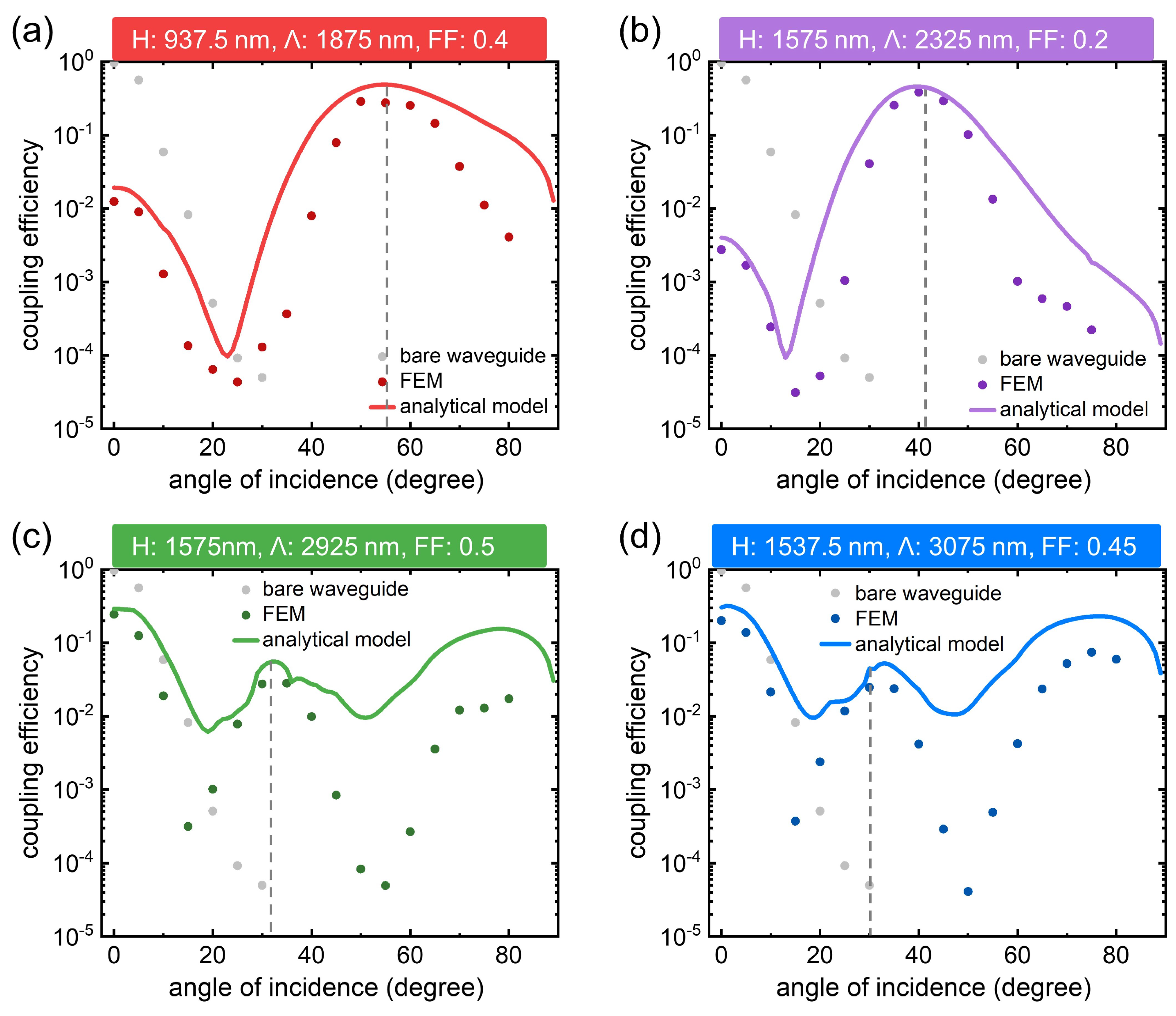
| Grating ( = 1875 nm) | 0.485 (55) | 0.286 (50) |
| Grating ( = 2325 nm) | 0.459 (40) | 0.384 (40) |
| Grating ( = 2925 nm) | 0.055 (32), 0.15 (77) | 0.028(35), 0.017 (80) |
| Grating ( = 3075 nm) | 0.053 (33), 0.23 (77) | 0.025 (30), 0.074 (75) |
Publisher’s Note: MDPI stays neutral with regard to jurisdictional claims in published maps and institutional affiliations. |
© 2022 by the authors. Licensee MDPI, Basel, Switzerland. This article is an open access article distributed under the terms and conditions of the Creative Commons Attribution (CC BY) license (https://creativecommons.org/licenses/by/4.0/).
Share and Cite
Gu, Y.; Wang, N.; Shang, H.; Yu, F.; Hu, L. Investigations on Grating-Enhanced Waveguides for Wide-Angle Light Couplings. Nanomaterials 2022, 12, 3991. https://doi.org/10.3390/nano12223991
Gu Y, Wang N, Shang H, Yu F, Hu L. Investigations on Grating-Enhanced Waveguides for Wide-Angle Light Couplings. Nanomaterials. 2022; 12(22):3991. https://doi.org/10.3390/nano12223991
Chicago/Turabian StyleGu, Yitong, Ning Wang, Haorui Shang, Fei Yu, and Lili Hu. 2022. "Investigations on Grating-Enhanced Waveguides for Wide-Angle Light Couplings" Nanomaterials 12, no. 22: 3991. https://doi.org/10.3390/nano12223991