
Compositionally-Driven Formation Mechanism of Hierarchical Morphologies in Co-Deposited Immiscible Alloy Thin Films

 , , and
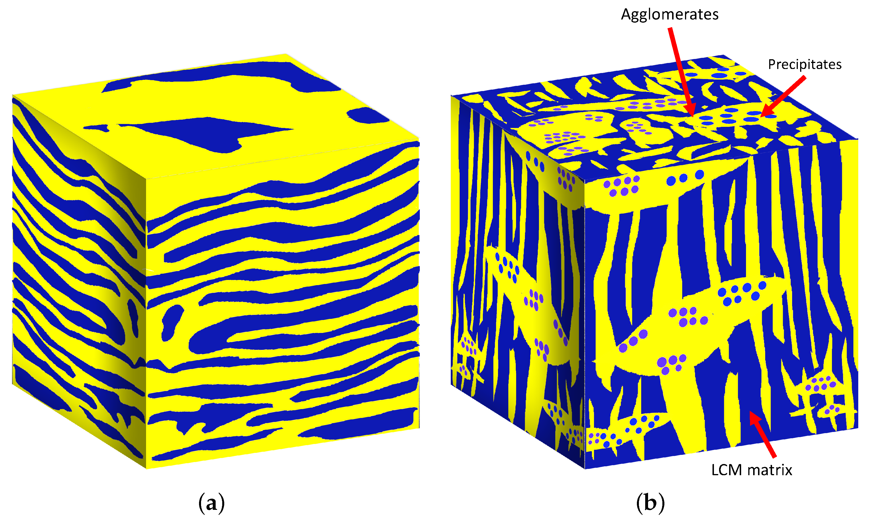
Abstract
:1. Introduction
2. Methods
2.1. Phase-Field Model
2.2. Synthesis and Characterization of Co-Sputtered Cu-Mo Thin Films
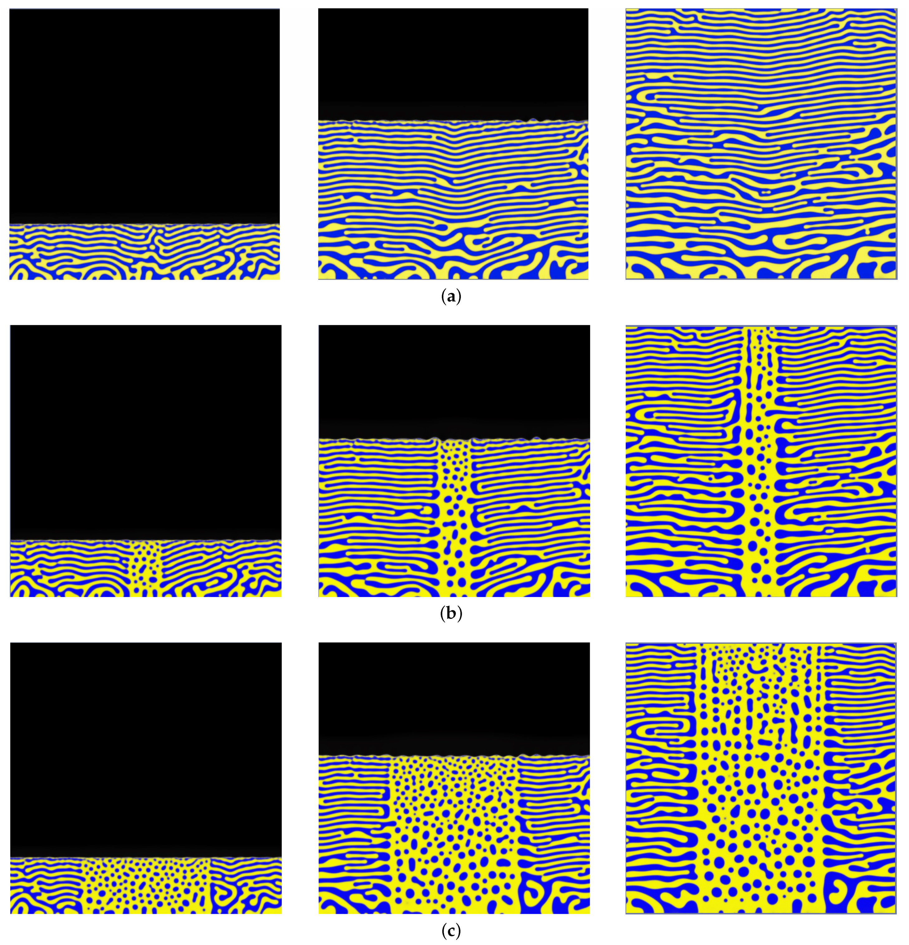
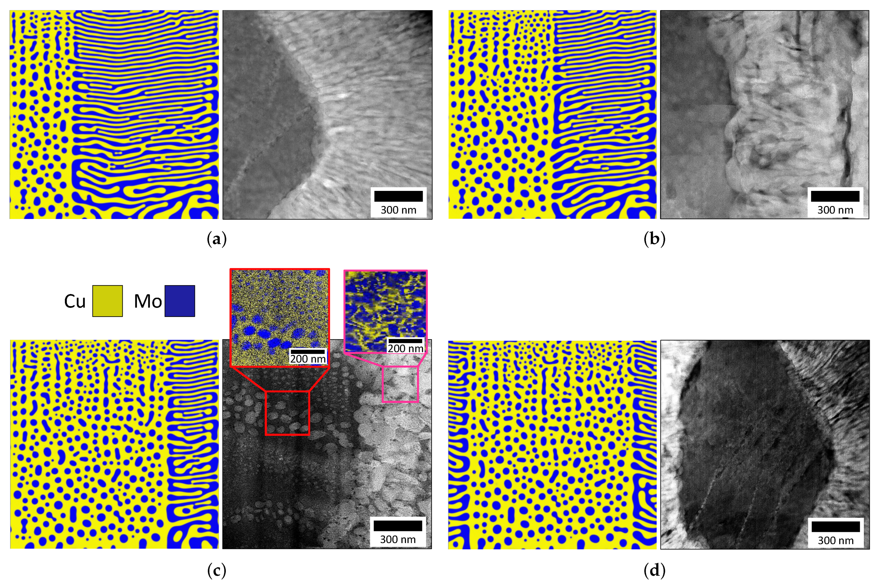
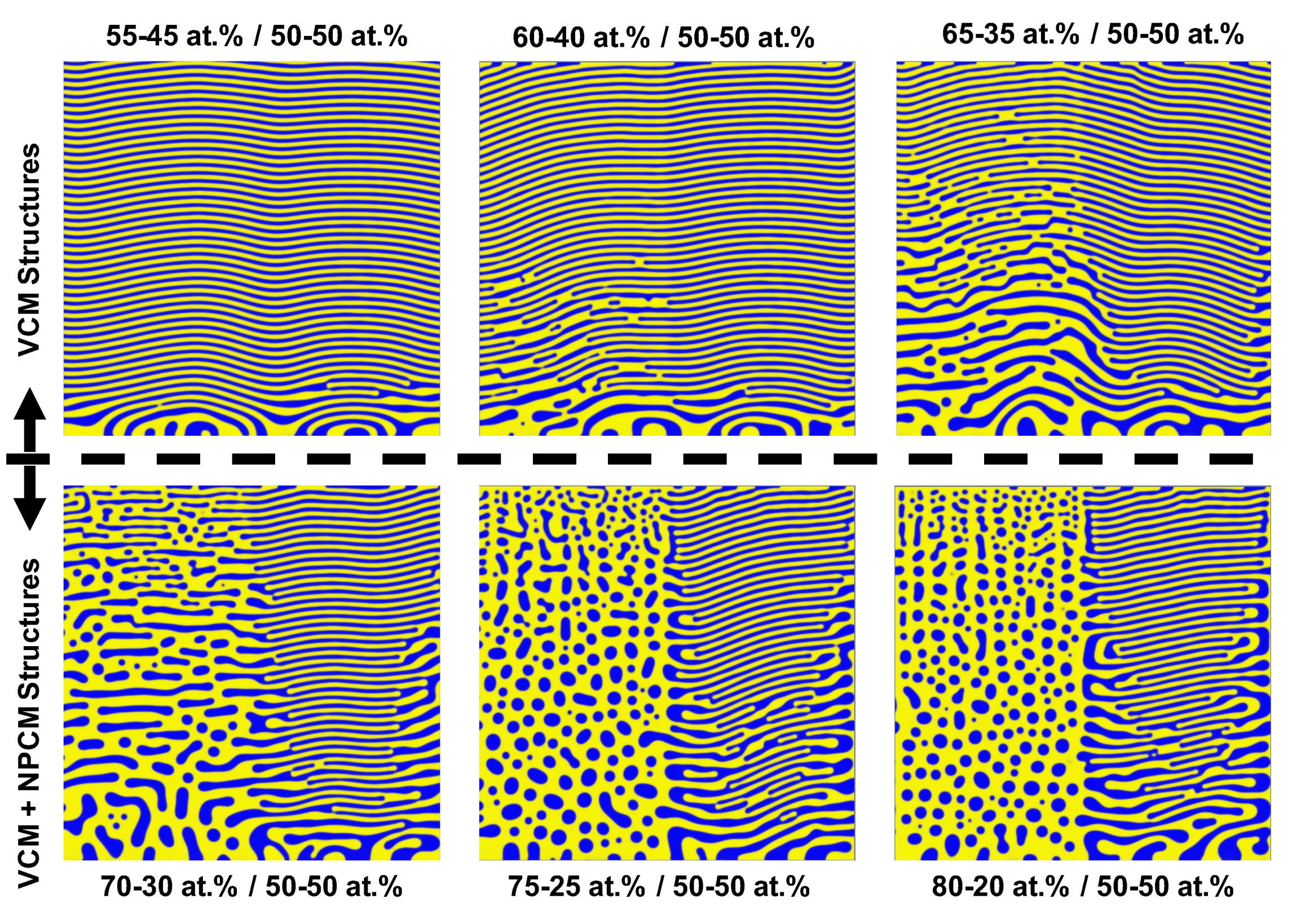
3. Results and Discussion
4. Conclusions
Author Contributions
Funding
Data Availability Statement
Acknowledgments
Conflicts of Interest
Abbreviations
| PVD | physical vapor deposition |
| CM | concentration modulation |
| LCM | lateral concentration modulation |
| VCM | vertical concentration modulation |
| NPCM | nanoprecipitate concentration modulation |
| RCM | random concentration modulation |
| EDS | energy dispersive X-ray spectroscopy |
| HAADF | high angle darkfield |
| STEM | scanning transmission electron microscope |
References
- Heo, T.; Shih, D.; Chen, L.Q. Kinetic pathways of phase transformations in two-phase Ti alloys. Metall. Mater. Trans. A 2014, 45, 3438–3445. [Google Scholar] [CrossRef]
- Derby, B.; Cui, Y.; Baldwin, J.; Misra, A. Effects of substrate temperature and deposition rate on the phase separated morphology of co-sputtered, Cu–Mo thin films. Thin Solid Films 2018, 647, 50–56. [Google Scholar] [CrossRef]
- Thornton, J. Influence of apparatus geometry and deposition conditions on the structure and topography of thick sputtered coatings. J. Vac. Sci. Technol. 1974, 11, 666–670. [Google Scholar] [CrossRef]
- Thompson, C. Stress and grain growth in thin films. Annu. Rev. Mater. Sci. 1990, 20, 245–268. [Google Scholar] [CrossRef]
- Adams, C.; Atzmon, M.; Cheng, Y.T.; Srolovitz, D. Phase separation during co-deposition of Al–Ge thin films. J. Mater. Res. 1992, 7, 653–666. [Google Scholar] [CrossRef] [Green Version]
- Atzmon, M.; Kessler, D.; Srolovitz, D. Phase separation during film growth. J. Appl. Phys. 1992, 72, 442–446. [Google Scholar] [CrossRef] [Green Version]
- Adams, C.; Srolovitz, D.; Atzmon, M. Monte Carlo simulation of phase separation during thin-film codeposition. J. Appl. Phys. 1993, 74, 1707–1715. [Google Scholar] [CrossRef] [Green Version]
- Ankit, K.; Derby, B.; Raghavan, R.; Misra, A.; Demkowicz, M. 3-D phase-field simulations of self-organized composite morphologies in physical vapor deposited phase-separating binary alloys. J. Appl. Phys. 2019, 126, 075306. [Google Scholar] [CrossRef]
- Galdikas, A. Study of nanoclusters growth at initial stages of ultrathin film deposition by kinetic modeling. Appl. Surf. Sci. 2008, 254, 3964–3970. [Google Scholar] [CrossRef]
- Lu, Y.; Wang, C.; Gao, Y.; Shi, R.; Liu, X.; Wang, Y. Microstructure map for self-organized phase separation during film deposition. Phys. Rev. Lett. 2012, 109, 086101. [Google Scholar] [CrossRef] [PubMed] [Green Version]
- Derby, B.; Cui, Y.; Baldwin, J.; Arróyave, R.; Demkowicz, M.; Misra, A. Processing of novel pseudomorphic Cu–Mo hierarchies in thin films. Mater. Res. Lett. 2019, 7, 1–11. [Google Scholar] [CrossRef]
- Kairaitis, G.; Galdikas, A. Modelling of phase structure and surface morphology evolution during compound thin film deposition. Coatings 2020, 10, 1077. [Google Scholar] [CrossRef]
- Stewart, J.; Dingreville, R. Microstructure morphology and concentration modulation of nanocomposite thin-films during simulated physical vapor deposition. Acta Mater. 2020, 188, 181–191. [Google Scholar] [CrossRef]
- Powers, M.; Derby, B.; Shaw, A.; Raeker, E.; Misra, A. Microstructural characterization of phase-separated co-deposited Cu–Ta immiscible alloy thin films. J. Mater. Res. 2020, 35, 1531–1542. [Google Scholar] [CrossRef]
- Powers, M.; Derby, B.; Manjunath, S.; Misra, A. Hierarchical morphologies in co-sputter deposited thin films. Phys. Rev. Mater. 2020, 4, 123801. [Google Scholar] [CrossRef]
- Cui, Y.; Derby, B.; Li, N.; Mara, N.; Misra, A. Suppression of shear banding in high-strength Cu/Mo nanocomposites with hierarchical bicontinuous intertwined structures. Mater. Res. Lett. 2018, 6, 184–190. [Google Scholar] [CrossRef] [Green Version]
- Xie, T.; Fu, L.; Qin, W.; Zhu, J.; Yang, W.; Li, D.; Zhou, L. Self-assembled metal nano-multilayered film prepared by co-sputtering method. Appl. Surf. Sci. 2018, 435, 16–22. [Google Scholar] [CrossRef]
- Stewart, J.; Spearot, D. Phase-field models for simulating physical vapor deposition and grain evolution of isotropic single-phase polycrystalline thin films. Comput. Mater. Sci. 2016, 123, 111–120. [Google Scholar] [CrossRef] [Green Version]
- Herman, E.; Stewart, J.; Dingreville, R. A data-driven surrogate model to rapidly predict microstructure morphology during physical vapor deposition. Appl. Math. Model. 2020, 88, 589–603. [Google Scholar] [CrossRef]
- Oura, K.; Katayama, M.; Zotov, A.; Lifshits, V.; Saranin, A. Elementary Processes at Surfaces II. Surface Diffusion. In Surface Science: An Introduction; Springer: Berlin/Heidelberg, Germany, 2003; pp. 325–356. [Google Scholar]
- Krzanowski, J. Phase formation and phase separation in multiphase thin film hard coatings. Surf. Coat. Technol. 2004, 188, 376–383. [Google Scholar] [CrossRef]
- Borroto, A.; García-Wong, A.; Bruyère, S.; Migot, S.; Pilloud, D.; Pierson, J.; Mücklich, F.; Horwat, D. Composition-driven transition from amorphous to crystalline films enables bottom-up design of functional surfaces. Appl. Surf. Sci. 2021, 538, 148133. [Google Scholar] [CrossRef]
- Johnson, W. Spinodal decomposition in a small radially stressed sphere. Acta Mater. 2001, 49, 3463–3474. [Google Scholar] [CrossRef]
- Van Aeken, K.; Mahieu, S.; Depla, D. The metal flux from a rotating cylindrical magnetron: A Monte Carlo simulation. J. Phys. D Appl. Phys. 2008, 41, 205307. [Google Scholar] [CrossRef]
- Depla, D.; Leroy, W. Magnetron sputter deposition as visualized by Monte Carlo modeling. Thin Solid Films 2012, 520, 6337–6354. [Google Scholar] [CrossRef]
- Thornton, J.; Hoffman, D. Stress-related effects in thin films. Thin Solid Films 1989, 171, 5–31. [Google Scholar] [CrossRef]
- Petrov, I.; Barna, P.; Hultman, L.; Greene, J. Microstructural evolution during film growth. J. Vac. Sci. Technol. 2003, 21, S117–S128. [Google Scholar] [CrossRef]
- Langer, G.; Erdélyi, G.; Erdélyi, Z.; Csiszár, G. Determination of diffusion coefficients in immiscible systems: CuW as an example. Materialia 2019, 6, 100342. [Google Scholar] [CrossRef]
- Kairaitis, G.; Galdikas, A. Mechanisms and dynamics of layered structure formation during co-deposition of binary compound thin films. Coatings 2020, 10, 21. [Google Scholar] [CrossRef] [Green Version]


Publisher’s Note: MDPI stays neutral with regard to jurisdictional claims in published maps and institutional affiliations. |
© 2021 by the authors. Licensee MDPI, Basel, Switzerland. This article is an open access article distributed under the terms and conditions of the Creative Commons Attribution (CC BY) license (https://creativecommons.org/licenses/by/4.0/).
Share and Cite
Powers, M.; Stewart, J.A.; Dingreville, R.; Derby, B.K.; Misra, A. Compositionally-Driven Formation Mechanism of Hierarchical Morphologies in Co-Deposited Immiscible Alloy Thin Films. Nanomaterials 2021, 11, 2635. https://doi.org/10.3390/nano11102635
Powers M, Stewart JA, Dingreville R, Derby BK, Misra A. Compositionally-Driven Formation Mechanism of Hierarchical Morphologies in Co-Deposited Immiscible Alloy Thin Films. Nanomaterials. 2021; 11(10):2635. https://doi.org/10.3390/nano11102635
Chicago/Turabian StylePowers, Max, James A. Stewart, Rémi Dingreville, Benjamin K. Derby, and Amit Misra. 2021. "Compositionally-Driven Formation Mechanism of Hierarchical Morphologies in Co-Deposited Immiscible Alloy Thin Films" Nanomaterials 11, no. 10: 2635. https://doi.org/10.3390/nano11102635