
Limitations of Thermal Stability Analysis via In-Situ TEM/Heating Experiments


1
Materials Science and Technology, Los Alamos National Lab, Los Alamos, NM 87545, USA
2
Chemical and Materials Engineering, University of Nevada, Reno, NV 89557, USA
3
Energy and Environment Directorate, Pacific Northwest National Laboratory, Richland, WA 99354, USA
*
Author to whom correspondence should be addressed.
Nanomaterials 2021, 11(10), 2541; https://doi.org/10.3390/nano11102541
Submission received: 7 September 2021
/
Revised: 15 September 2021
/
Accepted: 16 September 2021
/
Published: 28 September 2021
(This article belongs to the Special Issue Thermal, Mechanical and Radiation Stability of Nanostructured Metals)
Abstract
:This work highlights some limitations of thermal stability analysis via in-situ transmission electron microscopy (TEM)-annealing experiments on ultrafine and nanocrystalline materials. We provide two examples, one on nanocrystalline pure copper and one on nanocrystalline HT-9 steel, where in-situ TEM-annealing experiments are compared to bulk material annealing experiments. The in-situ TEM and bulk annealing experiments demonstrated different results on pure copper but similar output in the HT-9 steel. The work entails discussion of the results based on literature theoretical concepts, and expound on the inevitability of comparing in-situ TEM annealing experimental results to bulk annealing when used for material thermal stability assessment.
1. Introduction
Microstructural stability assessment of materials exposed to thermal loads is an essential criterion in climbing the technology readiness level and qualifying materials for applications in industry. Possible microstructural instabilities (e.g., grain size growth or recrystallization) can alter the mechanical properties of materials [1,2]. For example, the hardness, toughness and ductility of materials are grain size dependent [3] and understanding the dependency of these properties as a function of grain size is a crucial step to design thermally stable materials for different applications. A class of materials which has demonstrated to offer significant advantages over commercial materials in terms of mechanical properties and radiation resistance (for nuclear industry) is nanocrystalline (NC), with grain sizes below 100 nm, and ultrafine (UF), with grain sizes in the range of 100–500 nm, grained materials [4,5]. NC and UF grained metallic materials are discussed as possible fusion and fission reactor materials, which have different material requirements and operating conditions [6]. However, these materials have to possess thermal stability and avoid recrystallization. For example, in the Demonstration (DEMO) power plant for fusion, the surface temperature of the divertor is designed to be less than the recrystallization temperature of tungsten (a primary candidate as a plasma facing material) [7,8]. Tungsten in the recrystallized conditions is not favorable due to its low strength, low thermal shock resistance and high ductile to brittle transition temperature (DBTT) [9].
As a rapid characterization technique to assess thermal stability of NC and UF grained materials, performing in-situ transmission electron microscopy (TEM)/heating experiments has evolved, where thin specimen (preferably below 100 nm) are heated inside the TEM microscope while observing the changes in morphology. These experiments were used on different materials and the thermal stability of these materials in the pristine conditions and irradiated conditions (for nuclear materials) are concluded in some cases based on the in-situ TEM/heating observations [10,11,12,13,14,15].
In this work, we study two material systems (NC copper, polycrystalline Cu, and NC HT-9 steel) under in-situ TEM/heating and bulk heating (with ex-situ characterization of morphology) and demonstrate differences on how in-situ TEM/heating experiments can show a limited picture of NC materials behavior under thermal loads. The work on these selected materials of some distinct microstructures has allowed one to discuss several mechanisms suggested in literature regarding the stability of NC and UF grained materials in their bulk and thin film forms and clearly elucidate some limitations of in-situ TEM/heating experiments. The goal of this paper is not to reveal the grain growth kinetics in these NC materials, but rather to increase awareness of the limitations of in-situ TEM experiments, discussed from literature concepts, and to elucidate how data analysis of in-situ of this type of experiments should always be compared to ex-situ bulk heating results in some cases.
2. Materials and Methods
In-situ TEM/heating and bulk heating (under vacuum furnace) experiments were performed on pure NC Cu and HT-9 steels. The main elements in the HT-9 steel, which is a ferritic/martensitic steel, were Cr ~12%. 0.5% W, 0.3% V, 1% Mo, 0.55% Ni, 0.25% Si, 0.55% Mn, 0.2% C and the balance was Fe. The NC materials were prepared via large strain machining (LSM) [16] at RT with a zero rake angle and a speed of 115 RPM. The LSM samples were first cut into 3 mm discs and then mechanically polished to ~100 µm thickness. TEM samples of the NC Cu and NC HT-9 were then prepared via electropolishing, the mechanically polished discs, with 10% phosphoric acid/water (at RT) and 5% perchloric acid/methanol (at −30 °C) solutions respectively. For bulk heating, the mechanically polished discs were electropolished for ~10 s to eliminate any possible damage from mechanical polishing. The in-situ TEM heating experiments were performed using a built-in furnace holder and a ramp rate of 23.3 degrees/min to 700 °C (or ramping time of 30 min). Bulk heating experiments were performed inside a vacuum chamber with a similar ramping rate. Investigation of morphologies before and after heating was performed using TEM and electron backscattered diffraction (EBSD). Morphology characterization was performed on thin (<100 nm thickness) and thick (10 s of µms thickness) regions of the TEM samples and on the bulk heated samples.
3. Results
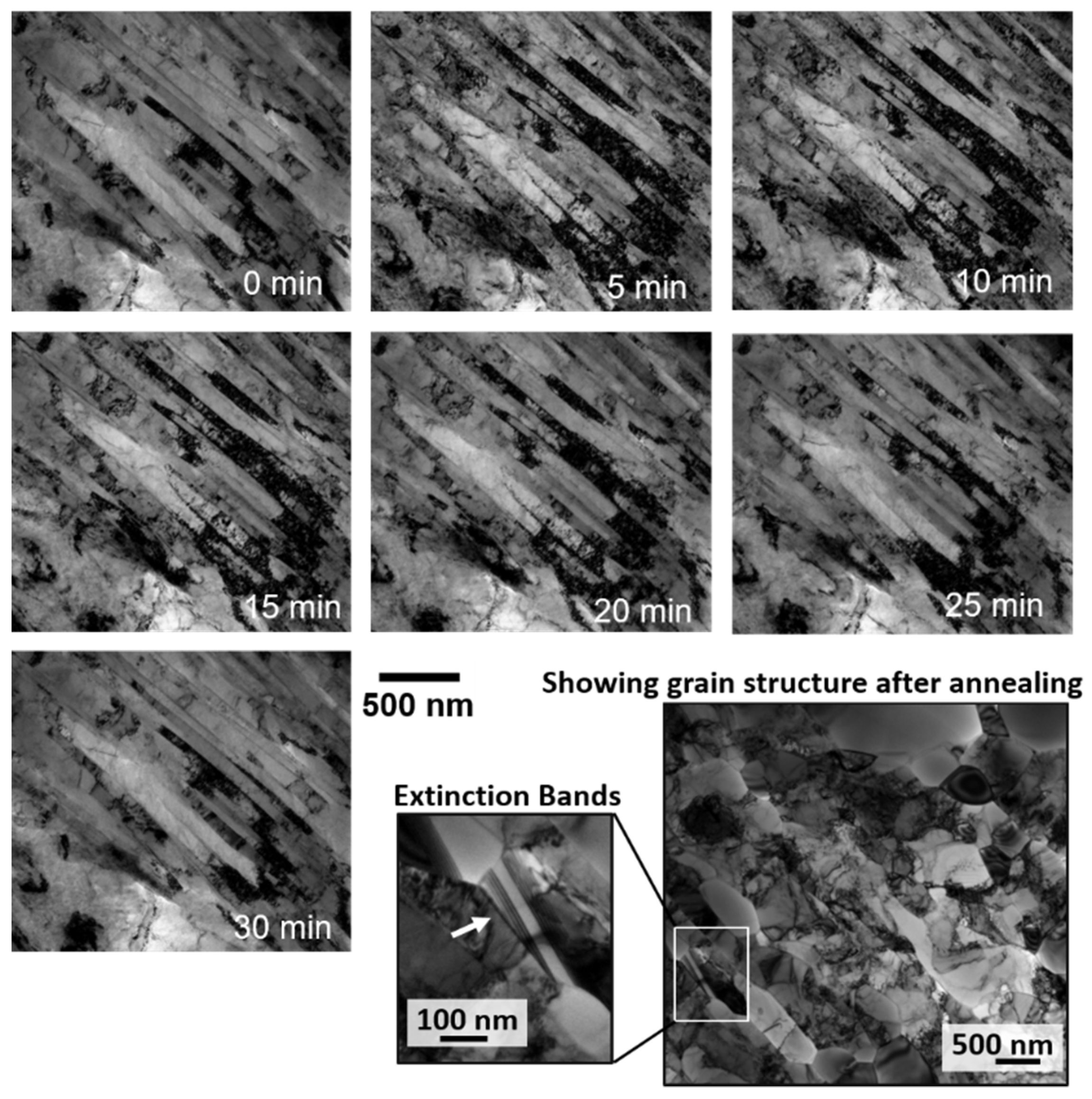
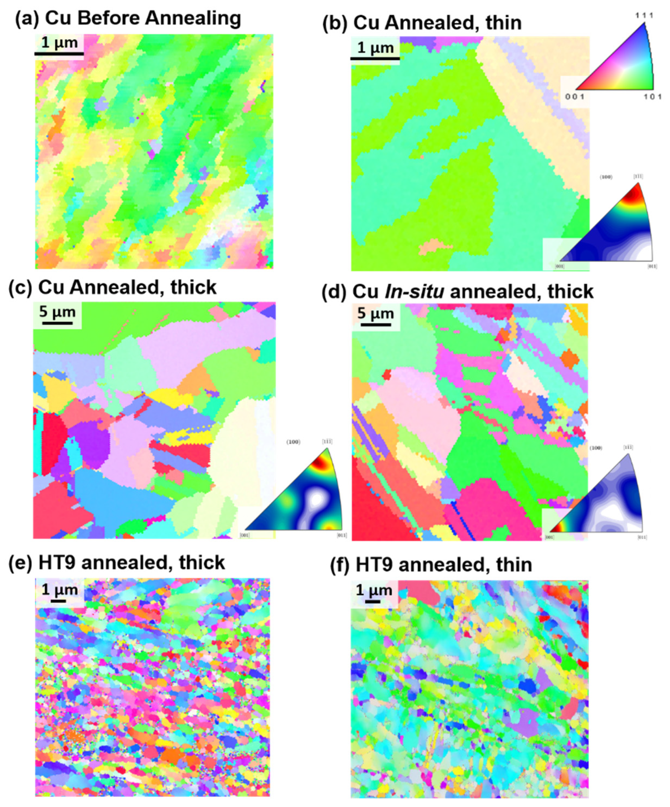
Bright-field micrographs from the in-situ TEM experiments on the NC Cu sample as a function of time are shown in Figure 1. EBSD results are shown in Figure 2. The corresponding change in grain size (calculated from TEM bright-field images or EBSD results) during the course of the experiment is shown in Figure 3. It was evident that the sample microstructures, governed by elongated NC and UF grains, were very thermally stable with a small grain size increase starting to occur at 450 °C (Figure 1 and Figure 3). Under ex-situ heating at 400 °C and for a similar ramping and annealing time, the NC Cu sample showed large grain growth as demonstrated from the EBSD results in Figure 2c (corresponding change in grain size is plotted in Figure 3e). Further examination of the thin and thick regions in the in-situ TEM annealed sample demonstrated grain growth in some parts of the thin region (while other grains showed no grain growth) (Figure 1 and Figure 2b) while the thick regions showed large grain growth (Figure 2d). The corresponding changes in the grain size are plotted in Figure 3d,f respectively.
Similar experiments were performed on NC HT-9 as shown in Figure 2. While some grains showed no grain growth, other grains in the thin area demonstrated moderate grain size increase (Figure 2f and Figure 3h) but similar results and grain sizes to the ex-situ heating (Figure 2e and Figure 3g). Details of the microstructure of the pristine sample (prior to annealing) are shown in ref. [17].
4. Discussion
In the in-situ NC Cu case, where elongated grains showed no grain growth, grain size stagnation occurred. This phenomenon was studied and illustrated in literature [18]. While normal grain growth, or curvature driven grain growth [19,20] is associated with reduction of grain boundary energy, which is dependent on the macroscopic degrees of freedom of the grain boundary, the presence of surfaces in thin films or thin specimens introduces other driving forces for grain growth such as the reduction of surfaces and elastic strain energies [18]. Samples formed through deformation, as is the case in this work, have also stored energy due to deformation (related to grain size distribution) and residual stresses that can induce grain growth. The retarding forces to grain growth driving forces are impurities [21] and grain boundary grooving [22]. In the pure NC Cu, it is expected that grain boundary grooving, formed though the balance of surface and grain boundary forces, is causing grain size stagnation [23] Grain boundary stagnation is expected when the grain size to the film thickness is within the ratio of 1–3 [24] which is the case in the ~100 nm thickness samples used during TEM experiments.
Frost [24] discussed a critical curvature for the grain boundary to pass or climb a groove as:
where and are grain boundary and surface energies respectively and h is the film thickness. It is evident from the equation that decreasing the film thickness is associated with an increase in the critical curvature. As shown in Figure 1 and Figure 2, the elongated grains which showed no grain growth during the experiments are textured and the grain boundaries are of low angle and hence, of low energy which should be associated with lowering the critical curvature. Moreover, these elongated grain boundaries are expected to have low grain boundary velocity, which is proportional to 1/r [25] where r is the radius of curvature, due to the large curvature of the elongated boundaries. Still under ex-situ irradiation, these grain boundaries were not stagnant and evolved into equiaxed large grain boundaries due to the secondary growth [26]. Severe plastically deformed materials are usually expected to possess non-equilibrium boundaries, which are high angle boundaries associated with high density of extrinsic dislocations [27]. While the non-equilibrium state can provide high atomic mobility and lead to lower activation energy for grain boundary migration [28], the recovery of these non-equilibrium grain boundaries to equilibrium counter parts during annealing can lead to an increase in the activation energy and a significant decrease in the driving force and grain boundary mobility, and thus an increase in the grain boundary thermal stability [29]. Based on the EBSD results from the NC Cu prior to annealing (Figure 2), the NC Cu is formed mainly of elongated low angle boundaries while non-equilibrium boundaries, marked by extinction bands formed after grain growth and were associated with the largest grains after the experiments (Figure 1). Therefore, the stagnation of the grain boundaries in the NC Cu is independent of the effect of high angle non-equilibrium boundaries.
After 600 °C in the in-situ experiments, grain growth occurred and at 700 °C (Figure 1 and Figure 2b), large grains were observed adjacent to thermally stable and small grains. This is a result of the secondary recrystallization [26], in which the material’s surfaces play a dominant role during grain growth where the thickness is comparable to the grain size. [18]. Some grains with preferable orientation grow rapidly to minimize their surface energy during growth [18,30]. This leads to bimodal distribution of grains due to the energy anisotropy [18,26] as shown in Figure 3. Images of rapidly grown grains near stagnant grains are shown in Figure 1 and Figure 2. The secondary grain growth is also associated with the development of the sample texture [31,32,33] due to the selective rapid grain growth of certain orientations as mentioned earlier. This is also demonstrated in Figure 2b for the thin area heated in-situ when compared to the ex-situ bulk material results (Figure 2c) or the thick region of the in-situ results (Figure 2d). This is due to the large thickness of the thick area or the ex-situ bulk heated sample where grains are expected to follow normal grain growth.
In the case of the NC HT-9, the morphology of the sample consisted of elongated and equiaxed grains. The in-situ TEM annealing was performed on the equiaxed grains while also observing the elongated grains intermittently. From the in-situ data [17], some grain growth and recrystallization occurred where the recrystallized grains demonstrated further thermal stability. Both the in-situ and the ex-situ annealing lead to similar grain size (Figure 2e,f and Figure 3g,h) and no secondary growth or texture development occurred in the in-situ annealed experiments. This proves the stability of these films in which in-situ TEM truly predicted the material’s thermal stability. Stability of ultrafine grains with impurities are attributed to the impurity drag effect (Zener pressure) [34] which stabilizes the grain and opposes the grain growth driving force [26]. The EDX of the NC HT-9 has demonstrated carbide formation on the grain boundaries and the thermal stability of these grains were attributed to lower dislocation densities and presence of carbides [17]. In a NC pure material case, El-Atwani et al. has shown stable ~100–200 nm grain size NC pure Fe grains up to temperature 600 °C [35]. These results were consistent with other works on bulk NC Fe [36,37] demonstrating another case where in-situ TEM predicted the bulk material behavior. However, it is evident that NC materials that are stable in bulk forms are also stable during in-situ TEM experiments, but the opposite may not be true.
5. Conclusions
The two examples provided in this work and the corresponding comparison and illustration of established theories in literature provide sufficient evidence that vigilant analysis and comparison with bulk heating experiments should be performed to establish kinetics and conclusions regarding thermal stability of NC and UF materials via in-situ TEM/heating experiments, which have to be performed on thin areas that are usually below 100 nm thicknesses. Grain size stagnation and secondary grain growth which can occur in NC and UF materials have to be investigated and if shown to exist, then subsequent conclusions can only be drawn in regards to the thin film form of the investigated material.
Author Contributions
Conceptualization, O.E.-A.; methodology, O.E.-A.; formal analysis, O.E.-A.; investigation, O.E.-A. and H.K.; resources, O.E.-A. and M.E.; data curation, H.K. and C.H.; writing—original draft preparation, O.E.-A.; writing—review and editing, C.H., M.E. and S.A.M.; visualization, C.H.; project administration, O.E.-A.; funding acquisition, O.E.-A. and S.A.M. All authors have read and agreed to the published version of the manuscript.
Funding
This research received no external funding.
Data Availability Statement
The data presented in this study are available within the article itself.
Acknowledgments
This work was performed, in part, at the Center for Integrated Nanotechnologies, an Office of Science User Facility operated for the U.S. Department of Energy (DOE) Office of Science. Research presented in this article was also supported by the Laboratory Directed Research and Development program of Los Alamos National Laboratory under the early career program. CH acknowledges support from the DOE Integrated University Program Graduate Fellowship for this work.
Conflicts of Interest
The authors declare no conflict of interest.
References
- Wang, N.; Wang, Z.; Aust, K.; Erb, U. Effect of grain size on mechanical properties of nanocrystalline materials. Acta Metall. Mater. 1995, 43, 519–528. [Google Scholar] [CrossRef]
- Fujita, H.; Tabata, T. The effect of grain size and deformation sub-structure on mechanical properties of polycrystalline aluminum. Acta Metall. 1973, 21, 355–365. [Google Scholar] [CrossRef]
- Meyers, M.; Mishra, A.; Benson, D. Mechanical properties of nanocrystalline materials. Prog. Mater. Sci. 2006, 51, 427–556. [Google Scholar] [CrossRef]
- Wei, Q.; Jiao, T.; Ramesh, K.; Ma, E.; Kecskes, L.; Magness, L.; Dowding, R.; Kazykhanov, V.; Valiev, R. Mechanical behavior and dynamic failure of high-strength ultrafine grained tungsten under uniaxial compression. Acta Mater. 2006, 54, 77–87. [Google Scholar] [CrossRef]
- Wei, Q.; Zhang, H.; Schuster, B.; Ramesh, K.; Valiev, R.; Kecskes, L.; Dowding, R.; Magness, L.; Cho, K. Microstructure and mechanical properties of super-strong nanocrystalline tungsten processed by high-pressure torsion. Acta Mater. 2006, 54, 4079–4089. [Google Scholar] [CrossRef]
- Zinkle, S.J.; Busby, J. Structural materials for fission & fusion energy. Mater. Today 2009, 12, 12–19. [Google Scholar] [CrossRef]
- Tillack, M.; Raffray, A.; Wang, X.; Malang, S.; Abdel-Khalik, S.; Yoda, M.; Youchison, D. Recent US activities on advanced He-cooled W-alloy divertor concepts for fusion power plants. Fusion Eng. Des. 2011, 86, 71–98. [Google Scholar] [CrossRef]
- Tobita, K.; Nishio, S.; Enoeda, M.; Kawashima, H.; Kurita, G.; Tanigawa, H.; Nakamura, H.; Honda, M.; Saito, A.; Sato, S.; et al. Compact DEMO, SlimCS: Design progress and issues. Nucl. Fusion 2009, 49, 075029. [Google Scholar] [CrossRef]
- Davis, J.; Barabash, V.; Makhankov, A.; Plöchl, L.; Slattery, K. Assessment of tungsten for use in the ITER plasma facing components. J. Nucl. Mater. 1998, 258, 308–312. [Google Scholar] [CrossRef]
- El-Atwani, O.; Hinks, J.A.; Greaves, G.; Allain, J.P.; Maloy, S.A. Grain size threshold for enhanced irradiation resistance in nanocrystalline and ultrafine tungsten. Mater. Res. Lett. 2017, 5, 343–349. [Google Scholar] [CrossRef] [Green Version]
- El-Atwani, O.; Li, N.; Li, M.; Devaraj, A.; Baldwin, J.K.S.; Schneider, M.M.; Sobieraj, D.; Wróbel, J.S.; Nguyen-Manh, D.; Maloy, S.A. Outstanding radiation resistance of tungsten-based high-entropy alloys. Sci. Adv. 2019, 5, eaav2002. [Google Scholar] [CrossRef] [Green Version]
- Du, C.; Jin, S.; Fang, Y.; Li, J.; Hu, S.; Yang, T.; Zhang, Y.; Huang, J.; Sha, G.; Wang, Y.; et al. Ultrastrong nanocrystalline steel with exceptional thermal stability and radiation tolerance. Nat. Commun. 2018, 9, 5389. [Google Scholar] [CrossRef]
- Kacher, J.; Hattar, K.; Robertson, I.M. Initial texture effects on the thermal stability and grain growth behavior of nanocrystalline Ni thin films. Mater. Sci. Eng. A 2016, 675, 110–119. [Google Scholar] [CrossRef] [Green Version]
- Clark, B.G.; Hattar, K.; Marshall, M.T.; Chookajorn, T.; Boyce, B.; Schuh, C.A. Thermal Stability Comparison of Nanocrystalline Fe-Based Binary Alloy Pairs. JOM 2016, 68, 1625–1633. [Google Scholar] [CrossRef]
- Anber, E.A.; Lang, A.C.; Lass, E.A.; Suri, P.K.; D’Antuono, D.S.; Diao, H.; Liaw, P.K.; Taheri, M.L. Thermal Stability of High Entropy Alloys during in Situ TEM Heating. Microsc. Microanal. 2018, 24, 1928–1929. [Google Scholar] [CrossRef] [Green Version]
- Efe, M.; El-Atwani, O.; Guo, Y.; Klenosky, D.R. Microstructure refinement of tungsten by surface deformation for irradiation damage resistance. Scr. Mater. 2014, 70, 31–34. [Google Scholar] [CrossRef]
- El Atwani, H.K.O.; Gigax, J.; Harvey, C.; Aytuna, B.; Efe, M.; Maloy, S. Highly Stable, Ductile and Strong Nanocrystalline HT-9 Steels via Large Strain Machining. Nanomaterials 2021, in press. [Google Scholar]
- Barmak, K.; Eggeling, E.; Kinderlehrer, D.; Sharp, R.; Ta’Asan, S.; Rollett, A.; Coffey, K. Grain growth and the puzzle of its stagnation in thin films: The curious tale of a tail and an ear. Prog. Mater. Sci. 2013, 58, 987–1055. [Google Scholar] [CrossRef]
- Kinderlehrer, D.; Livshits, I.; Ta’Asan, S. A Variational Approach to Modeling and Simulation of Grain Growth. SIAM J. Sci. Comput. 2006, 28, 1694–1715. [Google Scholar] [CrossRef]
- Battaile, C.; Holm, E.; Weiland, H.; Adams, B.; Rollett, A. Grain growth in polycrystalline materials. In Proceedings of the Third International Conference on Grain Growth, Warrendale, PA, USA, 14–19 June 1998; p. 119. [Google Scholar]
- Lücke, K.; Stüwe, H. On the theory of impurity controlled grain boundary motion. Acta Metall. 1971, 19, 1087–1099. [Google Scholar] [CrossRef]
- Mullins, W.W. Theory of Thermal Grooving. J. Appl. Phys. 1957, 28, 333–339. [Google Scholar] [CrossRef]
- Mullins, W. The effect of thermal grooving on grain boundary motion. Acta Metall. 1958, 6, 414–427. [Google Scholar] [CrossRef]
- Frost, H. Microstructural evolution in thin films. Mater. Charact. 1994, 32, 257–273. [Google Scholar] [CrossRef]
- Burke, J.E.; Turnbull, D. Recrystallization and grain growth. Prog. Met. Phys. 1952, 3, 220–292. [Google Scholar] [CrossRef]
- Thompson, C.V. Grain growth in thin films. Annu. Rev. Mater. Res. 1990, 20, 245–268. [Google Scholar] [CrossRef]
- Chen, W.; Xu, J.; Liu, D.; Bao, J.; Sabbaghianrad, S.; Shan, D.; Guo, B.; Langdon, T.G. Microstructural Evolution and Microhardness Variations in Pure Titanium Processed by High-Pressure Torsion. Adv. Eng. Mater. 2020, 22, 1901462. [Google Scholar] [CrossRef]
- Lian, J.; Valiev, R.Z.; Baudelet, B. On the enhanced grain growth in ultrafine grained metals. Acta Metall. Mater. 1995, 43, 4165–4170. [Google Scholar] [CrossRef]
- Valiev, R. Paradoxes of Severe Plastic Deformation. Adv. Eng. Mater. 2003, 5, 296–300. [Google Scholar] [CrossRef]
- Srolovitz, D.J.; Grest, G.S.; Anderson, M.P. Computer simulation of grain growth—V. Abnormal grain growth. Acta Metall. 1985, 33, 2233–2247. [Google Scholar] [CrossRef]
- Glushko, O.; Dehm, G. Initiation and stagnation of room temperature grain coarsening in cyclically strained gold films. Acta Mater. 2019, 169, 99–108. [Google Scholar] [CrossRef] [Green Version]
- Sonnweber-Ribic, P.; Gruber, P.A.; Dehm, G.; Strunk, H.P.; Arzt, E. Kinetics and driving forces of abnormal grain growth in thin Cu films. Acta Mater. 2012, 60, 2397–2406. [Google Scholar] [CrossRef]
- Ellis, E.; Chmielus, M.; Lin, M.-T.; Joress, H.; Visser, K.; Woll, A.; Vinci, R.; Brown, W.L.; Baker, S.P. Driving forces for texture transformation in thin Ag films. Acta Mater. 2016, 105, 495–504. [Google Scholar] [CrossRef] [Green Version]
- Nes, E.; Ryum, N.; Hunderi, O.J.A.M. On the Zener drag. Acta Metall. 1985, 33, 11–22. [Google Scholar] [CrossRef]
- El-Atwani, O.; Nathaniel, J.E.; Leff, A.C.; Hattar, K.; Taheri, M.L. Direct Observation of Sink-Dependent Defect Evolution in Nanocrystalline Iron under Irradiation. Sci. Rep. 2017, 7, 1836. [Google Scholar] [CrossRef] [Green Version]
- Darling, K.; VanLeeuwen, B.; Semones, J.; Koch, C.; Scattergood, R.; Kecskes, L.; Mathaudhu, S. Stabilized nanocrystalline iron-based alloys: Guiding efforts in alloy selection. Mater. Sci. Eng. A 2011, 528, 4365–4371. [Google Scholar] [CrossRef]
- Malow, T.; Koch, C.J.A.M. Grain growth in nanocrystalline iron prepared by mechanical attrition. Acta Mater. 1997, 45, 2177–2186. [Google Scholar] [CrossRef]
Figure 1.
TEM micrographs of in-situ annealing of NC Cu from 0 to 700 °C in 30 min. The bottom right image shows a lower magnification image of a grain structure (after annealing) in a different thin area of the sample with some non-equilibrium grains marked by extinction bands.
Figure 1.
TEM micrographs of in-situ annealing of NC Cu from 0 to 700 °C in 30 min. The bottom right image shows a lower magnification image of a grain structure (after annealing) in a different thin area of the sample with some non-equilibrium grains marked by extinction bands.

Figure 2.
Inverse pole figure EBSD maps for (a–c) LSM Cu before and after annealing in thick and thin regions. (d) LSM bulk Cu material annealed. (e,f) HT-9 annealed in thick and thin regions.
Figure 2.
Inverse pole figure EBSD maps for (a–c) LSM Cu before and after annealing in thick and thin regions. (d) LSM bulk Cu material annealed. (e,f) HT-9 annealed in thick and thin regions.

Figure 3.
Grain size histograms for (a–d) in-situ Cu annealing as shown in Figure 2, with (d) showing grain size after annealing in a larger area of the thin area in the sample. (e,f) show Cu annealed corresponding to the EBSD (c,d) in Figure 2 respectively. (g,h) HT9 annealed corresponding to (e,f) in Figure 2 respectively.

Publisher’s Note: MDPI stays neutral with regard to jurisdictional claims in published maps and institutional affiliations. |
© 2021 by the authors. Licensee MDPI, Basel, Switzerland. This article is an open access article distributed under the terms and conditions of the Creative Commons Attribution (CC BY) license (https://creativecommons.org/licenses/by/4.0/).
Share and Cite
MDPI and ACS Style
El-Atwani, O.; Kim, H.; Harvey, C.; Efe, M.; Maloy, S.A. Limitations of Thermal Stability Analysis via In-Situ TEM/Heating Experiments. Nanomaterials 2021, 11, 2541. https://doi.org/10.3390/nano11102541
AMA Style
El-Atwani O, Kim H, Harvey C, Efe M, Maloy SA. Limitations of Thermal Stability Analysis via In-Situ TEM/Heating Experiments. Nanomaterials. 2021; 11(10):2541. https://doi.org/10.3390/nano11102541
Chicago/Turabian StyleEl-Atwani, Osman, Hyosim Kim, Cayla Harvey, Mert Efe, and Stuart A. Maloy. 2021. "Limitations of Thermal Stability Analysis via In-Situ TEM/Heating Experiments" Nanomaterials 11, no. 10: 2541. https://doi.org/10.3390/nano11102541
Note that from the first issue of 2016, this journal uses article numbers instead of page numbers. See further details here.