
TiNi-Based Material with Shape-Memory Effect for Surgical Treatment of Diseases of Small Intestine in Newborn and Young Children
 , ,
, ,  , and
, and
Abstract
:1. Introduction
2. Materials and Methods
3. Results
3.1. Macro- and Microstructural Features of TiNi Wire Material
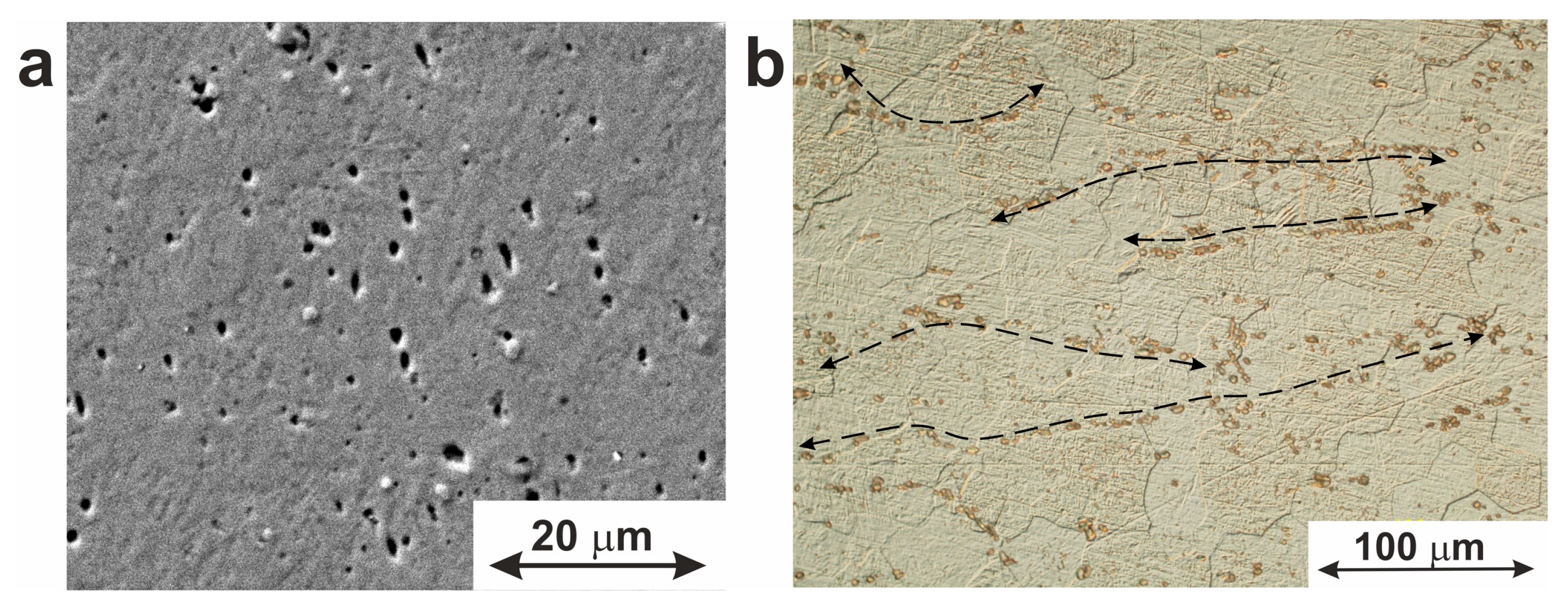
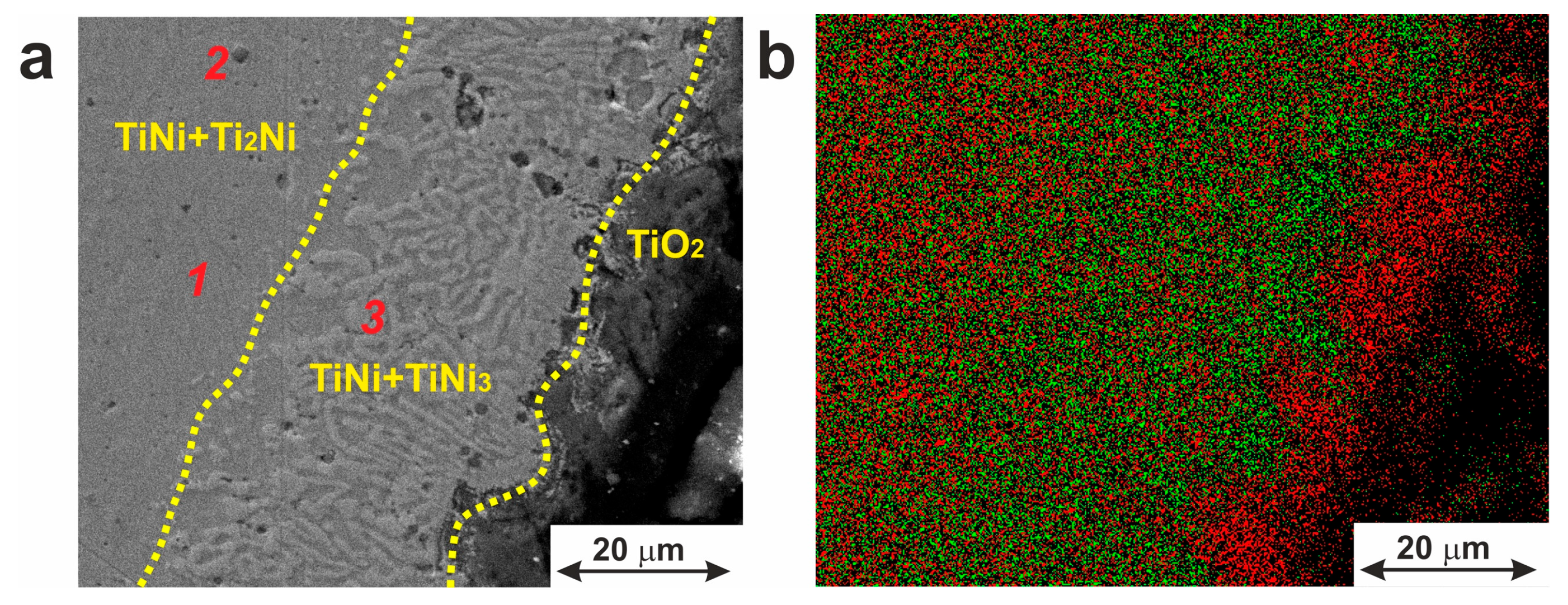
3.1.1. Secondary Phase Inclusions
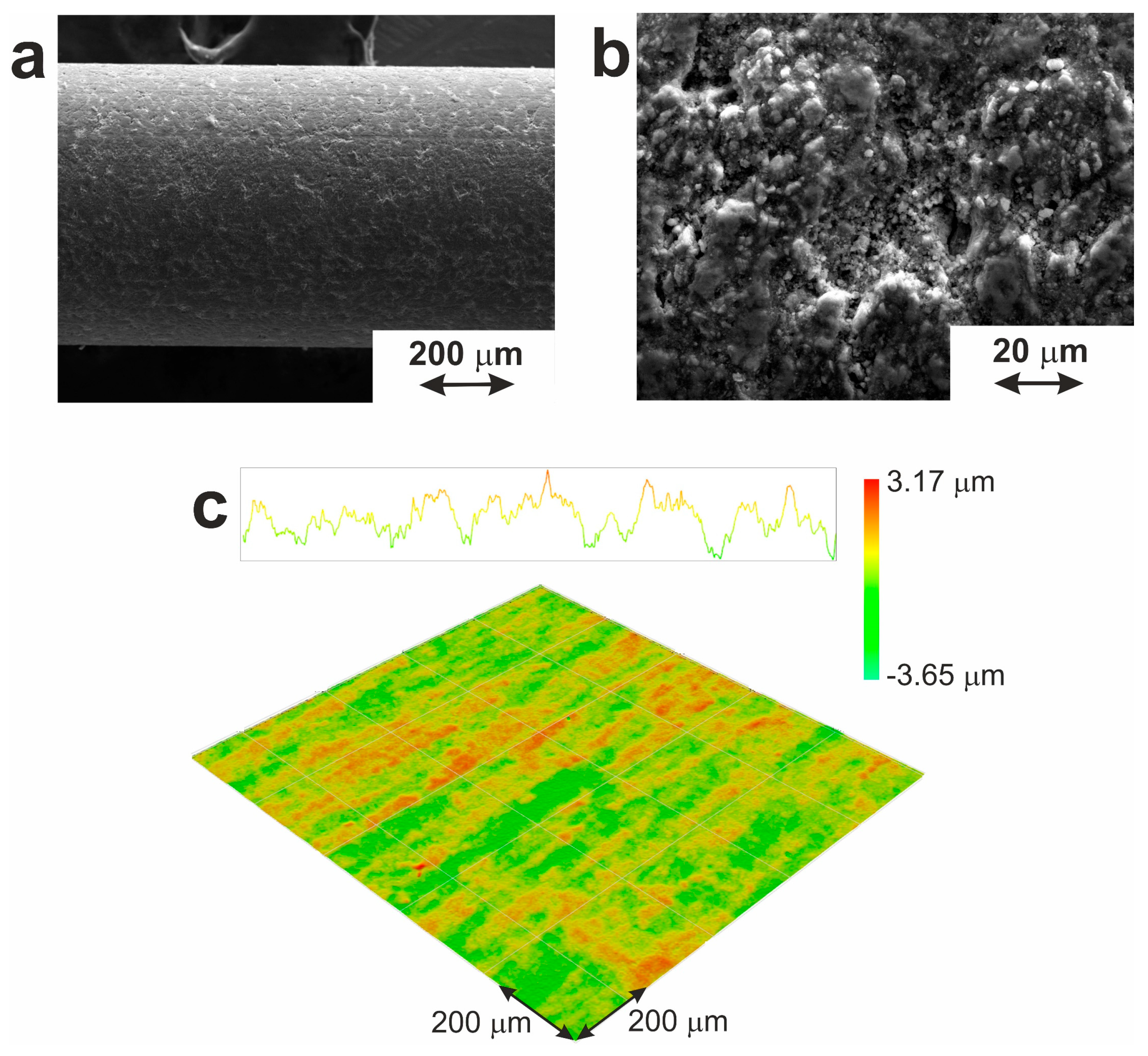
3.1.2. Superficial Layers
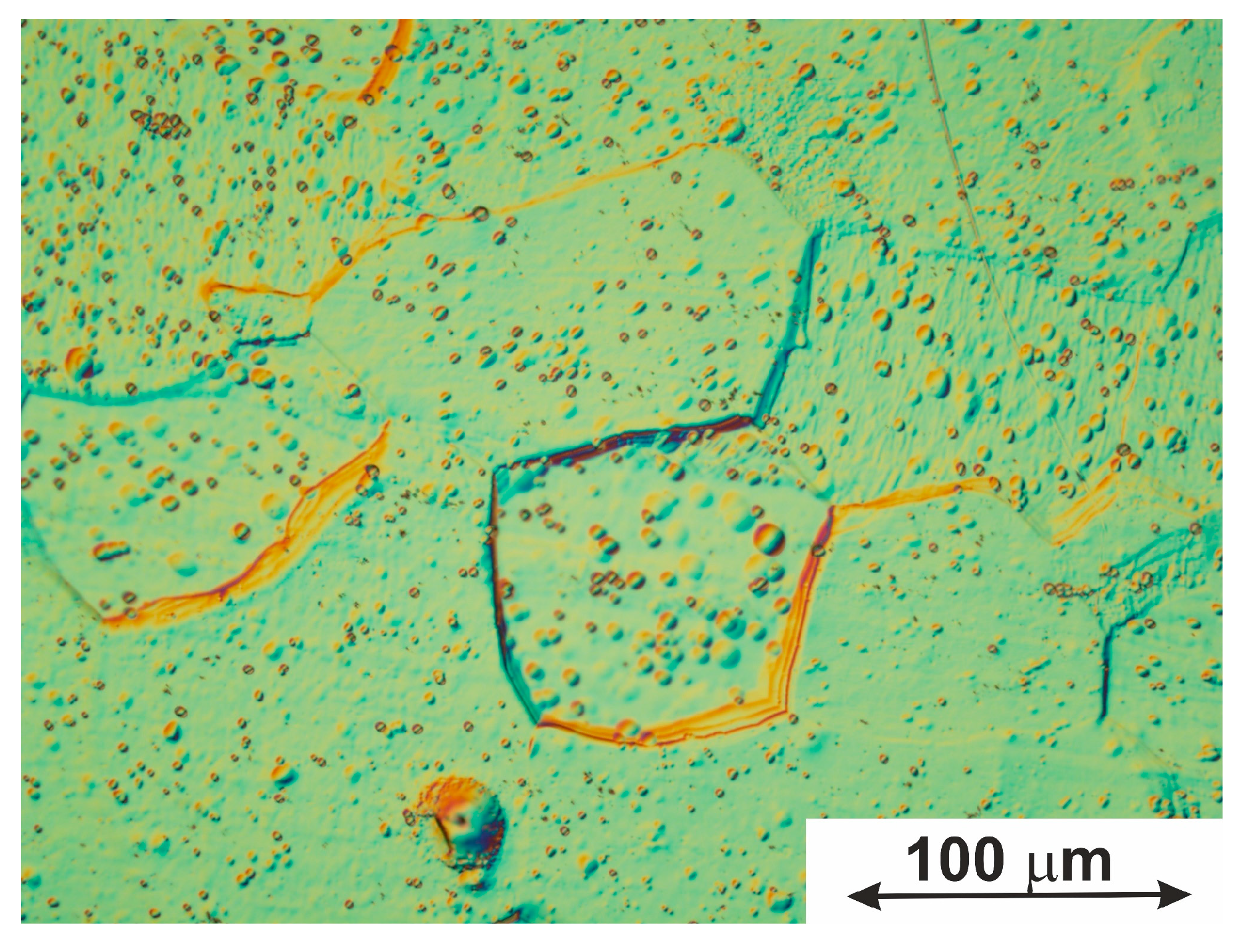
3.1.3. Grain Boundaries
3.2. MTs and Shape-Memory Effects
3.3. Physical–Mechanical Properties
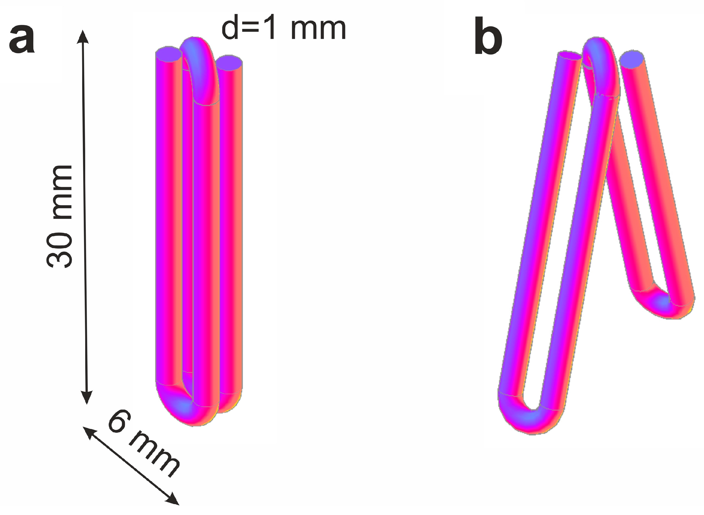
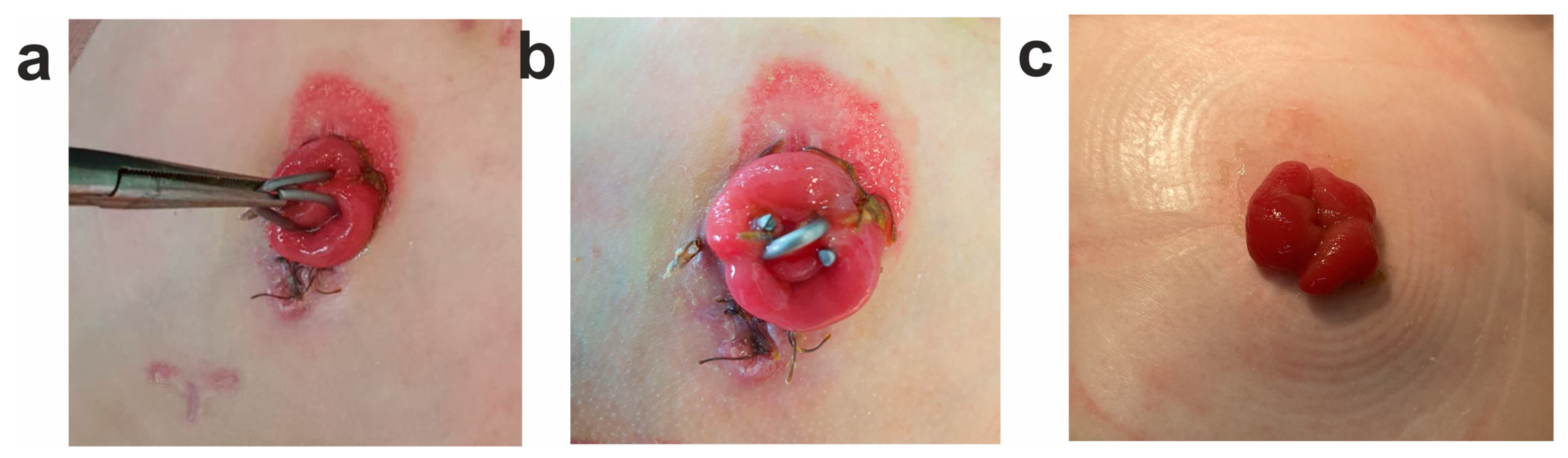
3.4. Application of TiNi-Based Material for Mikulicz Double-Barreled Enterostomy
4. Conclusions
Author Contributions
Funding
Data Availability Statement
Acknowledgments
Conflicts of Interest
References
- Jani, J.M.; Leary, M.; Subic, A.; Gibson, M.A. A review of shape memory alloy research, applications and opportunities. Mater. Des. 2014, 56, 1078–1113. [Google Scholar] [CrossRef]
- Elahinia, G.S.; Hashemi, M.H.; Tabesh, M.; Bhaduri, S.B. Manufacturing and processing of NiTi implants: A review. Prog. Mater. Sci. 2012, 57, 911–946. [Google Scholar] [CrossRef]
- Benčina, M.; Mavrič, T.; Junkar, I.; Bajt, A.; Krajnović, A.; Lakota, K.; Iglič, A. The importance of antibacterial surfaces in biomedical applications. Adv. Biomembr. Lipid Self-Assem. 2018, 28, 115–165. [Google Scholar]
- Margan, N.B. Medical shape memory alloy applications—The market and its products. Mater. Sci. Eng. A 2004, 378, 16–23. [Google Scholar] [CrossRef]
- Ilyin, A.A.; Gusev, D.E.; Chernysheva, Y.V.; Karpov, V.N.; Roschina, E.A. Investigation of corrosion resistance of biomaterials based on titanium and titanium nickelide. Technol. Light Alloy. 2007, 3, 123–130. (In Russian) [Google Scholar]
- Pelton, A.R.; Stöckel, D.; Duerig, T.W. Medical Uses of Nitinol. Mater. Sci. Forum 2000, 327–328, 63–70. [Google Scholar] [CrossRef]
- Kapoor, D. Nitinol for Medical Applications: A Brief Introduction to the Properties and Processing of Nickel Titanium Shape Memory Alloys and their Use in Stents. Johns Matthey Technol. Rev. 2017, 61, 66–76. [Google Scholar] [CrossRef]
- Marandi, L.; Sen, I. In-vitro mechanical behavior and high cycle fatigue characteristics of NiTi-based shape memory alloy wire. Int. J. Fatigue 2021, 148, 106226. [Google Scholar] [CrossRef]
- Kumar, S.; Bikram, P.; Biswajit, B.; Rakesh, S.; Deepak, R.; Behera, A.S. A review on NiTi alloys for biomedical applications and their biocompatibility. Mater. Today 2020, 33, 5548–5551. [Google Scholar]
- Anikeev, S.G.; Artyukhova, N.V.; Shabalina, A.V.; Kulinich, S.A.; Hodorenko, V.N.; Kaftaranova, M.I.; Promakhov, V.V.; Gunter, V.E. Preparation of porous TiNi-Ti alloy by diffusion sintering method and study of its composition, structure and martensitic transformations. J. Alloys Compd. 2022, 900, 163559. [Google Scholar] [CrossRef]
- Kaftaranova, M.I.; Hodorenko, V.N.; Anikeev, S.G.; Artyukhova, N.V.; Shabalina, A.V.; Gunter, V.E. Investigation of the Effect of Copper Addition on Physical and Mechanical Properties of TiNi-Cu Porous Alloy. Metals 2022, 12, 1696. [Google Scholar] [CrossRef]
- Liu, M.; Li, J.; Zhang, Y.X. Recent advances in corrosion research of biomedical NiTi shape memory alloy. Rare Met. Mat. Eng. 2021, 50, 4165–4173. [Google Scholar]
- Wang, J.; Wang, T.; Dong, S.; Kang, X.; Zhao, S.; Shi, H.; Gao, B.; Ma, S.; Liu, M.; Niu, L.; et al. The effect of Cu-doping on the corrosion behavior of NiTi alloy arch wires under simulated clinical conditions. Mater. Res. Express 2021, 8, 016537. [Google Scholar] [CrossRef]
- Kulkova, S.E.; Bakulin, A.V.; Hu, Q.-M.; Yang, R. Study of Nickel Segregation at the TiNi-Titanium Oxide Interface. Mater. Sci. Forum 2013, 738–739, 269–273. [Google Scholar] [CrossRef]
- Kulkova, S.E.; Bakulin, A.V.; Hu, Q.-M.; Yang, R. First-principles investigations of oxygen adsorption at TiNi surface and the TiO2/TiO-TiNi interface. Phys. B Condens. Matter 2013, 426, 118–126. [Google Scholar] [CrossRef]
- Dong, X.; Fei, Y.; Wang, J.B.; Su, Y.Y.; Jing, F.J.; Leng, Y.X.; Huang, N. Deformation behavior of TiO2 films deposited on NiTi shape memory alloy after tensile and water-bath heating tests. Surf. Coat. Technol. 2021, 416, 127151. [Google Scholar] [CrossRef]
- Dong, B.; Wu, F.; Alajmi, Z.; Zhang, C.; Fu, T.; Ge, Y. Sol–gel derived Ta-containing TiO2 films on surface roughened NiTi alloy. Rare Met. 2014, 33, 21–27. [Google Scholar] [CrossRef]
- Rudolf, R.; Stambolíc, A.; Kocijan, A. Atomic Layer Deposition of aTiO2 Layer on Nitinol and Its Corrosion Resistance in a Simulated Body Fluid. Metals 2021, 11, 659. [Google Scholar] [CrossRef]
- Wang, H.R.; Liu, F.; Zhang, Y.P.; Yu, D.Z.; Wang, F.P. Preparation and properties of titanium oxide film on NiTi alloy by micro-arc oxidation. Appl. Surf. Sci. 2011, 257, 5576–5580. [Google Scholar] [CrossRef]
- Saric, I.; Peter, R.; Piltaver, I.K.; Jelovica Badovinac, I.; Salamon, K.; Petravic, M. Residual chlorine in TiO2 films grown at low temperatures by plasma enhanced atomic layer deposition. Thin Solid Films 2017, 628, 142–147. [Google Scholar] [CrossRef]
- Piltaver, I.K.; Peter, R.; Šarić, I.; Salamon, K.; Jelovica Badovinac, I.; Koshmak, K.; Nannarone, S.; Delǎc, M.I.; Petravić, M. Controlling the grain size of polycrystalline TiO2 films grown by atomic layer deposition. Appl. Surf. Sci. 2017, 419, 564–572. [Google Scholar] [CrossRef]
- Vokoun, D.; Racek, J.; Kaderavek, L.; Kei, C.C.; Yu, Y.S.; Klimša, L.; Šittner, P. Atomic Layer-Deposited TiO2 Coatings on NiTi Surface. J. Mater. Eng. Perform. 2018, 27, 572–579. [Google Scholar] [CrossRef]
- Tao, F.; Hongwei, L.; Feng, W.; Wen, L.; Jianmin, S. One-Step Synthesis of TiO2-Hydroxyapatite Nano-films on NiTi Alloy by Hydrothermal Method. Rare Met. Mater. Eng. 2016, 45, 1128–1131. [Google Scholar] [CrossRef] [Green Version]
- Gunther, V.E.; Khodorenko, V.N.; Chekalkin, T.L. Medical Materials with Shape Memory. In Medical Materials and Shape Memory Implants, 1st ed.; NPP «MIC»: Tomsk, Russia, 2011; p. 534. (In Russian) [Google Scholar]
- Gunther, V.E.; Khodorenko, V.N.; Yasenchuk, Y.F. Titanium Nickelide: New Generation Medical Material; NPP «MIC»: Tomsk, Russia, 2006; p. 296. (In Russian) [Google Scholar]
- Otsuka, K.; Ren, X. Physical metallurgy of TiNi based shape memory alloys. Prog. Mater Sci. 2005, 50, 511–678. [Google Scholar] [CrossRef]
- Safavi, M.S.; Bordbar-Khiabani, A.; Walsh, F.C.; Mozafari, M.; Khalil-Allafi, J. Surface modified NiTi smart biomaterials: Surface engineering and biological compatibility. Curr. Opin. Biomed. Eng. 2023, 25, 100429. [Google Scholar] [CrossRef]
- Fili, P.; Lausmaa, J.; Musialekc, J.; Mazaneca, K. Structure and surface of TiNi human implants. Biomaterials 2001, 22, 2131–2138. [Google Scholar] [CrossRef]
- Muhamedov, M.; Kulbakin, D.; Gunther, V.; Choynzonov, E.; Chekalkin, T.; Hodorenko, V. Sparing surgery with the use of TiNi-based endografts in larynx cancer patients. J. Surg. Oncol. 2015, 111, 231–236. [Google Scholar] [CrossRef]
- Mustafa, S.F.; Evans, P.L.; Bocca, A.; Patton, D.W.; Sugar, A.W.; Baxter, P.W. Customized titanium reconstruction of post-traumatic orbital wall defects: A review of 22 cases. Int. J. Oral Maxillofac. Surg. 2011, 40, 1357–1362. [Google Scholar] [CrossRef]
- Zheravin, A.; Gyunter, V.; Anisenya, I.; Garbukov, E.; Zhamgaryan, G.; Bogoutdinova, A. Reconstruction of the chest wall using titanium-nickelid for cancer patients. Sib. J. Oncol. 2015, 1, 31–37. (In Russian) [Google Scholar]
- Dambaev, G.C.; Topolnitsky, E.B.; Sokolovich, E.G.; Gunter, V.E.; Khodorenko, V.N. Working out and results of application of the method of bronchus stump closure by TiNi implants. Sib. Med. J. 2009, 6, 78–81. (In Russian) [Google Scholar]
- Radkevich, A.A.; Gantimurov, A.G.; Zhiglov, N.G.; Podgorny, V.Y.; Zhiglov, A.N.; Gunther, V.E. Application of TiNi Dental Implants with Permeable Porosity in Patients Rehabilitation with Different Adentia Options. KnE Mater. Sci. 2017, 2, 211–218. [Google Scholar] [CrossRef] [Green Version]
- Leimanchenko, P.I.; Aliev, V.F.; Azizov, S.B.; Krutskikh, A.G. The evolution of research projects of nickelid titanium devices for creating compressive inter-intestinal anastomoses. Clin. Med. J. 2016, 18, 42–47. (In Russian) [Google Scholar]
- Gunther, V.E.; Khodorenko, V.N.; Chekalkin, T.L. Problems of biocompatibility of metallic materials. Implant. Shape Mem. 2011, 1–2, 5–16. (In Russian) [Google Scholar]
- Ziganshin, R.V.; Gunter, W.E.; Gibert, B.K. Compression anastomoses in gastrointestinal surgery performed with a shape memory alloy device. Surgery 1990, 8, 115–120. (In Russian) [Google Scholar]
- Sitko, L.A.; Lysov, A.V.; Ignachik, S.V.; Konev, V.P. Compression intestinal anastomoses using metals with “shape memory” in experiment. Top. Quest. Pediatr. Surg. 1994, 1, 19–20. (In Russian) [Google Scholar]
- Dambaev, G.C.; Solovyov, M.M.; Fatyushina, O.A.; Avdoshina, E.A. Use of titanium nickelide devices in abdominal surgery. Issues Reconstr. Plast. Surg. 2017, 1, 53–56. (In Russian) [Google Scholar]
- Ziganshin, R.V. New technology of compression anastomosis creation in gastrointestinal surgery by superelastic implants with shape memory: Monograph. Sci. Tech. Transl. 2000, 174. (In Russian) [Google Scholar]
- Bisaliev, B.N.; Tsap, N.A.; Tusupkaliev, A.B.; Dosmagambetov, S.P.; Jalmukhanbetov, K.K.; Grzhibovsky, A.M. Application of magnetic-compression intestinal anastomosis in the treatment of children with enterostomies. Nov. Khir. 2020, 28, 46–52. [Google Scholar] [CrossRef]
- Akselrov, M.A. First experience of compression delayed anastomosis during resection of the intestine in peritonitis in children. Pediatr. Surg. 2010, 4, 51–52. (In Russian) [Google Scholar]
- Seidinov, S.M.; Zhunisov, M.S.; Tulezhanov, N.K.; Moldaliev, I.S.; Shaymerdenov, L.A.; Zhunissov, B.K.; Ashirbayeva, J.M. Creation of interintestinal anastomoses using permanent magnets in the complex surgical treatment of children with intestinal stoma. Surgery 2015, 5, 45–50. (In Russian) [Google Scholar]
- Liu, S.Q. Magnetic compression anastomosis for rectal atresia following necrotizing enterocolitis: A case report. Medicine 2020, 99, e23613. [Google Scholar] [CrossRef]
- Balagansky, D.A.; Karavaev, A.V.; Osipkin, V.G.; Vedernikov, V.A.; Slizovsky, G.V.; Gunter, V.E. Application of compression devices from titanium nickelide with shape memory in the treatment of intestinal obstruction in childhood. Med. Kuzbass 2007, 1, 12–13. (In Russian) [Google Scholar]
- Ivanov, S.D.; Slizovsky, G.V.; Shikunova, Y.V.; Pogorelko, V.G.; Balagansky, D.A.; Yushmanova, A.B.; Gunter, V.E.; Khodorenko, V.N.; Anikeev, S.G. Bilateral enterostomy with compression anastomosis in newborns and infants. Russ. Bull. Pediatr. Surg. Anesthesiol. Intensive Care Med. 2021, 11, 463–474. (In Russian) [Google Scholar] [CrossRef]
- Gulyaev, A.P. Metal Science; Metallurgy: Moscow, Russia, 1977; p. 648. (In Russian) [Google Scholar]
- Baranova, L.V.; Demina, E.L. Metallographic Etching of Metals and Alloys; Metallurgiya: Moscow, Russia, 1986; p. 256. (In Russian) [Google Scholar]
- Bramfitt, B.L.; Benscoter, A.O. Metallographer’s Guide: Practices and Procedures for Irons and Steel; ASTM International: Novelty, OH, USA, 2012; pp. 169–202. [Google Scholar]
- Dindo, D.; Demartines, N.; Clavien, P.A. Classification of surgical complications: A new proposal with evaluation in a cohort of 6336 patients and results of a survey. Ann Surg. 2004, 240, 205–213. [Google Scholar] [CrossRef] [PubMed]
- Pushin, V.G. Titanium Nickelide Alloys with Shape Memory Effect: Part. I. Structure, Phase Transformations, and Properties; Ural. Otd. Ross. Akad. Nauk: Ekaterinburg, Russia, 2006; p. 414. (In Russian) [Google Scholar]
- Panchenko, E.Y.; Chumlyakov, Y.I.; Kireeva, I.V.; Ovsyannikov, A.V.; Sehitoglu, H.; Karaman, I.; Maier, Y.H.J. Effect of dispersed Ti3Ni4 particles on martensitic transformations in titanium nickelide single crystals. Phys. Met. Metallogr. 2008, 106, 577–589. [Google Scholar] [CrossRef]
- Zhu, L.; Trepanier, C.; Fino, J.; Pelton, A.R. Oxidation of nitinol and its effect on corrosion resistance. In Proceedings of the ASM Materials & Processes for Medical Device Conference, Anaheim, CA, USA, 8–10 September 2003; pp. 156–161. [Google Scholar]
- Rudskoy, A.I.; Lunev, V.A.; Shaboldo, O.P. Drawing: Teaching Medium; Publishing House of Polytechnic University: St. Petersburg, Russia, 2011; 126p. (In Russian) [Google Scholar]
- Alla, R.K.; Ginjupalli, K.; Upadhya, N.; Shammas, M.; Ravi, R.K.; Sekhar, R. Surface roughness of implants: A review. Trends Biomater. Artif. Organs 2011, 25, 112–118. [Google Scholar]
- Osman, R.B.; Swain, M.V. A critical review of dental implant materials with an emphasis on titanium versus zirconia. Materials 2015, 8, 932–958. [Google Scholar] [CrossRef] [PubMed] [Green Version]
- Rausch, M.A.; Shokoohi-Tabrizi, H.; Wehner, C.; Pippenger, B.E.; Wagner, R.S.; Ulm, C.; Moritz, A.; Chen, J.; Andrukhov, O. Impact of implant surface material and microscale roughness on the initial attachment and proliferation of primary human gingival fibroblasts. Biology 2021, 10, 356. [Google Scholar] [CrossRef]
- Ungersbijck, A.; Pohler, O.E.M.; Perrin, S.M. Evaluation of soft tissue reactions at the interface of titanium limited contact dynamic compression plate implants with different surfacetreatments: An experimental sheep study. Biomaterials 1996, 17, 797–806. [Google Scholar] [CrossRef]
- Razov, A. Application of Titanium Nickelide–Based Alloys in Engineering. Phys. Met. Metallogr. 2004, 97, 97–126. [Google Scholar]
- Kasimtsev, A.V.; Markova, G.V.; Volodko, S.S.; Yudin, S.N.; Karpov, B.V.; Alimov, I.A. Powder Titanium Nickelide: Technology and Properties. Russ. Metall. 2020, 11, 1267–1275. [Google Scholar] [CrossRef]
- Qiu, H.; Si, Z.; Luo, Y.; Feng, P.; Wu, X.; Hou, W.; Zhu, Y.; Chan-Park, M.B.; Xu, L.; Huang, D. The mechanisms and the applications of antibacterial polymers in surface modification on medical devices. Front. Bioeng. Biotechnol. 2020, 8, 910. [Google Scholar] [CrossRef] [PubMed]
- Glaser, A.M.; Shakhpazov, E.K. Dimensional effect during martensite transformation. Mater. Sci. 2007, 12, 3–9. [Google Scholar]
- Kaybyshev, V.G.; Valiev, R.Z.; Tsenev, N.K. Influence of the state of grain boundaries on superplastic flow. Dokl. Math. 1984, 278, 93–97. [Google Scholar]
- Valiev, R.Z.; Tsenev, N.K.; Kaybyshev, M.M. Influence of grain boundary structure on the development of superplastic deformation mechanisms of aluminum alloys. Phys. Met. Metall. 1990, 10, 191–196. [Google Scholar]
- Gleiter, H. Our thoughts are ours, their ends none of our own: Are there ways to synthesize materials beyond the limitations of today? Acta Mater. 2008, 56, 5875–5893. [Google Scholar] [CrossRef]
- Pineau, A.; Benzerga, A.A.; Pardoen, T. Failure of metals III: Fracture and fatigue of nanostructured metallic materials. Acta Mater. 2016, 107, 508–544. [Google Scholar] [CrossRef] [Green Version]
- Shi, X.; Cui, L.; Jiang, D.; Yu, C.; Guo, F.; Yu, M.; Ren, Y.; Liu, Y. Grain size effect on the R phase transformation of nanocrystalline NiTi shape memory alloys. J. Mater. Sci. 2014, 49, 4643–4647. [Google Scholar] [CrossRef] [Green Version]
- Gil, F.; Manero, J.; Planell, J. Effect of grain size on the martensitic transformation in NiTi alloy. J. Mat. Sci. 1995, 30, 2526–2530. [Google Scholar] [CrossRef]
- Ryklina, E.P.; Polyakova, K.; Tabachkova, N.Y.; Resnina, N.; Prokoshkin, S.D. Effect of B2 austenite grain size and aging time on microstructure and transformation behavior of thermomechanically treated titanium nickelide. J. Alloys Compd. 2018, 764, 626–638. [Google Scholar] [CrossRef]
- Brailovski, V. The mechanisms of stress-induced transformation in ultimately fine-grained titanium nickelide, and critical grain size for this transformation. J. Alloys Compd. 2020, 858, 157733. [Google Scholar]
- Eremeev, S.V.; Kulkova, S.E.; Potapov, P.L. The electronic structure of grain boundaries in metals and alloys. Comput. Mater. Sci. 2006, 36, 244–248. [Google Scholar] [CrossRef]
- Gorelik, S.S.; Dobatkin, S.V.; Kaputkina, L.M. Recrystallization of Metals and Alloys; MISiS: Moscow, Russia, 2005; p. 432. (In Russian) [Google Scholar]
- Galimzyanov, B.N.; Mokshin, A.V. Mechanical response of mesoporous amorphous NiTi alloy to external deformations. Int. J. Solids Struct. 2021, 224, 111047. [Google Scholar]
- Huang, J.; Xu, Z. Effect of dynamically recrystallized austenite on the martensite start temperature of martensitic transformation. Mater. Sci. Eng. A 2006, 438–440, 254–257. [Google Scholar] [CrossRef]
- Valiev, R.Z. Grain Boundary Design of Bulk Nanomaterials for Advanced Properties. Diffus. Found. 2015, 5, 43–54. [Google Scholar] [CrossRef]
- Watanabe, T. Grain boundary engineering: Historical perspective and future prospects. J. Mater. Sci. 2011, 46, 4095–4115. [Google Scholar] [CrossRef]
- Rybin, V.V.; Titovets, Y.F.; Kozlov, A.L. Special boundaries in real polycrystals. Surface. Phys. Chem. Mech. 1984, 9, 107–111. (In Russian) [Google Scholar]
- Frolov, T.; Olmsted, D.L.; Asta, M.; Mishin, Y. Structural phase transformations in metallic grain boundaries. Nat. Commun. 2013, 4, 1899. [Google Scholar] [CrossRef] [Green Version]
- Vekman, A.V. Tilt grain boundary energy in metals and alloys with HCC lattice. Proc. Tomsk. Polytech. Univ. 2008, 313, 96–100. (In Russian) [Google Scholar]
- Wang, X.B.; Verlinden, B.; Humbeeck, J.V. R-phase transformation in NiTi alloys. Mater. Sci. Technol. 2014, 30, 1517–1529. [Google Scholar] [CrossRef]
- Churakova, A.A.; Gunderov, D.V. Structural features of nanostructured equiatomic TiNi alloy under multiple martensitic transformations. Nanoindustry Russ. 2020, 13, 44–52. (In Russian) [Google Scholar]
- Lobodyuk, V.A. Dimensional effect during martensite transformation. Phys. Met. Metall. 2005, 99, 29–40. (In Russian) [Google Scholar]
- Lobodyuk, V.A.; Estrin, E.I. Martensitic Transformations; Fizmatlit: Moscow, Russia, 2009; p. 352. (In Russian) [Google Scholar]
- Belyaev, S.; Resnina, N.; Rakhimov, T.; Andreev, V.A. Martensite stabilisation effect in Ni-rich NiTi shape memory alloy with different structure and martensitic transformations. Sens. Actuators A 2020, 305, 111911. [Google Scholar] [CrossRef]
- Belyaev, S.; Resnina, N.; Ivanova, A.; Ponilarova, I.; Iaparova, E. Martensite stabilization effect in the Ni50Ti50 alloy after preliminary deformation by cooling under constant stress. Shape Mem. Superelasticity 2020, 6, 223–231. [Google Scholar] [CrossRef]
- Belyaev, S.; Resnina, N.; Ivanova, A.; Iaparova, E. Influence of chemical composition of NiTi alloy on the martensite stabilization effect. J. Alloys Compd. 2019, 787, 1365–1371. [Google Scholar] [CrossRef]
- Belyaev, S.; Resnina, N.; Ponilarova, I.; Iaparova, E.; Rakhimov, T.; Ivanova, A.; Tabachova, N.; Andreev, V.A. Damage of the martensite interfaces as the mechanism of the martensite stabilization effect in the NiTi shape memory alloys. J. Alloys Compd. 2022, 921, 166189. [Google Scholar] [CrossRef]
- Wang, S.; Tsuchiya, K.; Wang, L.; Umemoto, M. Martensitic stabilization and defects induced by deformation in TiNi shape memory alloys. Int. J. Miner. Metall. Mater. 2011, 18, 66–69. [Google Scholar] [CrossRef]
- Zhang, J.X.; Sato, M.; Ishida, A. Deformation mechanism of martensite in Ti-rich Ti-Ni shape memory alloy thin films. Acta Mater. 2006, 54, 1185. [Google Scholar] [CrossRef]
- Gunther, V.E.; Khodorenko, V.N. Laws of stress and strain changes under loading and unloading conditions in titanium nickelide-based alloys. Implant. Shape Mem. 2008, 1–2, 5–12. (In Russian) [Google Scholar]


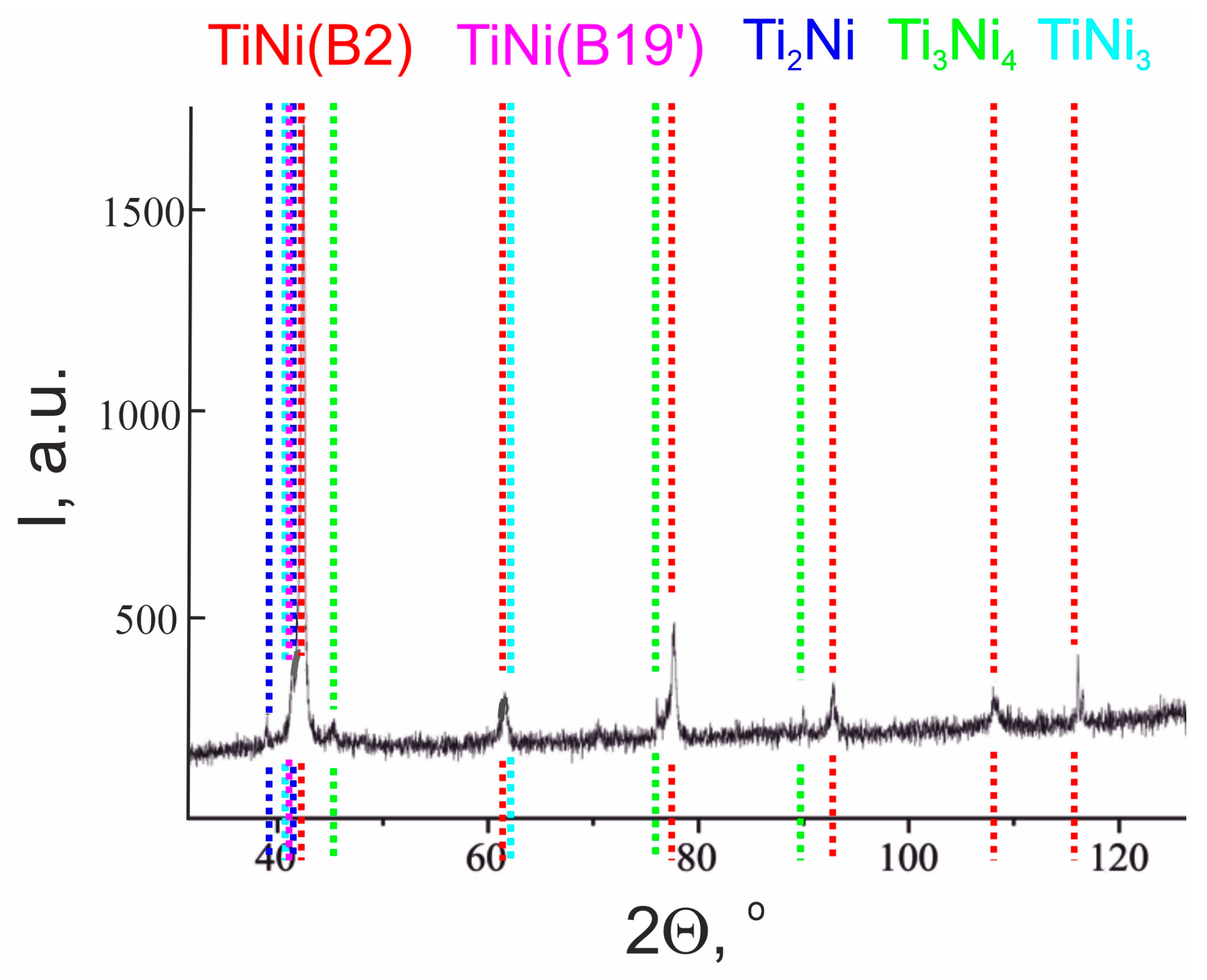
| Phase | Content, vol.% | Lattice Parameters, Å |
|---|---|---|
| TiNi (B2) | 71.9 | a = 3.0144 |
| TiNi (B19′) | 6.3 | a = 2.7826 |
| b = 4.6198 | ||
| c = 4.2130 | ||
| Ti2Ni | 12.0 | a = 11.3190 |
| TiNi3 | 4.3 | a = 5.0988 |
| c = 8.3347 | ||
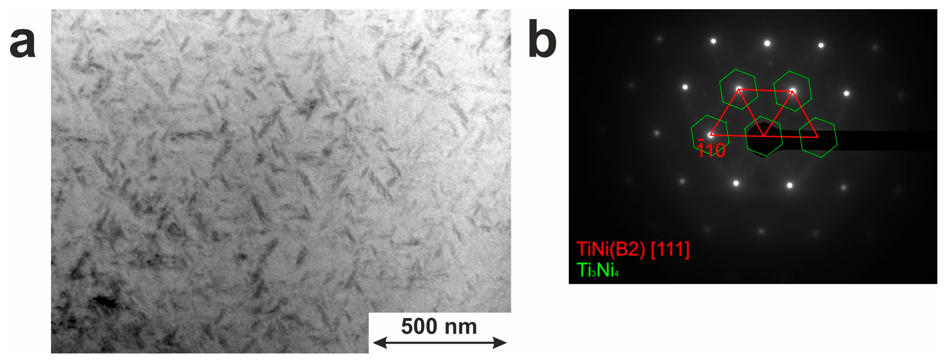
| Ti3Ni4 | 5.5 | a = 11.3137 |
| c = 5.0743 |
| Phase | Elemental Content *, at.% | |
|---|---|---|
| Ti | Ni | |
| TiNi (position 1) | 49.7 | 50.3 |
| Ti2Ni (position 2) | 66.03 | 33.97 |
| TiNi3 (position 3) | 26.83 | 73.17 |
| Cycle | Temperature, °C | ||||
|---|---|---|---|---|---|
| TR | Ms | Mf | As | Af | |
| 1 | 44 ± 2 | 24 ± 2 | 5 ± 2 | 32 ± 2 | 56 ± 2 |
| 2 | 38 ± 2 | 17 ± 2 | −2 ± 2 | 32 ± 2 | 56 ± 2 |
| 10 | 25 ± 2 | 0 ± 2 | −22 ± 2 | 33 ± 2 | 50 ± 2 |
| Temperature, °C | −196 | 0 | 25 | 150 | ||||
|---|---|---|---|---|---|---|---|---|
| , %/, MPa | ||||||||
| TiNi wire | 21 | 972 | 44 | 974 | 49 | 1013 | 36 | 810 |
| Index | Experimental Group (n = 18) | Control Group (n = 28) |
|---|---|---|
| Fatal cases | 1 (6%) | 15 (54%) |
| Stoma closure | 16 (89%) | 12 (43%) |
| No complications | 3 (17%) | 4 (14%) |
| Three or more complications | 7 (39%) | 9 (32%) |
| Peristomal dermatitis | 10 (56%) | 15 (54%) |
| Stoma prolapse | 4 (22%) | 9 (32%) |
| Bleeding | 4 (22%) | 6 (21%) |
| Hyperproduction of chyme | 11 (61%) | 11 (39%) |
| Liver failure | 2 (11%) | 6 (21%) |
| Stoma necrosis | 0 | 5 (18%) |
| Parastomal eventration | 2 (11%) | 2 (7%) |
| Intestinal obstruction | 2 (11%) | 10 (36%) |
Disclaimer/Publisher’s Note: The statements, opinions and data contained in all publications are solely those of the individual author(s) and contributor(s) and not of MDPI and/or the editor(s). MDPI and/or the editor(s) disclaim responsibility for any injury to people or property resulting from any ideas, methods, instructions or products referred to in the content. |
© 2023 by the authors. Licensee MDPI, Basel, Switzerland. This article is an open access article distributed under the terms and conditions of the Creative Commons Attribution (CC BY) license (https://creativecommons.org/licenses/by/4.0/).
Share and Cite
Anikeev, S.G.; Kaftaranova, M.I.; Hodorenko, V.N.; Ivanov, S.D.; Artyukhova, N.V.; Shabalina, A.V.; Kulinich, S.A.; Slizovsky, G.V.; Mokshin, A.V.; Gunther, V.E. TiNi-Based Material with Shape-Memory Effect for Surgical Treatment of Diseases of Small Intestine in Newborn and Young Children. J. Funct. Biomater. 2023, 14, 155. https://doi.org/10.3390/jfb14030155
Anikeev SG, Kaftaranova MI, Hodorenko VN, Ivanov SD, Artyukhova NV, Shabalina AV, Kulinich SA, Slizovsky GV, Mokshin AV, Gunther VE. TiNi-Based Material with Shape-Memory Effect for Surgical Treatment of Diseases of Small Intestine in Newborn and Young Children. Journal of Functional Biomaterials. 2023; 14(3):155. https://doi.org/10.3390/jfb14030155
Chicago/Turabian StyleAnikeev, Sergey G., Maria I. Kaftaranova, Valentina N. Hodorenko, Stanislav D. Ivanov, Nadezhda V. Artyukhova, Anastasiia V. Shabalina, Sergei A. Kulinich, Grigory V. Slizovsky, Anatolii V. Mokshin, and Victor E. Gunther. 2023. "TiNi-Based Material with Shape-Memory Effect for Surgical Treatment of Diseases of Small Intestine in Newborn and Young Children" Journal of Functional Biomaterials 14, no. 3: 155. https://doi.org/10.3390/jfb14030155