Article

Mathematical Modeling of Multi-Phase Filtration in a Deformable Porous Medium

Department of Mathematical Modeling, Faculty of Mathematics, Samarkand State University, University Blvd., Samarkand 140104, Uzbekistan
*
Author to whom correspondence should be addressed.
Computation 2023, 11(6), 112; https://doi.org/10.3390/computation11060112
Submission received: 8 May 2023 / Revised: 23 May 2023 / Accepted: 25 May 2023 / Published: 8 June 2023
(This article belongs to the Special Issue Computational Techniques for Fluid Dynamics Problems)

Abstract

:
In this paper, a mathematical model of multiphase filtration in a deformable porous medium is presented. Based on the proposed model, the influence of the deformation of a porous medium on the filtration processes is studied. Numerical calculations are performed and the characteristics of the process are determined. This paper shows that an increase in the compressibility coefficient leads to a sharp decrease in porosity, absolute permeability and internal pressure of the medium near the well, and a decrease in the distance between wells leads to a sharp decrease in hydrodynamic parameters in the inter-well zone.

1. Introduction

The study of the stress–strain state of a porous medium and pore pressure is motivated by the need to solve various applied problems in the mining and construction of structures [1]. Accounting for the redistribution of stresses and changes in pore pressure is important in oil and gas production, when the flow of the produced fluid to the well is ensured by pumping water into the formation [2]. In addition, the analysis of the stress–strain state of the foundation and the surrounding massif taking into account the flow of groundwater and possible flooding is an important link in the design of building structures [3].
Recent developments in mixture theory and applications of the theory in particular areas of biomechanics, composite manufacturing and infiltration into deformable porous materials are considered [4]. The complexity based upon different permeability and stress functions is also addressed.
The physics of such joint processes occurring in a fluid-saturated porous medium are complex and must simultaneously take into account that the change in the fluid pore pressure and the deformation of the solid skeleton of the porous medium through which the flow occurs [5]. The need to solve these practical problems motivated the development of mathematical models to describe such joint processes [3]. A mathematical model describing the mutual influence of a fluid flow and a change in the stress–strain state of a solid skeleton was first proposed in [6] to calculate the clay permeability coefficient. In this work, an effective stress tensor was introduced, which depends on the deformation of the skeleton and the fluid pressure. The basic equations of the mathematical model for describing the processes in a consolidated porous medium (the poroelasticity model) were formulated in [7,8]. In [7], the basic equations of the linear theory of poroelasticity were derived, which relates the stresses in the solid skeleton and the fluid pressure. A more general case of viscoelastic anisotropic porous bodies is given in [8]. Further studies were related to the propagation of elastic waves in a poroelastic medium saturated with liquid. Almost independently and at the same time, the fundamental equations for describing processes in saturated porous media were derived [9].
A nonlinear model of the flow of a mixture of compressible fluids in a porous medium was proposed using finite deformations and thermal effects. The model was developed in order to solve the problems arising in the study of hydrodynamic processes of different scales. The evolution of wave fields in inhomogeneous saturated porous media is considered [10]. The one-dimensional flow of a liquid through a deformable porous medium is studied theoretically and experimentally. The medium is considered that exerts the viscous resistance to a solid matrix, causing its deformation. A general theoretical model is derived, and the predictions of the model are in good agreement with experimental measurements [11].
Several studies have been presented on multiphase Thermo-Hydro-Mechanical (THM) models [12,13,14]. The first one [12] describes a model consisting of three phases: solid, liquid and gaseous, incorporating water–gas phase transitions. In this model, the deformations of the medium are described as elastoplastic, using the Barcelona Basic Model (BBM) for unsaturated soils. Another study focused on the investigation of nonisothermal three-phase filtration (solid phase–gas–water) considering elastic deformations of a porous medium [13]. The numerical solution of the model is based on the Galerkin method, and the results are validated using a series of tests on the permeability of MX-80 bentonite. The development of this model was further discussed in [14]. In this work, it was expanded by incorporating a more comprehensive set of phase relations. The deformations of the porous medium are described using the Biot model, with the inclusion of the thermal expansion coefficient.
A multiphase model was introduced to explain the filtration process of a chemically active liquid (brine) and a gas in saline [15]. This model considers the linear deformations of a porous medium and incorporates the chemical interaction between the solid and liquid phases. Building on the model presented in [16], a multiphase version was presented in [17]. The focus of [17] was on the injection of CO2, as part of the liquid phase, into a carbonate rock, accounting for the chemical interactions between the different phases. The numerical solution of this model follows a similar approach to the one described in [16].
Three primary approaches have been suggested to address the challenge posed by fluid flow in porous media that contain both solid-free regions and porous domains, commonly referred to as multiscale systems. One of the approaches involves conducting direct numerical simulations (DNSs) across the entire multiscale domain, including both within and outside the porous medium. Studies [18,19,20] have explored this technique. While this method is rigorous, it becomes impractical when dealing with significant differences in length scales between the largest and smallest pores. It necessitates extremely fine grids and substantial computational resources.
Two coupled methods were proposed for porous media containing miscible and immiscible fluids [21]. A new numerical method was presented to simulate the complicated process of two-phase fluid flow through deforming porous materials using a mesh-free technique, called the element-free Galerkin (EFG) method [22].
In the work [23], finite element modeling of fluid filtration in a deformable porous medium is considered. A transversally isotropic medium is taken as a deformable medium. The process of fluid filtration into horizontal wells in the direction of drift, which occurs in this transversely isotropic medium, has been studied. The behavior of saturated deformable porous media under compressive loading is studied using direct numerical simulation [24]. To perform numerical simulations, a parallel hybrid Boltzmann lattice and the finite element method are used. It is shown that the LBM-FEM method is an accurate and suitable method for further studies of porous media, especially inhomogeneous and anisotropic deformable porous media. For effective and convenient modeling of a real porous medium, a model of a bidisperse porous medium was used, which was created by reconstructing a digital image [25]. The thermohydromechanics model built on the basis of the Navier–Stokes equations and differential stress equations was solved using the finite element method.
Specific problems with initial and boundary values are described, which are intended for energy recovery methods. Computational issues of mass conservation and instability caused by convection, in particular, the displacement of a solid skeleton, are considered [26]. Two related models for a porous medium containing porous fluids are proposed (immiscible and miscible) in the study [21]. Particular attention is paid to the comparison between them at different stages of development and application. Each model has its own area of applicability and validity.
In [27] the possibilities of numerical simulation of nonisothermal multiphase multicomponent transfer in heterogeneous deformable porous materials is studied, and these are summarized. Particular attention was paid to the description of the mathematical formulation of the flow in deformable media and numerical methods for taking into account phase transitions. The computational properties of a new modification of the large particle method based on a nonlinear correction of artificial viscosity at the first (Eulerian) stage and hybridization of flows at the second (Lagrangian and final) stages, supplemented by a two-step Runge–Kutta algorithm in time, are studied. The method has a second-order approximation in space and time on smooth solutions. On the example of test problems of a supersonic gas flow in a channel with a step and double Mach reflection, the operability and computational efficiency of the method are confirmed in comparison with modern high-resolution schemes [28].
A numerical algorithm for calculating one- and two-dimensional processes of three-phase filtration is presented, based on the large particles method, using a through-counting scheme, which makes it possible to continuously calculate various filtration regions [29]. The stability of numerical schemes of the modified large particles method for nonstationary nonisothermal multiphase filtration is studied [30]. The stability criteria for the scheme of the modified large particles method as a whole are obtained.
In all the previous work, it has been mentioned that the approaches and algorithms for joint modeling of changes in the stress–strain state of a porous medium have systematic shortcomings. In the present work, the process of multiphase filtration in a deformable porous medium is modeled. In the mathematical model, we considered densities of the phases as constants and we neglected capillary pressures between the phases. In order to solve the problem, we used the large particles method. The influence of environmental deformation on filtration processes in the inter-well zone is investigated.

2. Materials and Methods

2.1. Formulation of the Problem

Consider an oil reservoir exposed by two production wells. We believe that the oil and water phases are involved in the filtration process in a deformable porous medium. It is also assumed that water and oil do not mix, do not exchange masses and do not change phases. In addition, it is assumed that the fluids in the reservoir are at a constant temperature and in a state of thermodynamic equilibrium, the capillary pressure jump between the phases is neglected and the pressures in the phases are equal.
The mathematical model of two-phase filtration in a deformable porous medium can be represented as follows:
The oil phase mass conservation equation is
t m ρ o s o + ρ o u o = 0
where s o is the saturation of the pore space with oil, ρ o is the density of the oil phase, m is the porosity and u o is the velocity of the oil phase.
The water phase mass conservation equation is
t m ρ w s w + ρ w u w = 0
where s w is the saturation of the pore space with water, ρ w is the density of the aqueous phase and u w is the velocity of the aqueous phase.
The phase filtering laws are taken in the form
u o = K k o μ o p , u w = K k w μ w p ,
where K , k o , k w are absolute and relative phase permeability coefficients, μ o is oil viscosity, μ w is water viscosity and p is pressure.
To clarify the law of porosity change, consider the stresses acting in a porous medium filled with liquid.
The mass of rocks located above the roof of the reservoir creates the so-called rock pressure p m , which can usually be considered unchanged during the development of the reservoir. Rock pressure is determined by the formula
p m = ρ m g H ,
where ρ m is the average density of rocks that make up the overlying layers and H is formation depth [31].
If we assume that the roof and bottom of the formation are absolutely impermeable and completely perceive the load of overlying rocks, then the rock pressure is balanced by the stress in the formation skeleton σ and the pressure p in the fluid, and in this case, the term proportional to g is neglected [32].
p m = 1 m σ + m p
Here, σ is the true stress in the skeleton of a porous medium, calculated per unit of horizontal area, mentally allocated at any point in the reservoir; it acts on parts of the area 1 m , and p is the pore pressure that acts on the rest of the area m [31]. It is more convenient to introduce the so-called effective stress σ e f f , defined as the difference between the stresses in the solid skeleton and the liquid phase and related to the true stress by the relation [32]
σ e f f = 1 m σ p .
From Equation (5), it follows that
p m = σ e f f + p .
The effective stress is physically interpreted as that part of the true stress σ in the solid phase, which is transmitted through the contact between grains of the skeleton, does not depend on the liquid and will also take place in a dry porous medium [33]. The concept of effective stress is also convenient because it can be determined from
σ e f f = Γ p
We can measure the load Γ , simulating rock pressure p m and pore pressure p [32,33].
Changes in porosity are due to both changes in pore pressure p and changes in effective stress σ e f f . When the pressure drops, the forces compressing each of the rock grains decrease, therefore the grain volume increases and the pore volume decreases. The increase in σ e f f leads to the fact that the grains of the rock experience additional deformation. That is, the contact surface between the grains increases and the packing of the grains is compacted; the grains can also be rearranged, the cementing agent and the grains themselves are destroyed and the grains are crushed, etc. [31].
In cases where p m = c o n s t , it is usually assumed that porosity depends only on pressure m = m p . Due to the small deformation of the solid phase, the change in porosity depends linearly on the change in pressure. Let us write down the rock compressibility law in terms of the reservoir elasticity coefficient β m [31] as
β m = d V p V d p
where d V p is the change in the pore volume in the formation element having a volume V when the pressure changes by d p . If the volume of the reservoir element is assumed to be constant, then d V p / V = d m and the rock compressibility law takes the form d m = β m d p or, in final form,
m = m 0 + β m p p 0
where m 0 is the porosity coefficient at p = p 0 [31].
With significant changes in pressure, the change in porosity is described by the equation
m = m 0 e β m p 0 p / m 0
It has been experimentally shown that not only porosity, but also permeability changes significantly with changes in reservoir pressure, and permeability often changes to a greater extent than porosity [31]. For small pressure changes, this dependence can be taken as linear, as
K = K 0 1 a K p 0 p ,
and at large pressure changes exponential dependence is used [31].
K = K 0 e a K p 0 p ,
where a K is the permeability coefficient and K 0 is the initial permeability.
Consider the equation for changing porosity in the form
m = m 0 + β m p p 0 ,
where β m is the reservoir elasticity coefficient.
To calculate the absolute permeability, we use the following empirical relationship [34]:
K = K 0 m m 0 n
Adding the appropriate equations of state, initial and boundary conditions, we obtain a closed system of equations. Since the bottomhole formation zone is symmetrical with respect to the well, in order to assess the qualitative picture of the processes occurring in it, it is possible to switch from a three-dimensional model to a one-dimensional one, taking into account the incompressibility of the phases. When ρ o = c o n s t and ρ w = c o n s t , then the system of Equations (1)–(15) can be represented as follows:
Oil phase mass conservation equation
t m s o + x u o = 0
Water phase mass conservation equation
t m s w + x u w = 0
Porosity change equation
m = m 0 + β m p p 0 ,
Phase filtration rate equations
u o = K k o μ o p x , u w = K k w μ w p x ,
Change in absolute permeability
K = K 0 m m 0 n .
Let us add to the system of equations the equality s o + s w = 1 and dependencies for viscosities μ o = c o n s t , μ w = c o n s t , and the relative phase permeability coefficients are
k o = 1 s w 1 s w E , s w > s w E , 1 s w s w E ;
k w = s w s w E 1 s w E , s w > s w E , 0 s w s w E ;
where s w E is the residual water saturation.
To derive an equation for pressure, we sum Equations (16) and (17). As a result, we obtain
t m s o + s w + x u o + u w = 0
Substituting s o + s w = 1 in Equation (23), we obtain
m t + x u o + u w = 0
Equation (24) is to be modified as
m t = t m 0 + β m p + p 0 = β m p t
In which m = m p and m = m 0 + β m p p 0 .
Finally, the pressure equation will take the form
β m p t = x K k 0 μ 0 + K k w μ w p x
The initial and boundary conditions are considered as follows:
p x , 0 = p 0 , s o x , 0 = s o 0 , s w x , 0 = s w 0
p 0 , t = p 0 , p l 1 , t = p 1 * , p l 2 , t = p 2 * , p L , t = p 0 , s o 0 , t = s o * , s w 0 , t = s w * , s o L , t = s o * * , s w L , t = s w * *
where l 1 is the coordinate of the first well, l 2 is the coordinate of the second well, L is the length of the filtration area, p 1 * is the pressure in the first well, p 2 * is the pressure in the second well, s o * is the oil saturation on the left boundary, s w * is the water saturation on the left boundary, s o * * is the oil saturation on the right boundary and s w * * is the oil saturation on the right boundary. Thus, we obtain a closed system of Equations (16)–(28) describing two-phase filtration in a deformable porous medium.

2.2. Method of Solution

Now, we need to solve the Equations (16)–(28) using the particle method [35].
We split the non-stationary system of Equations (16)–(28) into physical processes and in the region
Ω = x , t : 0 x L , 0 t τ .
we build the spatiotemporal Euler grid
Ω τ h = t j 1 = t j τ , j = 1 , T ¯ ; x i 1 = x i h , i = 1 , N ¯ .
The medium is modeled by a system of liquid particles coinciding at a given time with a cell of the Euler grid. We divide the calculation of each time step into two stages [35]:
Step 1. We neglect the effects associated with the movement of the elementary cell, and we approximate Equations (16)–(26) at the time
β m p i p i k τ = 1 h 2 K k 0 μ 0 + k w μ w i + 1 2 k p i + 1 K k 0 μ 0 + k w μ w i + 1 2 + K k 0 μ 0 + k w μ w i 1 2 k p i + K k 0 μ 0 + k w μ w i 1 2 k p i 1
A i p i 1 B i p i + C i p i + 1 = F i
where
A i = τ β m h 2 K k 0 μ 0 + k w μ w i 1 2 k
B i = 1 + τ β m h 2 K k 0 μ 0 + k w μ w i 1 2 k + K k 0 μ 0 + k w μ w i + 1 2 k
C i = τ β m h 2 K k 0 μ 0 + k w μ w i + 1 2 k       and       F i = p i k
We use the Thomas’ algorithm to solve the system of Equation (30). The coefficients of Thomas’ algorithm are calculated by the formulas
α i + 1 = C i B i A i α i , i = 1 , N ¯ β i + 1 = F i + A i β i B i A i α i , i = 1 , N ¯
and the pressure
p i = α i + 1 p i + 1 + β i + 1
From the boundary conditions, we have
α 1 = 0 , β 1 = p 0
p 0 , t = p 0 , p L , t = p 0
p l 1 , t = p 1 * , p l 2 , t = p 2 * .
Having determined the pressure values, we calculate the phase velocities
u o i + 1 2 = K k o μ o i p i p i + 1 h , u w i + 1 2 = K k w μ w i p i p i + 1 h
Step 2. Find the values of saturation, porosity and permeability
m i k + 1 = m 0 + β m p i p 0
s o i k + 1 = 1 m i k + 1 m i k + 1 s o i k + u o i 1 / 2 u o i + 1 / 2 h τ
s w i k + 1 = 1 s o i k + 1
k o i k + 1 = 1 s w i k + 1 1 s w E , s w i k + 1 > s w E 1 s w i k + 1 s w E
k w i k + 1 = s w i k + 1 s w E 1 s w E , s w i k + 1 > s w E 0 s w i k + 1 s w E ;
K i k + 1 = K 0 m i k + 1 m 0 n
Having received the values of the required parameters, we proceed to the next time layer, etc.

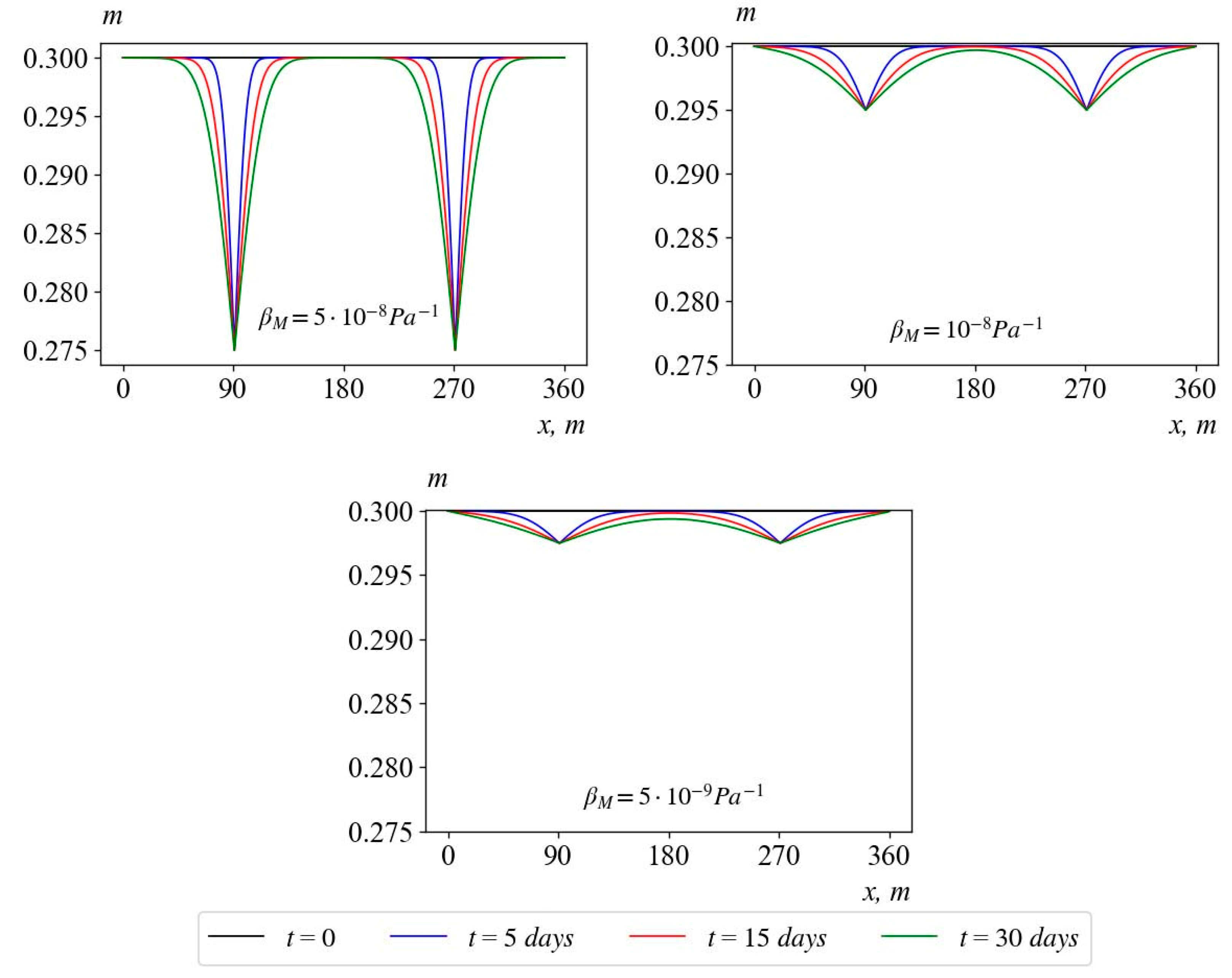
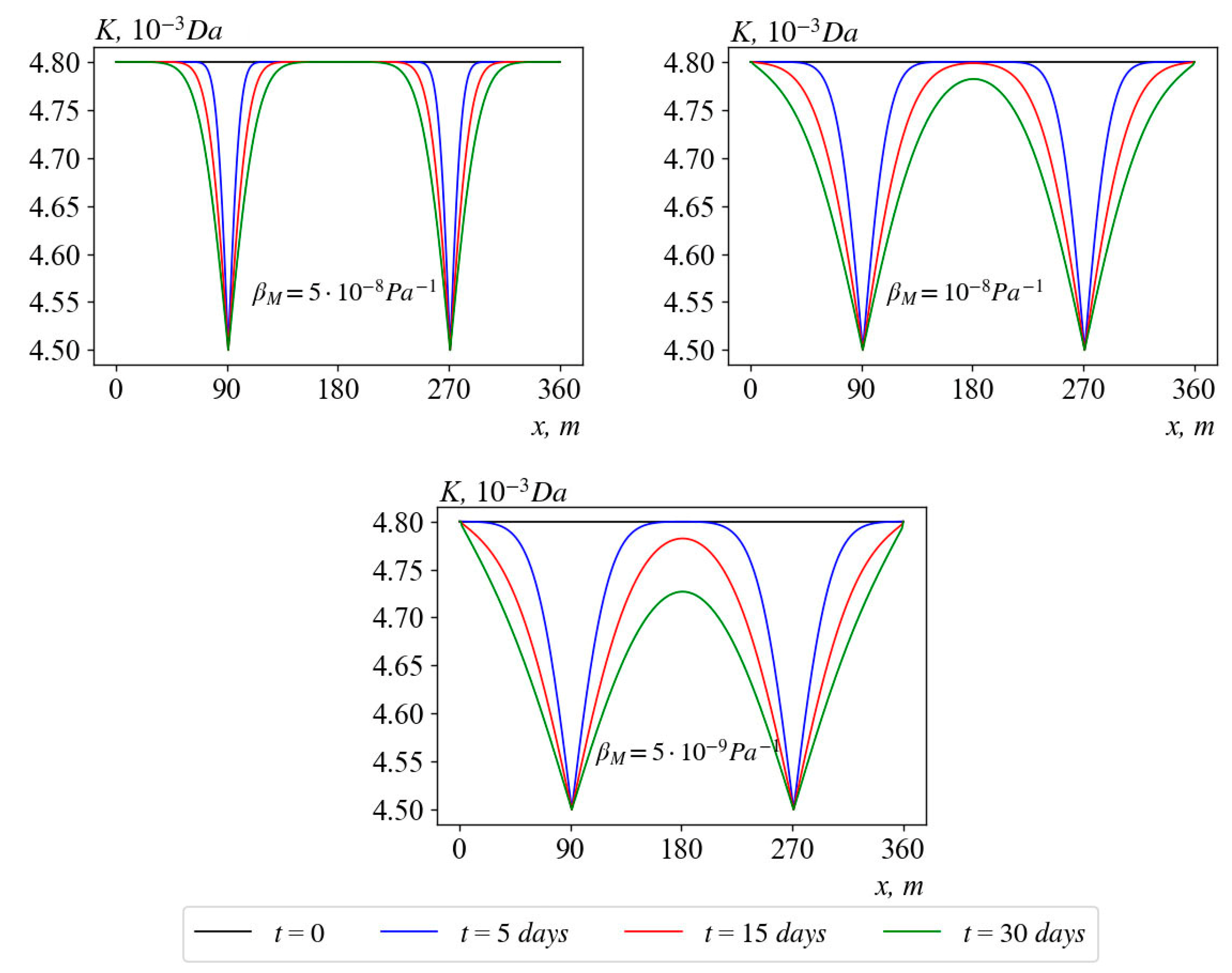
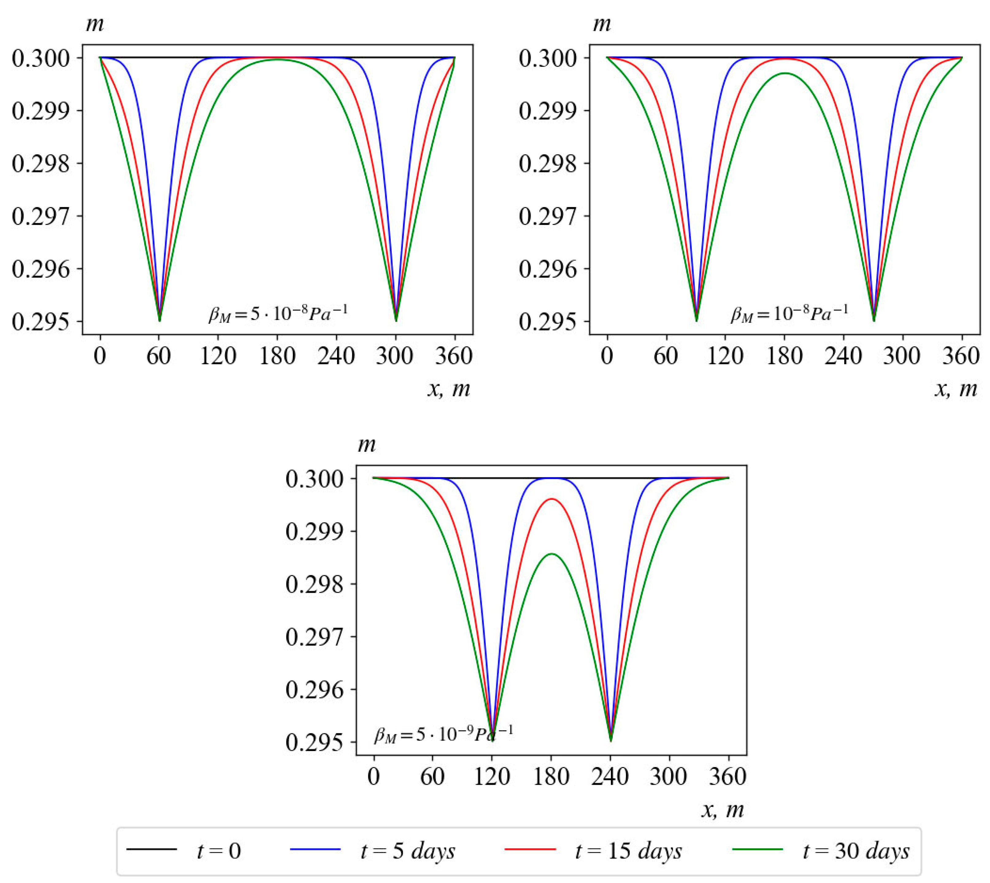
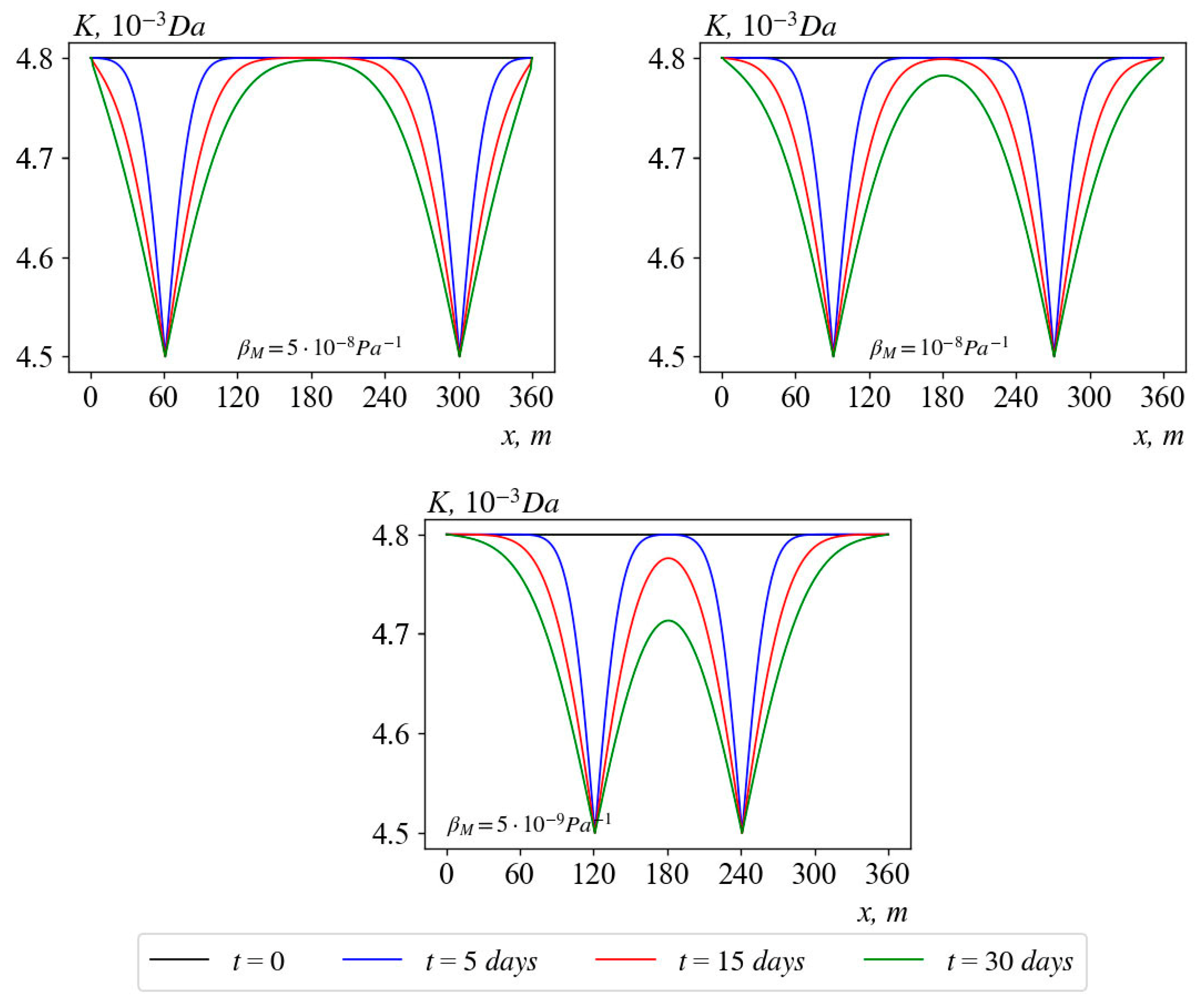
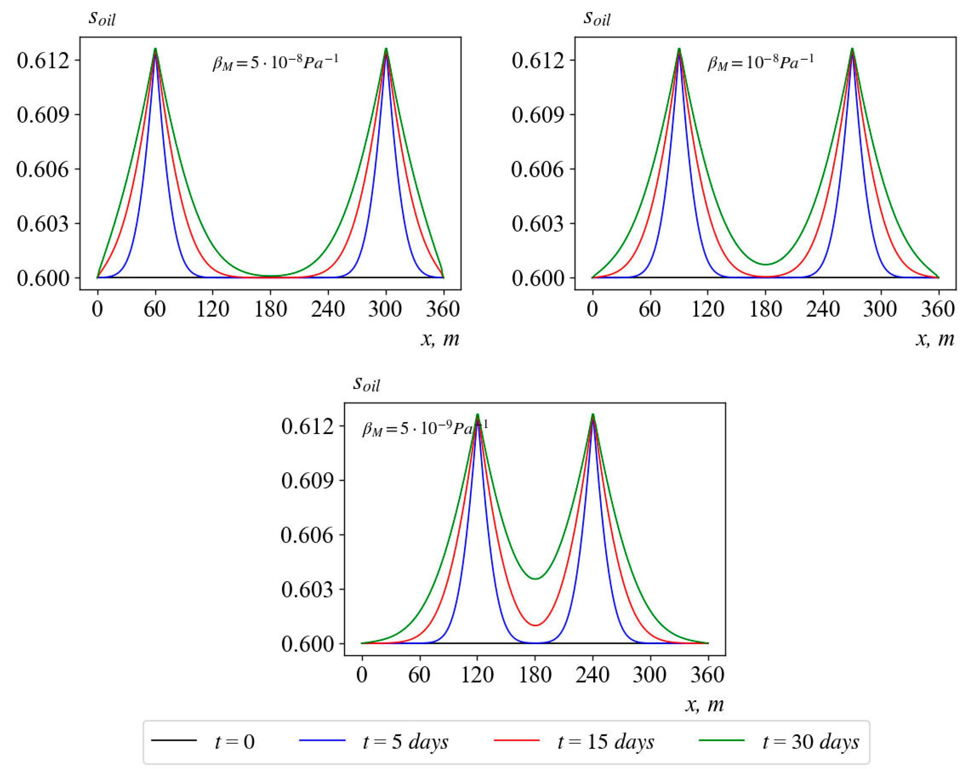
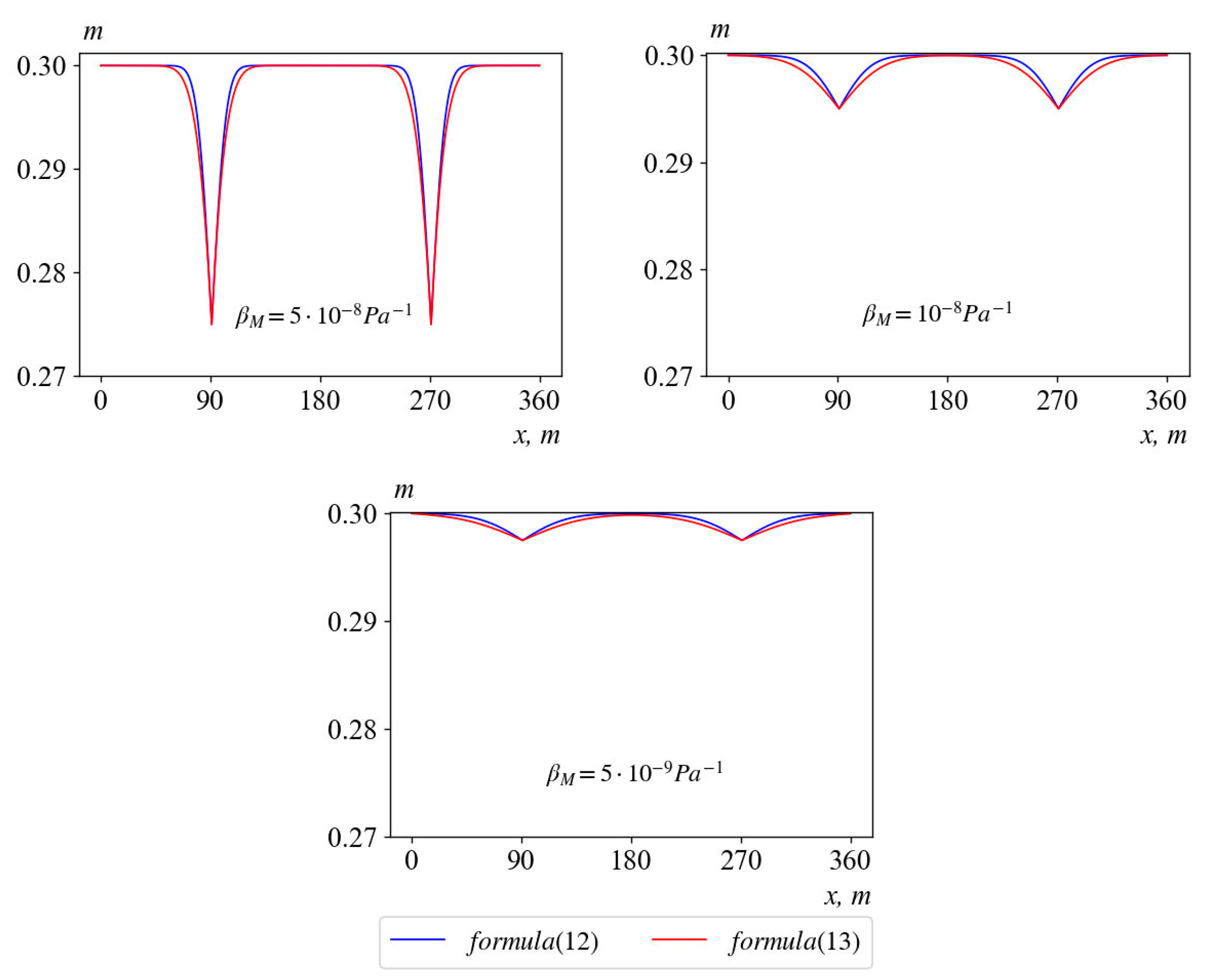
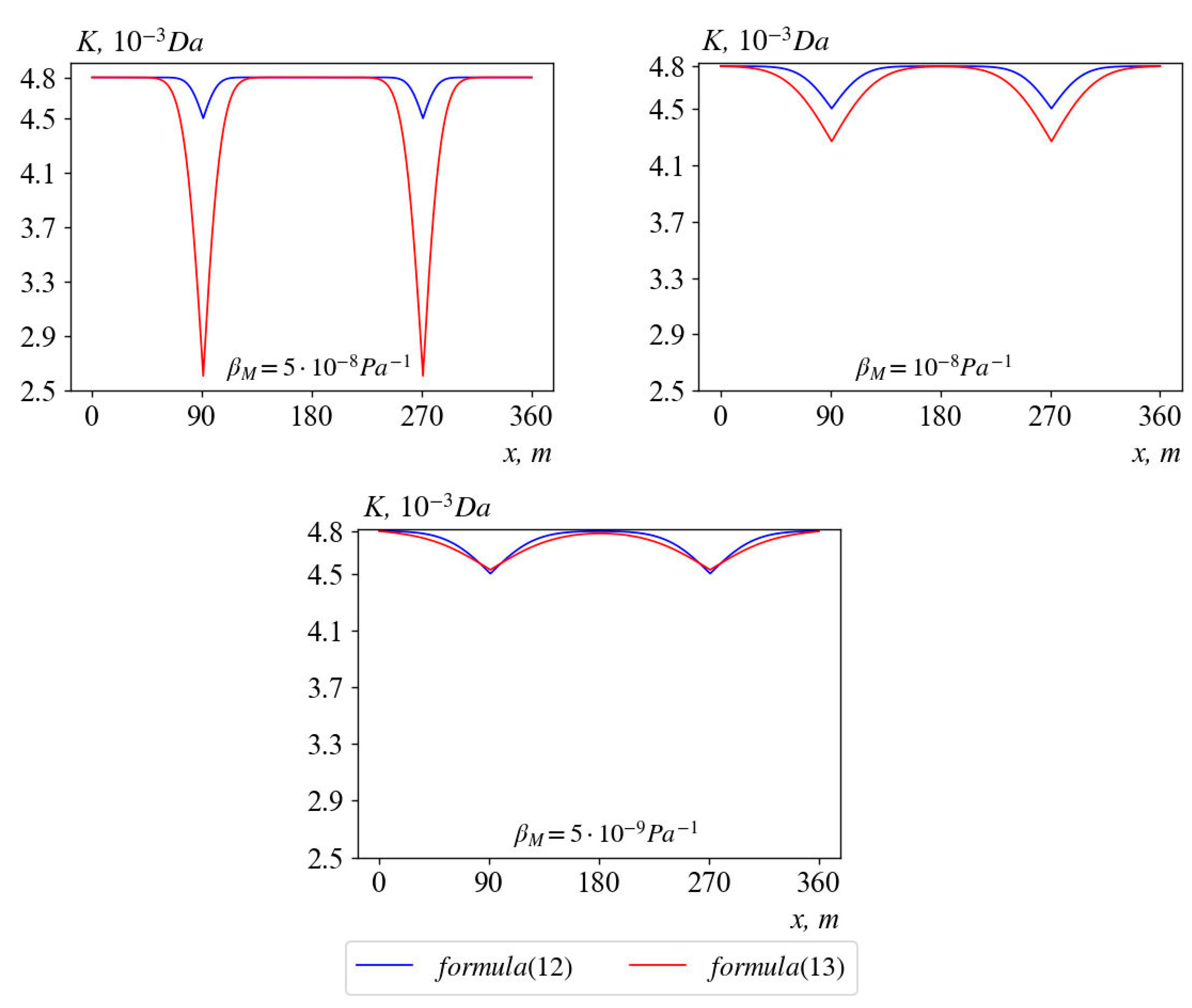
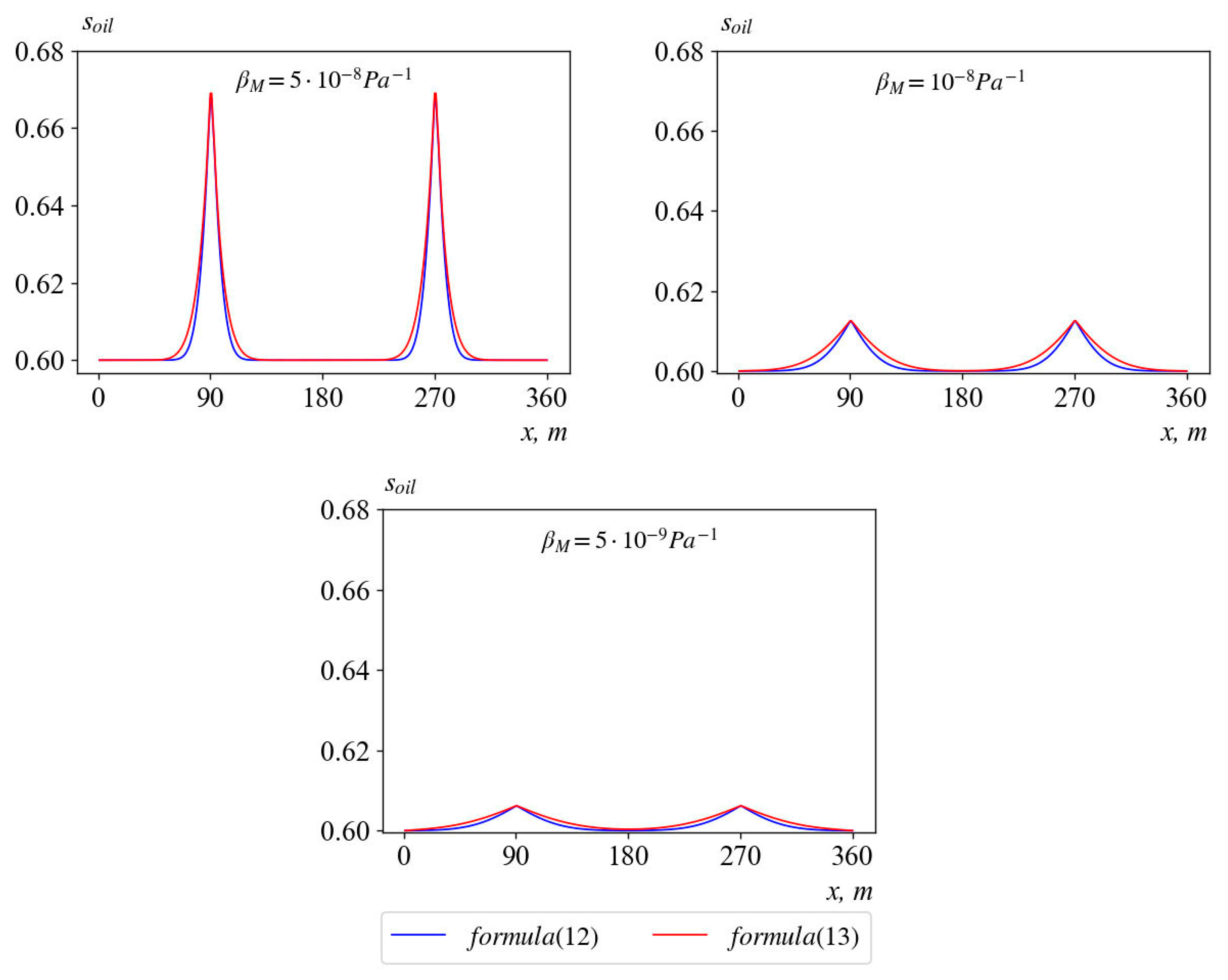
3. Results and Discussion

To study the stress–strain state of a saturated porous medium, computational procedures are carried out using the following parameter values: m 0 = 0.3 , K 0 = 4.8 10 15 m 2 , s w E = 0.1 , s o 0 = 0.6 , s w 0 = 0.4 , p 0 = 10 6 P a , p 0 = 10 6 Π a , p 1 * = 10 5 Π a , p 2 * = 10 5 Π a , s o * = 0.6 , s w * = 0.4 , s o * * = 0.6 , s w * * = 0.4 , μ o = 1.3 10 3 Π a c , μ w = 1.768 10 3 P a s , β m = 10 9 Π a 1 , l 1 = 90 m and l 2 = 270 m .
Figure 1 shows a graph of changes in the porosity of an oil reservoir for various values of the compressibility coefficient of the medium for t = 0, 5, 15 and 30. It can be seen from the graphs that with an increase in the value of the compressibility coefficient of the medium, a significant decrease in porosity is observed only in the bottomhole zone of the wells ( β m = 5 10 8 P a 1 ). In the rest of the formation, the effect of changing the compressibility coefficient of the medium is practically not felt.
Figure 2 depicts the changes in the permeability of an oil reservoir for various values of the medium compressibility factor. It can be seen from the graphs that an increase in the value of the compressibility coefficient of the medium has a significant impact on the permeability both in the bottom hole and in the rest of the formation. A particularly significant change is observed in the inter-well zone ( β m = 10 8 P a 1 and β m = 5 10 9 P a 1 ).
In Figure 3, the changes in the oil saturation of the medium at various values of the compressibility coefficient of the medium is studied. In these results, the increase in the value of the compressibility coefficient of the medium leads to a significant increase in oil saturation in the bottomhole zone of wells. At the same time, in the rest of the reservoir, it practically does not change.
Figure 4, Figure 5 and Figure 6 show the changes in porosity (Figure 4), permeability (Figure 5) and oil saturation (Figure 6) at different distances between the oil wells. It can be seen from the figures that at small distances between the wells ( β m = 10 8 P a 1 in Figure 4 and Figure 5), porosity and permeability in the inter-well zone changes more significantly than in the peripheral zones of the reservoir, which leads to an increase in oil saturation, especially in the inter-well zone ( β m = 10 8 P a 1 and β m = 5 10 9 P a 1 in Figure 6).
Figure 7, Figure 8 and Figure 9 compare the changes in porosity, permeability and oil saturation at different values of the reservoir compressibility factor in cases where the relations (12) and (15) are used to determine the permeability of an oil reservoir. Thus, the result shows that when using both ratios, porosity and oil saturation (Figure 7 and Figure 9) practically coincide, and permeability (Figure 8) increases with an increase in the compressibility factor, then there is a significant decrease in the zone of propagation of changes in the reservoir.

4. Conclusions

This paper considered the problem of mathematical modeling of the process of two-phase filtration in a deformable porous medium. In this paper, density of oil and water are considered constant and capillary pressure is neglected. To solve this problem, the method of large particles is used. The results of the study show that with an increase in the compressibility coefficient of the medium, the porosity, absolute permeability and internal pressure of the medium near the well are sharply reduced, and the uneven change in porosity leads to the formation of an S-structure of the saturation distribution. At the same time, with a decrease in the distance between the wells in the inter-well zone, a sharp decrease in the studied parameters is observed. Therefore, it is necessary to take into account their influence on each other when drilling wells. To determine the absolute permeability, the influence of various dependencies on hydrodynamic parameters are studied, and a significant change in the absolute permeability profile is observed compared to the profiles of other hydrodynamic parameters. The results obtained are easily generalized to the real situation of a heterogeneous reservoir.
The resulting one-dimensional model, taking into account the assumptions made, can be used to describe the processes occurring in the inter-well oil reservoir. Further development of the model is associated with the determination of the volumetric elasticity coefficient of the reservoir obtained in laboratory experiments and refinement of the description of the filtration process in a deformable porous medium, taking into account multidimensionality.

Author Contributions

Conceptualization, Z.D.K. and V.F.B.; methodology, V.F.B.; software, Z.D.K.; validation, Z.D.K. and K.K.V.; formal analysis, V.F.B.; investigation, Z.D.K.; resources, V.F.B. and K.K.V.; data curation, Z.D.K.; writing—original draft preparation, Z.D.K.; writing—review and editing, K.K.V. and V.F.B.; visualization, Z.D.K.; supervision, V.F.B. All authors have read and agreed to the published version of the manuscript.

Funding

This research received no external funding.

Institutional Review Board Statement

Not Applicable.

Informed Consent Statement

Not Applicable.

Data Availability Statement

Not Applicable.

Conflicts of Interest

The authors declare no conflict of interest.

References

  1. Bohnsack, D.; Potten, M.; Freitag, S.; Einsiedl, F.; Zosseder, K. Stress sensitivity of porosity and permeability under varying hydrostatic stress conditions for different carbonate rock types of the geothermal Malm reservoir in Southern Germany. Geotherm. Energy 2021, 9, 59. [Google Scholar] [CrossRef]
  2. Channa, Z.; Khan, M.N.; Iwama, H.; Husain, A.; Al-blooshi, J.R.; El-Sayed, H.S.; Nofal, S.F.; Al-feky, M.H.; Fazeel, A. The Performance of Water Injection Wells Equipped with ICD Completions in One of the Giant Offshore Field, Abu Dhabi; Society of Petroleum Engineers: Abu Dhabi, United Arab Emirates, 2016. [Google Scholar] [CrossRef]
  3. Burnashev, V.F.; Kaytarov, Z.D. Mathematical modeling of multiphase filtration taking into account the deformation of a porous medium. Probl. Comput. Appl. Math. 2022, 3, 5–20. [Google Scholar]
  4. Siddique, J.I.; Ahmed, A.; Aziz, A.; Khalique, C.M. A Review of Mixture Theory for Deformable Porous Media and Applications. Appl. Sci. 2017, 7, 917. [Google Scholar] [CrossRef] [Green Version]
  5. Bui, H.H.; Giang, D.N. A coupled fluid-solid SPH approach to modeling flow through deformable porous media. Int. J. Solids Struct. 2017, 125, 244–265. [Google Scholar] [CrossRef]
  6. Terzaghi, K. The shearing resistance of saturated soils. In Proceedings of the International Conference on Soil Mechanics and Foundation Engineering, Cambridge, MA, USA, 22–26 June 1936. [Google Scholar]
  7. Biot, M.A. General Theory of Three Dimensional Consolidation. J. Appl. Phys. 1941, 12, 155–161. [Google Scholar] [CrossRef]
  8. Biot, M.A. Theory of Elasticity and Consolidation for a Porous Anisotropic Solid. J. Appl. Phys. 1955, 26, 182–185. [Google Scholar] [CrossRef]
  9. Frenkel, Y.I. On the theory of seismic and seismo-electric phenomena in wet soil. Geogr. Geophys. 1944, 4, 133–150. [Google Scholar]
  10. Perepechko, L.; Romenski, E.; Reshetova, G.; Kireev, S.; Perepechko, Y. Modeling the multiphase flows in deformable porous media. MATEC Web Conf. 2017, 115, 4. [Google Scholar] [CrossRef] [Green Version]
  11. Hewitt, D.R.; Nijjer, J.S.; Worster, M.G.; Neufeld, J.A. Flow-induced compaction of a deformable porous medium. Phys. Rev. E 2016, 93, 023116. [Google Scholar] [CrossRef] [Green Version]
  12. Abed, A.A.; Sołowski, W.T. A study on how to couple thermo-hydro-mechanical behavior of unsaturated soils: Physical equations, numerical implementation and examples. Comput. Geotech. 2017, 92, 132–155. [Google Scholar] [CrossRef]
  13. Chen, Y.; Zhou, C.; Jing, L. Modeling coupled THM processes of geological porous media with multiphase flow: Theory and validation against laboratory and field scale experiments. Comput. Geotech. 2009, 36, 1308–1329. [Google Scholar] [CrossRef]
  14. Tong, F.; Jing, L.; Zimmerman, R.W. A fully coupled thermo-hydro-mechanical model for simulating multiphase flow, deformation and heat transfer in buffer material and rock masses. Int. J. Rock Mech. Min. Sci 2010, 47, 205–217. [Google Scholar] [CrossRef]
  15. Olivella, S.; Carrera, J.; Gens, A.; Alonso, E.E. Nonisothermal multiphase flow of brine and gas through saline media. Transp. Porous Media 1994, 15, 271–293. [Google Scholar] [CrossRef]
  16. Yin, S.; Towler, B.F.; Rothenburg, L. Fully coupled THMC modeling of wellbore stability with thermal and solute convection considered. Transp. Porous Media 2010, 84, 773–798. [Google Scholar] [CrossRef]
  17. Yin, S.; Dusseault, M.B.; Rothenburg, L. Coupled THMC modeling of CO2 injection by finite element methods. J. Pet. Sci. Eng 2011, 80, 53–60. [Google Scholar] [CrossRef]
  18. Breugem, W.P.; Boersma, B.J. Direct numerical simulations of turbulent flow over a permeable wall using a direct and a continuum approach. Phys. Fluids 2005, 17, 1–15. [Google Scholar] [CrossRef]
  19. Hahn, S.; Je, J.; Choi, H. Direct numerical simulation of turbulent channel flow with permeable walls. J. Fluid Mech. 2002, 450, 259–285. [Google Scholar] [CrossRef]
  20. Krafczyk, M.; Kucher, K.; Wang, Y.; Geier, M. DNS/LES Studies of Turbulent Flows Based on the Cumulant Lattice Boltzmann Approach. High Perform. Comput. Sci. Eng. 2014, 14, 519–531. [Google Scholar] [CrossRef]
  21. Klubertanz, G.; Bouchelaghem, F.; Laloui, L.; Vulliet, L. Miscible and Immiscible Multiphase Flow in Deformable Porous Media. Math. Comput. Model. 2003, 37, 571–582. [Google Scholar] [CrossRef]
  22. Soodeh, S.; Ali, P. A three-dimensional mesh-free model for analyzing multi-phase flow in deforming porous media. Meccanica 2015, 51, 517–536. [Google Scholar] [CrossRef]
  23. Azhikhanov, N.T.; Zhumagulov, B.T.; Masanov, Z.K.; Bekbolatov, A.B. Finite element modeling of fluid filtration in a deformable porous medium. J. Phys. Conf. Ser. 2019, 1425, 012137. [Google Scholar] [CrossRef]
  24. Khan, I. Direct Numerical Simulation and Analysis of Saturated Deformable Porous Media. Ph.D. Thesis, Georgia Institute of Technology, North Ave NW, Atlanta, GA, USA, 5 July 2010. [Google Scholar]
  25. Mou, X.; Chen, Z. Pore-scale simulation of heat and mass transfer in deformable porous media. Int. J. Heat Mass Transf. 2020, 158, 10. [Google Scholar] [CrossRef]
  26. Loret, B. Computational Issues in Deformable Porous Media. In Fluid Injection in Deformable Geological Formations, 1st ed.; Springer International Publishing: New York, NY, USA, 2019; pp. 145–248. [Google Scholar]
  27. Class, H.; Helmig, R. Numerical simulation of non-isothermal multiphase multicomponent processes in porous media.: 2. Applications for the injection of steam and air. Adv. Water Resour. 2002, 25, 551–564. [Google Scholar] [CrossRef]
  28. Sadin, D.V.; Belyaev, B.V.; Davidchuk, V.A. Comparison of the modified coarse particle method with some high resolution schemes. two-dimensional tests. Calc. Methods Program. 2019, 20, 337–345. [Google Scholar]
  29. Abutaliev, F.B.; Burnashev, V.F. Modified method of “large particles” for non-stationary non-isothermal multi-phase multi-component filtration with phase transitions. Doc. AN RUz 1991, 12, 22–25. [Google Scholar]
  30. Abutaliev, F.B.; Burnashev, V.F. Investigation of the stability of numerical schemes of the large particle method for non-stationary non-isothermal multiphase filtration. Doc. AN RUz 1997, 1, 19–25. [Google Scholar]
  31. Basniev, K.S.; Kochina, I.N.; Maksimov, V.M. Underground Hydromechanics, 1st ed.; Nedra: Moscow, Russia, 1993; p. 416. [Google Scholar]
  32. Vincenzo, G. 1923–2023: One Century since Formulation of the Effective Stress Principle, the Consolidation Theory and Fluid-Porous-Solid Interaction Models. Geotechnics 2022, 2, 961–988. [Google Scholar]
  33. Guerriero, V.; Mazzoli, S. Theory of Effective Stress in Soil and Rock and Implications for Fracturing Processes. A Review. Geosciences 2021, 11, 119. [Google Scholar] [CrossRef]
  34. Bulgakova, G.T.; Baizigitova, A.V.; Sharifullin, A.R. Model of matrix acid treatment of carbonates: Influence of sediment on the dissolution process. Ufa UG ATU 2009, 2, 256–264. [Google Scholar]
  35. Belotserkovsky, O.M.; Davydov, Y.M. Method of Large Particles in Gas Dynamics, 1st ed.; Nauka: Moscow, Russia, 1982; p. 392. [Google Scholar]
Figure 1. Effect of medium deformation on porosity.
Computation 11 00112 g001
Figure 2. Effect of medium deformation on absolute permeability.
Computation 11 00112 g002
Figure 3. Effect of medium deformation on oil saturation.
Computation 11 00112 g003
Figure 4. Change in reservoir porosity at different distances between the wells.
Computation 11 00112 g004
Figure 5. Change in reservoir permeability at different distances between the wells.
Computation 11 00112 g005
Figure 6. Change in reservoir oil saturation at different distances between wells.
Computation 11 00112 g006
Figure 7. Change in reservoir porosity with different analytical dependencies used to determine absolute permeability.
Computation 11 00112 g007
Figure 8. Change in reservoir permeability obtained with various analytical dependencies used to determine the absolute permeability.
Computation 11 00112 g008
Figure 9. The change in the oil saturation of the reservoir obtained with various analytical dependencies used to determine the absolute permeability.
Computation 11 00112 g009
Disclaimer/Publisher’s Note: The statements, opinions and data contained in all publications are solely those of the individual author(s) and contributor(s) and not of MDPI and/or the editor(s). MDPI and/or the editor(s) disclaim responsibility for any injury to people or property resulting from any ideas, methods, instructions or products referred to in the content.

