1. Introduction
In traditional common building design, full guidelines and instructions are provided for the earthquake resistance of buildings constructed with reinforced concrete (r/c) or steel according to the applicable regulations, such as Eurocode 8 (EC8) [
1], Eurocode 2 (EC2) [
2] and Eurocode 3 (EC3) [
3]. At the same time, relevant literature and numerous research works are available worldwide regarding the construction of a whole building with the same material. However, examples of various buildings can be found where the steel story/ies are constructed upon existing r/c structures due to various reasons such as renovation works, change of building use or a structural upgrade. The resulting hybrid r/c–steel building benefits from the advantages and disadvantages of the different structural materials, as indicated by Maley et al. [
4]. The consideration of added steel stories as a secondary structure, involving an essentially smaller secondary structure attached to the primary one, has been examined by Villaverde [
5] and Lu et al. [
6]. Nevertheless, the present work investigates the structural case of upper structural steel stories supported on existing r/c ones, with the same size in plan and a similar story height, therefore adding a significant mass and weight to the existing structure. This hybrid construction type, using different building materials in a vertical dimension, is not covered by the current regulations, EC8 [
1], EC2 [
2] and EC3 [
3], raising scientific interest due to its frequent occurrence in common practice.
So far, limited research with a similar subject to the current study is available in the worldwide literature. An investigation of the behavior of vertically mixed frames has been accomplished [
7] by “non-linear time-history” (NLTH) analysis for strong earthquakes, where all stories, constructed either from reinforced concrete or steel, were designed according to the current seismic code EC8 [
1]. An estimation of the seismic fragility of tall multi-story mixed buildings was performed by Kiani et al. [
8]. A mixed concrete–steel five-story frame was analyzed by Pnevmatikos et al. [
9] through NLTH analysis for three damage states. Fanaie and Shamlou [
10] analyzed multi-story mixed structures using various methods of analysis in 2D conditions for 15 earthquakes. Qian et al. [
11] investigated vertically mixed 2D steel–concrete structures.
Conforming to effective regulations, such as [
1], [
2] and [
3], the damping ratio is defined as 5% for reinforced concrete common frames, and 2% for steel ones, while a single value is not provided for hybrid frames. There are few research papers in the literature involving a uniform damping ratio available for the analysis of vertically mixed structures, as mentioned by Papageorgiou and Gantes [
12,
13] and Lu et al. [
6]. The use of one damping ratio for the mixed frame can save time in the time-consuming NLTH analysis, avoiding the use of several ratio values and consequently reducing the number of analyses, as mentioned by Farghaly [
14]. Sivandi-Pour et al. [
15,
16] presented a numerical method for the estimation of one value of the damping ratio for mixed structures. An arithmetic evaluation of the damping ratio of some mixed building models was described by Kaveh and Ardebili [
17] while considering soil–structure interaction.
In addition, a lack of modern seismic codes that recognize the influence of multiple ground excitations on structural behavior has been identified in various research studies. Hatzivassiliou and Hatzigeorgiou [
18] investigated the effects of sequential earthquakes on 3D r/c buildings, while Hatzigeorgiou and Liolios [
19] similarly dealt with 2D r/c frames. Hatzigeorgiou and Beskos [
20] and Hatzigeorgiou [
21,
22] used the simple one-degree-of-freedom model in examining multiple earthquakes. Zhang et al. [
23] and Yang et al. [
24] studied more complex non-linear structures in near-fault repeated earthquakes.
Additionally, various research works have noticed the effect of the excitation direction on the resulting response, mainly with an inflexible base assumption as in Ning et al. [
25], Bugueño et al. [
26], Athanatopoulou [
27] and Altunişik and Kalkan [
28]; and also considering the influence of a flexible base, as in the research by Askouni and Karabalis [
29,
30] and Katsimpini et al. [
31]. In later works [
25,
26,
27,
28,
29,
30,
31], efforts have been carried out to identify the crucial direction of the excitation judging from the most unfavorable response characteristics.
As observed in the aforementioned literature, hybrid building types are usually assessed in the same way as recently constructed buildings dimensioned according to the current seismic codes, EC8 [
1], since no better alternative guideline is available. However, here, an attempt is undertaken to investigate the behavior of hybrid frames consisting of a reinforced concrete part corresponding to an existing older structure and a steel part corresponding to a new one. The focus in this paper is on the dynamic behavior of the whole r/c–steel building system, more specifically involving hybrid buildings consisting of an r/c part governed by older seismic codes and a steel part by recent code provisions, by a simple approximation as explained in the following section. The ground excitation considered is of the sequential type, although this study does not attempt to solely focus on the effects of multiple ground excitations compared to single events, which is already investigated in the literature, e.g., [
18,
19,
20,
21,
22]. In addition, the effect of the earthquake direction is explored in the current elastoplastic dynamic analyses, as this has been shown to possibly affect the seismic structural behavior in various research works, including [
7,
25,
26,
27,
28,
29,
30,
31]. The consideration of the elastoplastic performance of reinforced concrete or steel structural members is simply incorporated in the analysis model, without interfering with more detailed mechanical models available in the literature on the respective mechanical characteristics of r/c and steel cross-sections, which do not belong to the current study’s focus.
The accomplished NLTH analyses aim to perform a numerical evaluation of the behavior of the aforementioned hybrid r/c–steel framed building type under selected sequential earthquakes, by using dimensionless global parameters, as described in the following sections.
2. Description of Hybrid Frames and Analysis Assumptions
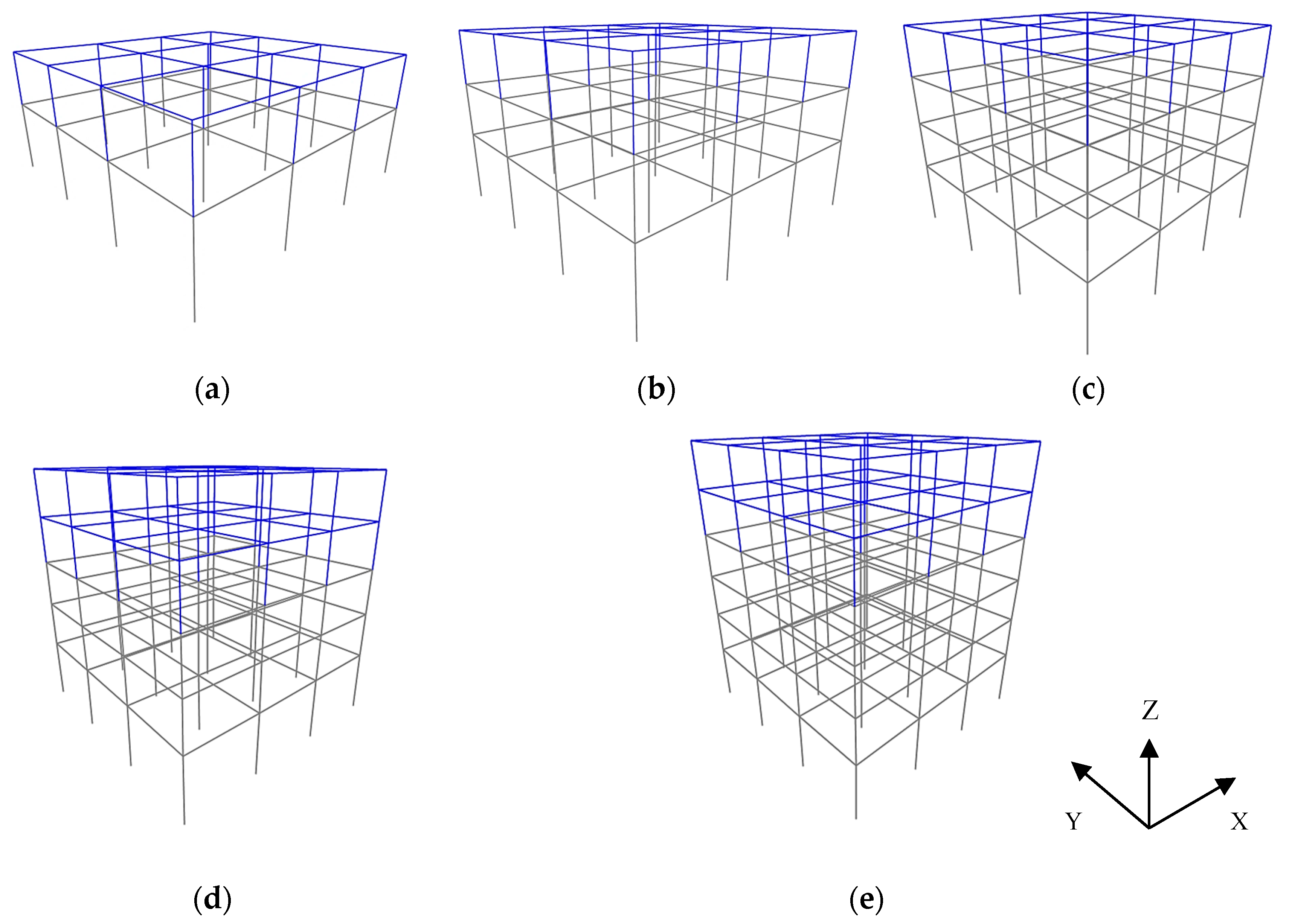
The two-, three-, four-, five- and six-story 3D hybrid building frames under investigation are shown in
Figure 1, where the presented analysis models are constructed by the SAP2000 software version 19.0 [
32]. The lower story/ies of these 3D building frames in
Figure 1, shown in grey color, are considered to be made of reinforced concrete, while the higher story/ies, shown in blue color, by structural steel. These building frames have a square floor plan of 15.0 × 15.0 m
2 consisting of three equal spans with a width of 5.0 m.
The height of the bottom story of the hybrid buildings is 4.0 m while the height of the upper story/ies is 3.0 m. On each floor of the hybrid frames, rigid reinforced concrete or composite slabs, 0.15 m thick, are designed. The material of the reinforced concrete story/ies is concrete C20/25 reinforced with steel S500 referring to former r/c construction. The steel story/ies consist of columns with steel grade S355 and beams with steel grade S275 referring to recent construction. The slab loads are 5.0 kN/m
2 uniformly applied as a permanent load and 0.6 kN/m
2 as a moving load, following Eurocode 1 (EC1) [
33]. On the edge beams, a dead load of external walls is applied equal to 3.6 kN/m
2 per wall height. The hybrid buildings are seismically designed as common domestic ones complying with the codes, EC1 [
1] and the Greek Anti-seismic Regulation (EAK) [
34]. The steel part of the hybrid frames is designed for a zone ground acceleration of 0.24 g corresponding to recent building structures for a ductility class medium (DCM), behaving as moment resisting frames (MRF) in both horizontal directions with a behavior factor equal to 4.0 according to EC8 [
1] and EC3 [
3]. The seismic design assumptions are: type 1 spectrum, 5% viscous damping ratio and C ground, 1.0 importance factor according to EC8 [
1]. The reinforced concrete stories are designed for a zone ground acceleration of 0.16 g and a behavior factor equal to 3.5, according to EAK [
34], and are detailed as former structures following the provisions of the Greek Code for R/C Design [
35]. As is widely known, the usual practice of adding stories to an existing structure induces the need to re-assess the strength of the existing stories. However, the current study does not intend to cover the subject of reassessing or rehabilitation of existing structures. From this viewpoint, the cross-sections of reinforced concrete members are selected through an initial dimensioning of an equivalent r/c structure with the same number of stories for each one of the hybrid buildings, by considering the higher ground acceleration of the steel part, i.e., 0.24 g. By using this simple approximation, the minimum necessary strength of the reinforced concrete part of the hybrid frame is assured, while issues of strength evaluation, or even possibly strengthening the r/c stories are deliberately avoided. In this way, the focus of this study remains on the investigation of the behavior of the entire hybrid frames.
The ground flexibility effect is neglected in the current investigation, assumed as small for ordinary buildings. Consequently, the hybrid buildings are designed considering the rigid soil assumption following EC8 [
1] and EAK [
34]. The seismic loading is considered in both horizontal directions following the 30% combination rule of EC8 [
1], and an accidental eccentricity of 5% [
1]. The detailing of the hybrid frames is carried out separately for the reinforced concrete part and the steel one, following the previously mentioned assumptions. The final design check is performed for the displacement limit of EC8 [
1] considering “brittle non-structural elements” [
1]. The final detailing and dimensioning of structural elements of the hybrid building frames (
Figure 1) are shown in
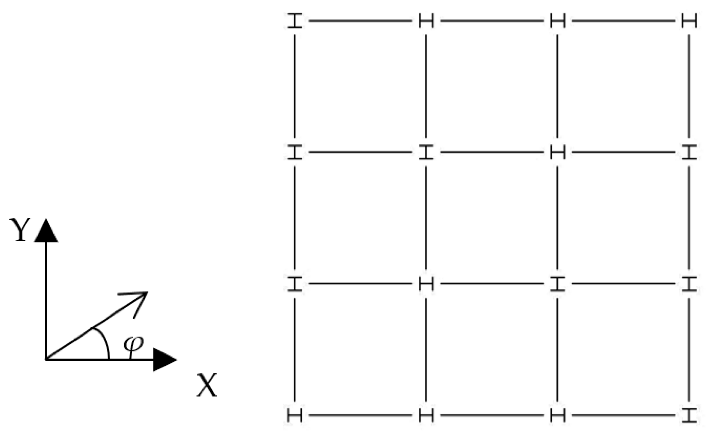
Table 1. The square cross-section of r/c columns is chosen to be the same in each story, for simplicity reasons. The steel columns in each story are oriented to preserve a strong perimeter, as shown in
Figure 2, which was designed by [
32,
36].
The upper steel part is connected to the lower r/c part by the two examples considered: a fixed connection of the steel columns, (moment carrying) in both horizontal directions of the hybrid frame, called “rigid” here; a fixed connection of the steel columns in one horizontal axis, i.e., the minor axis of each vertical element cross-section, and a nominally pinned connection in the other horizontal axis, i.e., the major axis of each vertical element cross-section, indicating that they are carrying small/no moment, called “semi-pinned” here. This distinction examines the two boundary supporting conditions of the steel part connected to the reinforced concrete one. In these hybrid reinforced concrete–steel buildings, the dimensioning and detailing of the structural elements are those shown in
Table 1, for comparison purposes between the two previous connection types of the steel story/ies upon the r/c ones.
The modal analysis of the hybrid reinforced frames is performed for the previous two supporting examples. In
Table 2, the modal period and participating mass ratios for the first three significant modes are presented for each hybrid frame, as obtained by the results of the modal analysis of these frames which was carried out by [
32].
3. Seismic Excitation and Analysis Issues
The non-linear dynamic investigation of the 3D hybrid frames is accomplished by the finite element software SAP2000 version 19.0 [
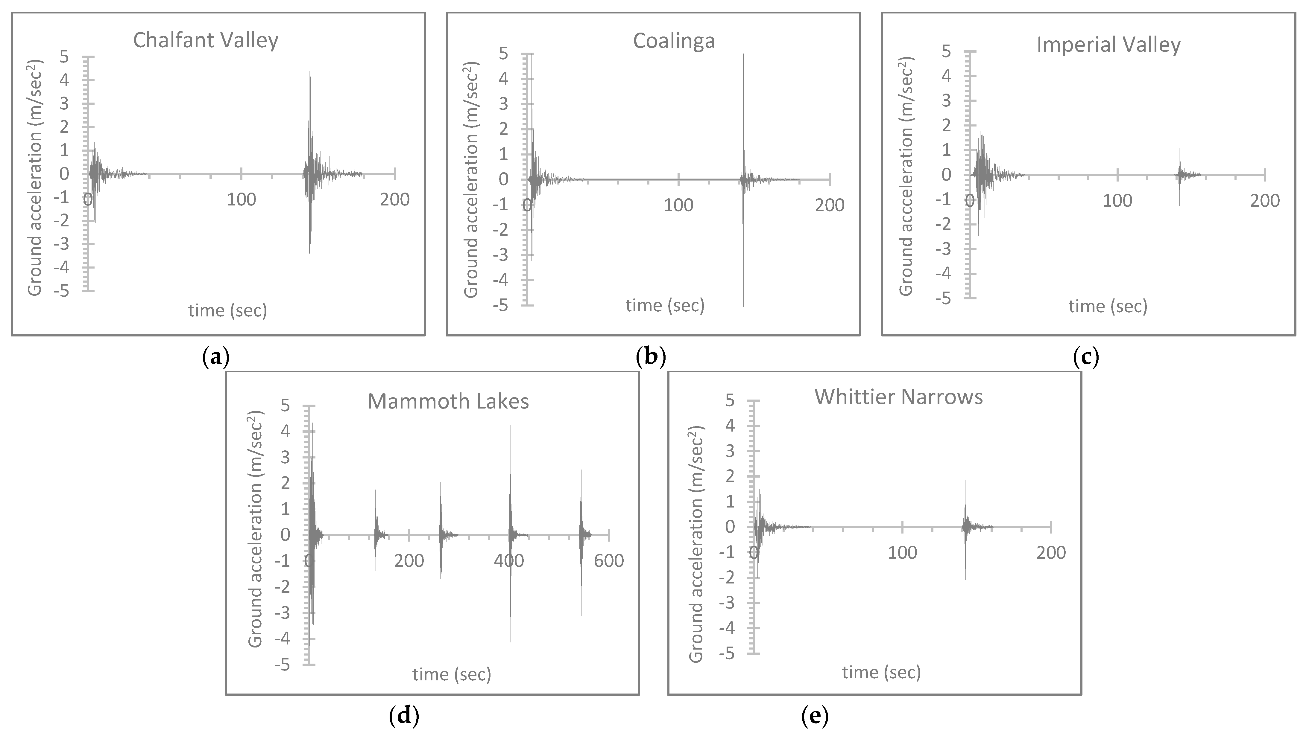
32] by employing the two horizontal components and the vertical ones of five seismic sequences, which are named as follows: “Chalfant Valley” (1986) consisting of two individual seismic excitations; “Coalinga” (1983) consisting of two individual seismic excitations; “Imperial Valley” (1979) consisting of two individual seismic excitations; “Mammoth Lakes” (1979) consisting of five individual seismic excitations; “Whittier Narrows” (1987) consisting of two individual seismic excitations. The sequential ground excitation list is presented in
Table 3, where the source accelerograms are downloaded from [
37], where more detailed seismological information on these excitations is available. The selection of sequential earthquakes is based on the extensive research of [
18,
19,
20,
21,
22]. Following the method of [
18,
19,
20,
21,
22], the successive seismic events of the same sequential ground motion are separated by a time frame of 100 seconds containing zero values for the excitation input, to calm down the building motion due to damping. In
Figure 3, the time-history ground acceleration plots are presented for the most intense horizontal direction of these sequential excitations, as considered by the measured data values from [
37], and plotted by [
38]. In the current NLTH analyses, the excitation refers to the whole multiple sequence, as in
Table 3. The comparison of the effect of single seismic events to multiple ones has already been investigated in-depth by [
18,
19,
20,
21,
22] and is not included in the target of the current study.
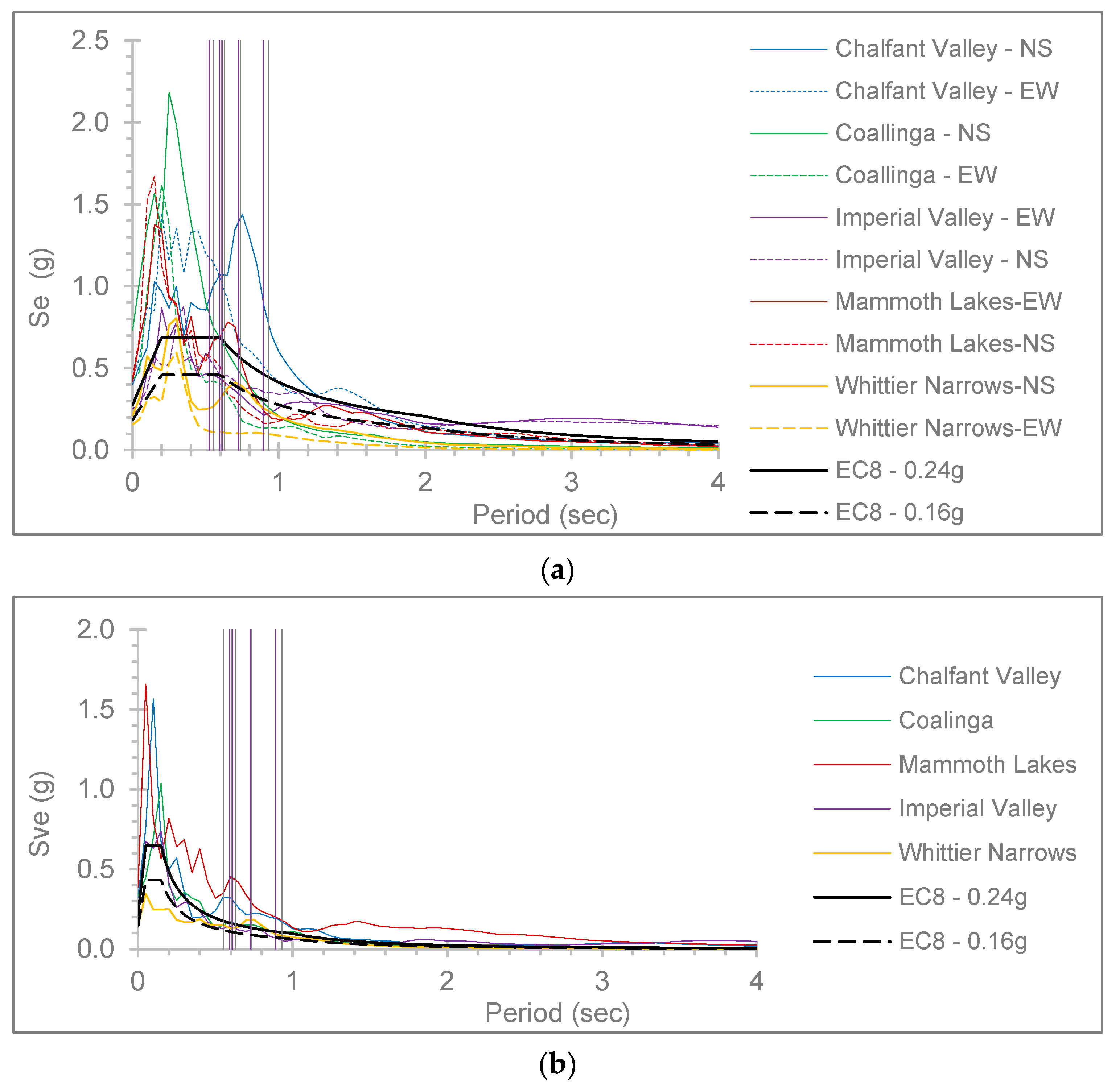
In the spectra of the ground excitations, as presented in
Figure 4, which are calculated by [
39] and plotted by [
38], the first mode (
Table 2) of the hybrid buildings is represented for evaluation of the plots with vertical lines by purple color for the rigid connection of the r/c part upon the steel one and grey color for the semi-pinned connection, respectively. In these spectra for the horizontal directions (
Figure 4a) and the vertical one (
Figure 4b), the design spectra of [
1] are plotted for the zone ground acceleration values of 0.24 g and 0.16 g following the respective assumptions which are mentioned in
Section 2. The compliance of the sequential ground excitations spectra is compared to the seismic design specifications [
1] in
Figure 4. The considered earthquake spectra are observed with generally higher values than the design spectra (
Figure 4), so they are considered adequate for the current aim of the study, as strong ground motions.
From the available literature [
7,
25,
26,
27,
28,
29,
30,
31], it is obvious that the excitation angle which is expressed here by the angle “φ” (
Figure 2), may strongly alter the seismic structural response. Based on the geometrical shape of the 3D hybrid r/c–steel building frames, in the current NLTH analyses, the excitation angles are considered as φ = 0°, 90° and φ = 45° (
Figure 2). In the NLTH analyses of this work, non-structural elements are omitted from the analysis model.
The arithmetic estimation of a uniform damping ratio for the NLTH analyses is performed according to the proposal of Sivandi-Pour et al. [
15,
16]. The calculated damping ratio values for each hybrid r/c–steel frame are presented in
Table 4, induced in the analysis model by [
32] and finally used for the performance of the current numerical investigation.
The possible non-linear behavior of reinforced concrete elements under intense loading is considered in the NLTH analyses by elastoplastic point hinges, which are placed at both ends in the analysis model by [
32] according to [
40], considering nonlinear material characteristics, such as stiffness and strength deterioration of elements, the post-yield hardening ratio taken as 5% [
40], the backbone moment rotation-curve as in [
40] and the stiffness reduction due to cracking, etc., following the provisions of [
40]. The stiffness degradation and strength deterioration are induced in the analysis model following the Takeda hysteresis model [
2,
32]. A possible shear failure of reinforced concrete elements is checked following the guidelines of EC8 [
1]. Similarly, point hinges are placed at both ends of steel members according to [
40] used in the analysis model by [
32], considering a 2% strain hardening. The restrictions of the elastoplastic hinge rotations of steel elements concerning the seismic performance levels follow the provisions of ASCE 41-17 [
40]. In the literature more detailed or sophisticated mechanical models may be available regarding the elastoplastic behavior of r/c or steel elements; however, here this simple procedure for the estimation of this elastoplastic behavior is followed which complies with a contemporary standard [
40], to remain within the target limits of the present study. This investigation examines the general dynamic behavior of hybrid model buildings by comparing the two aforementioned support examples, without interfering with the details of material mechanics, or details on the constitutive relationships of the materials, which are widely examined in the worldwide literature.
For each non-linear hybrid frame, the system of equations of motion has the form of
[
41], where
M and
C correspond, respectively, to the matrices of mass and viscous damping,
u corresponds to the vector of lateral structural displacement relative to the ground,
corresponds to the ground excitation,
I corresponds to the unit vector, and
F is the vector of the nodal internal forces, depending nonlinearly on the deformation and stiffness, while
corresponds to the differentiation of
u to the time
t [
41]. In [
32], the aforementioned system of equations was automatically formed and solved by stepwise time integration for each analysis model, while all analysis results were supplied by the respective postprocessors of [
32].
4. Response Results and Discussion
Currently, the dynamic response results of the considered hybrid frames subjected to the sequential ground excitations are presented and discussed. Diagrams of the greatest “inter-story drift ratio (IDR)”, “residual inter-story drift ratio (RIDR)”, and “peak floor acceleration (PFA)” [
7,
42] are given along with the height of the frames. These global parameters are selected similarly to previously mentioned research works, [
7,
18,
19,
26,
29,
30,
31], to serve better the purposes of the current study. This investigation aims to evaluate the general behavior of hybrid r/c–steel buildings designed with the previous assumptions while comparing two connection examples, by using the selected comparison parameters which are already proven satisfying for the evaluation of the seismic behavior of r/c or hybrid structures in the literature, [
30,
31,
42]. In the literature, there can be found details of the cumulative damage effect of sequential earthquakes on the structural response [
19,
43,
44], which is not accounted for here, because this work studies the general behavior of hybrid models under sequential earthquakes comparing the rigid or semi-pinned support of the steel part on the r/c part. The currently shown results refer to the entire sequential earthquake, as observed in real circumstances. Concerning the examined boundary connections of the steel part with the reinforced concrete structure, i.e., rigid and semi-pinned (
Section 2), separate plots for these conditions are presented with respective notations in their title. In the presented plot legends, the diagrams for each earthquake, as plotted by [
38] through the analysis results obtained by [
32], are mentioned by the name of each earthquake (as in
Section 3 and
Table 3) followed by the symbols “0”, “45” or “90” concerning the examined earthquake incidence angles (as in
Section 3).
The following presented plots of IDR are commented on comparatively to the limit IDR values of FEMA-356 [
45] as mentioned here for convenience: regarding reinforced concrete frames, 1% corresponds to the “Immediate Occupancy” (IO) [
45] performance level; 2% corresponds to the “Life Safety” (LS) [
45] performance level; 4% corresponds to the “Collapse Prevention” (CP) [
45] performance level; 0.7%, 2.5% and 5% correspond to structural steel moment resisting frames, respectively [
45]. The limit RIDR values of FEMA-356 [
45] are mentioned here concerning the same performance levels IO, LS and CP, mentioned as negligible permanent, 1% and 4% for r/c frames, respectively; or negligible permanent, 1% and 5% for steel MRFs, respectively. Limit peak floor acceleration (PFA) values concerning the seismic performance of structures are not available in the literature. The maximum absolute values of PFA to the greatest absolute values of “peak ground acceleration” (“PGA”) [
7,
42], called “PFA/PGA” [
7,
42], of the entire sequential excitation are plotted for comparison purposes. The most detrimental plots of IDR, RIDR and PFA/PGA are presented here to save space. Selected plots of the analysis model with the worst formation of elastoplastic hinges are shown for selected ground motions following the limits of [
1,
40].
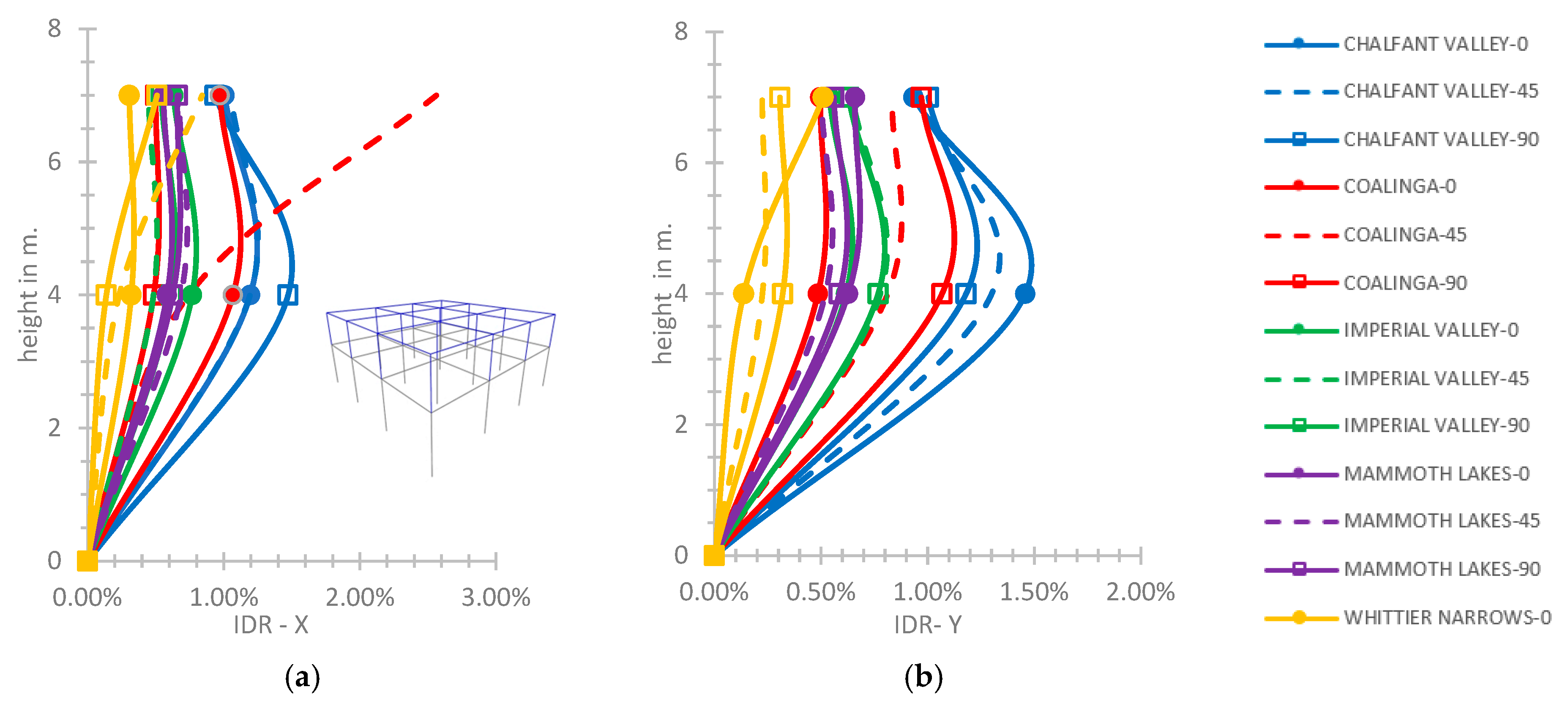
Starting from the two-story hybrid frame, as in
Figure 5, the greatest IDR-X value calculated is 1.47% and the greatest IDR-Y value is 1.46% at the height of 4.0 m, within the limits of the CP performance level [
45] concerning the rigid connection of the steel and r/c parts. The local higher value of IDR on the X axis equal to 2.56% for the earthquake of Coalinga and φ = 45° (
Figure 5a) is observed at the top of the hybrid building, within the limit of the CP performance level [
45].
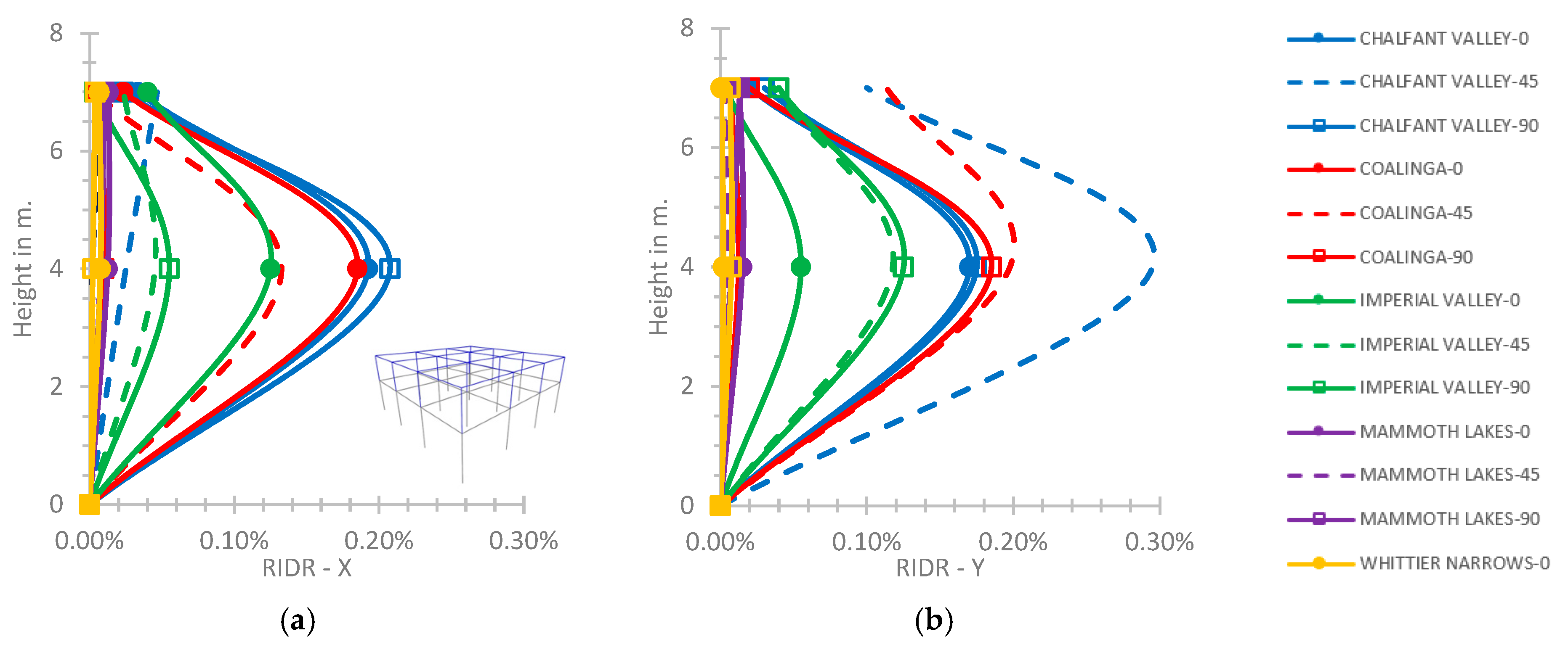
The maximum values of RIDR, as shown in
Figure 6 for the rigid connection of the steel story with the lower story, are 0.21% on the X axis for the ground excitation of Chalfant Valley with φ = 90° and 0.30% on the Y axis for the same excitation with φ = 45° at height of 4.0 m, within the limits of the IO performance level [
45].
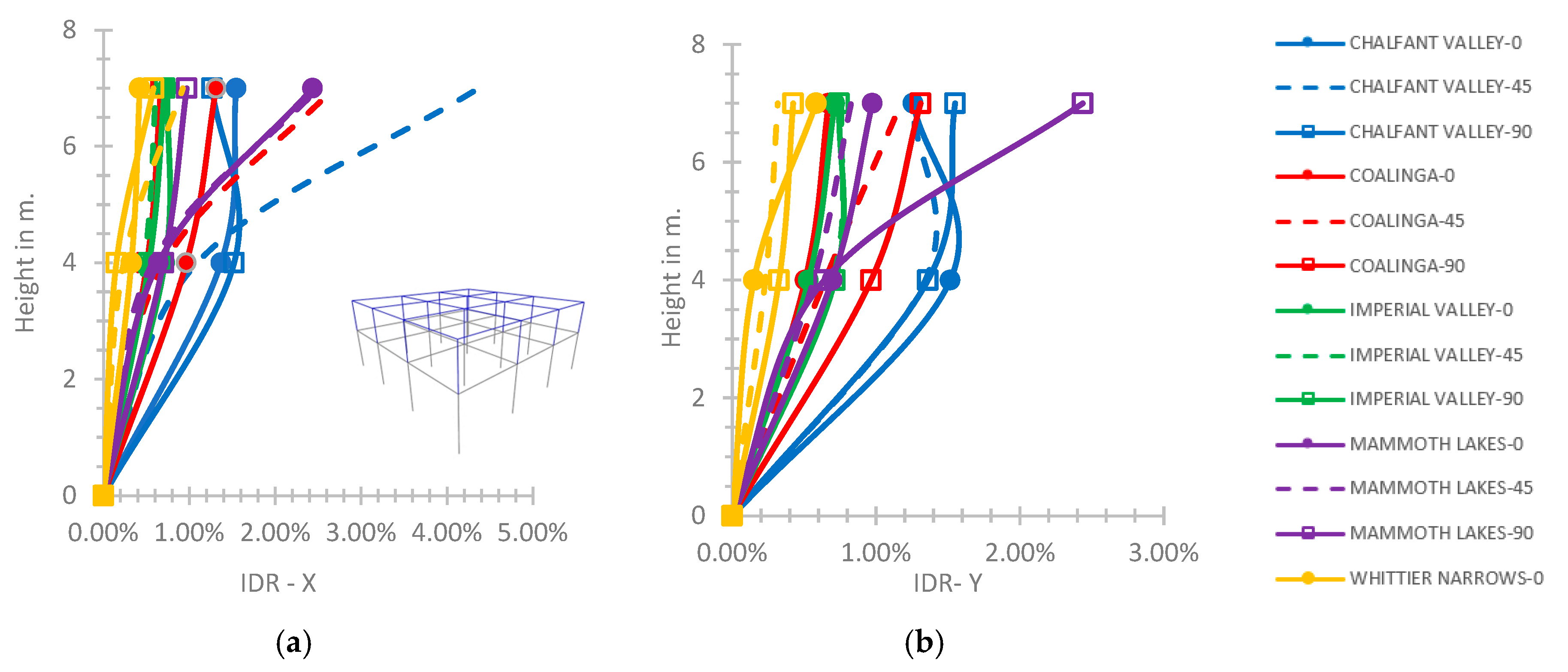
At the two-story hybrid frame, comparing the semi-pinned connection to the rigid one (
Figure 7a), the IDR-X increases variably along with the frame height and has a maximum value of 4.36% at the building top, which is over the limit of CP performance level [
45] and greater by 70% than the respective maximum value for the rigid support (
Figure 7a). As in
Figure 7b, for the semi-pinned support, the IDR-Y increases along with the building height with a maximum value at the building top of 2.44% for the Mammoth Lakes with φ = 90°, within the limit of the CP performance level [
45], which is 2.5 times greater than the respective value for the rigid support of
Figure 5b.
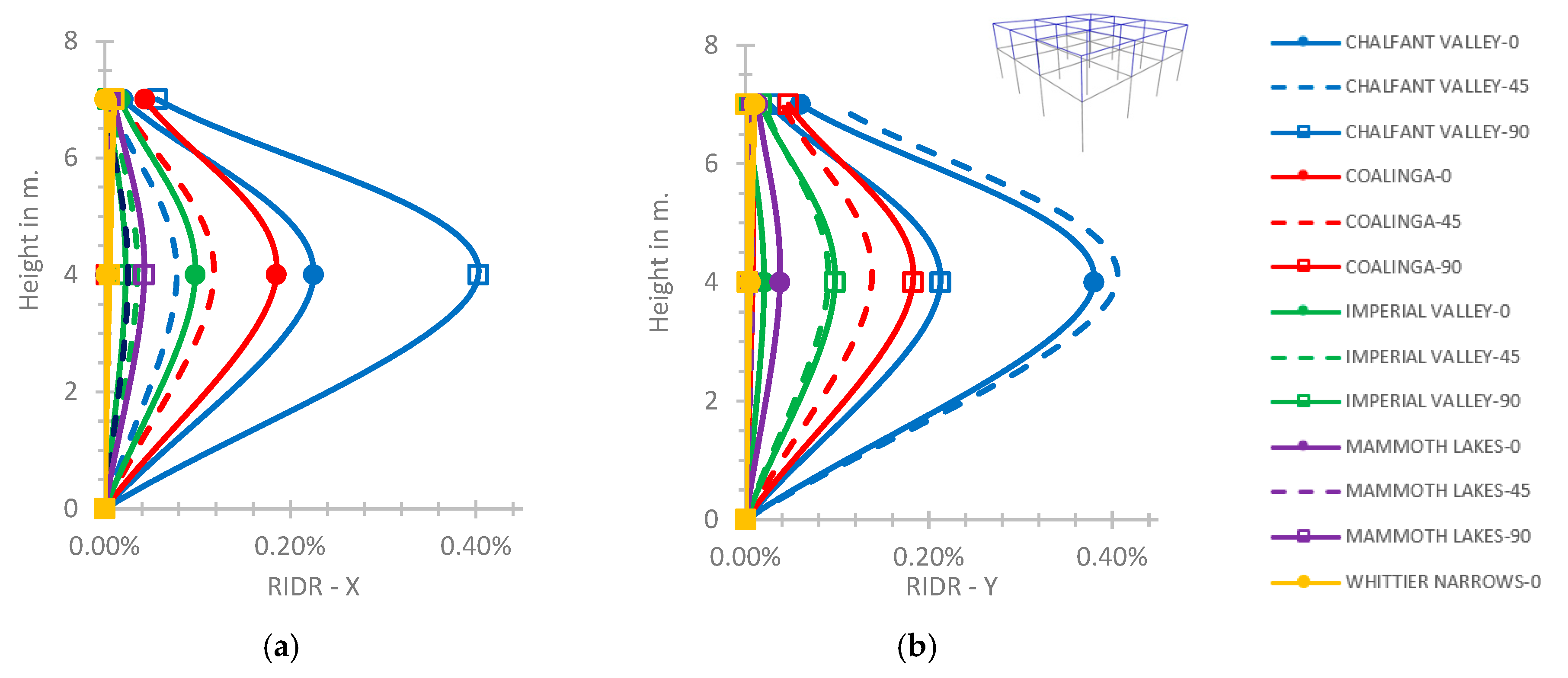
As shown in
Figure 8, the corresponding values of RIDR for the semi-pinned support are greater by almost 2 times and 1.4 times on the X and Y axis, compared to the respective plots for the rigid support of
Figure 6. The RIDR plot values of
Figure 8 for the semi-pinned support are still within the limits of the IO performance level [
45].
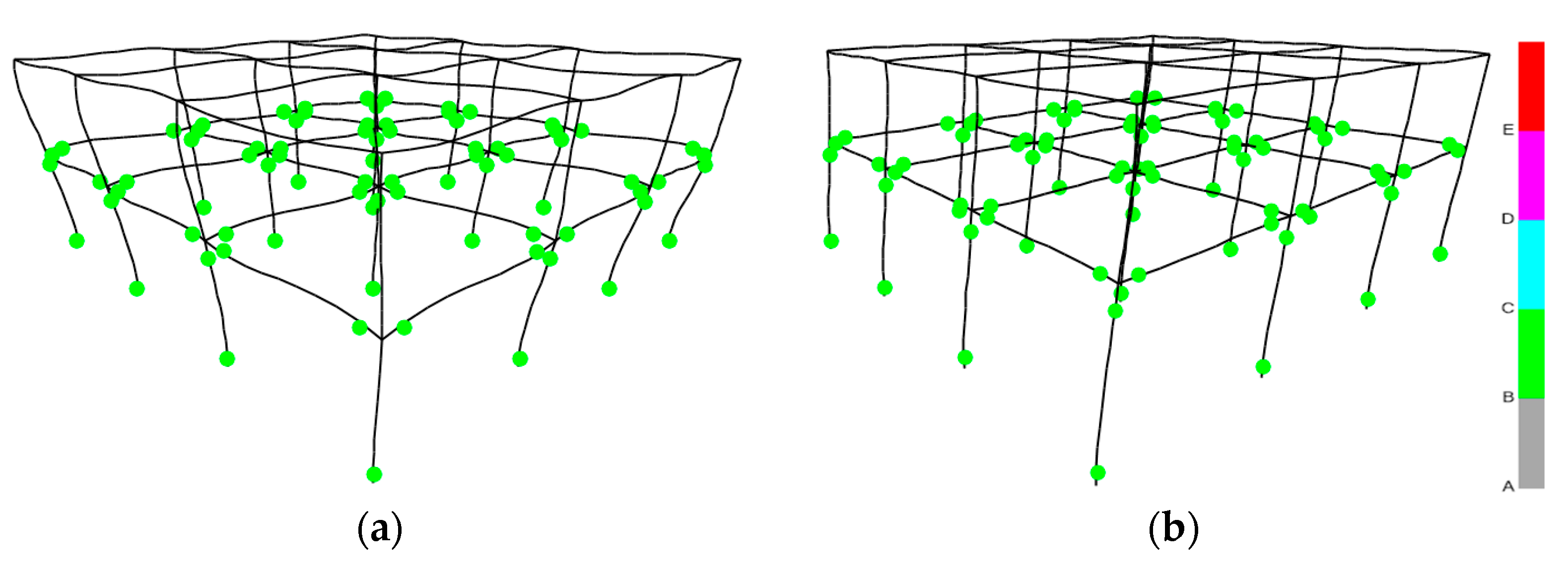
Concerning the two-story hybrid frame (
Figure 9), the elastoplastic hinges are within the limit “C” for the r/c story, while the structural steel elements exhibit elastic behavior. A similar elastoplastic behavior of the two-story hybrid building is observed for both rigid or semi-pinned connections of the second story with the first one for the current NLTH analyses, as in
Figure 7a,b, plotted by [
32].
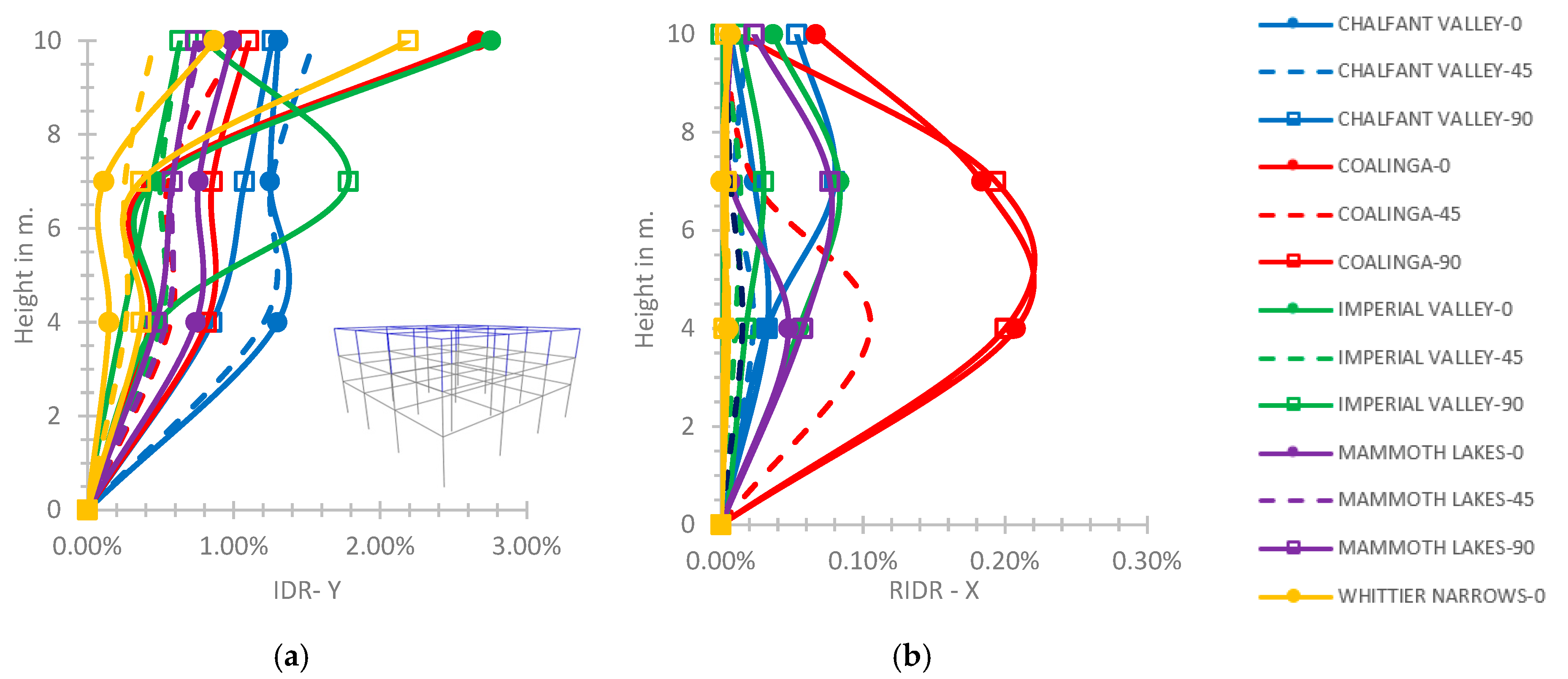
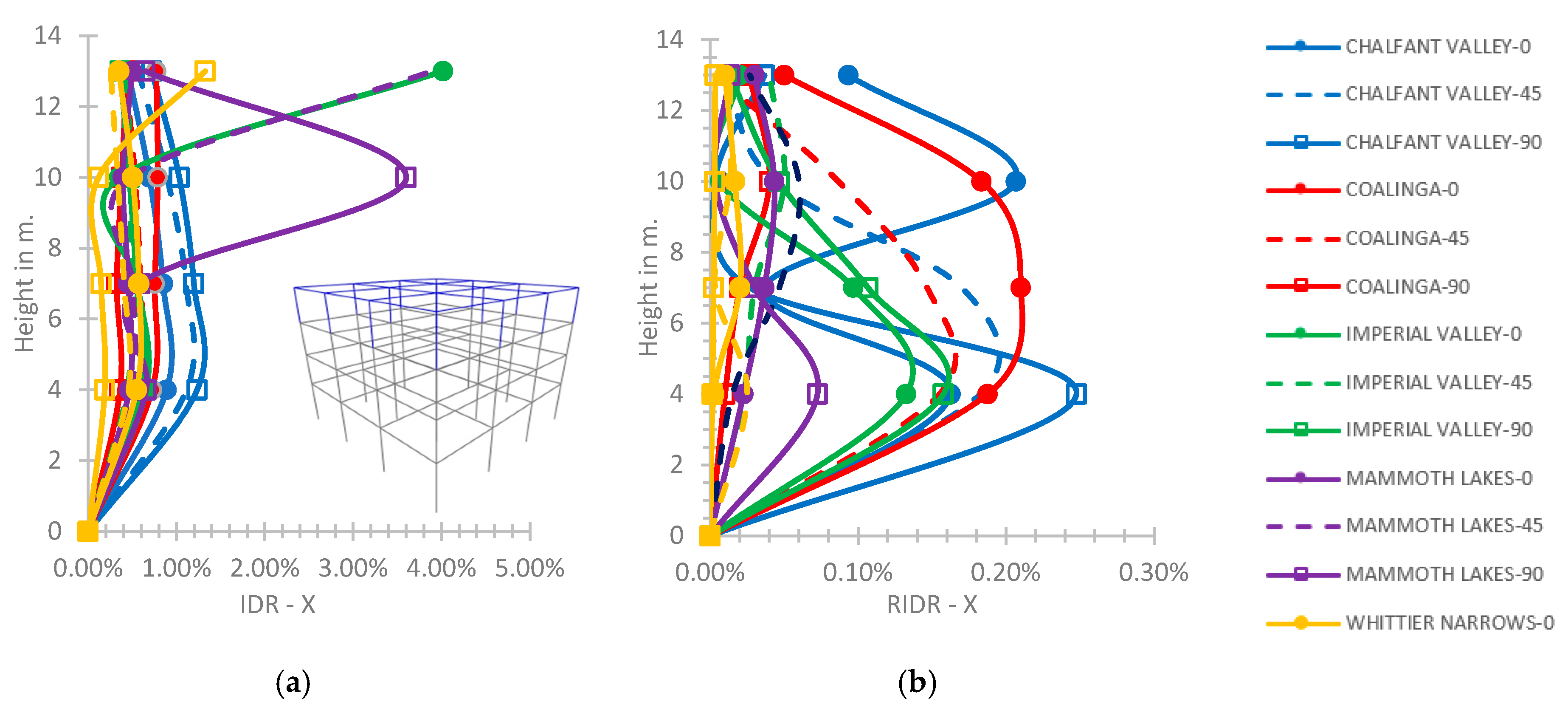
At the three-story hybrid frame, as shown in
Figure 10a, for the semi-pinned connection of the steel story on the lower reinforced concrete ones, a maximum IDR equal to 2.76%, on the Y axis is observed at the height of 10.0 m for the earthquake of Imperial Valley with φ = 0°. Regarding the semi-pinned connection of the third story on the second one, the maximum value of RIDR on the X axis is observed at the height of 4.0 m equal to 0.21% for the Coalinga earthquake, φ = 0° (
Figure 10b). For the three-story hybrid building, the greatest IDR-X and IDR-Y values are within the CP performance level [
45] for both supporting conditions, while the RIDR plot values are within the IO performance level [
45]. However, the general values of IDR plots (
Figure 10) tend to be greater by 13–29% on the higher stories for the semi-pinned connection of the third story with the second one, compared to a rigid support, respectively. The general values of RIDR plots tend to be greater by 1–2% for the semi-pinned connection of the steel part on the lower part compared to a rigid support.
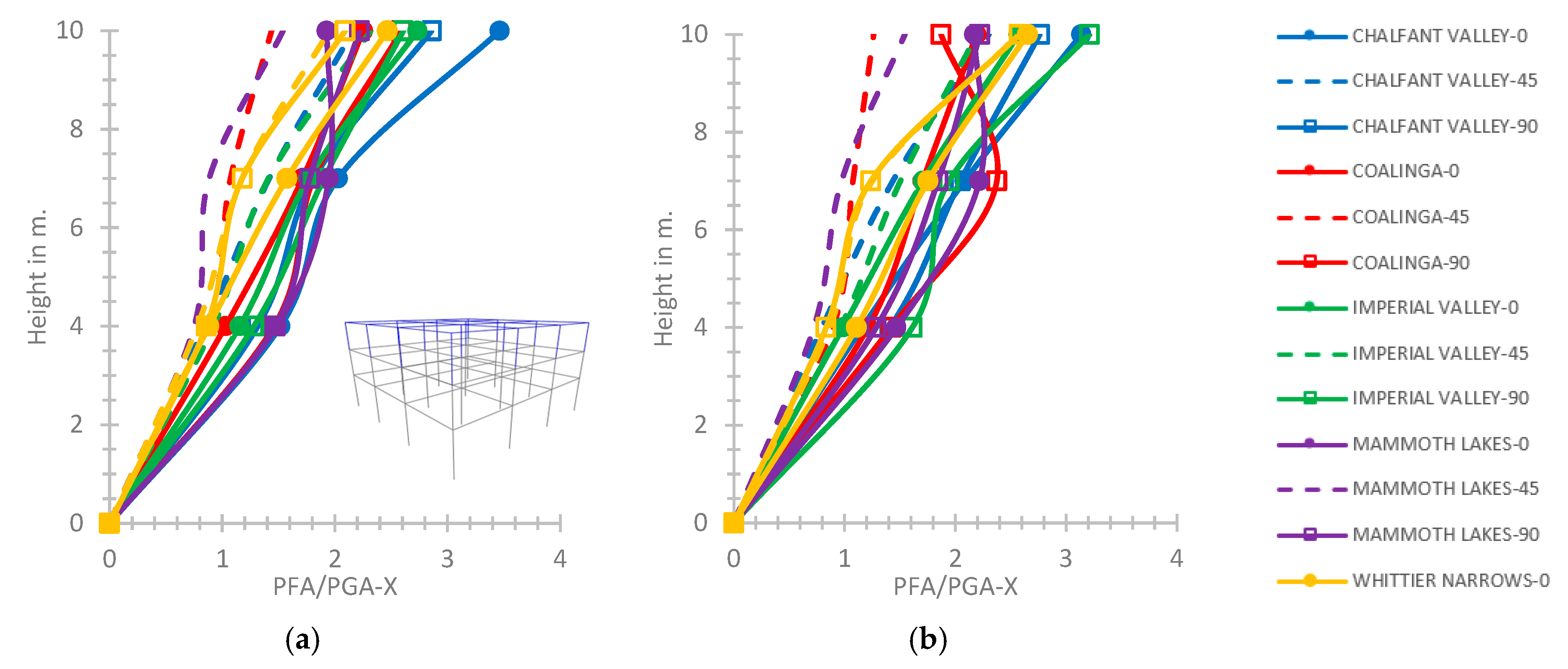
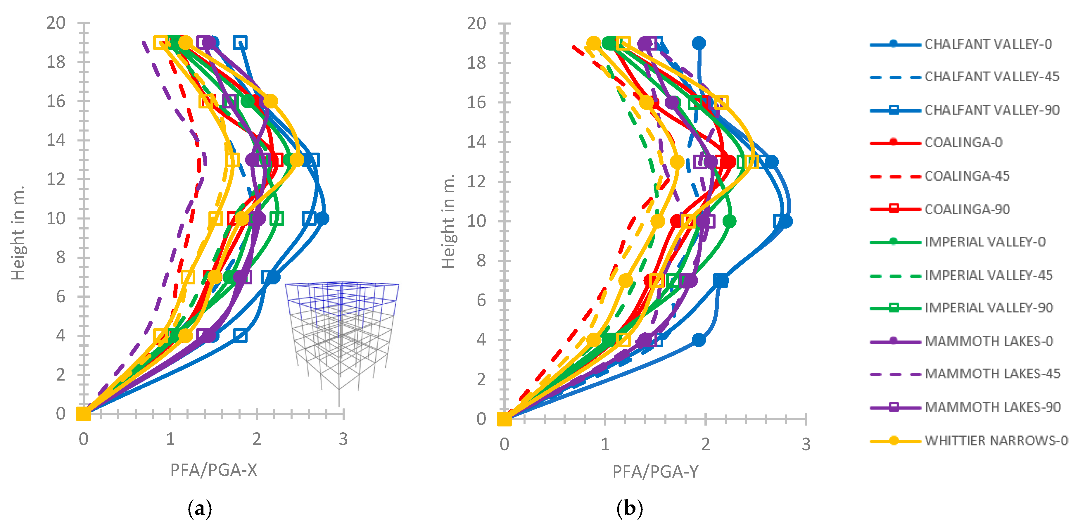
As shown in
Figure 11a, the greatest PFA/PGA on the X axis is 3.46 at the top of the three-story hybrid frame for the Chalfant Valley with φ = 0° regarding the rigid connection of the third story with the second story. The greatest value of PFA/PGA on the X axis is observed as 3.21 for the Imperial Valley excitation with φ = 90° for the semi-pinned support (
Figure 11b). The greatest value of PFA/PGA on the Y axis is 3.44 for the rigid connection of the upper part with the lower part and 3.21 for the semi-pinned support, respectively.
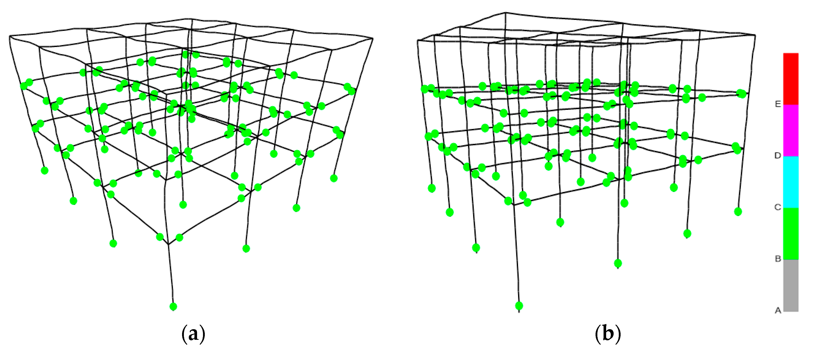
As shown in
Figure 12, which is plotted by [
32], the hinge formation of the three-story hybrid frame under the Coalinga excitation shows that the behavior of the structural r/c hinges is within the ultimate yielding bending moment limits “C” [
1,
40], while the steel elements exhibit elastic behavior. The elastoplastic behavior of the three-story hybrid building is similar for both supports, rigid or semi-pinned (
Figure 12).
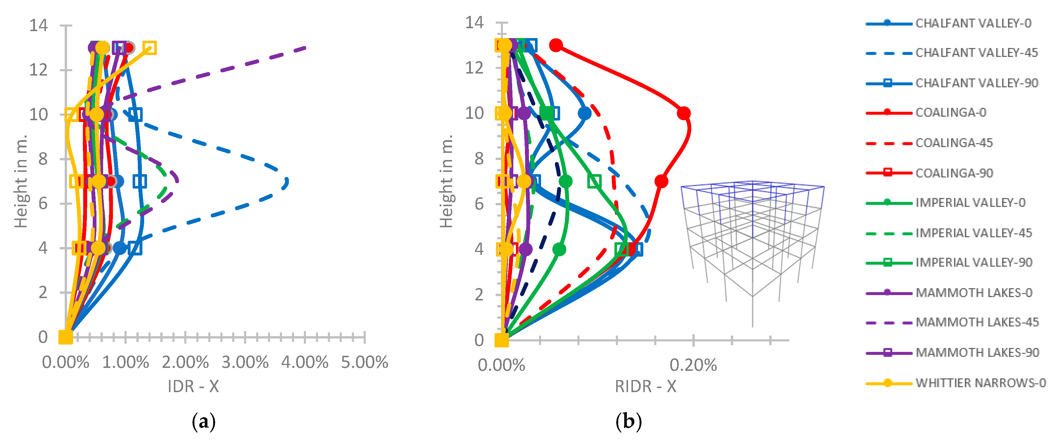
At the four-story frame for the rigid connection of the fourth story with the third one, the IDR-X has an increased numerical range, as compared to the lower previous hybrid buildings, even up to 4.02% at the height of 13.0 m for the Mammoth Lakes with φ = 45°, which is slightly over the limit of the CP performance level [
45], as shown in
Figure 13a. A similar range of values of the IDR plot is noted in the Y axis for the rigid support, not shown here to save space. The RIDR-X for the rigid connection of the fourth story with the third one (
Figure 13b), has a maximum value of 0.25% at the height of 4.0m for the earthquake of Chalfant Valley with φ = 90°, within the LS level [
45].
Taking into account the semi-pinned connection of the fourth story with the third one of the four-story hybrid frame (
Figure 14a), the IDR-X axis has a maximum value of 3.99% at the highest floor of the hybrid frame for the excitation of Mammoth Lakes with φ = 45°. Similarly, as shown in
Figure 14b, the RIDR has a maximum value of 0.19% at 10.0 m height for the ground excitation of Coalinga with φ = 0°. Generally, for the four-story hybrid building, the IDR plots have a range of values within the CP performance level [
45] in both axes for both considered supporting conditions, while the RIDR plots have a range of values within the LS performance level [
45], respectively.
For the four-story hybrid building, the PFA/PGA plot on the Y axis regarding the rigid connection of the fourth story with the third one tends to increase along with the height presenting a maximum value of 3.58 at the building top for the Imperial Valley with φ = 0° (
Figure 15a). For the semi-pinned connection of the fourth story with the third one, the ratio of PFA/PGA on the Y axis shows greater general values along with the building height, up to 3.01 at the building top for the Chalfant Valley with φ = 0°, as in
Figure 15b.
The behavior of elastoplastic hinges is similar for both connections, rigid or semi-pinned, of the steel story with the r/c stories, as observed in
Figure 16 (plotted by [
32]), where the r/c hinges are within the ultimate bending moment limit, while the steel elements exhibit elastic behavior. The behavior of the hinges of the four-story hybrid building in
Figure 16 is similar to the previous two- and three-story hybrid buildings presented in previous
Figure 9 and
Figure 12.
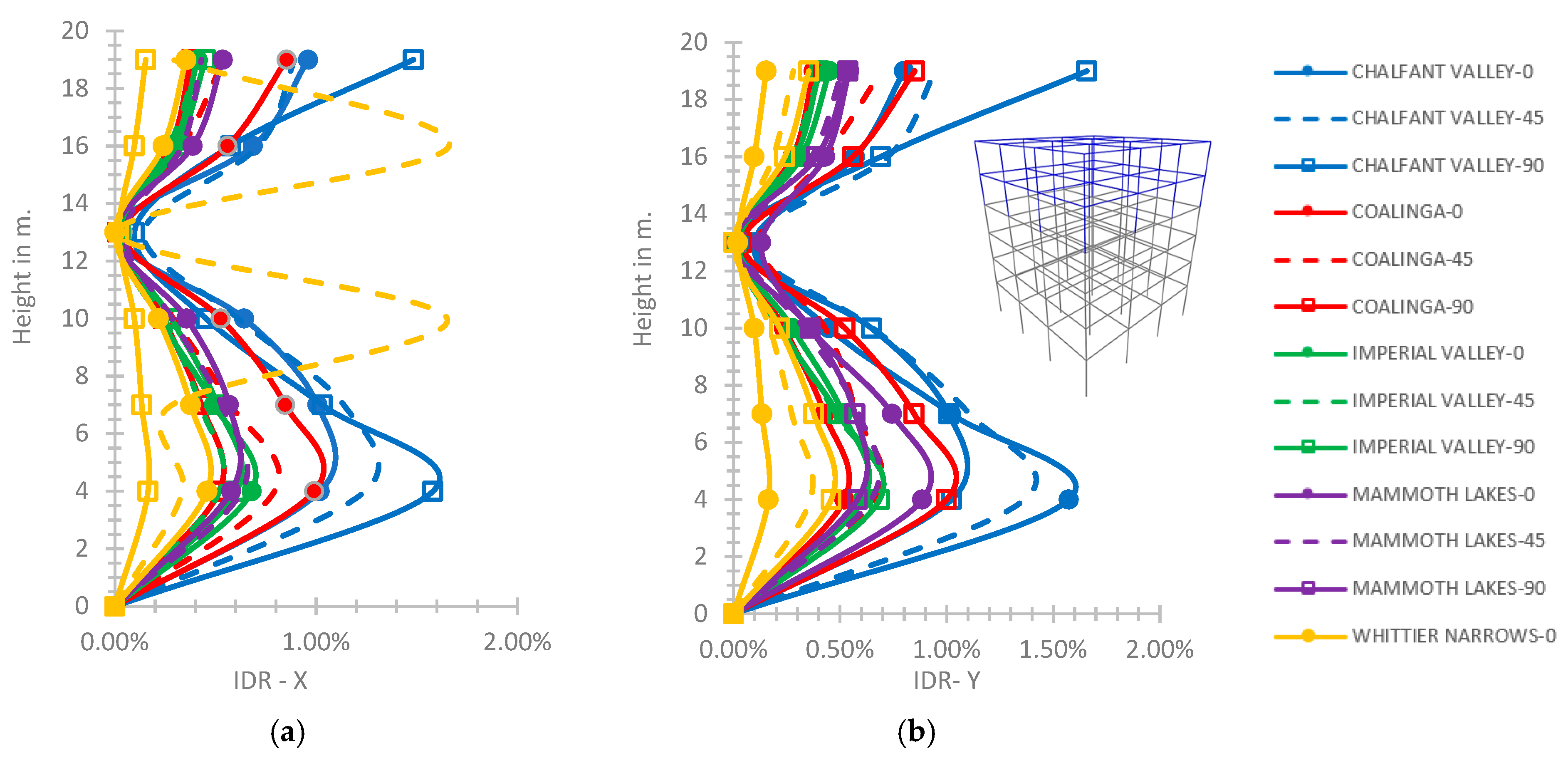
As observed in
Figure 17a, at the five-story frame, regarding the semi-pinned connection of the fourth story with the third one, the maximum value of IDR on the X axis is 4.16% at the building top, which is greater by 3.2% in comparison with the rigid case. As presented in
Figure 17a, the plotline for the Chalfant Valley earthquake with φ = 90° is omitted due to IDR values greater than the limits of [
45] indicating a structural failure. As shown in
Figure 17b, for the case of semi-pinned support, the maximum value of IDR on the Y axis is 2.9% at the building top, which is less by 28% as compared to the rigid support, where the curve for the Chalfant Valley earthquake with φ = 0° is left out due to the maximum observed IDR values much greater than the limits of [
45] showing a structural failure. Regarding the rigid connection of the fourth story with the third one, the maximum IDR-X is 4.03% at the top of the building and 4.03% on the Y axis, respectively, which is slightly over the CP performance level [
45]; these relevant plots are not shown here to save space.
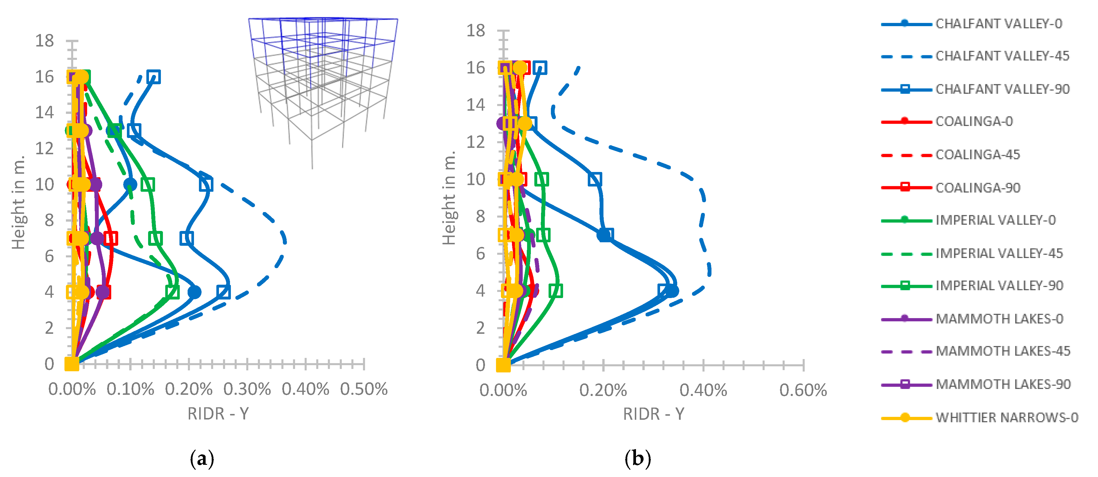
The RIDR-X and RIDR-Y of the five-story frame have general values lower than the limit of IO performance level [
45] for both connections of the fourth story with the third one. The RIDR on the Y axis regarding the rigid connection of the fourth story with the third one presents a maximum value of 0.36% at the height of 7.0 m for the Chalfant Valley earthquake with φ = 45° (
Figure 18a). Concerning the semi-pinned support (
Figure 18b), the RIDR on the Y axis has a maximum value of 0.39% for the same previous earthquake, which is greater by 8.3% than for the rigid support.
The PFA/PGA ratio increases along with the height of the five-story hybrid building on both horizontal axes up to 2.85 for the rigid support case; and up to 3.25 for the semi-pinned case.
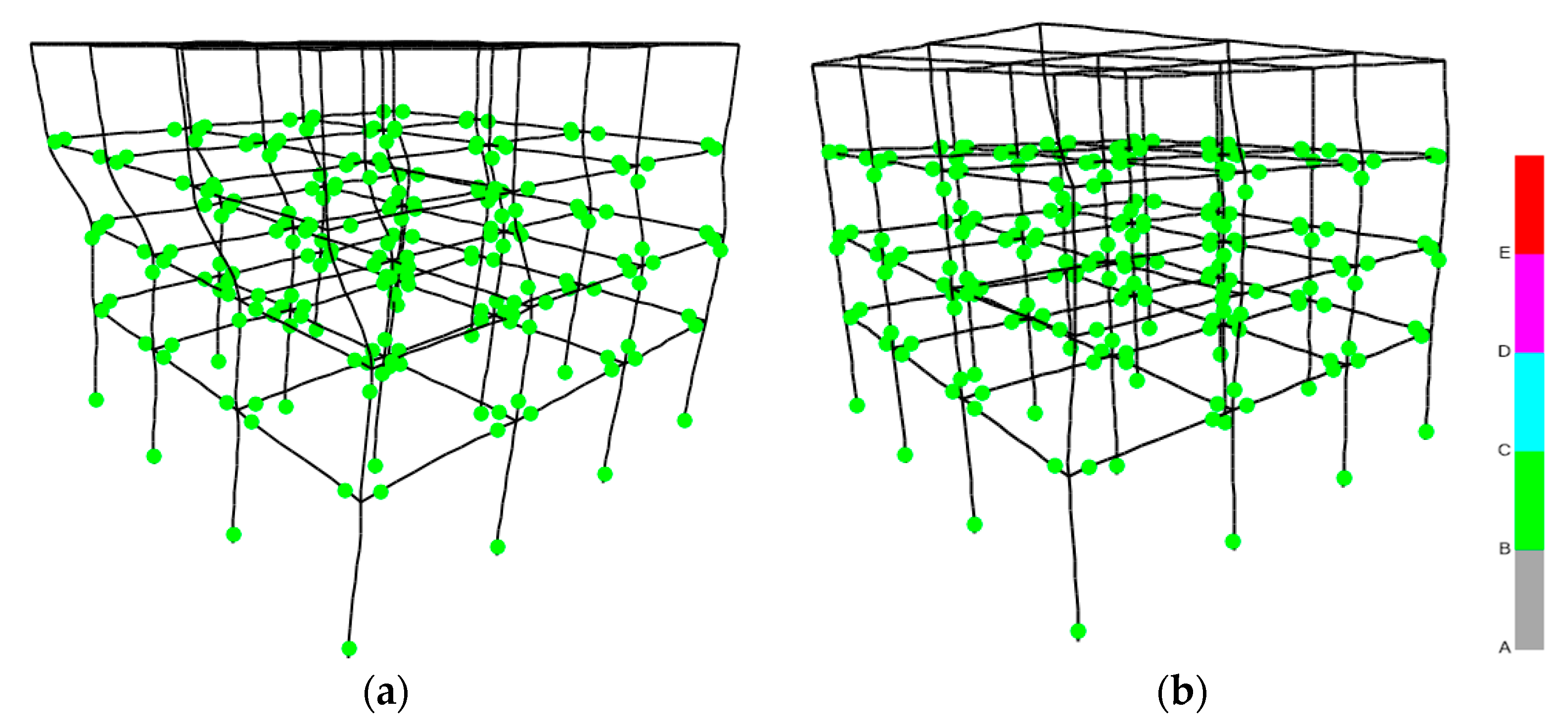
As presented in
Figure 19a (plotted by [
32]), the worst hinge formation of the five-story hybrid building for the rigid supporting condition shows that the r/c part is within the limit of ultimate bending moments and the steel part exhibits an elastic behavior for the Chalfant Valley earthquake with φ = 0°. As observed in
Figure 19b, for the semi-pinned case, the worst hinge formation of the five-story hybrid building shows that the steel part and the r/c part are within the limit of ultimate bending moments for the Chalfant Valley earthquake with φ = 0° [
32]. The worst hinge formation of the five-story hybrid building for the semi-pinned supporting case (
Figure 19b,c) is observed alongside with the locally great values of IDR on the horizontal axes (
Figure 17) over the CP performance level [
45] and indicates failure of the hybrid building under this earthquake, as previously mentioned.
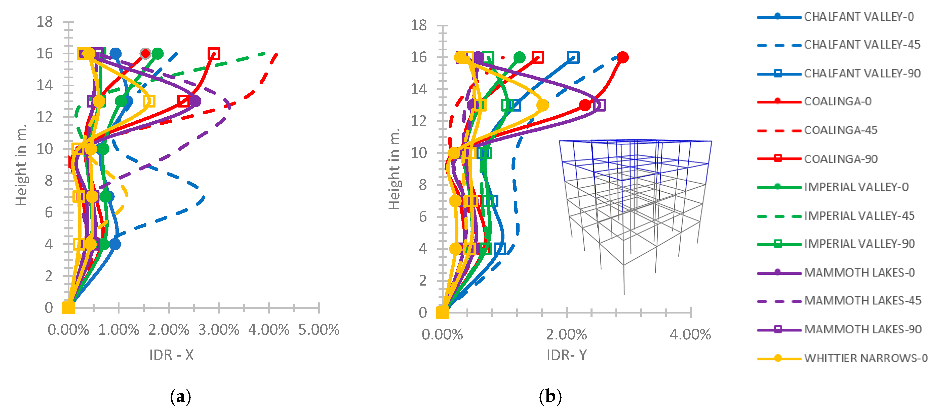
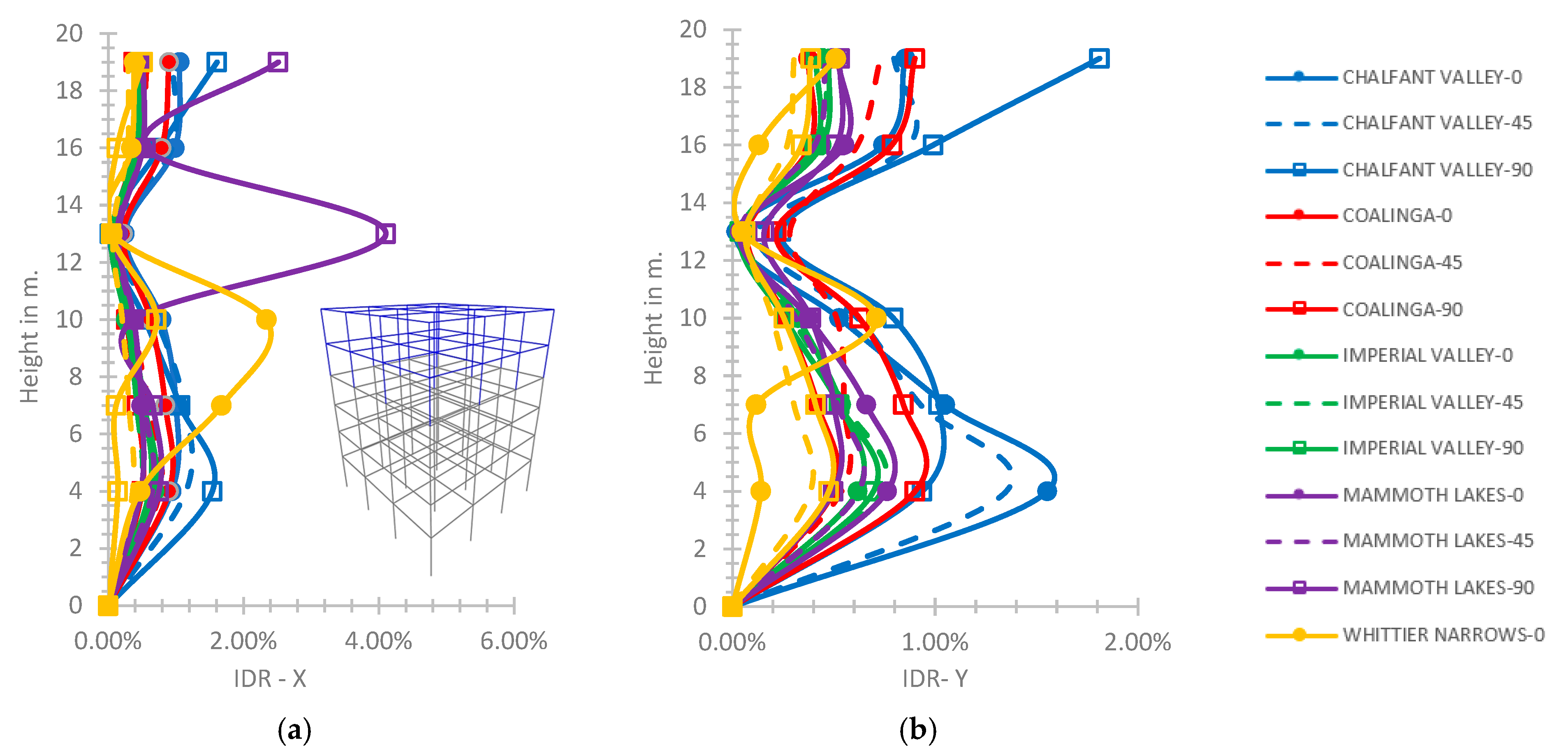
At the six-story hybrid frame for the rigid connection of the fifth story with the fourth one (
Figure 20), the maximum calculated value of the IDR-X axis is 1.66% at the height of 13.0 m, which is within the limit of LS performance level [
45], and the respective one on the Y axis is 1.66% at the building top. In
Figure 20, the plot line for the earthquake of Mammoth Lakes with φ = 90° is omitted due to its maximum IDR values greater than the limits of CP [
45] indicating a building failure. Considering the semi-pinned support, as shown in
Figure 21, the maximum value of IDR on the X axis is calculated as 4.1% at the height of 13.0 m for the earthquake of Mammoth Lakes with φ = 90° and the respective value on the Y axis is 1.81% at the building top for the earthquake of Chalfant Valley with φ = 90°.
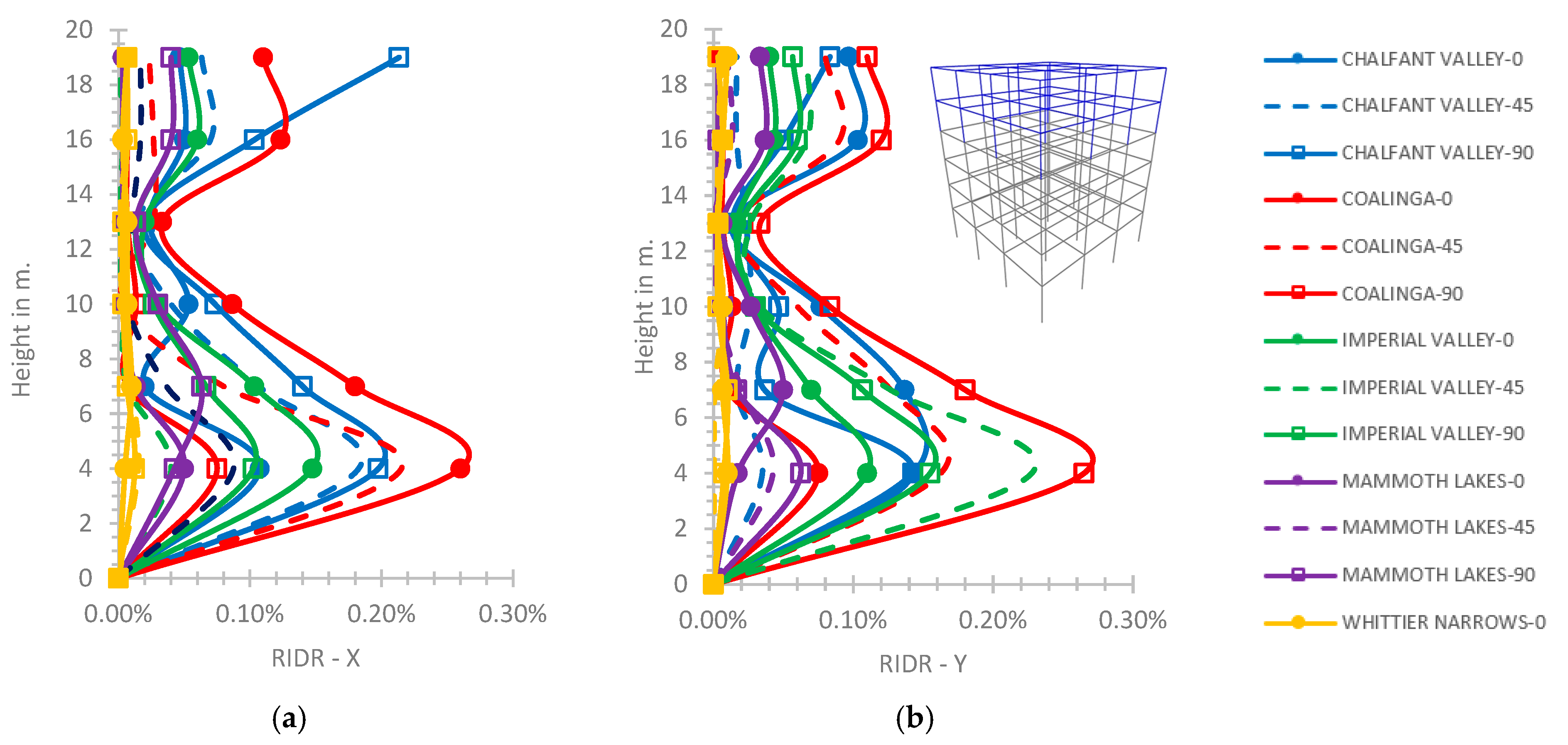
At the six-story hybrid building, the RIDR plots have general values within the limit of IO performance level [
45] for both rigid and semi-pinned connections of the fifth story with the fourth one. As indicatively presented in
Figure 22 for the semi-pinned support, the maximum RIDR calculated value is 0.26% on the X axis for the Coalinga ground excitation with φ = 0° at the height of 4.0 m; and 0.27% on the Y axis at the same height for the same excitation with φ = 0°. At the six-story hybrid building, the PFA/PGA plots tend to increase variably with a maximum value calculated as 2.76 on the X axis at the height of 13.0 m and 2.8 on the Y axis at the same height for the Chalfant Valley earthquake with φ = 0°, as indicatively shown in
Figure 23, for the rigid connection of the fifth story with the fourth one.
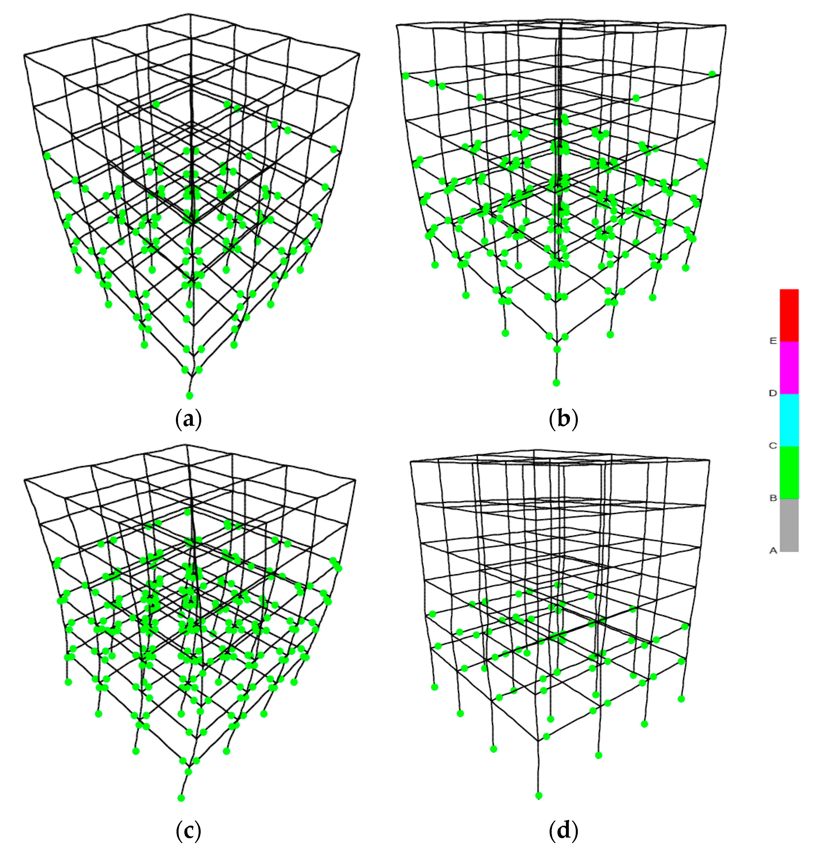
The hinge formation of the six-story hybrid frame for the rigid connection case, as in
Figure 24a,c [
32], shows that the r/c part has an acceptable behavior where the hinges are below the “ultimate bending moment limit” [
40] and the steel part has an elastic behavior. As in
Figure 24b,d, [
32], for the semi-pinned connection case, the hinges at the six-story hybrid frame show an elastoplastic behavior below the limit “C” [
1,
40].
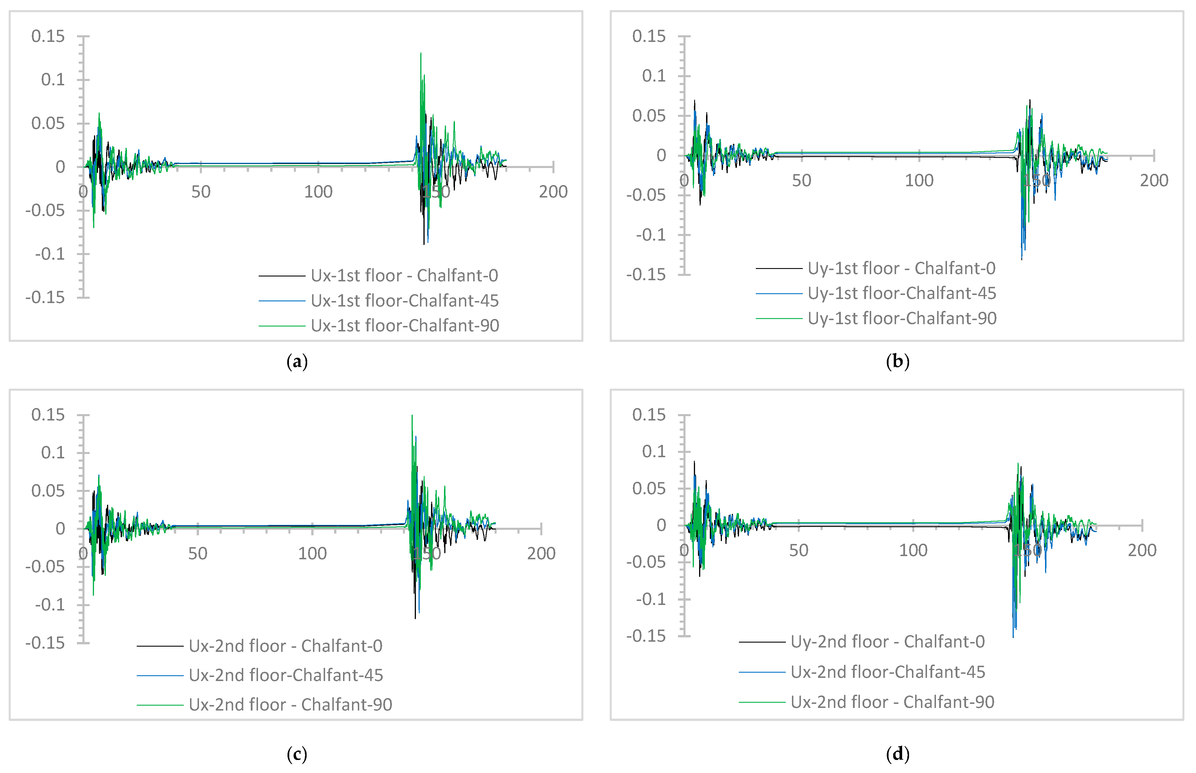
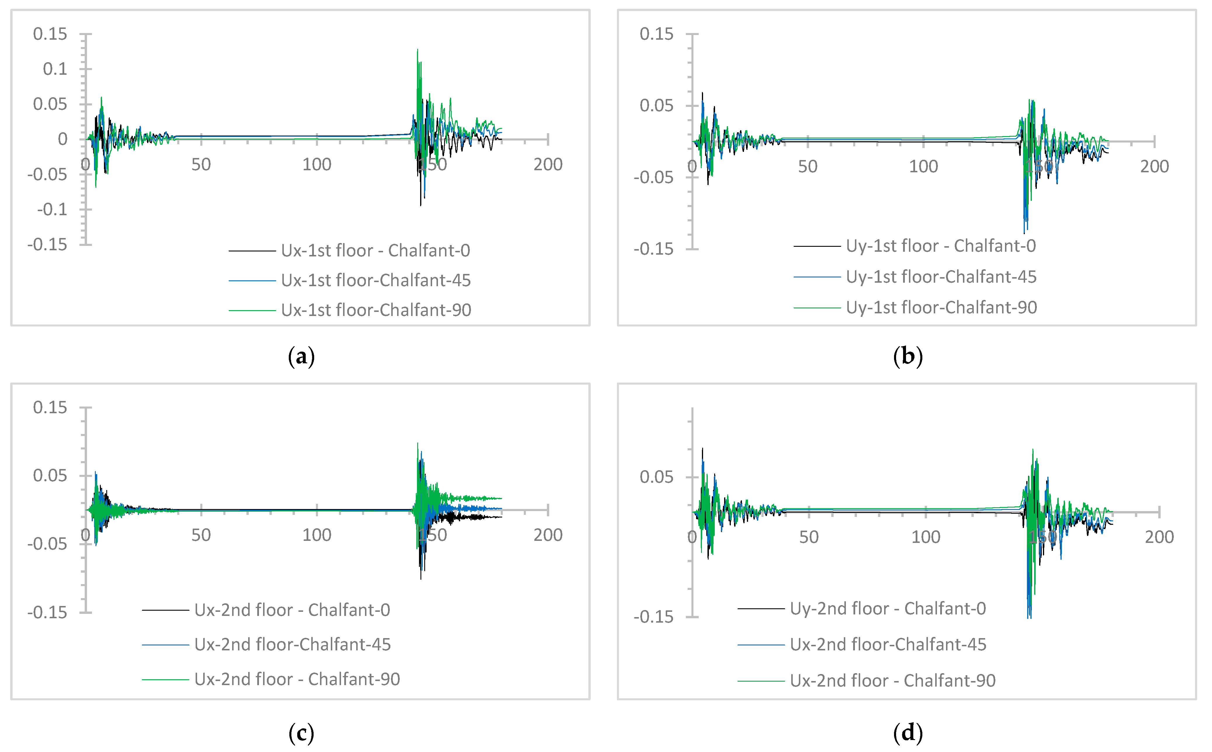
Some selected plots of the time history response of the hybrid models are presented for comparison purposes. Due to space limitations, indicatively, the time history plots of the absolute horizontal displacements, “Ux” and “Uy” in the X and Y axis, respectively, are given for the two-story hybrid frame subjected to the Chalfant Valley excitation, in the three considered incidence angles, for the rigid connection (
Figure 25) and the semi-pinned connection (
Figure 26) of the steel story upon the r/c one, provided by [
32]. At the first and second floors, slightly greater general absolute values of Ux are observed for the semi-pinned connection (
Figure 26a,c) compared to the rigid connection (
Figure 25a,c). On the first floor, slightly smaller absolute values of Uy are observed for the semi-pinned connection (
Figure 26b) compared to the rigid connection (
Figure 25b). On the second floor, slightly higher absolute values of Uy are shown for the semi-pinned case (
Figure 26c) in comparison to the rigid case (
Figure 25d).
Based on the presented response plots of the hybrid buildings under NLTH analyses, the excitation direction alters the analysis results in a varying way for each parameter. In general, the angles 0° and 90°, which are along the horizontal axes of the hybrid buildings, tend to be more detrimental to the seismic response results than the angle of 45°. However, there are examples in the presented plots, for example, in
Figure 3,
Figure 4,
Figure 5,
Figure 10,
Figure 11,
Figure 16,
Figure 17 and
Figure 19, where the angle of 45° provides worse response results than the other angles. Therefore, the selected earthquake incidence angles are crucial in the investigation of the results of the NLTH analyses, without the ability to make a separation on the most critical angle. Furthermore, the failure limit of structural elements in shear is not exceeded, as checked by [
1] for the current NLTH analyses of the examined hybrid r/c–steel buildings. The current investigation of hybrid r/c–steel frames subjected to sequential earthquakes by NLTH analyses shows that the sequential type of ground motion may strongly affect the hybrid frame response.


