Article

M-Ary Direct Modulation Chirp Spread Spectrum for Spectrally Efficient Communications

by
Jocelyn Edinio Zacko Gbadoubissa
1,2,
Ado Adamou Abba Ari
1,3,
Emanuel Radoi
4,* and
Abdelhak Mourad Gueroui
3
1
Department of Computer Science, University of Maroua, Maroua P.O. Box 814, Cameroon
2
African Institute for Mathematical Sciences, Limbé P.O. Box 608, Cameroon
3
DAVID Lab, University of Versailles Saint-Quentin-en-Yvelines, 45 Avenue des États-Unis, 78000 Versailles, France
4
Lab-STICC, CNRS, Univ Brest, CS 93837, 6 Avenue Le Gorgeu, CEDEX 3, 29238 Brest, France
*
Author to whom correspondence should be addressed.
Information 2023, 14(6), 323; https://doi.org/10.3390/info14060323
Submission received: 31 March 2023 / Revised: 30 May 2023 / Accepted: 3 June 2023 / Published: 6 June 2023
(This article belongs to the Special Issue Advances in Wireless Communications Systems)

Abstract

:
Spread spectrum techniques, such as the Chirp Spread Spectrum (CSS) used by LoRa technology, are important for machine-to-machine communication in the context of the Internet of Things. They offer high processing gain, reliable communication over long ranges, robustness to interference and noise in harsh environments, etc. However, these features are compromised by their poor spectral efficiency, resulting in a very low data transmission rate. This paper deals with a spectrally efficient variant of CSS. The system uses M-ary phase keying to modulate the data and exploits CSS’s properties to transmit the modulated symbols as overlapping chirps. The overlapping of chirp signals may affect the system performance due to inter-symbol interference. Therefore, we analyse the relationship between the number of overlaps and the effect of inter-symbol interference (ISI), and we also determine the BER expression as a function of the number of overlaps. Finally, we derive the optimal number of overlapping symbols that corresponds to the minimum error probability.

1. Introduction

The concept of spread spectrum modulation is based on the idea of using more bandwidth than the minimum required to transmit information. Spread spectrum modulation ensures transmission performance in environments with interference and fading, such as dense wireless sensor networks [1,2,3,4]. Some of the advantages of spread spectrum systems include selective addressing, code multiplexing, low-power spectral density, message confidentiality, high-resolution range, interference suppression capability, processing gain, and also a jamming margin [5].
Selective addressingis possible by using sequences of modulation codes to recognize a particular signal. Assigning a particular code to a given receiver allows it to be contacted only by a transmitter that uses that code to modulate its signal. Code division multiplexing is similar in that some transmitters and receivers can operate on the same frequency at the same time using different codes. Transmitted signals with low-power spectral density are advantageous for preventing interference with other systems and providing a low probability of interception. The low-power spectral density of spread spectrum signals is an inherent property due to bandwidth expansion. Message confidentiality (or privacy) is also inherent in spread spectrum signals because of their coded transmission format. Spread spectrum systems have been built to use all types of codes, from the relatively simple maximum linear code to truly secure non-linear types of encryption. Direct sequence spread spectrum signals stand out by providing high-resolution range measurements. This property is due to the high-speed codes used for modulation.
Among the spread spectrum techniques, the direct sequence spread spectrum (DSSS) and the chirp spread spectrum are the most studied. The spread spectrum signal of DSSS across the transmission interface is generated by mixing the information with a pseudo-random noise (PN) code, which is a deterministic binary sequence that exhibits good randomness properties [6,7]. The DSSS has strong rejection ability against multi-path propagation interference and has lower-power spectral density. Chirp Spread Spectrum (CSS) modulation was introduced in 1962 by Winkler, who proposed to use a pair of linear chirps containing opposite chirp rates for binary signalling [8]. In CSS, data are encoded with chirps, and a chirp signal can increase (up-chirp) or decrease (down-chirp) in frequency over time.
We distinguish two main types of CSS: Binary Orthogonal Keying (BOK) and Direct Modulation (DM). The conventional BOK CSS system transmits the symbols ‘1’ and ‘0’ as a linear up-chirp and down-chirp, respectively. BOK CSS uses the chirps to encode the information and to spread their frequency band over the transmission bandwidth. The spectral efficiency of the BOK CSS system depends on the quasi-orthogonality of the chirps [9,10]. DM CSS uses some kind of linear chirp to spread the data symbol. DM CSS uses any suitable modulation scheme to encode the input data, and the chirping scheme is used to ensure robust and long-range transmission, as in a radar system. A DM scheme may lead to more complexity compared to BOK, but it can ensure higher spectral efficiency if a powerful modulator is used. Paper [11] presents a linear-chirp-based modulation technique, different from BOK and DM CSS, in which a Doppler frequency shift is implanted in the chirp signal at the transmitter. The M-ary chirping is achieved in a single impulse with this proposed modulation technique, and the peak position in the pulse duration is used for demodulation.
To obtain a fast, reliable CSS system, a tradeoff must be made between interference reduction capability, resistance to multipath effects, and data rate. Several models [12,13] have been proposed to improve device-to-device transmissions [14] and the CSS data rate. The data rate can be increased by overlapping more chirps. For example, with a chirp duration τ c h = 20 μ s and a symbol rate of 10 MHz, about 200 chirps can be overlapped. A. Pohl et al. [15] demonstrated that a better choice of data rate can lead to better amplifier utilization, while fine-tuning the data rate can reduce the impact of interference. Nevertheless, the upper limit for data rates may depend on the channel response. For instance, a communication channel with a spread delay of 100 ns can transmit up to 10 Mbps without additional signal processing and by using a Rake receiver [15].
Kim et al. proposed in [16] multilinear chirp for simultaneous transmission with direct modulation in [16]. They combined binary shift keying (BSPK) with multilinear DM CSS and proposed orthogonal transmission of BSPK symbols. The receiver uses the cross correlation coefficients (CCC) and frequency spacing to detect the transmitted chirps. B. Reynders et al. [17] presented a detailed model of CSS and proved that the signals are not perfectly orthogonal. They developed a decoder that makes decisions based on maximum correlation. In [18], the authors take advantage of the orthogonality to overlap several Chirp signals.
Higher spectral efficiency can also be achieved by overlapping in the time domain. Thus, the authors of [10] proposed a combination of binary offset carrier modulation (BOC) with DM CSS to improve spectral efficiency. The modulator maps the binary data stream to the codeword using 8-BOC with code rate 3 / 4 . Then, two codewords are transmitted simultaneously as up and down chirps with half chirp duration, and the second pair is transmitted in the remaining chirp duration. Despite good broadening of the spread bandwidth, the orthogonality between chirp signals may not be guaranteed. Thus, their proposed model may cause interference between the overlapped signals and cannot maintain the antipodal property in each signal. In [19], the authors proposed a transceiver design for enhancing the spectral efficiency in downlink CSS communications. Their scheme simultaneously transmits signals to several receivers using the same time–frequency resources. To ensure that each receiver demodulates the incoming symbols properly, ref. [19] considers controlling the level of interference between the different users and the quasi-orthogonality properties between the upstream and downstream chirps. In an effort towards higher spectral efficiency, ref. [20] proposed a dual-mode chirp spread spectrum modulation (DM-CSS) for low-power wide-area networks. The term ‘dual mode’ refers to the use of even and odd numbers of frequencies. For a given symbol duration, the authors argue, the model will achieve higher spectral efficiency by simultaneously multiplexing even and odd chirp signals using phase shifts of 0 and π radians, respectively, and either an up- or down-chirp signal.
DM CSS allows chirps to overlap in the time domain and uses a simple matched filter for detection [21]. Even though the overlap approach improves spectral efficiency, it may result in increased inter-symbol interference, which severely degrades BER [21,22,23]. As a consequence, a proper trade-off between the spectral efficiency and ISI is necessary. Inter-symbol interference (ISI) can deteriorate the overall performance of a communication system since it may reduce the signal-to-noise ratio (SNR) at the receiver and thus make it very difficult to accurately detect the transmitted symbols. A variety of techniques have been proposed to mitigate ISI, including equalization, which attempts to cancel the effects of the channel on the transmitted symbols; or the use of pulse shaping filters, which shape the transmitted waveforms to reduce their duration and minimize overlap. T. Yoon et al. [23] provided a theoretical expression for the BER of an overlapping CSS system to further guide the selection of the optimal number of overlaps. In [21], the authors also proposed a BER expression for an overlapping DM CSS system with a finite number of overlaps and investigated in which conditions the ISI can be minimized while nearing the Nyquist rate.
Nevertheless, the majority of the related work on DM CSS focuses solely on the transmission of binary data. In this work, we propose a spectrally efficient direct modulation CSS modulation method that deals with M-ary data. Our approach considers overlapping signals in a single chirp duration τ c h and proposes a mathematical framework to derive the optimal number of overlaps. In addition, we analyse the performance of this approach in terms of BER and ISI during the chirp duration τ c h . Our contributions can be summarized as follows:
  • Design of a modulation scheme that transmits multiple overlapping up-chirp signals;
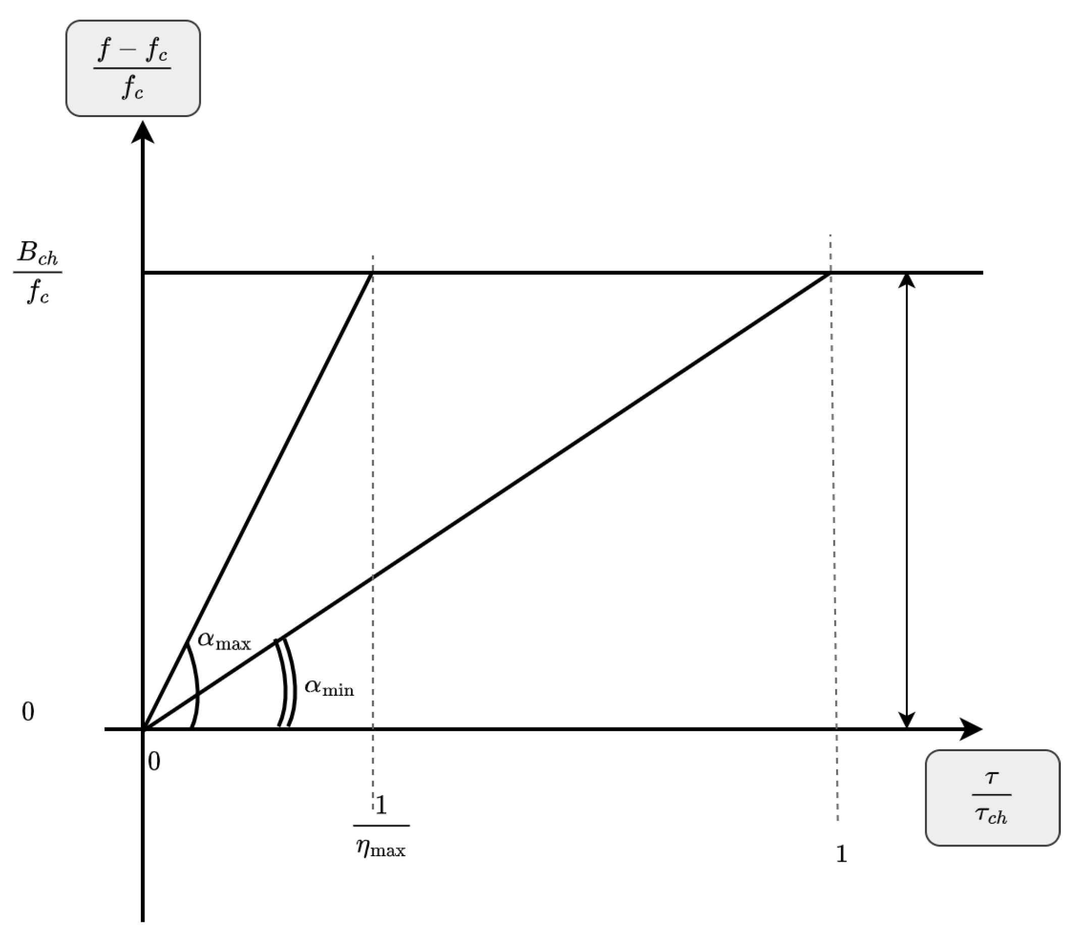
  • Mathematical formulation of the symbol time and the number of overlaps;
  • Deriving the mathematical expression for the bit error probability of the proposed scheme as a function of inter-symbol interference and number of overlaps;
  • Performance evaluation using various metrics to demonstrate the effectiveness of our approach.
The rest of the paper is organized as follows. The DM-CSS is described in more detail in Section 2. Section 3 briefly discusses the M-ary phase shift keying modulation, while Section 4 introduces our contributions. The performance of the system is evaluated in Section 5. The conclusion and future work are presented in Section 6.

2. Direct Modulation CSS

Unlike BOK, in direct modulation CSS, modulation and spreading are performed separately. In the case of high-data-rate transmission, an M-ary coding transforms the input bit sequences into symbols, which are then converted into signals by a modulation scheme such as M-ary phase-shift keying. Finally, DM CSS spreads the modulated signals over the transmission bandwidth. This spreading is done with a single linear up-chirp and aims to increase the signal time from 1 B c h to τ c h [24]. The choice of DM CSS offers the designers the possibility of using any constant-envelope modulation technique to encode the input data. The mathematical representation of a standard chirp waveform is given by Equation (1).
c + ( t ) = a ( t ) exp j θ ( t ) , τ c h 2 t τ c h 2 0 elsewhere
where a ( t ) denotes the data sequence, θ ( t ) is the phase function of the chirp signal, and τ c h is the chirp duration. The instantaneous frequency of the chirp waveform at time t is given by Equation (2).
f ( t ) = 1 2 π d θ d t ( t ) , t [ τ c h 2 , τ c h 2 ] .
The derivative of f ( t ) helps to evaluate the rate of change of the instantaneous frequency of the chirp signal with respect to time t. It is usually called chirp (sweep) rate, and its expression is formulated in Equation (3).
μ ( t ) = d f d t ( t ) = 1 2 π d 2 θ d t 2 ( t ) , t τ c h 2 , τ c h 2 .
In the case of a linear chirp signal, the phase θ ( t ) is a quadratic function. Thus, the instantaneous frequency and its chirp rate are linear and constant, respectively. In what follows, we assume θ ( t ) is given by Equation (4), and f ( t ) is bounded by f max (maximum frequency) and f min (minimum frequency) over the interval τ c h 2 , τ c h 2 .
θ ( t ) = μ π t 2 + 2 π f c t + ϕ i 0 , t τ c h 2 , τ c h 2 ,
μ = f m a x f m i n τ c h ,
where ϕ i 0 is the initial phase of the signal ( ϕ i 0 at t = 0 ), f c is the carrier frequency, and μ , given in Equation (5), is the constant frequency sweep rate.

3. M-Ary Phase Shift Keying

The M-ary techniques are a type of digital modulation scheme used for high-data-rate transmission, where several bits are transmitted at a time rather than one bit. M-ary PSK (MPSK) is a multilevel phase shift keying modulation technique that encodes input signals containing several bits.
The general form of an MPSK modulated signal is given in Equation (6), where { . } denotes the real part, with M = 2 k , ω c = 2 π f c , h τ c h ( t ) is a filter whose pulse response is given in Equation (8), and the random symbols are coded using the values of the phase ϕ m i provided in Equation (9).
s ( t ) = s e ( t ) exp j ω c t , τ c h 2 t τ c h 2
s e ( t ) = 2 E s τ c h i = + h τ c h ( t i τ c h ) exp j ϕ m i ,
h τ c h ( t ) = [ τ c h 2 , τ c h 2 ] ( t ) = 1 if τ c h 2 t τ c h 2 0 elsewhere ,
ϕ m i = m i π M m i 0 , 1 , , M 1
In order to generate more insights from the modulated signal, we apply some trigonometric expansion to Equation (6) to obtain a new signal expression. Equation (10) is the quadrature representation of an MPSK modulated signal, where cos ( ω c t ) and sin ( ω c t ) are the orthogonal carrier signals. This representation leads to a standard method of generating MPSK signals as a linear combination of the quadrature signals cos ( ω c t ) and sin ( ω c t ) . On the horizontal axis of the constellation diagram lies the cosine coefficient (in-phase, or I signal), while the sine coefficient (quadrature or Q signal) is on the vertical axis. The I and Q signals are multiplied by cos ( ω c t ) and sin ( ω c t ) . Then, the MPSK modulated signal is the sum of the mixers’ outputs.
s ( t ) = 2 τ c h i = h τ c h ( t i τ c h ) s m i I cos ( ω c t ) + s m i Q sin ( ω c t ) ,
s m i I = E s cos ( ϕ m i ) , and s m i Q = E s sin ( ϕ m i ) , m i 0 , 1 , , M 1

4. Proposed Model

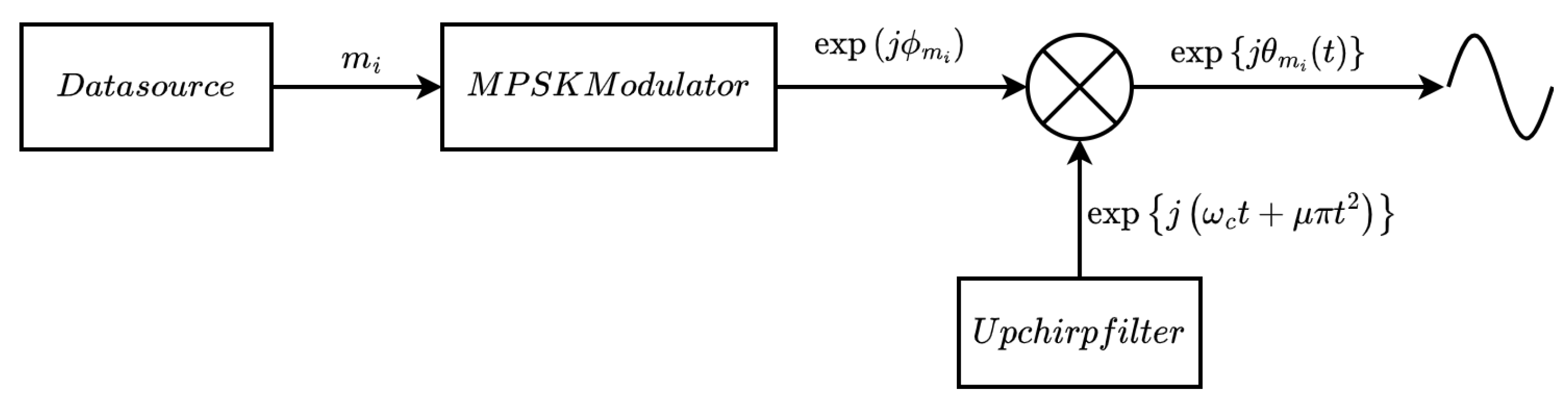
4.1. Modulation Scheme

In this section, we introduce the DM CSS modulated signal. It derives from a general expression of an M-ary chirp modulated signal, which is given in Equation (12), with Equation (13) representing its phase function and E s its energy in the symbol duration τ . It combines the benefits of M-ary Phase Shift Keying (PSK) and those of chirp signalling to provide high-spectral-efficiency transmission. Figure 1 presents the block diagram of the proposed modulation scheme.
MPSK divides and transmits the data stream as a group of k bits ( k N ), called a symbol, with a specific initial phase. The total possible number of symbols is M = 2 k . Each one of the M symbols is transmitted within the timeframe τ c h (we assume that τ τ c h ), which means a total transmission time of N τ c h for N symbols. However, CSS enables transmission of η ( η N , η > 1 ) symbols per τ c h , leading to an overall transmission time of N η τ c h . Therefore, for a given M-ary PSK modulator, we study the maximum number of overlaps at which the intersymbol interference is lower, the mathematical relations between the number of overlaps, the spectral efficiency, and the ISI.
Choosing an M-ary scheme that guarantees a better tradeoff between spectral efficiency and BER performance is also an important design consideration for the proposed DM CSS. The signal model of the proposed MPSK CSS during the chirp duration τ c h is given in Equation (14).
s ( t ) = i = 1 η h τ ( t i τ ) 2 E s τ exp j θ m i ( t ) , τ c h 2 t τ c h 2
θ m i ( t ) = μ π t 2 + ω c t + ϕ m i , m i 0 , 1 , , M 1
s ( t ) = i = 1 η h τ ( t i τ ) s m i I U I ( t ) + s m i Q U Q ( t ) , τ c h 2 t τ c h 2
U I ( t ) = 2 τ cos ω c t + μ π t 2 , τ 2 t τ 2
U Q ( t ) = 2 τ sin ω c t + μ π t 2 , τ 2 t τ 2
In the following section, we establish a relationship between the number of signals that can be overlapped and the number k bits per symbol. This also helps in selecting the ideal MPSK scheme.

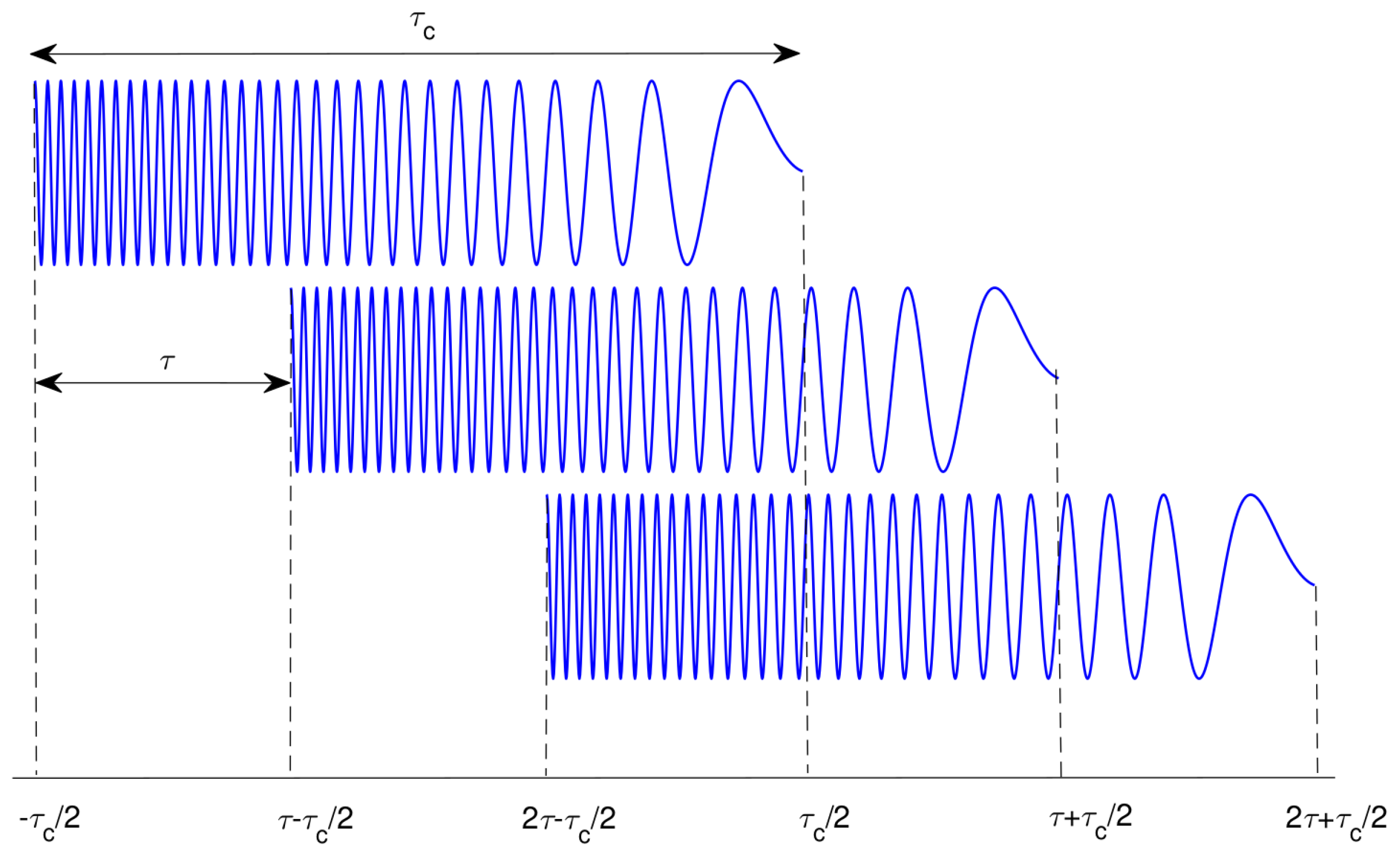
4.2. Overlapping Chirps

DM allows signals to overlap to increase the data rate. The overlap is achieved when the symbol duration τ is less than the chirp duration τ c h . Therefore, the pulse for the next symbol is sent by the transmitter before the signal of the current symbol has fully propagated [24]. The number η of overlapping chirps in a chirp duration is given by Equation (17).
η = τ c h τ
We consider a DM CSS system with fixed bandwidth B c h and chirp duration τ c h . We aim to determine an optimal symbol time τ for which several symbols can be transmitted within a single chirp time without altering the overall system performance. Obviously, the smaller the symbol period, the more signals can be transmitted in a single chirp duration, as illustrated in Figure 2.
However, transmitting many overlapped signals may cause adjacent signals to interfere, thus making detection difficult at the receiver.
To determine the optimal symbol duration τ , we model as a right triangle the time–frequency representation of the instantaneous frequency of a linear chirp. The hypotenuse, opposite side, and adjacent side of the right triangle represent the instantaneous frequency of the chirp signal, the system bandwidth, and the chirp duration, respectively. Figure 3 illustrates a model representation wherein two chirps with symbol durations τ < τ c h and τ = τ c h are displayed. The angle α is inversely proportional to the symbol duration τ and, hence, to the time–bandwidth product B c h τ . Let us denote by α min the value of α at which τ = τ c h , and by α max the value at which τ is the smallest ( τ < < τ c h ). At α = α max , τ becomes smaller such that the area A = 1 2 B c h f c 1 η max of the triangle of Figure 3 is smaller than 1. Since B c h f c < 1 2 (we assume the Nyquist criterion, f c > 2 B c h , is met) and η max > > 1 , chirp signals will overlap in the time frame τ c h .
From Figure 3, we derive η as function of tan α . However, the tangent function tan ( . ) is not defined for α = ( 2 p + 1 ) π 2 with p N and is periodic with a period of π . In addition, the total sum of the angles in the right triangle of Figure 3 is π (or 180 ). This restricts the value of α to 0 < α < π 2 . Given that the bandwidth B c h and chirp duration τ c h are fixed and known, we express in Equations (18) and (19) η and τ as a function of α , where the interval 5 π 34 ; π 2 is an approximation. One can easily observe that η 1 when α = 5 π 34 .
η = f c B c h tan α ,
τ = B c h τ c h f c 1 tan α , 5 π 34 α < π 2

4.3. Inter-Symbol Interference Due to Overlap

Although the overlap technique increases the spectral efficiency, it may cause more inter-symbol interference, leading to serious degradation of BER [21,22,23,25,26]. Therefore, a reasonable tradeoff between spectral efficiency and ISI is required. T. Yoon et al. [23] proposed a theoretical expression for the BER of a CSS overlap system to help choose the optimal number of overlaps. The authors in [21] also proposed a BER expression for a DM CSS system with a finite number of overlaps and investigated the conditions under which the ISI can be minimized while approaching the Nyquist rate. In [22], T. Yoon et al. proposed an explicit expression for ISI due to overlaps in DM CSS with BPSK and discussed the relationship between ISI and the number of overlaps.
The time-shift property of chirp signals helps mitigate inter-symbol interference between successive signals, which are transmitted every τ . DM CSS with MPSK sends each signal Δ τ = τ c h τ before the previous signal evaporates from the filter. In this case, ISI is more likely to occur when Δ τ is larger. We consider transmission over channels with additive white Gaussian noise. The expression of the received signal x ( t ) during the chirp duration τ c h is given in Equation (20). Since DM CSS involves only an up-chirp for spreading, the impulse response of the matched filter at the receiver side is a down-chirp, which is expressed as c ( t ) = exp j ω c t μ π t 2 .
x ( t ) = i = 1 η h τ ( t i τ ) s m i I ( t ) U I ( t ) + s m i Q ( t ) U Q ( t ) + n ( t ) τ c h 2 t τ c h 2
When the received signal passes through the matched filter, the output y ( m τ ) = y s ( m τ ) + y n ( m τ ) , sampled at t = m τ , is obtained. Figure 4 illustrates the signal detection process of the MPSK CSS: y s ( m τ ) is the signal component described by Equation (22), where y e ( m τ ) is the complex envelope of y ( m τ ) , y n = y n e ( m τ ) is the noise component, and Γ = ω c + μ π m τ . For more details on y ( m τ ) , see Appendix A.
y e ( m τ ) = s ( t ) c ( t m τ ) d t y s e ( m τ ) + n ( t ) c ( t m τ ) d t y n e ( m τ )
y s ( m τ ) = y s e ( m τ ) = i = 1 η 2 E s τ exp ( j ϕ m i ) exp j Γ m τ + 2 j Γ i τ exp j τ Γ exp j τ Γ 2 j Γ
y s ( m τ ) = i = 1 η 2 E s τ exp j ϕ m i exp j ( 2 i m ) τ Γ τ s i n c ( τ Γ )
Let y s m i = E s exp j ϕ m i and z i m = 2 τ exp j ( 2 i m ) τ Γ τ s i n c ( τ Γ ) .
y s ( m τ ) = y s m m z 0 + i = 1 , i m η y s m i z i m Λ m ,
where Λ m is the inter-symbol interference due to the overlap of the m-th symbol with the others.

4.4. Zero-ISI Transmission

According to the Nyquist criterion for zero-ISI transmission, z i m = 0 for m > 0 . If this condition is satisfied, the symbol duration should satisfy Equation (25).
i m , z i m = 0 s i n c ( τ Γ ) = 0 ,
sin 2 π f c τ + μ π m τ 2 = sin p π , p N 2 π f c τ + B c h η π m τ = p π
τ = η p 2 f c η + m B c h ,
where the number of overlaps η was formulated in Equation (18).

4.5. Probability of Bit Error

This section provides the theoretical bit error rate derivation. For simplicity and without any loss of generality, we denote the index of the symbol being detected as m. We recall y ( m τ ) = y s m z 0 + Λ m + y n ( m τ ) is the receiver output at time t = m τ , where y n = y n e and y n N ( 0 , N o 2 ) .
We also denote by H m i the hypothesis that the symbol s m i was transmitted and by f ( y | H m i ) the conditional probability density function of y at H m i . The random variable y is Gaussian with mean ( y s m z 0 + Λ m ) and variance N o 2 .
We are interested in finding the bit error probability P b due to an overlap. Let P S E R be the average probability of error for transmitting η overlapped signals. Since the η symbols are equally likely to be sent, then the probability of the symbol s m i being transmitted is P ( H m i ) = 1 η . P ( y | H m i ) is the probability of detecting the right symbol knowing that H m i is true.
P S E R = 1 i = 1 η P ( H m i ) P ( y | H m i )
P ( y | H m i ) = R m i f ( y | R m i ) ,
where R m i is the decision region of the symbol s m i . In [27], it is shown that the average probability P S E R is upper bounded as given in Equation (28):
P S E R i = 1 , m i m η Q d m m i 2 N o ,
where d m m i is the Euclidean distance between s m and s m i and is expressed in Equation (29) (Appendix B.1 provides more details).
d m m i = 2 E s sin 2 ( m m i ) π 2 M
By replacing the expression of d m m i in Equation (28), we obtain in Equation (30) the new expression of the probability P S E R .
P S E R i = 1 , m i m η Q 2 E s N o sin 2 ( m m i ) π 2 M
Finally, an approximation of the average probability of bit error is provided by Equation (31).
P b i = 1 , m i m η 1 2 log 2 ( M ) e r f c 2 log 2 ( M ) E b N o sin 2 ( m m i ) π 2 M

5. Performance Analysis and Discussion

5.1. Simulation Environment

The main parameters of the simulations are the bandwidth B c h = 200 kHz , the chirp duration τ c h = 0 . 05 ms , the total number of symbols M { 4 , 8 , 16 } , and a data stream of 10 5 bits. The simulation was done on MATLAB and under additive white Gaussian noise (AWGN) channels with a stationary transmitter/receiver over the specified bandwidths. The performance metrics considered are the spectral efficiency and the bit error rate.

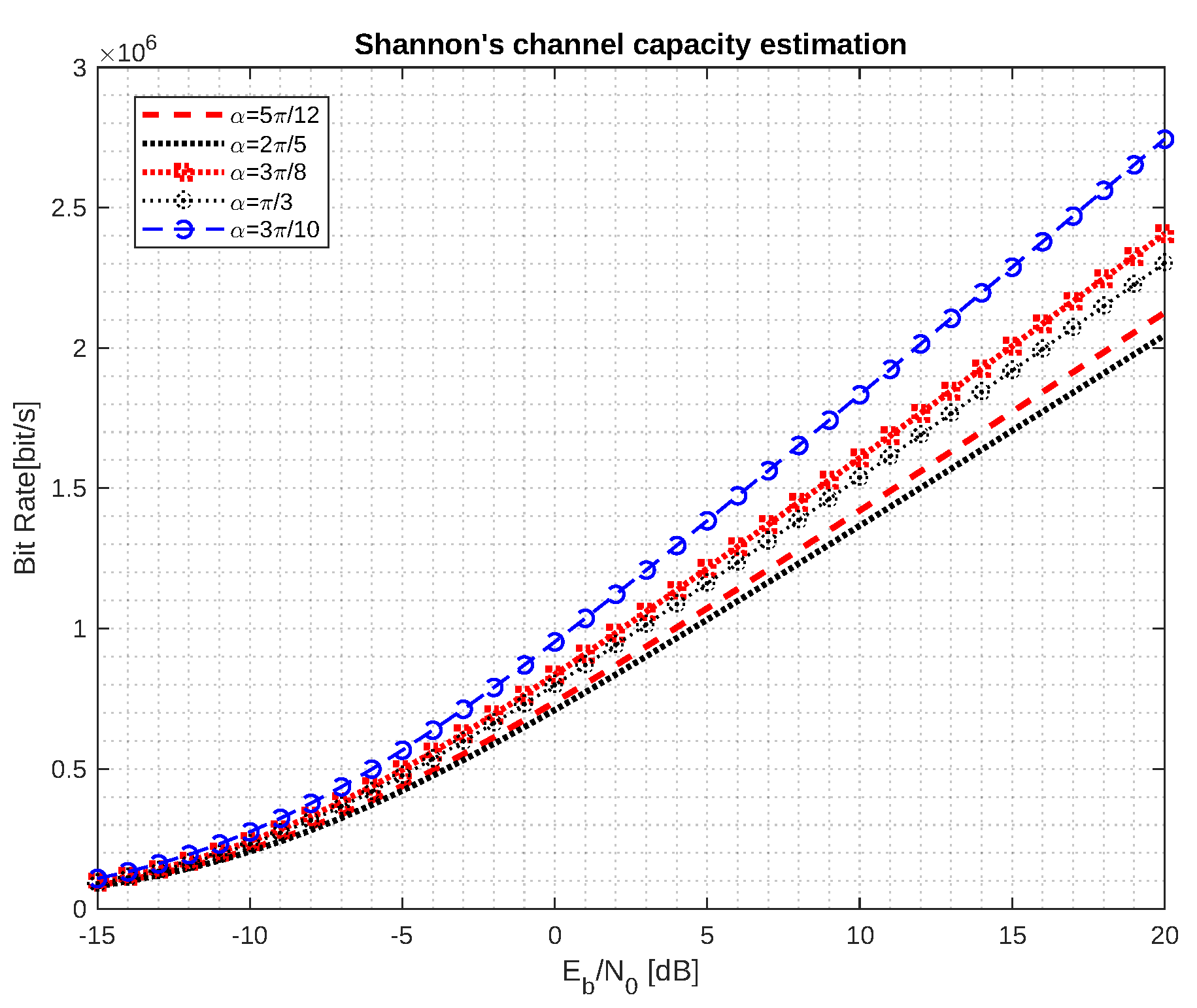
5.2. Spectral Efficiency Analysis

In this paper, we aim to prove that for a given bandwidth B c h and chirp duration τ c h , one can achieve better data rate performance if the symbol duration is set efficiently. The bit rate of an MPSK system is given by R b = log 2 ( M ) τ . Since we consider overlapping transmission, the symbol duration expressed by τ = τ c h η leads to the new theoretical bitrate formulation as in Equation (32).
R b = f c log 2 ( M ) B c h τ c h tan α , 5 π 34 α < π 2
The choice of the symbol duration τ is a function of η . Since τ = τ c h η and τ c h is fixed, the time symbol is inversely proportional to η : τ becomes smaller as η tends to . Therefore, if we suppose there is no interference, the spectral efficiency depends mainly on η , and the larger η is, the higher the spectral efficiency of the system. The values of η in Table 1 are generated from α , based on Equation (18) with f c = 2 B c h . Because in this study the number η of overlaps is an integer, we compute the floor of the real-valued η generated.
Figure 5 illustrates the theoretical bit rates of the system under interference and noise. The plotted results are the Shannon’s channel capacities for some α provided in Table 1. These curves represent the number of correctly detected bits against E b / N 0 for α values in { 3 π 10 , π 3 , 3 π 8 , 2 π 5 , 5 π 12 } . Figure 5 shows that as the angle α increases, the bit rate decreases. At E b / N 0 = 20 , the bit rate of α = 3 π 10 is about 1.5 times more than those of α = 5 π 12 , which is a gap of about 7 Mbit/s. From these results, we conclude that it is preferable not to overlap more than 4 signals.

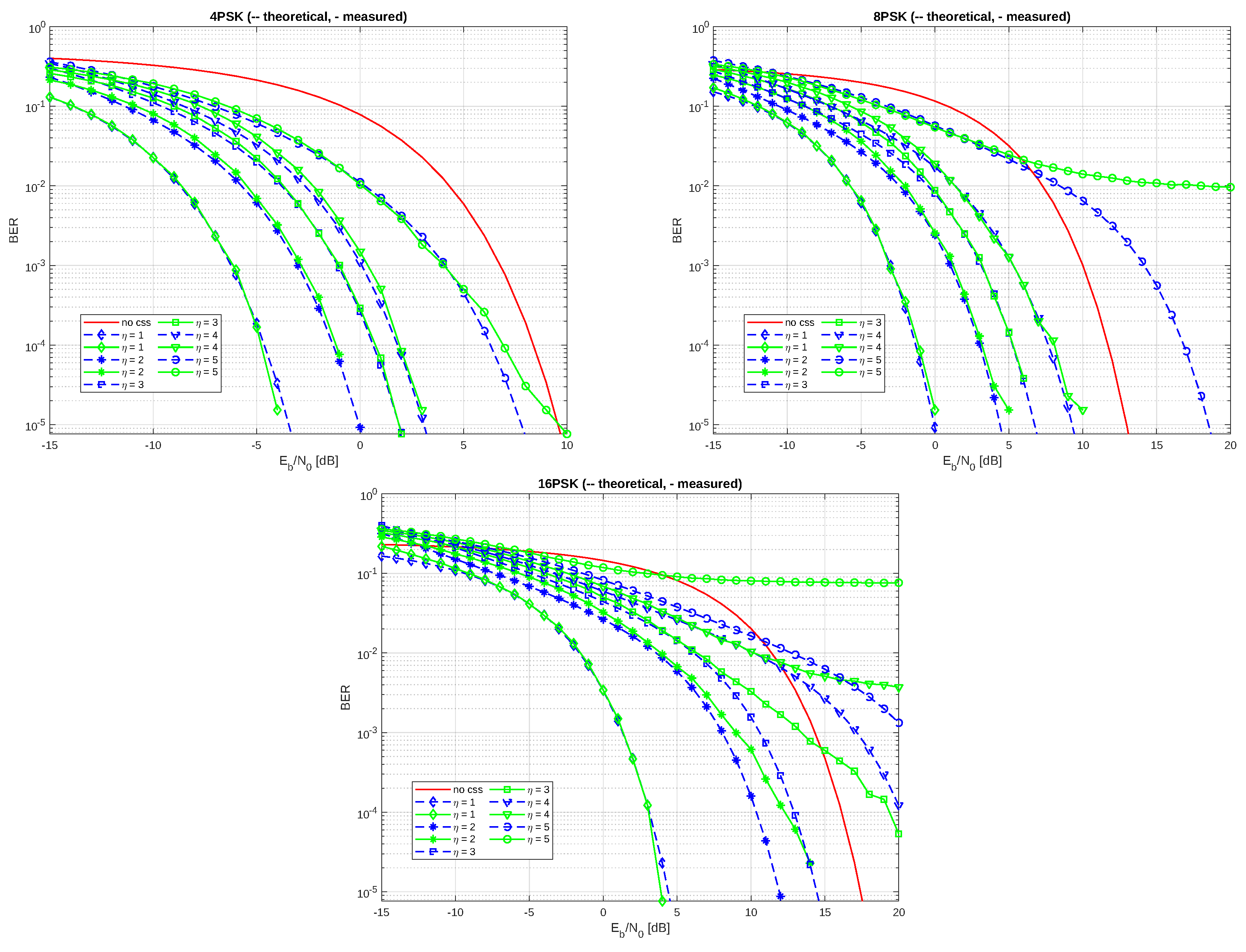
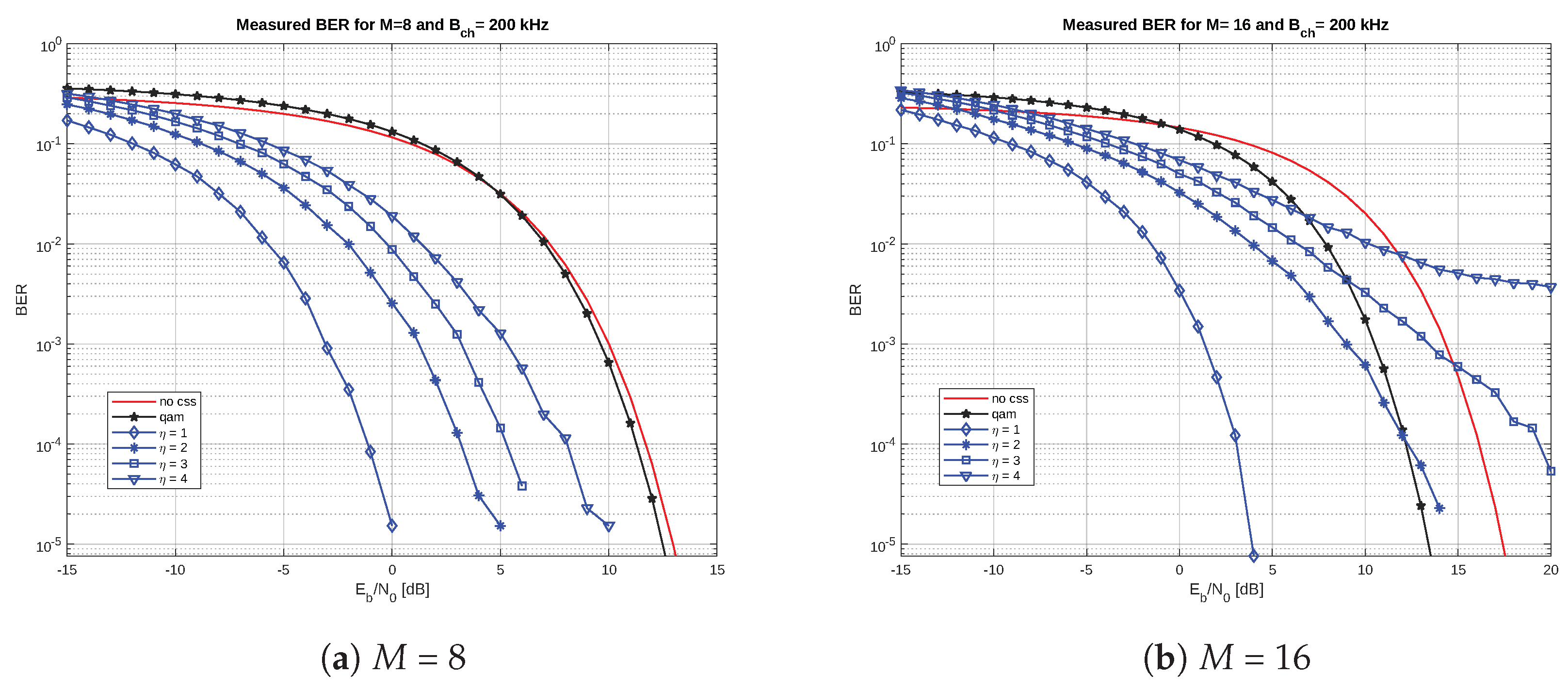
5.3. BER Performance Analysis

The overlap of symbols can lead to inter-symbol interference, which can affect the system performance. Therefore, the effects of interference due to overlapping are taken into account when evaluating the spectral efficiency. The curves of the theoretical bit error, obtained from Equation (31), are plotted against the E b / N 0 in Figure 6 along with the measured values in order to analyse the effects of inter-symbol interference caused by the number of chirp overlaps η . Several values of η (from 1 to 5) are considered, as well as 3 values of M (4, 8, and 16) of the MPSK modulation.
It is worth noting that for a relatively reduced number of overlaps, the theoretical curves fit well with the measured ones, but there are also some discrepancies, especially for higher-order modulations ( M = 16 ). Indeed, although the proposed approach is able to mitigate the effects of inter-symbol interference due to chirp overlaps, as demonstrated in Section 4.4, in practice, the interference is not completely removed due to some signal processing imperfections. Actually, these discrepancies are due to the residual inter-symbol interference, which increases as the number of chirp overlaps and the modulation order increase. The effect of the residual inter-symbol interference is more visible for high signal-to-noise ratios (SNRs), while it is masked by the noise for low SNRs.
Along with the results presented in Section 5.2, the curves in Figure 6 can be used to select an appropriate value for the number of chirp overlaps. Thus, for example, we can conclude that a 16-PSK CSS system with a bandwidth of 200 kHz is likely to achieve higher spectral efficiency and a good tradeoff between BER and bit rate performance when the number of chirps overlapped η { 2 , 3 } .
A comparison of the proposed model with modulation schemes such as the quadrature amplitude modulation (QAM) is also provided in Figure 7.

6. Conclusions

This work arose from the requirement to optimize data transmission as well as to minimize energy consumption in wireless sensor networks. Our previous article [3] addressed the same optimization challenges and proposed a routing protocol based on hypergraph clustering. However, the routing scheme might not be effective if the physical layer of each sensor node comprises a high-bandwidth radio transceiver, such as 5G.
Therefore, in this work, we combined M-ary phase shift keying and chirp spread spectrum modulation techniques to develop bandwidth-efficient modulation for wireless sensors networks. MPSK modulation enables the transmission of log 2 ( M ) bits per symbol, while CSS helps transmit η symbols in a single chirp time τ c h . The time–frequency representation of the instantaneous frequency of a chirp, along with some mathematical properties, are used to model the time symbol τ and the number η of overlaps as a function of a non-right angle α . We derived the expression BER as a function of η to analyse and mitigate the effects of inter-symbol interference due to overlaps. We evaluated the proposed model in terms of spectral efficiency and bit error probability. Simulation results showed that the best system performance, in terms of tradeoff between the bit rate and BER, is achieved when 2 η 3 for a 16-PSK CSS with a 200 kHz-bandwidth. As future work, we plan to develop a standard mathematical formulation of the optimal number η of overlaps for a given bandwidth B c h , chirp time τ c h , number of symbols M, signal-to-noise E b / N 0 , and data stream size. We also plan to take into account user mobility and study its impact on the system’s BER.

Author Contributions

Conceptualization, J.E.Z.G.; Methodology, J.E.Z.G., A.A.A.A. and A.M.G.; Software, J.E.Z.G. and E.R.; Validation, A.A.A.A., E.R. and A.M.G.; Formal analysis, A.A.A.A. and E.R.; Investigation, J.E.Z.G., A.A.A.A. and E.R.; Resources, J.E.Z.G.; Data curation, J.E.Z.G.; Writing—original draft, J.E.Z.G.; Writing—review & editing, A.A.A.A., E.R. and A.M.G.; Supervision, A.A.A.A., E.R. and A.M.G.; Project administration, E.R.; Funding acquisition, J.E.Z.G. All authors have read and agreed to the published version of the manuscript.

Funding

This research received no external funding.

Institutional Review Board Statement

Not applicable.

Informed Consent Statement

Not applicable.

Data Availability Statement

Not applicable.

Acknowledgments

The authors would like to thank the editor and the anonymous reviewers for their useful and valuable remarks, which helped us to improve the content and presentation of the paper. This work is partially supported by the Agence Universitaire de la Francophonie (AUF) under the Collège Doctoral Régional MATHINBIO program.

Conflicts of Interest

The authors declare no conflict of interest.

Abbreviations

The following abbreviations are used in this manuscript:
AWGNAdditive White Gaussian Noise
BERBit Error Rate
BOCBinary Offset Carrier
BOKBinary Orthogonal Keying
CCCCross Correlation Coefficients
CSSChirp Spread Spectrum
DM CSSDirect Modulation Chirp Spread Spectrum
ISIInter-Symbol Interference
MPSKM-ary Phase Shift Keying

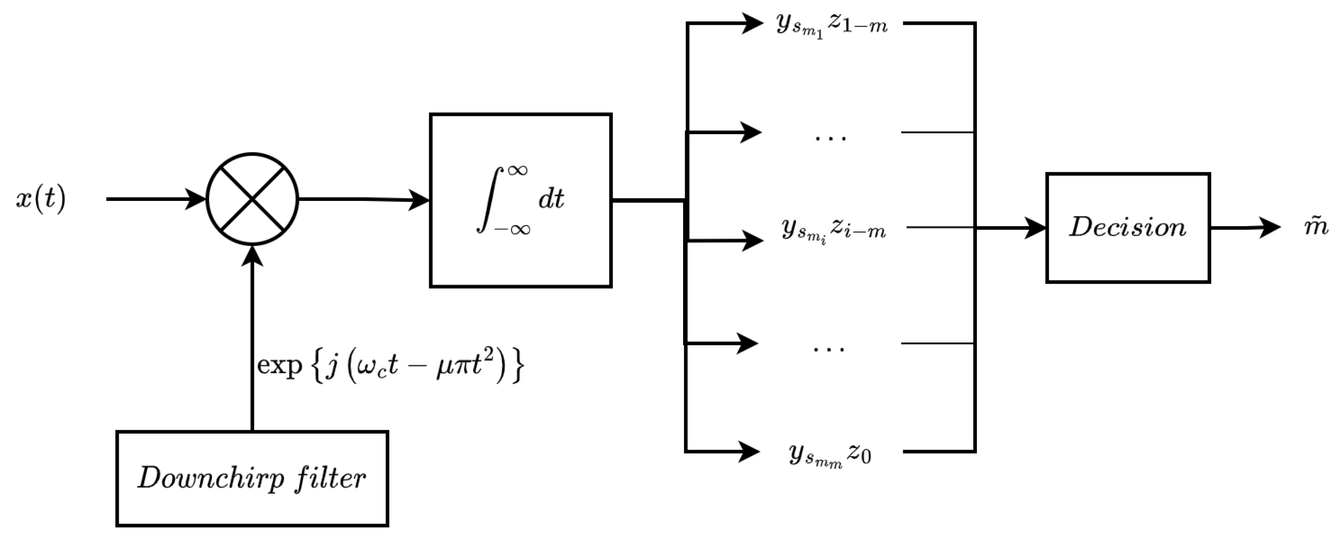
Appendix A. Expression of the Receiver Output

The signal of interest at the input of the matched filter during the chirp duration τ c can be expressed as:
s ( t ) = l = 1 η c 2 E s τ h τ ( t l τ ) exp j ϕ i exp j ω c t + μ π t 2
Consequently, the signal at the receiver output at t = m τ is given by:
y e ( m τ ) = s ( t ) c ( t m τ ) d t + n ( t ) c ( t m τ ) d t = l = 1 η c h τ ( t l τ ) s i ( t ) c ( t m τ ) d t y s e ( m τ ) + n ( t ) c ( t m τ ) d t
Let us now develop the first term of (A2):
y s e ( m τ ) = l = 1 η c h τ ( t l τ ) s i ( t ) exp j ( ω c ( t m τ ) μ π ( t m τ ) 2 ) d t = l = 1 η c 2 E s τ h τ ( t l τ ) exp ( j ϕ i ) exp 2 ω c t + 2 μ π m τ t ω c m τ μ π m 2 τ 2 = l = 1 η c 2 E s τ exp j ϕ i exp j Γ m τ h τ ( t l τ ) exp 2 j Γ t d t
with Γ = ω c + μ π m τ , and h τ ( t l τ ) = 1 if l τ τ 2 t l τ + τ 2 0 elsewhere .
Thus, we further obtain:
y s e ( m τ ) = l = 1 η c 2 E s τ exp ( j ϕ i ) exp j Γ m τ exp 2 j Γ l τ exp j τ Γ exp j τ Γ 2 j Γ = l = 1 η c 2 E s τ exp ( j ϕ i ) exp j ( 2 l m ) Γ τ τ s i n c τ Γ
Let y s i = 2 E s τ exp j ϕ i and z l m = exp j ( 2 j m ) τ Γ τ s i n c τ Γ . We finally obtain:
y s e ( m τ ) = y s m m z 0 + l = 1 , i m η c y s i z i m

Appendix B. Probability of Bit Error

Appendix B.1. Euclidean Distance between sm and ssmi

The Euclidean distance between s m ( E s cos ( ϕ m ) , E s sin ( ϕ m ) ) and s m i ( E s cos ( ϕ m i ) , E s sin ( ϕ m i ) ) is:
d m m i = E s cos ( ϕ m ) E s cos ( ϕ m i ) 2 + E s sin ( ϕ m ) + E s sin ( ϕ m i ) 2
Simplifying this expression, we obtain:
d m m i = E s c o s ( ϕ m ) cos ( ϕ m i ) 2 + E s sin ( ϕ m ) + sin ( ϕ m i ) 2 = E s ( cos 2 ( ϕ m i ) + sin 2 ( ϕ m i ) + cos 2 ( ϕ m ) + sin 2 ( ϕ m ) ) + E s ( 2 cos ( ϕ m ) cos ( ϕ m i ) 2 sin ( ϕ m ) sin ( ϕ m i ) ) = E s ( 2 2 cos ( ϕ m ) cos ( ϕ m i ) 2 sin ( ϕ m ) sin ( ϕ m i ) ) = 2 E s ( 1 cos ( ϕ m ) cos ( ϕ m i ) sin ( ϕ m ) sin ( ϕ m i ) ) = 2 E s ( 1 cos ( m π M m i π M ) )
Therefore, the Euclidean distance between s m and s m i is:
d m m i = 2 E s sin 2 ( ( m m i ) π 2 M )

References

  1. Pickholtz, R.; Schilling, D.; Milstein, L. Theory of spread-spectrum communications-a tutorial. IEEE Trans. Commun. 1982, 30, 855–884. [Google Scholar] [CrossRef] [Green Version]
  2. Springer, A.; Gugler, W.; Huemer, M.; Reindl, L.; Ruppel, C.; Weigel, R. Spread spectrum communications using chirp signals. In Proceedings of the IEEE/AFCEA EUROCOMM 2000. Information Systems for Enhanced Public Safety and Security (Cat. No. 00EX405), Munich, Germany, 19 May 2000; IEEE: Piscataway, NJ, USA, 2000; pp. 166–170. [Google Scholar]
  3. Gbadouissa, J.E.Z.; Ari, A.A.A.; Titouna, C.; Gueroui, A.M.; Thiare, O. HGC: HyperGraph based Clustering scheme for power aware wireless sensor networks. Future Gener. Comput. Syst. 2020, 105, 175–183. [Google Scholar] [CrossRef]
  4. Ari, A.A.A.; Labraoui, N.; Yenké, B.O.; Gueroui, A. Clustering algorithm for wireless sensor networks: The honeybee swarms nest-sites selection process based approach. Int. J. Sens. Netw. 2018, 27, 1–13. [Google Scholar] [CrossRef]
  5. Dixon, R. Why spread spectrum? Commun. Soc. 1975, 13, 21–25. [Google Scholar] [CrossRef]
  6. Torrieri, D. Principles of Spread-Spectrum Communication Systems; Springer: Berlin/Heidelberg, Germany, 2005; Volume 1. [Google Scholar]
  7. Aydin, N.; Arslan, T.; Cumming, D.R. A direct-sequence spread-spectrum communication system for integrated sensor microsystems. IEEE Trans. Inf. Technol. Biomed. 2005, 9, 4–12. [Google Scholar] [CrossRef] [PubMed]
  8. Hengstler, S.; Kasilingam, D.P.; Costa, A.H. A novel chirp modulation spread spectrum technique for multiple access. In Proceedings of the IEEE Seventh International Symposium on Spread Spectrum Techniques and Applications, Prague, Czech Republic, 2–5 September 2002; IEEE: Piscataway, NJ, USA, 2002; Volume 1, pp. 73–77. [Google Scholar]
  9. Ouyang, X.; Dobre, O.A.; Guan, Y.L.; Zhao, J. Chirp spread spectrum toward the Nyquist signaling rate—Orthogonality condition and applications. IEEE Signal Process. Lett. 2017, 24, 1488–1492. [Google Scholar] [CrossRef]
  10. Kim, K.Y.; Lee, S.W.; Shin, Y. Spectral Efficiency Improvement of Chirp Spread Spectrum Systems. In Proceedings of the 2019 International Conference on Information and Communication Technology Convergence (ICTC), Jeju, Republic of Korea, 16–18 October 2019. [Google Scholar]
  11. Qiu, S.; Zhao, D.; Wang, Y.; Tang, X.; Zhao, X.; Zhang, Y. A Linear Chirp Wireless Transmission Method utilizing Doppler Effect. Wirel. Pers. Commun. 2022, 124, 2965–2982. [Google Scholar] [CrossRef]
  12. Nguyen, T.T.; Nguyen, H.H.; Barton, R.; Grossetete, P. Efficient Design of Chirp Spread Spectrum Modulation for Low-Power Wide-Area Networks. IEEE Internet Things J. 2019, 6, 9503–9515. [Google Scholar] [CrossRef]
  13. Hosseini, N.; Matolak, D.W. Chirp Spread Spectrum Signaling for Future Air-Ground Communications. In Proceedings of the MILCOM 2019-2019 IEEE Military Communications Conference (MILCOM), Norfolk, VA, USA, 12–14 November 2019; IEEE: Piscataway, NJ, USA, 2019; pp. 153–158. [Google Scholar]
  14. Yang, Y.; Zhang, Y.; Dai, L.; Li, J.; Mumtaz, S.; Rodriguez, J. Transmission capacity analysis of relay-assisted device-to-device overlay/underlay communication. IEEE Trans. Ind. Inform. 2016, 13, 380–389. [Google Scholar] [CrossRef]
  15. Pohl, A.; Ostermayer, G.; Steindl, R.; Seifert, F.; Weigel, R. Fine tuning of data rate enhances performance of a chirp spread spectrum system. In Proceedings of the 1998 IEEE 5th International Symposium on Spread Spectrum Techniques and Applications-Proceedings. Spread Technology to Africa (Cat. No. 98TH8333), Sun City, South Africa, 4 September 1998; IEEE: Piscataway, NJ, USA, 1998; Volume 1, pp. 78–81. [Google Scholar]
  16. Kim, K.Y.; Shin, Y. Simultaneous Orthogonal Transmission for Direct Modulation Chirp Spread Spectrum Systems. In Proceedings of the 2019 Eleventh International Conference on Ubiquitous and Future Networks (ICUFN), Zagreb, Croatia, 2–5 July 2019; IEEE: Piscataway, NJ, USA, 2019; pp. 472–474. [Google Scholar]
  17. Reynders, B.; Pollin, S. Chirp spread spectrum as a modulation technique for long range communication. In Proceedings of the 2016 Symposium on Communications and Vehicular Technologies (SCVT), Mons, Belgium, 22 November 2016; IEEE: Piscataway, NJ, USA, 2016; pp. 1–5. [Google Scholar]
  18. Cai, C.; Chen, Z.; Luo, J.; Pu, H.; Hu, M.; Zheng, R. Boosting chirp signal based aerial acoustic communication under dynamic channel conditions. IEEE Trans. Mob. Comput. 2021, 21, 3110–3121. [Google Scholar] [CrossRef]
  19. Araújo, D.C.; Ferré, G.; Cavalcante, C.C.; Guerreiro, I.M. A Spectral Efficiency Enhancement for Chirp Spread Spectrum Downlink Communications. In Proceedings of the 2020 IEEE Latin-American Conference on Communications (LATINCOM), Santo Domingo, Dominican Republic, 18–20 November 2020; IEEE: Piscataway, NJ, USA, 2020; pp. 1–6. [Google Scholar]
  20. Azim, A.W.; Bazzi, A.; Shubair, R.; Chafii, M. Dual-Mode Chirp Spread Spectrum Modulation. arXiv 2022, arXiv:2205.09421. [Google Scholar] [CrossRef]
  21. Pham, T.M.; Barreto, A.N.; Fettweis, G.P. Efficient Communications for Overlapped Chirp-Based Systems. IEEE Wirel. Commun. Lett. 2020, 9, 2202–2206. [Google Scholar] [CrossRef]
  22. Yoon, T.; Lee, Y.; Park, S.R.; Kim, S.C.; Song, I.; Yoon, S. Analysis of Intersymbol Interference due to Overlap in DM-BPSK. IEICE Trans. Commun. 2010, 93, 1310–1312. [Google Scholar] [CrossRef]
  23. Yoon, T.; Yoo, S.H.; Kim, S.Y.; Yoon, S. A Closed Form BER expression for an Overlap-based CSS System. In Proceedings of the ITC-CSCC: International Technical Conference on Circuits Systems, Computers and Communications, Shimonoseki City, Japan, 6–9 July 2008; pp. 105–108. [Google Scholar]
  24. Pinkney, J. Low Complexity Indoor Wireless Data Links Using Chirp Spread Spectrum. Ph.D. Thesis, University of Calgary, Calgary, AB, Canada, 2004. [Google Scholar]
  25. Mumtaz, S.; Huq, K.M.S.; Radwan, A.; Rodriguez, J.; Aguiar, R.L. Energy efficient interference-aware resource allocation in LTE-D2D communication. In Proceedings of the 2014 IEEE International Conference on Communications (ICC), Sydney, NSW, Australia, 10–14 June 2014; IEEE: Piscataway, NJ, USA, 2014; pp. 282–287. [Google Scholar]
  26. Yang, Q.; Jiang, T.; Beaulieu, N.C.; Wang, J.; Jiang, C.; Mumtaz, S.; Zhou, Z. Heterogeneous semi-blind interference alignment in finite-SNR networks with fairness consideration. IEEE Trans. Wirel. Commun. 2020, 19, 2472–2488. [Google Scholar] [CrossRef]
  27. Grami, A. Passband Digital Transmission; Academic Press: Cambridge, MA, USA, 2015; Chapter 7; pp. 299–355. [Google Scholar]
Figure 1. Block diagram describing the proposed MPSK CSS modulation scheme.
Information 14 00323 g001
Figure 2. Illustration of overlapping transmission with the number of overlapped signals η = 3 .
Information 14 00323 g002
Figure 3. Time–frequency representation of the instantaneous frequency of up-chirp signals with normalized time and frequency axes.
Information 14 00323 g003
Figure 4. Block diagram illustrating the MPSK CSS detection process.
Information 14 00323 g004
Figure 5. Comparison of Shannon’s channel capacity as function of E b / N 0 and α .
Information 14 00323 g005
Figure 6. Theoretical and measured BER as a function of E b / N 0 for MPSK CSS with B c h = 200 kHz.
Information 14 00323 g006
Figure 7. Measured BER as a function of E b / N 0 for PSK, QAM, and PSK CSS with η { 2 , 3 , 4 } .
Information 14 00323 g007
Table 1. Number η of overlaps as function of α when f c B c h = 2 .
α π 6 π 5 π 4 3 π 10 π 3 3 π 8 2 π 5 5 π 12
tan α 3 3 5 2 5 1 25 + 10 5 5 3 2 + 1 5 + 2 5 2 + 3
η 1.1547 1.4531 2.0 2.7528 3.4641 4.8284 6.1554 7.4641
η 11223467
Disclaimer/Publisher’s Note: The statements, opinions and data contained in all publications are solely those of the individual author(s) and contributor(s) and not of MDPI and/or the editor(s). MDPI and/or the editor(s) disclaim responsibility for any injury to people or property resulting from any ideas, methods, instructions or products referred to in the content.

