Article

METRIC—Multi-Eye to Robot Indoor Calibration Dataset

Departement of Information Engineering, University of Padova, Via Giovanni Gradenigo 6b, 35131 Padova, Italy
*
Author to whom correspondence should be addressed.
Information 2023, 14(6), 314; https://doi.org/10.3390/info14060314
Submission received: 14 April 2023 / Revised: 18 May 2023 / Accepted: 24 May 2023 / Published: 29 May 2023
(This article belongs to the Special Issue Computer Vision, Pattern Recognition and Machine Learning in Italy)

Abstract

:
Multi-camera systems are an effective solution for perceiving large areas or complex scenarios with many occlusions. In such a setup, an accurate camera network calibration is crucial in order to localize scene elements with respect to a single reference frame shared by all the viewpoints of the network. This is particularly important in applications such as object detection and people tracking. Multi-camera calibration is a critical requirement also in several robotics scenarios, particularly those involving a robotic workcell equipped with a manipulator surrounded by multiple sensors. Within this scenario, the robot-world hand-eye calibration is an additional crucial element for determining the exact position of each camera with respect to the robot, in order to provide information about the surrounding workspace directly to the manipulator. Despite the importance of the calibration process in the two scenarios outlined above, namely (i) a camera network, and (ii) a camera network with a robot, there is a lack of standard datasets available in the literature to evaluate and compare calibration methods. Moreover they are usually treated separately and tested on dedicated setups. In this paper, we propose a general standard dataset acquired in a robotic workcell where calibration methods can be evaluated in two use cases: camera network calibration and robot-world hand-eye calibration. The Multi-Eye To Robot Indoor Calibration (METRIC) dataset consists of over 10,000 synthetic and real images of ChAruCo and checkerboard patterns, each one rigidly attached to the robot end-effector, which was moved in front of four cameras surrounding the manipulator from different viewpoints during the image acquisition. The real images in the dataset includes several multi-view image sets captured by three different types of sensor networks: Microsoft Kinect V2, Intel RealSense Depth D455 and Intel RealSense Lidar L515, to evaluate their advantages and disadvantages for calibration. Furthermore, in order to accurately analyze the effect of camera-robot distance on calibration, we acquired a comprehensive synthetic dataset, with related ground truth, with three different camera network setups corresponding to three levels of calibration difficulty depending on the cell size. An additional contribution of this work is to provide a comprehensive evaluation of state-of-the-art calibration methods using our dataset, highlighting their strengths and weaknesses, in order to outline two benchmarks for the two aforementioned use cases.

1. Introduction

The use of camera networks has become increasingly popular in various computer vision applications, such as human pose estimation, 3D object detection and 3D reconstruction [1,2,3,4]. Multi-camera systems offer the advantage of monitoring larger areas and making several computer vision algorithms more robust against occlusion problems. These challenges frequently occur in complex real-world scenarios such as people tracking applications [5] or robotic workcells [6].
Calibrating a camera network is a crucial step in setups involving multiple cameras, and it typically involves determining intrinsic and extrinsic parameters. Intrinsic calibration is necessary to determine the internal sensor parameters required to accurately project the scene from each 3D camera reference frame onto the corresponding 2D image plane, and they can be obtained using algorithms such as Zhang’s or Sturm’s [7,8]. Extrinsic calibration is required to establish a single 3D reference frame shared by all sensors in the camera network, which is essential for multi-camera applications, since it allows the accurate localization of objects or people in the scene with respect to this common reference system. Both intrinsic and the extrinsic calibration involve an image acquisition phase where a calibration pattern is placed in different positions and orientations in front of the sensors. By detecting the pattern control points, an optimization process is performed to estimate camera parameters, which may involve, for example, minimizing the reprojection error [9]. This step is necessary to accurately determine the camera’s intrinsic and extrinsic parameters. The calibration pattern can be either a planar model, such as checkerboard or the ChAruCo pattern [10], or any other object whose shape is known and is showing elements that are easily recognizable [11]. Intrinsic parameters require calibration pattern images taken at short distances from the sensor in order to cover the entire image plane, whereas extrinsic calibration is often performed by keeping the calibration pattern at longer distances to ensure, for example, its simultaneous detection by multiple cameras. Hence, the two calibration processes are typically performed in two separate steps. Furthermore, intrinsic calibration is conducted separately for each sensor, and intrinsic parameters such as focal length and image center are occasionally provided by the sensor manufacturer; therefore, cameras are sometimes considered to be intrinsically calibrated. For this reason, the term camera network calibration will be used in this paper to refer specifically to extrinsic camera calibration.
Camera network calibration is required for several applications, including multi-camera navigation systems [12], people-tracking within camera networks [13], and surveillance systems [14]. Camera network calibration is also critical in robotic scenarios [15,16], especially when dealing with a robotic workcell composed of a robot arm surrounded by a camera network installed to monitor the workcell area [5,17,18]. In such cases, it is essential to provide the robot with accurate information about its working environment. Simply estimating the relative positions among the cameras is not enough. The single reference frame shared by all viewpoints is required, which may be an external world reference frame or, more commonly, it may coincide with the robot’s base. Defining the reference frame coincident with the robot’s base allows the robot to locate an object of interest with respect to itself for several tasks, such as industrial and medical applications [19,20]. In this context, robot-world hand-eye calibration is essential since it is necessary to determine the exact position of the manipulator with respect to each external camera observing it. This process can be performed using measurements of specific control points (e.g., AprilTags) in the room with known coordinates with respect to the reference frame of the robot’s base or by using targets such as circles or spheres [21]. However, it typically involves an optimization procedure that leverages the corner detection of a planar calibration pattern that is attached to the robot’s end effector and moved in different positions in front of the sensors. The calibration of a camera network with a robot poses many additional challenges with respect to the common calibration procedure of camera networks: (i) the usage of a limited-size calibration pattern due to the need to move the robot without self-collisions; (ii) large distance of the cameras from the robot to monitor a wider area (i.e., the entire workcell). Considering these challenges, in this paper we will address the calibration of a camera network in a real-world scenario, such as the multi-camera setup of a robotic workcell.
Many researchers tackle the problem of camera network calibration, but only a few datasets are available in the literature to evaluate different calibration methods in challenging real-world scenarios with large distances among cameras. Tabb et al. [22] released synthetic and real datasets to calibrate camera networks using a ChAruCo pattern. The calibration process involved manually moving the model in front of the sensors at a short distance. In [23], Wang and Jang presented a similar dataset for calibrating a camera network. The dataset was acquired by manually moving a checkerboard in front of a multi-camera system at a distance of approximately 1 meter. Tabb et al. [24] published a dataset consisting of both synthetic and real data that can be used to evaluate different multiple hand-eye calibration methods. The authors captured several images of a checkerboard by moving a robot arm with a multi-camera system attached to its end-effector in different positions in front of the calibration pattern approximately one meter away from the sensor. The main problem with the first two datasets is that they were acquired by manually moving the calibration pattern in front of the sensors. If the human operator is not able to keep the calibration pattern still, then the manual movement is not guaranteed to collect sharp and clear images during the acquisition phase, negatively affecting the corner detection and consequently compromising the accuracy of the calibration results. Moreover, all datasets consist of a sequence of images of the calibration pattern positioned fairly close to the sensors in a small robotic workcell, making it impossible to test the robustness of different calibration methods and their applicability to larger areas, such as a robotic workcell, where it a wide camera network is required. Furthermore, the few calibration datasets available are tailored to the specific needs of the authors for their experiments. For instance, some datasets are designed exclusively for camera network calibration [22,23], neglecting any robot-related issues since the robot arm is not necessary for the experiments; other datasets are focused on robot-world hand-eye calibration [24], ignoring camera network considerations because there is only one camera and it is attached to the robot’s end-effector. As a result, various calibration methods are often evaluated on different configurations and tailored to specific tasks, making it difficult to compare their performance.
The first contribution of this paper is the proposal of a novel dataset (https://doi.org/10.5281/zenodo.7976058, accessed on 1 April 2023) acquired in a robotic workcell where state-of-the-art calibration methods can be evaluated under various challenging conditions, such as large distances between cameras and the robot and the use of small calibration patterns. In such a challenging scenario, two relevant use cases were considered:
  • Camera network calibration;
  • Robot-world hand-eye calibration.
The dataset was acquired in a robotic workcell equipped with a robot arm with a small calibration pattern rigidly attached to its end-effector. The pattern was moved by means of the manipulator in several positions and orientations in front of the surrounding cameras in order to acquire several images of the pattern, thus avoiding accidental movements of the calibration pattern during the image acquisition. The dataset consists of two main categories: the synthetic images and the real images. The synthetic images were collected in a simulated robotic workcell with different workcell sizes, allowing for the evaluation of the accuracy and robustness of the different state-of-the-art calibration algorithms at increasing distances between sensors and the robot, in ideal lighting conditions, by comparing their results with the ground truth provided by the simulator. On the other hand, the real dataset focuses on the image acquisition on a real robotic workcell with camera networks equipped with different types of sensors. This part of the dataset aims to evaluate the robustness of different cameras on real-world images, which can be blurred, negatively affecting the corner detection and, consequently, the final calibration results.
The second significant contribution of the paper is the proposal of two benchmarks for the two outlined use cases for evaluating and testing calibration methods on the proposed dataset. The benchmark for the camera network calibration use case evaluates calibration methods by measuring the accuracy of the estimated geometric transformations between sensors within the camera network. In contrast, the benchmark for the robot-world hand-eye calibration evaluates the calibration process by assessing the accuracy of the estimated geometric transformation between each camera and the robot base. Overall, the proposed benchmarks and dataset provide a comprehensive framework for evaluating and comparing calibration methods in a real-world and complex scenario. This can involve ideal situations where calibration pattern is easily detectable because the sensors are placed closer to the robot arm. On the other hand, it can require a larger camera network to monitor a larger scene, with a sufficiently compact calibration pattern to facilitate robot motions, resulting in a more challenging calibration process.
The remainder of this paper is organized as follows. Section 2 reviews some state-of-the-art camera network calibration methods and robot-world hand-eye calibration techniques and the datasets designed for camera network or robot-world hand-eye calibration. Section 3 describes in detail the methodology used to acquire the synthetic and real datasets, as well as their functionalities. Additionally, Section 4 provides a more specific description of the dataset structure. In Section 5, we present a comprehensive evaluation of the state-of-the-art calibration methods discussed in Section 2, which have provided the code, according to the two benchmarks for the two use cases mentioned. Finally, in Section 6, conclusions and future works are described.

2. Related Works

Several methods have been proposed in the literature targeting camera network calibration and robot-world hand-eye calibration, and in both use cases, a planar calibration pattern such as ChAruCo and checkerboard is typically used. However, these algorithms have been typically evaluated on dedicated setups and specific datasets, limiting the comparison among different methods. Currently, there is a lack of general datasets that can be used to evaluate the performance of calibration algorithms and test their robustness under different conditions, such as variations in the distance between the camera and the calibration pattern.

2.1. Camera Network Calibration

Some of the camera network calibration techniques that share a common approach by using planar calibration patterns are described in more detail below.
Kim et al. [12] proposed an extrinsic calibration process of multi-camera systems composed by lidar-camera combinations for navigation systems. The proposed method used a planar checkerboard pattern, which was manually moved in front of the sensors during the calibration process. Furgale et al. [25] proposed Kalibr, a novel framework that employs maximum-likelihood estimation to jointly calibrate temporal offsets and geometric transformations of multiple sensors. The robustness of the approach is demonstrated through an extensive set of experiments, including the calibration of a camera and an inertial measurement unit (IMU). Tabb et al. [22], proposed a method for calibrating asynchronous camera networks. The method addresses the calibration of multi-camera systems without relying on the hardware or the synchronization level among cameras, which is typically a main factor strongly influencing camera network calibration results. Caron et al. [26] introduced an algorithm for the simultaneous intrinsic and extrinsic calibration of a multi-camera system using different models for each camera. The algorithm is based on minimizing the corner reprojection error computed on each camera using the corresponding projection model for each sensor, and they exploit a set of images of a calibration pattern, such as a checkerboard, manually moved at different distances and different positions in front of the cameras. Munaro et al. presented OpenPTrack, an open-source multi-camera calibration software designed for people-tracking in RGB-D camera networks [13]. They proposed a camera network calibration system that works on images acquired from all the sensors while manually moving a checkerboard within the tracking space to allow more than one camera to detect it, followed by a global optimization of the camera and checkerboard poses. All of the above methods address the calibration of specific camera network configurations using a checkerboard or a ChAruCo pattern, but they have been tested on their respective datasets for specific tasks, which may limit the comparability of different techniques using a general dataset.

2.2. Robot-World Hand-Eye Calibration

Several works in the literature have addressed the issue of robot-world hand-eye calibration, adopting planar calibration patterns. In a previous study [27], we proposed a non-linear optimization algorithm to solve the robot-world hand-eye calibration problem with a single camera. The proposed method involved the minimization of the corner reprojection error of a checkerboard that was rigidly attached to the robot’s end-effector and moved in front of the sensor at different positions and orientations during the image acquisition. In a scenario where a robot is surrounded by a camera network consisting of N sensors, this method must be applied N times, one for each sensor, to determine the pose of each camera with respect to the robot and thus to calculate the relative pose between the different cameras. Tabb et al. [24] proposed a robot-world hand-multiple-eye calibration procedure using a classic checkerboard and compared two main techniques, each based on a different cost function. The first cost function minimizes the difference of two transformation chains over n positions of the robot arm achieved during the image acquisition, and it is based on the Perspective-n-Point (PnP) problem [28] of estimating the rototranslation between a camera and the calibration pattern. The second cost function focuses on the minimization of the corner reprojection error. In addition, Li and Shah proposed two different procedures for robot-world hand-eye calibration using dual quaternions and Kronecker product, respectively [29,30]. All of these works focus on calibration within small-sized workcells, where the cameras are placed approximately 1 m from the robot, which limits the ability to analyze the robustness of different calibration methods—particularly as the distance between the cameras and the calibration pattern increases.

2.3. Calibration Dataset

Based on the previous analysis, it can be observed that most of the calibration methods have been developed for specific use cases, such as the calibration of a camera network or the calibration of one or more sensors with respect to a robot, which makes it challenging to evaluate the performance of different calibration methods on standardized benchmarks. In particular, two main limitations have been identified: (i) the lack of common datasets to compare different calibration methods, and (ii) calibration works mainly focused on small workcells and small camera networks.
Tabb et al. [22] released a dataset and the associated code that can be used to calibrate asynchronous camera networks. The dataset includes synthetic and real data aimed at calibrating a camera network with 12 Logitech c920 HD Pro Webcameras rigidly attached to the walls of a room, facing the centre of the scene. In addition, the authors captured a separate dataset specifically designed to calibrate a network of four moving cameras. In all three datasets, ChAruCo models were employed to calibrate a sensor network positioned approximately 0.70 m from the calibration pattern. In [23], Wang and Jang presented a dataset that was used to calibrate a camera network. The dataset was obtained by manually moving a classical checkerboard placed in front of a multi-camera system consisting of four sensors 0.5 m apart and approximately 1 m away from the calibration pattern. Their proposed method generalizes the hand-eye calibration problem, which jointly solves multi-eye-to-base problems in a closed form to determine the geometric transformation between sensors within the camera network. T. Hüser et al. [31] introduced a real-world dataset that included different recordings of a calibration checkerboard manually moved in front of sensors. The dataset was created to perform the intrinsic and extrinsic calibration of twelve synchronized cameras mounted on the walls of a small room, which were used to record and analyze the grasping actions of a monkey interacting with fruit and other objects. Another dataset, described in detail in [32], consists of a small number of Aruco calibration pattern images positioned about 0.5 m from the camera and used for object localization tasks. As far as datasets for testing robot-world hand-eye calibration methods are concerned, there are only a few available in the literature. One such dataset is published in [33], where the authors propose a set of images of a planar calibration pattern positioned approximately 1 m away from the robot. The pattern consists of a grid of circles and is used for the hand-eye calibration of a manipulator equipped with a monocular camera (PointGrey, Flea3) attached to the end-effector. Tabb et al. presented a dataset containing both synthetic and real data, which can be used to assess hand-eye calibration techniques. The authors captured several images of a checkerboard by controlling a robot arm equipped with a multi-camera system attached to its end-effector in various positions. The calibration pattern was positioned approximately 1 m away from the sensors during the image acquisition [24].
The main drawback of many of these datasets is the limited number of images available to test different calibration methods—usually not exceeding 100 images. Additionally, the datasets contain images of a specific calibration pattern that may not be used by other state-of-the-art methods due to the lack of suitable detectors, further limiting their applicability for evaluating the performance of other techniques. Furthermore, to the best of our knowledge, no one has provided datasets for the calibration of a camera network or for robot-world hand-eye calibration with cameras at different distances from the pattern to test the robustness of different algorithms. This highlights the need for a comprehensive and standard dataset that can be used to evaluate the performance of different calibration methods and their robustness under a variety of conditions. Such a dataset should include variations in the distance to the calibration pattern, different sensor types, and challenging lighting conditions.

3. Dataset Acquisition

This section provides a detailed description of the setup used for acquiring the dataset, as well as the process involved in the acquisition. Both the synthetic and the real datasets were acquired by collecting a series of images of a planar calibration pattern mounted by means of a custom 3D-printed mount on the gripper of a robot arm. The workcell was equipped with a camera network of four sensors directed towards the manipulator Franka Emika’s Panda (https://www.franka.de/, accessed on 1 May 2023), which was placed in the center of the robotic workcell. The robot was controlled using the Robot Operating System (ROS) middleware [34]. It allowed us to guide the robot’s end-effector along a pre-planned trajectory during each image acquisition, guaranteeing that the calibration pattern faced the cameras at all times. Specifically, the pre-planned trajectory was carefully designed to cover the most of the robot workspace, following a hemispherical path that allowed us to calibrate a camera network with various sensor positions and orientations around the robot. In particular, each acquisition consisted of 250 robot poses that were obtained by densely sampling the robot motion, as illustrated in Figure 1.
This approach allowed us to collect a similar number of images for each camera in the network at each acquisition, guaranteeing that each sensor had sufficient calibration pattern detections for calibration purposes, which could not be guaranteed by a random trajectory. Moreover such a hemispherical trajectory ensured simultaneous pattern detection in some poses, which is strictly required by some calibration methods to jointly calibrate multiple sensors [13]. However, the trajectory intentionally omits some waypoints between camera 2 and camera 3, resulting in an incomplete circle. This decision was made to make METRIC a more comprehensive dataset for testing calibration algorithms in less-than-optimal scenarios. In particular, our dataset provides more favorable conditions for testing the calibration of camera pairs where multiple simultaneous pattern detections are ensured between two cameras, as in the case of sensor pairs 1–2, 1–4, and 3–4, as well as less favourable situations, such as between cameras 2–3, where there are fewer simultaneous pattern detections.
The planar calibration pattern used in both datasets was an A4-sized sheet. This was done to facilitate the robot arm movement. A larger calibration pattern could potentially cause collisions between the pattern and surrounding objects or even with the robot itself. The use of a small calibration pattern significantly contributes to make the dataset more challenging and to evaluate the robustness of calibration algorithms. Each acquisition was performed twice with two different calibration patterns. The ChAruCo pattern and the classical checkerboard shown in Figure 2 were used, which are the two patterns most commonly used in the literature for calibration processes.
The camera system was programmed to capture images of the scene at each new pose reached by the robot arm along the trajectory. This ensured that the images were taken when the robot arm was stationary, even if the checkerboard was not detected. This approach allowed us to obtain a set of 1000 multi-view images (250 images for each camera) for each acquisition.

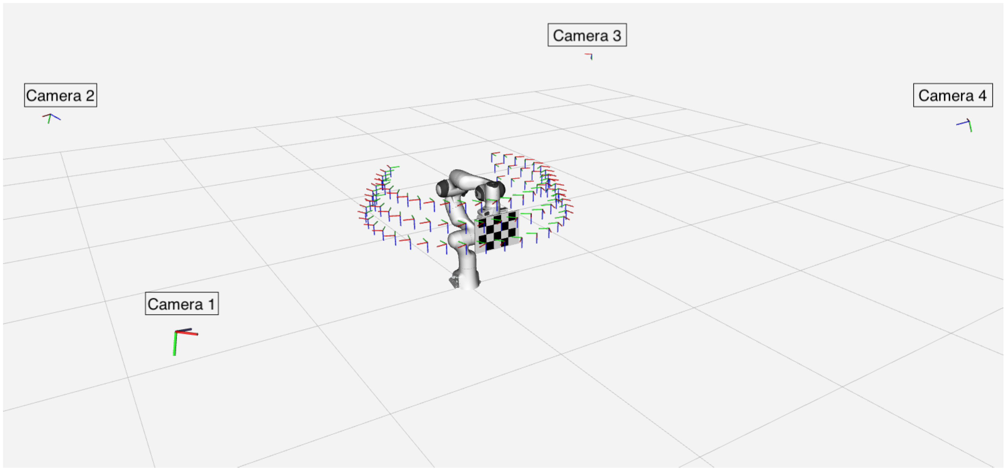
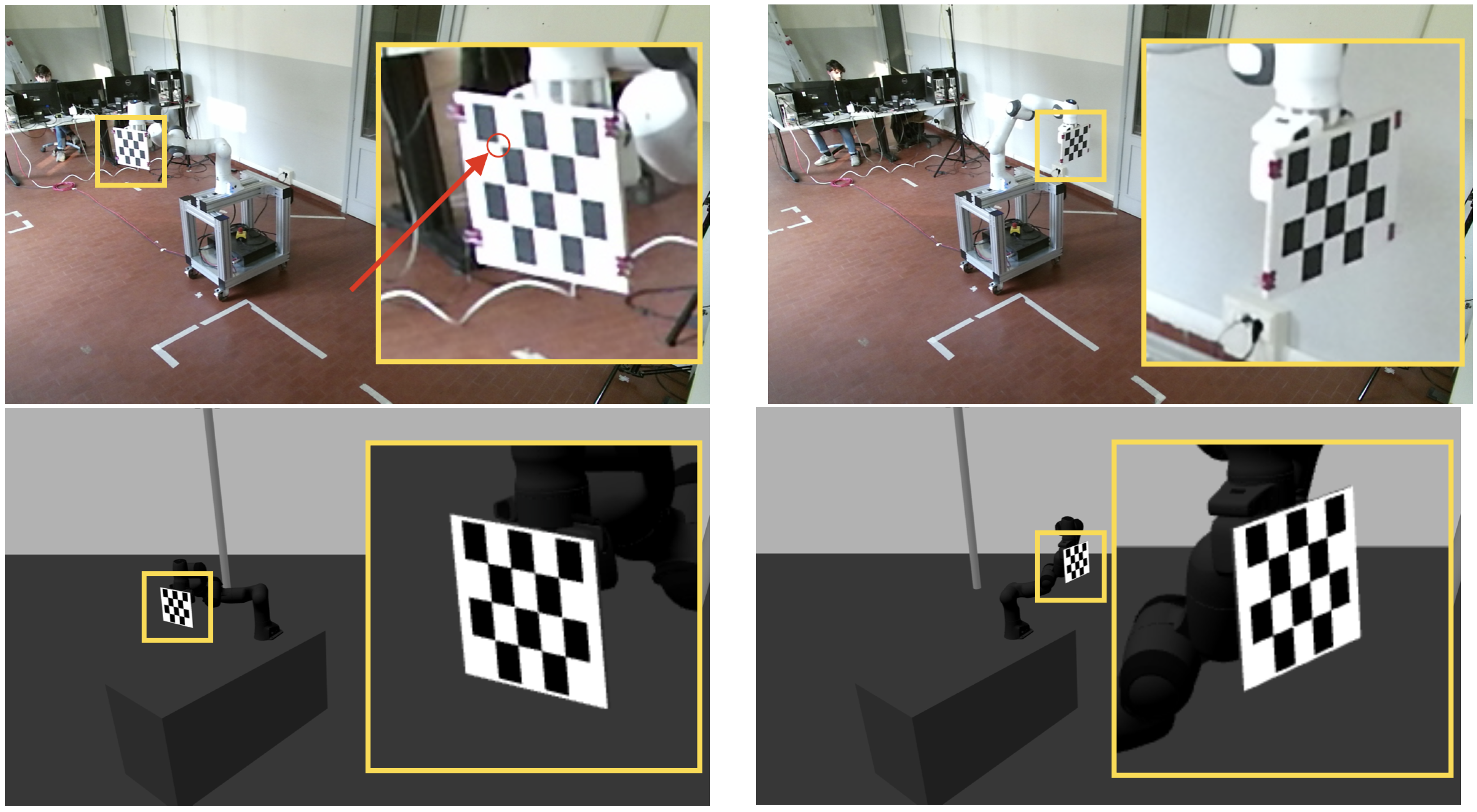
3.1. Synthetic Dataset
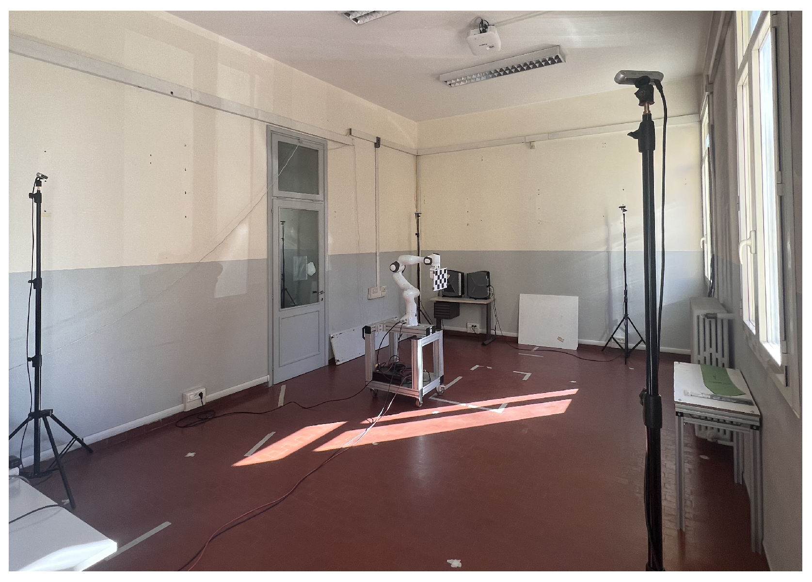
The synthetic dataset was created using the Gazebo simulation toolbox. A robotic workcell was simulated with a Panda robot arm and a network of Microsoft Kinect V2 cameras facing the robot, as depicted in Figure 3, with pre-defined intrinsic parameters.
The purpose of this dataset section is to provide synthetic data to evaluate the robustness of various camera network and robot-world hand-eye calibration methods at increasing distances between the sensors and the robot base. The simulated environment was diffusely illuminated by placing a sun model, provided by the Gazebo simulator, at a distance of 10 meters from the ground, avoiding the creation of potential shadows. This approach was chosen to focus the experiments and robustness evaluations on the distances between the sensors and the robot base. Acquisitions were performed with robotic workcells of different sizes, including small, medium, and large workcells, with varying values of height h of the cameras from the robot base, sensor-robot distance d, and length of the two workcell sides l 1 and l 2 , as shown in Figure 3 with the corresponding color, and as described in Table 1.
Each acquisition in the proposed dataset includes the ground truth provided by the simulator of the rototranslations of each camera relative to the robotic arm, as well as the relative rototranslation between each sensor belonging to the camera network. These data are crucial to accurately analyze the robustness of the calibration algorithms in the literature according to the distance from the calibration pattern and the impact of corner detection quality on the final result of the calibration process.

3.2. Real Dataset

The real dataset was collected at the Intelligent and Autonomous System Laboratory (IAS-Lab http://robotics.dei.unipd.it/, accessed on 2 May 2023) at the University of Padova, where a robotic workcell was set up with a Panda robot arm surrounded by a network of four cameras facing the manipulator, as depicted in Figure 4.
The real images were collected to assess the performance of the calibration methods in a real-world scenario where light reflections and image distortions can negatively affect the calibration process. Specifically, we collected data using sunlight as the primary light source through windows, as shown in Figure 4. We also acquired data from two robotic cells of different sizes — one small, similar to the simulated small cell, and the other as large as possible in the laboratory — to evaluate the methods in two possible scenarios, as specified in Table 2.
Each image acquisition involved three types of sensor:
These collections allowed us to evaluate calibration methods on real images and to analyze how the sensor characteristics, in particular their resolution and field of view (FoV), can influence the calibration process, according to their main technical specifications listed in Table 3.
In order to ensure consistency in the experiments with different sensors, we used the same method (findChessboardCorners) from the OpenCV library [35] for the detection of the calibration pattern control points across all three sensor types. This method was applied to the RGB image of each sensor, allowing us to evaluate the robustness of the cameras based on their RGB resolution and RGB field of view (FoV).
In this challenging calibration setup, where only a small pattern is used to allow the robot movements, a higher resolution sensor is expected to provide a more precise calibration. This is because a camera with a higher resolution can ensure greater accuracy in corner detection compared to a lower-resolution camera. In addition, a sensor with a larger FoV, such as the D455 depth camera, may have a negative effect on the calibration process in such a challenging setup with only one small calibration pattern because the pattern fills a smaller area of the camera’s image plane, making it more difficult to detect the corners accurately, especially as the distance increases.
The intrinsic parameters of the real cameras were accurately provided with the dataset. Specifically, the intrinsic parameters of the Microsoft Kinect V2 sensors were obtained through a previous separate procedure with respect to the rest of the experiments reported in Section 5, and it was performed individually for each camera. To perform an intrinsic calibration of these sensors, multiple images of a large checkerboard (7 × 6 with 11 cm square size) were captured by each camera. The calibration pattern was manually moved in front of each single camera in various positions and orientations at a distance of approximately 1 m in order to cover their entire image plane, which is a crucial element for a suitable intrinsic calibration. Then, the intrinsic parameters of each sensor, including the focal length, center point, and distortion coefficients, were estimated using Zhang’s method [7]. In contrast, for Intel’s LiDAR L515 and Depth D455 sensors, the factory-supplied intrinsic parameters were used.
Since the quality of the intrinsic calibration has a significant impact on extrinsic calibration and the overall reliability of the proposed dataset, it was essential to assess the accuracy of the determined intrinsic parameters. Therefore, a series of additional tests was performed. So, after completing an intrinsic calibration, a set of N = 20 images of the small checkerboard shown in Figure 2 with a known geometry was captured. Then, the corner reprojection error was computed by reprojecting the 3D corners of the checkerboard onto the image plane of each individual camera and calculating the Euclidean distance of these reprojected corners with the corresponding detected corners. The reprojection error results are shown in Table 4 for each camera in the network, representing the average error among all 20 images of the checkerboard.
As can be seen in the table, the intrinsic parameters of each camera ensure a reprojection error lower than 0.25 pixels. These results highlight the accuracy of the intrinsic parameters used for the experiments, increasing the reliability of the dataset and the relative experiments for the camera network and the robot-world hand-eye calibration.
Each real acquisition in the dataset includes the ground truth for the rototranslations between each sensor and the robot arm. This information was obtained by using an AprilTag with dimensions of 15 cm × 15 cm that was fixed in a precise position relative to the robot by means of a custom 3D-printed mount. Then, the rototranslations between the robot-base and the AprilTag were computed through the robot forward kinematics and the mount CAD model. On the other hand, the rototranslation between the camera and the AprilTag was determined using the official Apriltag library (https://github.com/AprilRobotics/apriltag, accessed on 1 May 2023), which has been shown to provide high accuracy for distances up to 5 m [36]. These two data were essential for determining the relative pose between each camera and the robot base and consequently to determine the rototranslations between sensors.

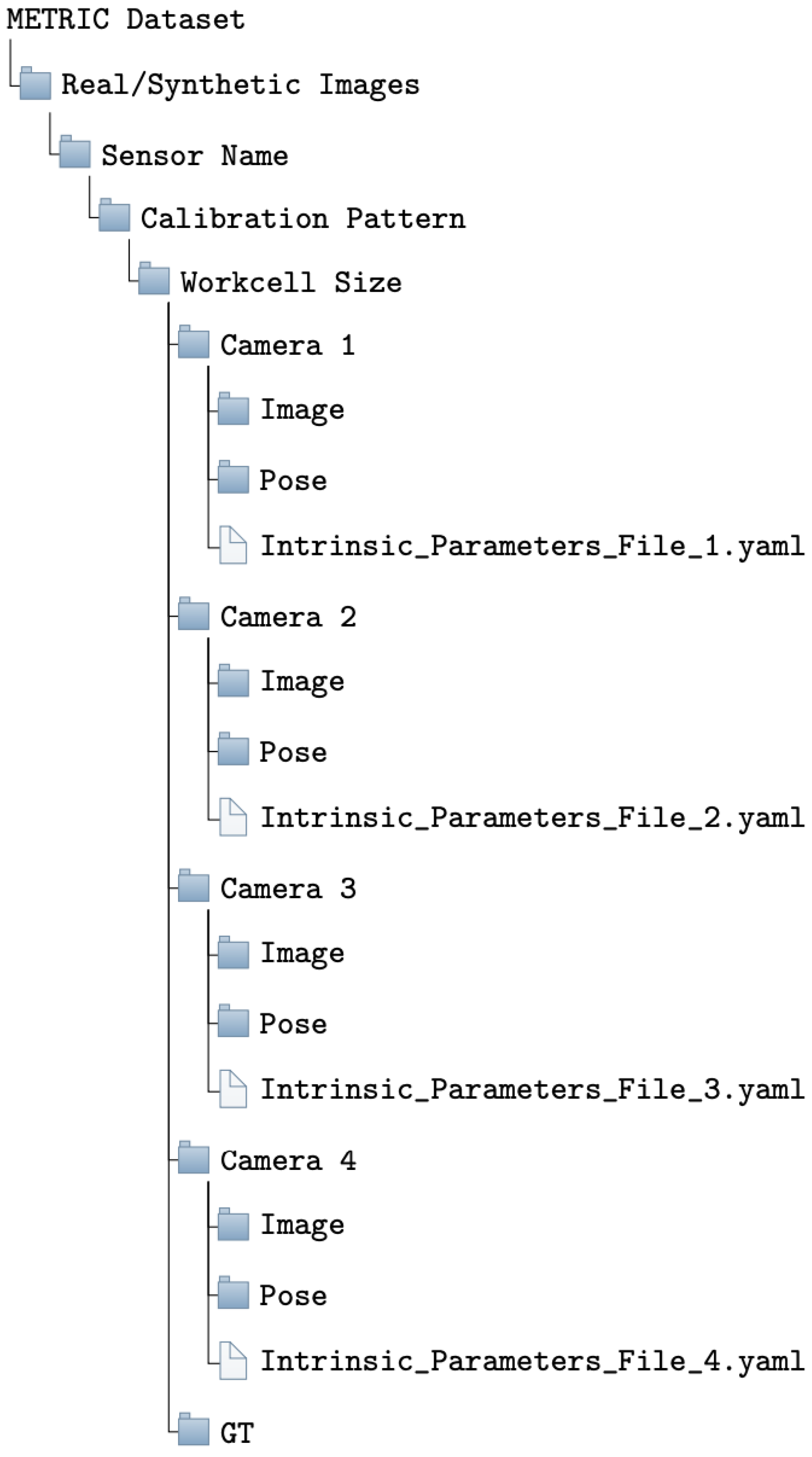
4. Dataset Structure

The METRIC dataset consists of over 10,000 synthetic and real images in PNG format, acquired within a robotic workcell by means of several image acquisitions, as described in Section 3. Specifically, the synthetic dataset was collected using a camera network consisting of Microsoft Kinect V2 cameras. The images were captured at the highest resolution possible, namely 1920 × 1280 pixels, without any data processing or adjustments.
On the other hand, the collection of real raw images was performed using the three different types of sensors mentioned in Section 3.2. In particular, the Microsoft Kinect V2 and Intel RealSense LiDAR L515 sensors acquired images with a resolution of 1920 × 1080 pixels, while the Intel RealSense Depth D455 sensor collected images of 1280 × 800 pixels, as listed in Table 3.
For each camera network setup, both synthetic and real image acquisitions were acquired twice using two different calibration patterns: the checkerboard and the ChAruCo pattern. Additionally, each captured image was accompanied by its corresponding robot pose, defined as a 4 × 4 matrix representing the geometric transformation between the robot base reference frame and the end-effector reference frame. These poses are provided in CSV files and are derived from the robot encoder, which provides the manipulator forward kinematics. Both the robot poses and the corresponding images are numbered from 1 (representing the first robot pose of the trajectory) to 250 (denoting the last robot pose achieved during the trajectory execution). Hence, the dataset structure can be outlined as follows (Figure 5):
The first four folders in the tree denote the type of dataset (synthetic or real), the sensor type, the calibration pattern, and the size of the workcell used for acquisition, which includes a folder for each camera. Within each Camera folder, there are two subfolders: the Image folder, which contains the 250 images captured by that specific camera during the image acquisition, and the Pose folder, which includes all the corresponding robot poses. Additionally, each camera folder contains a YAML file that provides the intrinsic parameters of the camera, including focal length, principal point offset, and distortion parameters necessary for the calibration process. The GT folder includes the ground truth of the geometric transformations in 4 × 4 matrix format between each camera reference frame and the robot base reference frame, stored in CSV format.
By organizing the dataset structure in this manner, researchers can easily navigate and access the relevant data, ensuring effective utilization of the METRIC dataset for their experiments. In particular, these structures can be used to perform experiments with any set of N sensors, with N ranging from 1 up to 4.

5. Experiments and Results

In this section, we provide a detailed description of the experiments we performed to test the various state-of-the-art methods on the proposed dataset, according to the two benchmarks for the two outlined use cases, namely, camera network calibration (Section 5.1) and robot-world hand-eye calibration (Section 5.2).
To evaluate the effectiveness of the calibration methods, we computed the translation error ( e t ) and rotation error ( e θ ) using the following equations:
e t = | | t t ^ | | 2
e θ = a n g l e ( R T R ^ )
Here, t and R are the translation vector and rotation matrix obtained from the ground truth data, while t ^ and R ^ are the estimated values. The function a n g l e converts a rotation matrix 3 × 3 into the average of the three corresponding Euler angles around the X, Y and Z axes in degrees.
The robotic workcell used for the experiments consists of the following main reference systems: the one coinciding with the robot base W and those corresponding to each of the four cameras comprising the network C j with j = 1 , , 4 . The benchmark for the camera network calibration use case evaluates the errors reported in Equations (1) and (2) by comparing the estimated geometric transformation T ^ C j C i between the j th and i th sensors of the camera network against the corresponding ground truth T C j C i . On the other hand, the benchmark for the robot-world hand-eye calibration use case assess the translation and the rotation errors by comparing the rototranslation matrix T ^ C i W between the ith sensor and the robot base W against its ground truth.

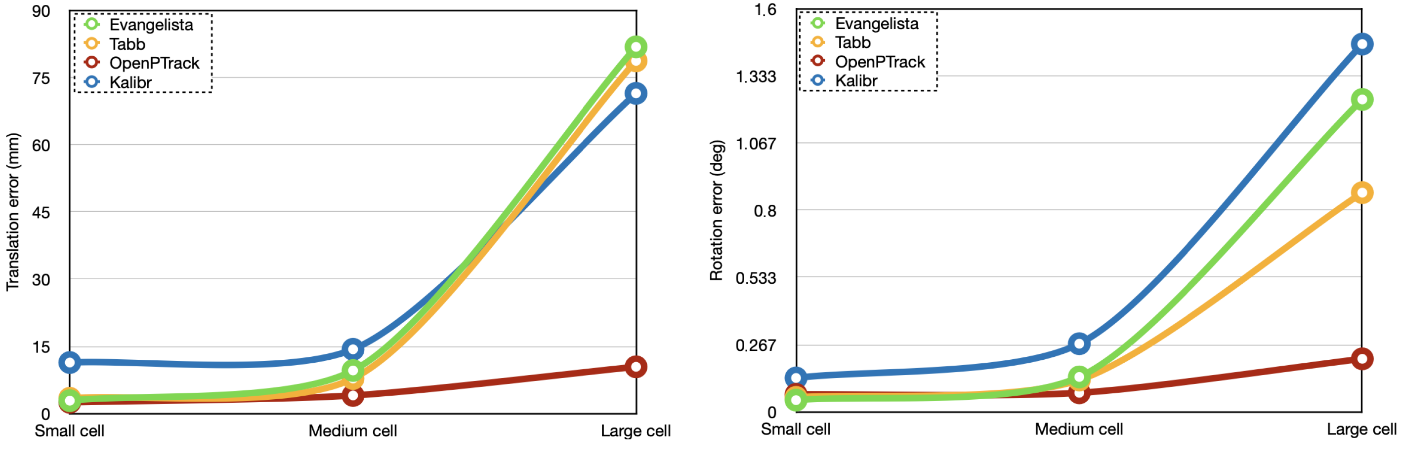
5.1. Camera Network Calibration

In order to perform a thorough analysis of the experiments, we selected some of the most popular calibration methods in the literature whose code was available. In addition to camera network calibration methods, we also selected robot-world hand-eye methods for camera network calibration use case. By iterating robot-world hand-eye calibration algorithms for the N sensor composing the camera network, it was possible to determine the rototranslation between each sensor and the robot base, and consequently the rototranslation between the various cameras within the network. This choice was made in order to assess whether robot-world hand-eye calibration systems could also be used to accurately calibrate a camera network and if there were any drawbacks. Specifically, the camera network calibration methods proposed in [13,25] were considered. They were then compared with two of the most recent robot-world hand-eye calibration methods in the literature: the calibration algorithm proposed in [27] and the method proposed by Tabb in [24], which focus on the minimization of the reprojection error. The analysis was performed on all the estimated rototranslations T ^ C i C j between the sensors couples belonging to the camera network, in the three different workcell sizes. The translation and rotation errors for each rototranslation, computed using Equations (1) and (2), are listed in Table A1 and Table A2, respectively, which can be found in Appendix A. Table 5 shows the results obtained by each of the methods mentioned above in terms of the average translation error [ m m ] and average rotation error [ d e g ] over all the rototranslations among the sensors belonging to the camera network, as described in Equation (3), and the corresponding standard deviation computed in Equation (4):
μ t = i = 1 N j = 1 N ( e t ) i , j N × ( N 1 ) μ θ = i = 1 N j = 1 N ( e θ ) i , j N × ( N 1 ) with i j
σ t = i = 1 N j = 1 N | | ( e t ) i , j μ t | | 2 N × ( N 1 ) σ θ = i = 1 N j = 1 N | | ( e θ ) i , j μ θ | | 2 N × ( N 1 ) with i j
where ( e t ) i , j and ( e θ ) i , j correspond to the translation and the rotation error of the rototranslation between the i th and j th sensors, and N is the number of sensors.
It is interesting to observe that the size of the workcell has a significant impact on both the translation and rotation errors. All methods, identified in Table 5 by the name of their framework if they have one, or by the name of their first author, showed an increase in such errors as the workcell dimensions also increased. This challenge is due to the limited coverage of the calibration pattern in the camera’s image plane, making it difficult to accurately detect corners. The OpenPTrack algorithm was found to be the most reliable across all three workcell sizes due to its ability to exploit simultaneous detection from multiple cameras. This makes the algorithm more robust to outliers during calibration, resulting in accurate results even in larger workcells.
The average translation and rotation errors of the state-of-the-art methods are better illustrated in Figure 6, highlighting how the calibration results are negatively affected by increasing workcell sizes.
The same calibration methods were evaluated even in the real images. The translation error and the rotation error for each rototranslation computed through Equations (1) and (2) are reported in Table A3, Table A4, Table A5 and Table A6, which can be found in Appendix A. In Table 6 and Table 7, the average camera network calibration results achieved with real images are presented, highlighting the differences obtained using different camera network types in two workcell configurations: small and large.
First of all, the translation and rotation errors obtained in the real small and real large workcells reported in Table 6 and Table 7, respectively, are higher than the errors obtained in all the simulated workcells reported in Table 5, as could be expected. Although the cameras in the small and large simulated workcells are placed at greater distances from the robot arm than the cameras in the corresponding real workcells, the synthetic images of the calibration pattern are significantly sharper than the real ones, thanks to the optimal lighting conditions and ideal intrinsic camera parameters provided by the simulator, as illustrated on the two bottom images in Figure 7. Instead, in real-world scenarios, cameras must also deal with non-ideal lighting conditions and imperfect intrinsic calibration parameters. These factors can affect the image quality in real-world situations, resulting in blurred image collections that have a negative impact on corner detection, as shown on the left top image in Figure 7, which was captured when the pattern was directly illuminated by the sunlight.
From Table 6 and Table 7, it can also be observed that the different sensors showed similar results in the real small workcell. Instead, in the real larger workcell, the LiDAR and Kinect V2 networks outperformed the Depth D455 network. This can be attributed to the narrower field of view of the LiDAR, which caused a pattern image that fills a larger area of camera image plane, resulting in more accurate detection of the control points and consequently in a more reliable calibration that was less affected by wrong detections. The Kinect V2 network also produced good results since it has a higher resolution than the Depth D455 sensors, as reported in Table 3. The Depth D455 network cannot ensure accurate calibration at such distances due to its wider field of view, which caused a pattern image covering a smaller area of the image plane, resulting in a less accurate corner detection. Indeed, all methods decrease their performance with such a sensor, and Kalibr’s optimization algorithm does not converge, showing limited robustness for this challenging setup. This failure is primarily attributed to the inability of multiple cameras to detect the calibration pattern simultaneously. The large workcell and the greater distances between the cameras and the robot arm pose present significant challenges in correctly identifying the pattern. Its tilted orientation, when within the field of view of two cameras, further complicates corner detection, making the calibration process extremely difficult for the Kalibr method, which exploits calibration pattern images detected simultaneously by multiple cameras. In contrast, other methods, such as Tabb’s and Evangelista’s algorithms, show at least some level of convergence because they are also designed to leverage calibration pattern images captured by a single camera. The calibration pattern in these images are typically more visible and nearly parallel to the camera’s image plane, improving the accuracy of the calibration pattern detection and contributing to the overall success of the calibration algorithm.

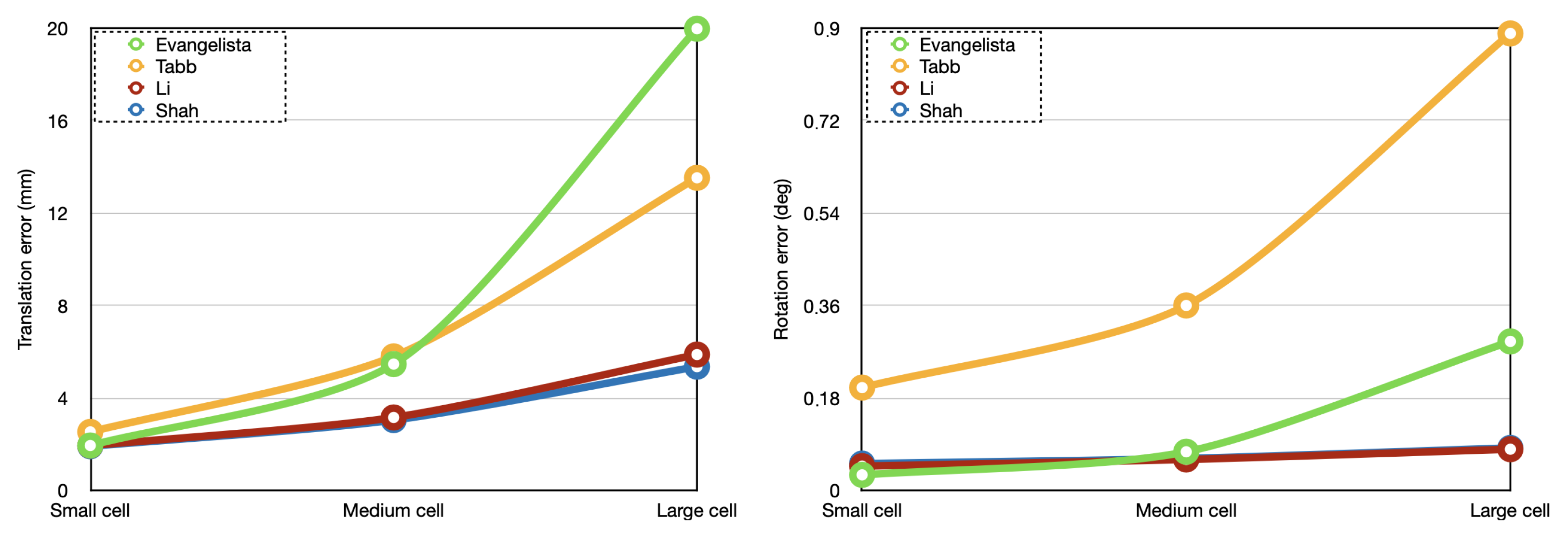
5.2. Robot-World Hand-Eye Calibration

This section provides a detailed description of the experiments performed on the proposed dataset to test various calibration methods according to the benchmark for the robot-world hand-eye calibration use case. In particular, we comprehensively compare four different calibration methods from the literature: the unified algorithm proposed by Evangelista et al. [27], Tabb’s method [24], and Shah’s and Li’s calibration methods [29,30]. The analysis of all these methods was performed accurately evaluating the translation and the rotation errors obtained through Equations (1) and (2) by comparing the estimated rototranslations between each camera C i with i = 1 , , 4 and the robot base W with the related ground truth. The metrics for the rototranslations between each camera and the robot are accurately listed in Table A7 and Table A8 in Appendix A. In Table 8, the average calibration results obtained in the three different simulated workcells with the four state-of-the-art methods are accurately reported. The accuracy was evaluated based on the average translation μ t and rotation errors μ θ and their corresponding standard deviations σ t and σ θ , computed by means of Equations (5) and (6):
μ t = i = 1 N ( e t ) i N μ θ = i = 1 N ( e θ ) i N
σ t = i = 1 N | | ( e t ) i μ t | | 2 N σ θ = i = 1 N | | ( e θ ) i μ θ | | 2 N
where the terms ( e t ) i and ( e t ) i denote the translation and rotation errors, respectively, of the rototranslation between the i th sensor and the robot base.
In order to illustrate the significant impact of workcell size on the results of robot-world hand-eye calibration methods, a detailed visual representation of the results has been provided in Figure 8.
As with camera network calibration, we observed that increasing the distance between each camera and the robot base can negatively affect corner detection and, consequently, the final calibration results. In particular it is interesting to observe that when the robot-sensor distance d (Table 1) is increased by approximately 30% from the small cell ( d = 2.05 m) to the medium cell ( d = 2.70 m), the translation error doubled with Tabb’s, Li’s and Shah’s method, and even tripled with Evenglista’s method. Similarly, the rotation error doubled with Tabb’s and Evangelista’s methods, and remained almost unchanged with Li’s and Shah’s algorithms. A further significant decline in performance occurred when the distance d was increased by a further 30% from the medium cell to the large cell ( d = 3.50 m). For all methods, the translation and rotation errors doubled, but they quadrupled for Evangelista’s method, being the most sensitive to the size of the robot workcell in the simulated experiments. On the other hand, the methods proposed by Shah and Li [29,30] were found to be more robust to outliers, even as the distance between each camera and the robot base increased.
These literature methods were also evaluated on the real dataset, specifically testing the robustness of the approaches when working on different sensor types. Table 9 and Table 10 show the robot-world hand-eye calibration results in terms of average translation and rotation errors, respectively. Appendix A contains Table A9 and Table A10, which list the errors obtained with each individual rototranslation error.
As expected, it can be observed that the differences among sensor types become more significant in larger workcells for this use case. Specifically, the LiDAR’s narrower field of view and the Kinect V2’s higher resolution led to better results, even in larger workcells. Furthermore, in most cases, the Shah method [30] and the Evangelista algorithm [27] were found to be slightly more robust than other methods. In particular, in the large workcell, the method of [27] was the most robust to outliers, while the optimization processes of [29,30] did not converge on the dataset collected in the workcell equipped with a camera network of Depth D455 sensors. Their failure to achieve convergence may be mainly due to the high sensitivity of their optimization algorithm, especially when inaccurate corner detection is prevalent. More specifically, their calibration process relies on the PnP algorithm, which is necessary to estimate the transformation between the camera and the calibration pattern. However, this approach can be imprecise and unreliable, since the camera pose is estimated considering a set of n 3D points in the world and their corresponding 2D projections in the single image, which can be blurred, negatively affecting the whole robot-world hand-eye calibration, as highlighted by the experiment results. On the other hand, alternative methods such as Evangelista’s and Tabb’s method have successfully achieved convergence with the Depth D455. These algorithms are based on the minimization of the reprojection error, which is more robust to outliers.

6. Conclusions

This work presented a novel dataset that combines both synthetic and real datasets to evaluate calibration methods based on two benchmarks for two use cases: camera network calibration and robot-world hand-eye calibration. The dataset is deliberately acquired in a robotic workcell, which is a real and challenging scenario for calibration problems. This choice was made to assess if the calibration methods can fulfill the requirements of a workcell, such as the need for larger camera networks and smaller calibration patterns. Therefore, METRIC includes a synthetic dataset acquired in robotic workcells of different sizes, starting from a smaller workcell representing an ideal situation where the calibration pattern is easily detectable, to larger workcells where the accurate corner detection is really challenging due to the glancing intersection of the rays at the projection center. This allows the assessment of methods with different camera network configurations and the comparison of estimated rototranslations with the corresponding ground truth provided in the synthetic dataset. Additionally, the real images in the dataset were captured using camera networks equipped with different sensor types, allowing for a detailed analysis of sensor performance in different workcell configurations. An analysis of the most recent and best-performing calibration methods for camera network calibration and robot-world hand-eye calibration was carried out, providing a baseline for our dataset. This baseline will allow researchers to compare and evaluate their future calibration works against the results presented in this paper. In future work, we plan to extend this dataset with other synthetic and real images collected on different workcell configurations, for example, using more than four cameras and incorporating different types of sensors into the same camera network. The resulting dataset will provide a benchmark to test and evaluate the performance of calibration methods in a wider range of scenarios. We plan to develop a novel calibration algorithm that outperforms other state-of-the-art methods and ensures a greater calibration accuracy for both camera network calibration and robot-world hand-eye calibration. Our aim is to develop a robust algorithm that can handle camera network calibration in larger robotic workcells, which has proven to be the most challenging problem for the methods found in the literature.

Author Contributions

Conceptualization, D.A., M.T. and S.G.; methodology, D.A. and M.T.; software, D.A.; validation, D.A.; formal analysis, D.A. and M.T.; investigation, D.A. and M.T.; resources, D.A.; data curation, D.A.; writing—original draft preparation, D.A.; writing—review and editing, D.A., M.T. and S.G.; visualization, D.A.; supervision, S.G.; project administration, S.G.; funding acquisition, S.G. All authors have read and agreed to the published version of the manuscript.

Funding

The research leading to these results has received funding from the European Union’s Horizon 2020 research and innovation program under grant agreement No. 101006732 (DrapeBot).

Data Availability Statement

The dataset proposed in this paper and used for the experiments is available at the following link https://doi.org/10.5281/zenodo.7976058, accessed on 3 April 2023.

Conflicts of Interest

The funders had no role in the design of the study; in the collection, analyses, or interpretation of data; in the writing of the manuscript, or in the decision to publish the results.

Appendix A

Table A1. Translation error of camera network calibration methods on the synthetic dataset.
Translation Error [mm]
T C 2 C 1 T C 3 C 1 T C 4 C 1 T C 1 C 2 T C 3 C 2 T C 4 C 2 T C 1 C 3 T C 2 C 3 T C 4 C 3 T C 1 C 4 T C 2 C 4 T C 3 C 4
SmallOpenPTrack [13]2.691.961.750.932.562.023.791.811.764.134.201.72
Kalibr [25]12.2313.4312.3110.2412.239.239.818.919.3612.3312.2113.72
Evangelista [27]2.343.553.132.001.983.713.802.722.313.094.330.79
Tabb RWHE [24]3.252.894.123.583.714.192.853.992.453.112.953.06
MediumOpenPTrack [13]3.653.352.261.972.004.014.883.473.076.997.824.26
Kalibr [25]13.2312.4515.679.4712.3218.2113.2812.3414.5419.3414.3616.24
Evangelista [27]7.4313.493.933.2413.4812.5518.2012.135.444.6111.029.12
Tabb RWHE [24]6.4411.784.648.989.127.236.277.948.115.028.239.44
LargeOpenPTrack [13]2.514.3415.164.863.739.9312.748.576.3923.1221.9511.29
Kalibr [25]47.3144.2438.1742.3632.3559.9372.3268.4396.73124.28121.89110.18
Evangelista [27]116.39112.93123.9977.6531.2160.8775.2432.4059.48125.2185.5581.24
Tabb RWHE [24]52.4568.6576.24112.5779.0583.9849.0184.1273.9481.3595.9287.34
Table A2. Rotation error of camera network calibration methods on the synthetic dataset.
Rotation Error [deg]
T C 2 C 1 T C 3 C 1 T C 4 C 1 T C 1 C 2 T C 3 C 2 T C 4 C 2 T C 1 C 3 T C 2 C 3 T C 4 C 3 T C 1 C 4 T C 2 C 4 T C 3 C 4
SmallOpenPTrack [13]0.070.080.050.090.040.050.150.080.040.070.060.05
Kalibr [25]0.130.110.130.120.180.090.150.130.120.130.170.15
Evangelista [27]0.050.030.050.040.060.060.040.030.040.060.050.05
Tabb RWHE [24]0.050.060.050.040.050.050.050.060.070.070.080.08
MediumOpenPTrack [13]0.060.040.110.060.050.070.050.090.120.060.110.08
Kalibr [25]0.160.240.320.380.210.270.290.270.130.350.380.28
Evangelista [27]0.190.150.070.100.300.120.140.140.160.070.090.13
Tabb RWHE [24]0.100.120.080.160.120.140.080.170.160.080.160.15
LargeOpenPTrack [13]0.060.080.480.060.170.160.080.170.340.460.180.32
Kalibr [25]1.400.581.321.670.981.621.211.981.321.872.131.45
Evangelista [27]1.120.981.231.321.290.321.120.481.922.870.691.65
Tabb RWHE [24]0.981.140.650.881.170.450.541.121.670.560.780.58
Table A3. Translation error of camera network calibration results on the real small workcell.
Small Workcell—Translation Error [mm]
T C 2 C 1 T C 3 C 1 T C 4 C 1 T C 1 C 2 T C 3 C 2 T C 4 C 2 T C 1 C 3 T C 2 C 3 T C 4 C 3 T C 1 C 4 T C 2 C 4 T C 3 C 4
Kinect V2OpenPTrack [13]80.84119.1350.3975.7233.6837.51120.4244.4780.1649.56100.8594.89
Kalibr [25]112.93109.24106.5495.57136.36127.44156.3298.73120.5786.36130.4398.39
Evangelista [27]62.1851.4487.9953.3479.5883.8135.0674.7429.5613.1460.5339.50
Tabb RWHE [24]56.7869.8973.6242.4839.3846.5252.3875.2365.4752.4973.4261.08
Depth D455OpenPTrack [13]73.52110.11100.53133.0571.9591.40141.1381.15104.5362.5582.15111.99
Kalibr [25]75.35147.28192.5495.3556.8789.54129.1276.33112.7371.84125.62134.28
Evangelista [27]85.7554.2767.3789.4773.1673.3757.3666.1414.6523.6752.7544.14
Tabb RWHE [24]59.4865.1469.4889.3853.5059.0874.3969.4854.7289.6892.5839.48
LiDAR L515OpenPTrack [13]58.92133.1833.8786.2923.3565.7394.0714.0390.4620.0277.59123.23
Kalibr [25]84.62127.83135.38152.14121.27121.3271.35121.46143.7384.6776.75125.34
Evangelista [27]61.1117.1921.0139.7672.0861.5515.4363.4117.959.8646.2632.79
Tabb RWHE [24]45.6835.6824.7432.4841.5552.5339.4842.6824.6219.5834.5346.38
Table A4. Rotation error of camera network calibration results on the real small workcell.
Small Workcell—Rotation Error [deg]
T C 2 C 1 T C 3 C 1 T C 4 C 1 T C 1 C 2 T C 3 C 2 T C 4 C 2 T C 1 C 3 T C 2 C 3 T C 4 C 3 T C 1 C 4 T C 2 C 4 T C 3 C 4
Kinect V2OpenPTrack [13]0.570.620.781.231.350.971.251.120.891.271.430.78
Kalibr [25]1.781.031.431.981.481.181.232.111.671.481.651.56
Evangelista [27]0.560.400.210.580.770.480.400.580.360.300.500.40
Tabb RWHE [24]0.780.891.131.241.210.920.671.101.200.570.780.58
Depth D455OpenPTrack [13]1.561.340.340.880.320.991.340.571.880.461.211.39
Kalibr [25]1.982.891.922.762.432.121.982.342.761.892.062.88
Evangelista [27]0.450.240.220.440.530.630.210.870.440.370.690.40
Tabb RWHE [24]1.211.561.761.320.971.561.091.571.721.091.451.36
LiDAR L515OpenPTrack [13]1.761.730.531.120.711.331.580.652.380.651.272.88
Kalibr [25]1.521.241.761.561.522.111.291.771.981.431.731.82
Evangelista [27]0.340.780.250.381.070.290.950.471.820.110.251.59
Tabb RWHE [24]1.430.780.880.920.730.840.871.121.371.250.981.34
Table A5. Translation error of camera network calibration results on the real large workcell (“−” denotes that the calibration algorithm does not converge).
Large Workcell—Translation Error [mm]
T C 2 C 1 T C 3 C 1 T C 4 C 1 T C 1 C 2 T C 3 C 2 T C 4 C 2 T C 1 C 3 T C 2 C 3 T C 4 C 3 T C 1 C 4 T C 2 C 4 T C 3 C 4
Kinect V2OpenPTrack [13]138.22178.2591.25180.0165.6027.32250.9477.12105.4375.97232.63184.21
Kalibr [25]122.46125.36121.4797.4685.36138.48184.37125.46145.57175.58184.53136.81
Evangelista [27]70.82116.8047.1893.4582.5358.3463.8678.1737.3427.9473.4090.83
Tabb RWHE [24]60.7168.2280.1345.3250.6284.2345.3273.5678.4939.6769.1988.31
Depth D455OpenPTrack [13]135.53226.54236.74147.63243.73174.22342.60196.19306.91193.36138.32299.51
Kalibr [25]
Evangelista [27]80.03206.39168.55148.34246.65143.02253.20196.19306.91185.06112.24304.51
Tabb RWHE [24]78.82174.53110.34102.43198.42138.32296.22171.24194.36170.42145.81206.35
LiDAR L515OpenPTrack [13]158.22153.2572.34157.3978.8845.68198.3998.4988.8869.89187.29163.99
Kalibr [25]236.57153.25128.68165.32128.5896.38143.4486.32125.35133.35146.38179.62
Evangelista [27]95.18110.0750.02105.2660.3474.0170.3766.2468.2851.0790.3476.64
Tabb RWHE [24]45.5265.9875.3469.2593.2388.2475.3845.5789.3857.4893.2467.78
Table A6. Rotation error of camera network calibration results on the real large workcell (“−” denotes that the calibration algorithm does not converge).
Large Workcell—Rotation Error [deg]
T C 2 C 1 T C 3 C 1 T C 4 C 1 T C 1 C 2 T C 3 C 2 T C 4 C 2 T C 1 C 3 T C 2 C 3 T C 4 C 3 T C 1 C 4 T C 2 C 4 T C 3 C 4
Kinect V2OpenPTrack [13]1.982.230.831.530.790.832.090.744.210.971.733.29
Kalibr [25]3.233.012.782.523.122.782.882.393.412.491.883.12
Evangelista [27]0.590.980.450.470.610.280.980.561.210.460.321.18
Tabb RWHE [24]2.120.872.232.372.412.891.321.091.991.881.581.92
Depth D455OpenPTrack [13]3.231.573.891.883.722.544.261.432.393.281.513.23
Kalibr [25]
Evangelista [27]1.311.841.651.561.981.232.352.483.782.131.422.89
Tabb RWHE [24]2.784.213.245.031.893.254.322.233.204.873.044.14
LiDAR L515OpenPTrack [13]0.741.231.260.730.811.991.561.831.452.191.333.01
Kalibr [25]3.213.452.081.282.782.083.291.882.971.203.832.68
Evangelista [27]0.310.850.400.391.050.210.950.671.720.240.201.53
Tabb RWHE [24]1.721.040.851.891.572.991.891.721.860.992.051.59
Table A7. Translation error of robot-world hand-eye methods on the synthetic dataset.
Translation Error [mm]
SmallMediumLarge
T C 1 W T C 2 W T C 3 W T C 4 W T C 1 W T C 2 W T C 3 W T C 4 W T C 1 W T C 2 W T C 3 W T C 4 W
Evangelista [27]1.631.992.141.972.465.6011.032.7425.1115.3517.6121.83
Tabb RWHE [24]2.422.601.703.375.252.857.217.8514.8913.788.9016.54
Li [29]2.222.262.071.162.834.032.872.854.2012.323.033.93
Shah [30]2.042.192.051.332.803.802.772.763.0710.993.044.28
Table A8. Rotation error of robot-world hand-eye methods on the synthetic dataset.
Rotation Error [deg]
SmallMediumLarge
T C 1 W T C 2 W T C 3 W T C 4 W T C 1 W T C 2 W T C 3 W T C 4 W T C 1 W T C 2 W T C 3 W T C 4 W
Evangelista [27]0.020.030.030.040.030.080.150.040.280.140.190.56
Tabb RWHE [24]0.230.280.130.160.540.490.310.111.560.590.440.98
Li [29]0.050.060.040.040.080.040.060.060.060.120.050.09
Shah [30]0.050.070.040.050.080.050.060.060.050.150.050.08
Table A9. Translation error of robot-world hand-eye calibration methods on the real dataset (“−” denotes that the calibration algorithm does not converge).
Translation Error [mm]
Small WorkcellLarge Workcell
T C 1 W T C 2 W T C 3 W T C 4 W T C 1 W T C 2 W T C 3 W T C 4 W
Kinect V2Evangelista [27]29.3476.2038.9126.7182.6186.4060.7179.32
Tabb RWHE [24]34.2486.5443.2142.3197.35123.23101.2398.23
Li [29]79.5834.5264.6887.91134.86106.23101.00175.45
Shah [30]30.3131.9214.9831.6646.2145.3859.7268.38
Depth D455Evangelista [27]57.9764.4330.1927.9873.8283.18236.55152.01
Tabb RWHE [24]69.6593.3546.6746.23129.24102.23182.34198.33
Li [29]39.9247.0170.7046.51
Shah [30]12.1223.3822.2137.89
LiDAR L515Evangelista [27]10.4157.1925.4511.7459.9271.6866.2944.47
Tabb RWHE [24]15.2354.3545.3423.4689.3479.3373.2259.43
Li [29]17.7431.6920.3625.0118.1334.6021.5231.30
Shah [30]14.3416.9415.8126.9516.8035.7627.1224.89
Table A10. Rotation error of robot-world hand-eye calibration methods on the real dataset (“−” denotes that the calibration algorithm does not converge).
Rotation Error [deg]
Small WorkcellLarge Workcell
T C 1 W T C 2 W T C 3 W T C 4 W T C 1 W T C 2 W T C 3 W T C 4 W
Kinect V2Evangelista [27]0.500.820.370.570.930.540.401.21
Tabb RWHE [24]0.650.780.540.980.790.690.580.97
Li [29]1.050.650.630.591.260.530.630.49
Shah [30]0.850.670.730.751.030.430.690.79
Depth D455Evangelista [27]0.480.810.130.290.990.542.541.27
Tabb RWHE [24]1.231.651.590.991.571.432.141.83
Li [29]0.120.871.430.47
Shah [30]0.250.780.310.83
LiDAR L515Evangelista [27]0.450.230.390.520.510.330.490.42
Tabb RWHE [24]0.760.931.230.870.890.720.690.79
Li [29]0.290.380.190.390.280.320.210.42
Shah [30]0.320.480.170.390.270.420.180.39

References

  1. Dong, Z.; Song, J.; Chen, X.; Guo, C.; Hilliges, O. Shape-aware multi-person pose estimation from multi-view images. In Proceedings of the IEEE/CVF International Conference on Computer Vision, Montreal, BC, Canada, 11–17 October 2021; pp. 11158–11168. [Google Scholar]
  2. Golda, T.; Kalb, T.; Schumann, A.; Beyerer, J. Human pose estimation for real-world crowded scenarios. In Proceedings of the 2019 16th IEEE International Conference on Advanced Video and Signal Based Surveillance (AVSS), Taipei, Taiwan, 18–21 September 2019; pp. 1–8. [Google Scholar]
  3. Cortés, I.; Beltrán, J.; de la Escalera, A.; García, F. Sianms: Non-maximum suppression with siamese networks for multi-camera 3d object detection. In Proceedings of the 2020 IEEE Intelligent Vehicles Symposium (IV), Las Vegas, NV, USA, 19 October–13 November 2020; pp. 933–938. [Google Scholar]
  4. Quintana, M.; Karaoglu, S.; Alvarez, F.; Menendez, J.M.; Gevers, T. Three-D Wide Faces (3DWF): Facial Landmark Detection and 3D Reconstruction over a New RGB–D Multi-Camera Dataset. Sensors 2019, 19, 1103. [Google Scholar] [CrossRef] [PubMed]
  5. Terreran, M.; Lamon, E.; Michieletto, S.; Pagello, E. Low-cost scalable people tracking system for human-robot collaboration in industrial environment. Procedia Manuf. 2020, 51, 116–124. [Google Scholar] [CrossRef]
  6. Zhu, L.; Menon, M.; Santillo, M.; Linkowski, G. Occlusion Handling for Industrial Robots. In Proceedings of the 2020 IEEE/RSJ International Conference on Intelligent Robots and Systems (IROS), Las Vegas, NV, USA, 24 October–24 January 2021; pp. 10663–10668. [Google Scholar]
  7. Zhang, Z. A flexible new technique for camera calibration. IEEE Trans. Pattern Anal. Mach. Intell. 2000, 22, 1330–1334. [Google Scholar] [CrossRef]
  8. Sturm, P.F.; Maybank, S.J. On plane-based camera calibration: A general algorithm, singularities, applications. In Proceedings of the Proceedings. 1999 IEEE Computer Society Conference on Computer Vision and Pattern Recognition (Cat. No PR00149), Fort Collins, CO, USA, 23–25 June 1999; Volume 1, pp. 432–437. [Google Scholar]
  9. Tsai, R. A versatile camera calibration technique for high-accuracy 3D machine vision metrology using off-the-shelf TV cameras and lenses. IEEE J. Robot. Autom. 1987, 3, 323–344. [Google Scholar] [CrossRef]
  10. Garrido-Jurado, S.; Muñoz-Salinas, R.; Madrid-Cuevas, F.J.; Marín-Jiménez, M.J. Automatic generation and detection of highly reliable fiducial markers under occlusion. Pattern Recognit. 2014, 47, 2280–2292. [Google Scholar] [CrossRef]
  11. Shen, J.; Xu, W.; Luo, Y.; Su, P.C.; Cheung, S.C.S. Extrinsic calibration for wide-baseline RGB-D camera network. In Proceedings of the 2014 IEEE 16th International Workshop on Multimedia Signal Processing (MMSP), Jakarta, Indonesia, 22–24 September 2014; pp. 1–6. [Google Scholar]
  12. Kim, E.S.; Park, S.Y. Extrinsic calibration of a camera-LIDAR multi sensor system using a planar chessboard. In Proceedings of the 2019 Eleventh International Conference on Ubiquitous and Future Networks (ICUFN), Zagreb, Croatia, 2–5 July 2019; pp. 89–91. [Google Scholar]
  13. Munaro, M.; Basso, F.; Menegatti, E. OpenPTrack: Open source multi-camera calibration and people tracking for RGB-D camera networks. Robot. Auton. Syst. 2016, 75, 525–538. [Google Scholar] [CrossRef]
  14. Hödlmoser, M.; Kampel, M. Multiple camera self-calibration and 3D reconstruction using pedestrians. In Proceedings of the Advances in Visual Computing: 6th International Symposium, ISVC 2010, Las Vegas, NV, USA, 29 November–1 December 2010; Proceedings, Part II 6. Springer: Berlin/Heidelberg, Germany, 2010; pp. 1–10. [Google Scholar]
  15. Le, Q.V.; Ng, A.Y. Joint calibration of multiple sensors. In Proceedings of the 2009 IEEE/RSJ International Conference on Intelligent Robots and Systems, St. Louis, MO, USA, 10–15 October 2009; pp. 3651–3658. [Google Scholar]
  16. Zhu, Y.; Wu, Y.; Zhang, Y.; Qu, F. Multi-camera System Calibration of Indoor Mobile Robot Based on SLAM. In Proceedings of the 2021 3rd International Conference on Machine Learning, Big Data and Business Intelligence (MLBDBI), Taiyuan, China, 3–5 December 2021; pp. 240–244. [Google Scholar]
  17. Kroeger, O.; Huegle, J.; Niebuhr, C.A. An automatic calibration approach for a multi-camera-robot system. In Proceedings of the 2019 24th IEEE International Conference on Emerging Technologies and Factory Automation (ETFA), Zaragoza, Spain, 10–13 September 2019; pp. 1515–1518. [Google Scholar]
  18. Mišeikis, J.; Glette, K.; Elle, O.J.; Torresen, J. Automatic Calibration of a Robot Manipulator and Multi 3D Camera System. In Proceedings of the 2016 IEEE/SICE International Symposium on System Integration (SII), Sapporo, Japan, 13–15 December 2016; pp. 735–741. [Google Scholar]
  19. Sung, H.; Lee, S.; Kim, D. A robot-camera hand/eye self-calibration system using a planar target. In Proceedings of the IEEE ISR 2013, Seoul, Republic of Korea, 24–26 October 2013; pp. 1–4. [Google Scholar]
  20. Šuligoj, F.; Jerbić, B.; Švaco, M.; Šekoranja, B.; Mihalinec, D.; Vidaković, J. Medical applicability of a low-cost industrial robot arm guided with an optical tracking system. In Proceedings of the 2015 IEEE/RSJ International Conference on Intelligent Robots and Systems (IROS), Hamburg, Germany, 28 September–2 October 2015; pp. 3785–3790. [Google Scholar]
  21. Su, P.C.; Shen, J.; Xu, W.; Cheung, S.C.S.; Luo, Y. A fast and robust extrinsic calibration for RGB-D camera networks. Sensors 2018, 18, 235. [Google Scholar] [CrossRef]
  22. Tabb, A.; Medeiros, H.; Feldmann, M.J.; Santos, T.T. Calibration of Asynchronous Camera Networks: CALICO. arXiv 2019, arXiv:1903.06811. [Google Scholar]
  23. Wang, Y.; Jiang, W.; Huang, K.; Schwertfeger, S.; Kneip, L. Accurate Calibration of Multi-Perspective Cameras from a Generalization of the Hand-Eye Constraint. In Proceedings of the 2022 International Conference on Robotics and Automation (ICRA), Philadelphia, PA, USA, 23–27 May 2022; pp. 1244–1250. [Google Scholar] [CrossRef]
  24. Tabb, A.; Ahmad Yousef, K.M. Solving the robot-world hand-eye (s) calibration problem with iterative methods. Mach. Vis. Appl. 2017, 28, 569–590. [Google Scholar] [CrossRef]
  25. Furgale, P.; Rehder, J.; Siegwart, R. Unified temporal and spatial calibration for multi-sensor systems. In Proceedings of the 2013 IEEE/RSJ International Conference on Intelligent Robots and Systems, Tokyo, Japan, 3–7 November 2013; pp. 1280–1286. [Google Scholar]
  26. Caron, G.; Eynard, D. Multiple camera types simultaneous stereo calibration. In Proceedings of the 2011 IEEE International Conference on Robotics and Automation, Shanghai, China, 9–13 May 2011; pp. 2933–2938. [Google Scholar]
  27. Evangelista, D.; Allegro, D.; Terreran, M.; Pretto, A.; Ghidoni, S. An Unified Iterative Hand-Eye Calibration Method for Eye-on-Base and Eye-in-Hand Setups. In Proceedings of the 2022 IEEE 27th International Conference on Emerging Technologies and Factory Automation (ETFA), Stuttgart, Germany, 6–9 September 2022; pp. 1–7. [Google Scholar]
  28. Schweighofer, G.; Pinz, A. Globally Optimal O (n) Solution to the PnP Problem for General Camera Models. In BMVC; BMVA Press: Leeds, UK, 2008; pp. 1–10. [Google Scholar]
  29. Li, A.; Wang, L.; Wu, D. Simultaneous robot-world and hand-eye calibration using dual-quaternions and Kronecker product. Int. J. Phys. Sci. 2010, 5, 1530–1536. [Google Scholar]
  30. Shah, M. Solving the robot-world/hand-eye calibration problem using the Kronecker product. J. Mech. Robot. 2013, 5, 031007. [Google Scholar] [CrossRef]
  31. Hüser, T.; Sheshadri, S.; Dörge, M.; Scherberger, H.; Dann, B. JARVIS-MoCap Monkey Grasping Recordings and Annotations. 2022. Available online: https://doi.org/10.5281/zenodo.6982805 (accessed on 3 March 2023).
  32. Skaloud, J.; Cucci, D.A.; Joseph Paul, K. Coaxial Octocopter Open Data with Digicam—IGN Calibration 2. 2021. Available online: https://doi.org/10.5281/zenodo.4705424 (accessed on 3 March 2023).
  33. Koide, K.; Menegatti, E. General hand—Eye calibration based on reprojection error minimization. IEEE Robot. Autom. Lett. 2019, 4, 1021–1028. [Google Scholar] [CrossRef]
  34. Quigley, M.; Conley, K.; Gerkey, B.; Faust, J.; Foote, T.; Leibs, J.; Wheeler, R.; Ng, A.Y.; Berger, E. ROS: An open-source Robot Operating System. In Proceedings of the ICRA Workshop on Open Source Software, Kobe, Japan, 12–17 May 2009; Volume 3, p. 5. [Google Scholar]
  35. Bradski, G. The openCV library. Dr. Dobb’s J. Softw. Tools Prof. Program. 2000, 25, 120–123. [Google Scholar]
  36. Wang, J.; Olson, E. AprilTag 2: Efficient and robust fiducial detection. In Proceedings of the 2016 IEEE/RSJ International Conference on Intelligent Robots and Systems (IROS), Daejeon, Republic of Korea, 9–14 October 2016; pp. 4193–4198. [Google Scholar]
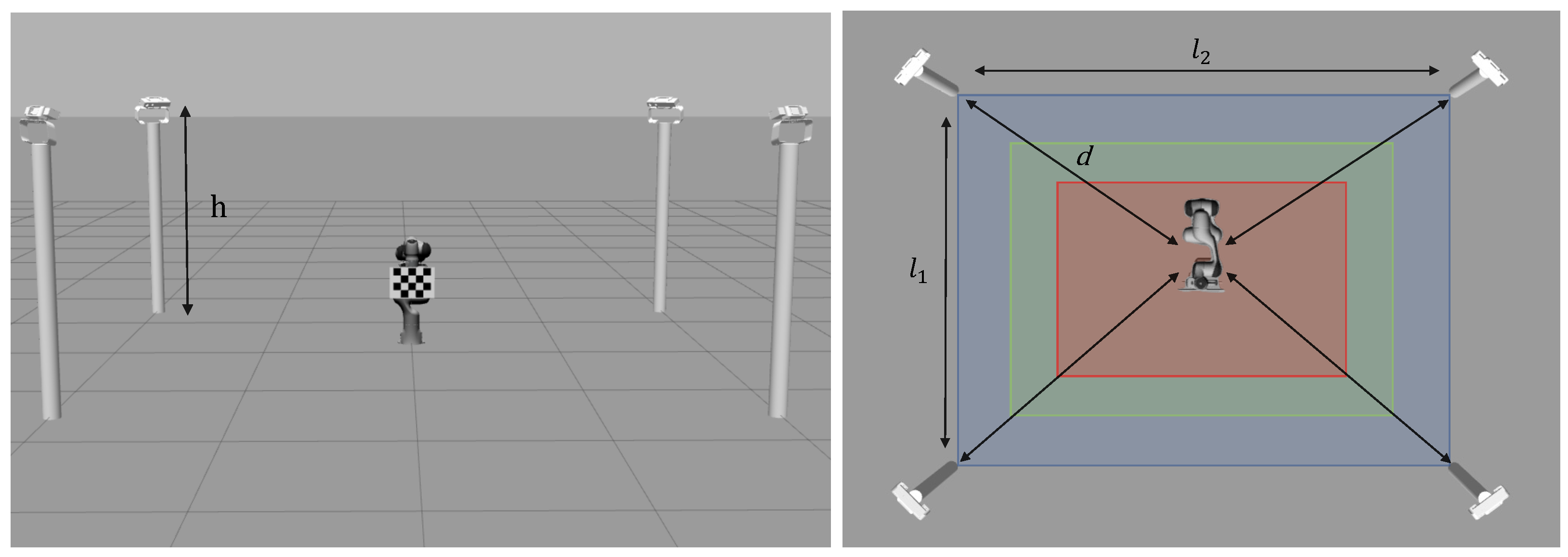
Figure 1. Waypoints of the hemispherical planned trajectory, followed by the robot end-effector during the image acquisition, with the checkerboard facing the camera network both in the synthetic and real dataset.
Information 14 00314 g001
Figure 2. Checkerboard 5 × 4 on the left; ChAruCo pattern 5 × 4 with marker dictionary 6 × 6 on the right. They both consist of grids of 5 cm size squares.
Information 14 00314 g002
Figure 3. Simulated robotic workcell from a side view on the left; robotic workcell from a top view on the right.
Information 14 00314 g003
Figure 4. Large-scale real workcell equipped with a Panda robot arm with a checkerboard attached on its end-effector, surrounded by four Intel RealSense Depth D455 cameras.
Information 14 00314 g004
Figure 5. Structure of the METRIC dataset.
Information 14 00314 g005
Figure 6. Calibration results obtained from synthetic data with camera network calibration methods from the literature; average translation error [ m m ] on the left; average rotation error [ d e g ] on the right.
Information 14 00314 g006
Figure 7. The two images above show real images from our dataset, captured with the Kinect V2 camera in the large workcell. The image on the left shows an over-exposure condition that can occur in a real-world scenario, resulting in blurred corners of the calibration pattern as highlighted by the arrow. The image on the right, taken in better lighting conditions, gives a clearer view of the calibration pattern. On the other hand, the simulated images on the bottom show that this problem does not exist due to the optimal lighting conditions and ideal intrinsic camera parameters provided by the simulator.
Information 14 00314 g007
Figure 8. Calibration results on synthetic data obtained with four different robot-world hand-eye calibration methods; average translation error [ m m ] on the left; average rotation error [ d e g ] on the right.
Information 14 00314 g008
Table 1. Main dimensions for the three workcells considered in the synthetic dataset: small, medium and large.
Workcell SizesColourh [m]d [m] l 1 [m] l 2 [m]
Small workcellInformation 14 00314 i001 1.00 2.05 2.00 3.00
Medium workcellInformation 14 00314 i002 1.00 2.70 3.00 4.00
Large workcellInformation 14 00314 i003 1.50 3.50 4.00 5.00
Table 2. Real workcell sizes.
Workcell Sizesh [m]d [m] l 1 [m] l 2 [m]
Small workcell 1.25 2.30 2.25 3.25
Large workcell 1.25 2.90 3.00 5.00
Table 3. Sensor specifications.
Kinect V2Depth Camera D455LiDAR Camera L515
RGB resolution 1920 × 1080 1280 × 800 1920 × 1080
RGB FoV ( h × v ) 84 . 1 × 53 . 8 90 × 65 70 × 43
Table 4. The results of intrinsic calibration for each camera are presented in terms of the corner reprojection error in pixels.
Kinect V2 [pixel]Depth D455 [pixel]LiDAR L515 [pixel]
Camera 1 0.203 0.134 0.197
Camera 2 0.170 0.161 0.203
Camera 3 0.153 0.132 0.187
Camera 4 0.172 0.124 0.160
Average 0.174 0.138 0.187
Table 5. Average translation and rotation error related to camera network calibration on synthetic dataset; the bold results denote the lowest error achieved by the best calibration method in the corresponding scenario.
MethodSmall CellMedium CellLarge Cell
μ t ± σ t
[mm]
μ θ ± σ θ
[deg]
μ t ± σ t
[mm]
μ θ ± σ θ
[deg]
μ t ± σ t
[mm]
μ θ ± σ θ
[deg]
OpenPTrack [13] 2.44 ± 0.86 0.07 ± 0.02 3.97 ± 1.35 0.07 ± 0.02 10.38 ± 5.40 0.21 ± 0.14
Kalibr [25] 11.33 ± 1.52 0.13 ± 0.02 14.29 ± 2.11 0.27 ± 0.07 71.52 ± 27.97 1.46 ± 0.41
Evangelista [27] 2.81 ± 0.79 0.04 ± 0.01 9.55 ± 3.93 0.14 ± 0.06 81.85 ± 25.81 1.25 ± 0.65
Tabb [24] 3.35 ± 0.48 0.06 ± 0.01 7.77 ± 1.54 0.12 ± 0.03 78.71 ± 12.22 0.87 ± 0.34
Table 6. Average translation and rotation error of camera network calibration methods on the small-size workcell in the real dataset; the bold results denote the lowest error achieved by the best calibration method in the corresponding scenario.
MethodKinect V2Depth D455LiDAR L515
μ t ± σ t
[mm]
μ θ ± σ θ
[deg]
μ t ± σ t
[mm]
μ θ ± σ θ
[deg]
μ t ± σ t
[mm]
μ θ ± σ θ
[deg]
OpenPTrack [13] 73.97 ± 25.71 1.02 ± 0.28 89.51 ± 25.86 1.02 ± 0.49 68.40 ± 32.41 1.38 ± 0.70
Kalibr [25] 114.90 ± 16.10 1.54 ± 0.30 108.91 ± 31.36 2.33 ± 0.38 113.82 ± 22.98 1.64 ± 0.25
Evangelista [27] 55.91 ± 18.90 0.46 ± 0.14 58.51 ± 17.37 0.45 ± 0.19 38.20 ± 19.16 0.69 ± 0.53
Tabb [24] 59.06 ± 10.72 0.92 ± 0.23 68.03 ± 12.80 1.38 ± 0.24 36.66 ± 8.06 1.04 ± 0.23
Table 7. Average translation and rotation error of camera network calibration methods on the large-size workcell in the real dataset; the bold results denote the lowest error achieved by the best calibration method in the corresponding scenario (“−” denotes that the calibration algorithm does not converge).
MethodKinect V2Depth D455LiDAR L515
μ t ± σ t
[mm]
μ θ ± σ θ
[deg]
μ t ± σ t
[mm]
μ θ ± σ θ
[deg]
μ t ± σ t
[mm]
μ θ ± σ θ
[deg]
OpenPTrack [13] 133.91 ± 60.13 1.76 ± 1.04 220.35 ± 56.14 2.74 ± 0.95 122.72 ± 47.03 1.51 ± 0.64
Kalibr [25] 136.90 ± 24.00 2.80 ± 0.41 143.60 ± 27.19 2.56 ± 0.81
Evangelista [27] 70.06 ± 19.27 0.67 ± 0.31 195.92 ± 56.39 2.05 ± 0.71 76.49 ± 15.84 0.71 ± 0.49
Tabb [24] 65.31 ± 14.16 1.89 ± 0.57 165.61 ± 42.07 3.51 ± 0.96 72.19 ± 13.61 1.68 ± 0.54
Table 8. Average translation and rotation error of robot-world hand-eye calibration methods on synthetic dataset; the bold results denote the lowest error achieved by the best calibration method in the corresponding scenario.
MethodSmall CellMedium CellLarge Cell
μ t ± σ t
[mm]
μ θ ± σ θ
[deg]
μ t ± σ t
[mm]
μ θ ± σ θ
[deg]
μ t ± σ t
[mm]
μ θ ± σ θ
[deg]
Evangelista [27] 1.93 ± 0.15 0.03 ± 0.01 5.46 ± 2.86 0.07 ± 0.04 19.98 ± 3.49 0.29 ± 0.16
Tabb [24] 2.52 ± 0.46 0.20 ± 0.06 5.79 ± 1.74 0.36 ± 0.16 13.52 ± 2.31 0.89 ± 0.43
Li [29] 1.93 ± 0.38 0.05 ± 0.01 3.15 ± 0.44 0.05 ± 0.01 5.87 ± 3.22 0.08 ± 0.02
Shah [30] 1.90 ± 0.29 0.05 ± 0.01 3.03 ± 0.38 0.05 ± 0.01 5.35 ± 2.82 0.08 ± 0.04
Table 9. Average translation and rotation error of camera network calibration methods on real small workcell; the bold results denote the lowest error achieved by the best calibration method in the corresponding scenario.
MethodKinect V2Depth D455LiDAR L515
e t [mm] e θ [degree] e t [mm] e θ [degree] e t [mm] e θ [degree]
Evangelista [27] 42.79 ± 16.70 0.57 ± 0.14 45.14 ± 16.06 0.43 ± 0.23 26.20 ± 15.50 0.39 ± 0.10
Tabb [24] 51.57 ± 17.48 0.73 ± 0.14 63.98 ± 17.53 1.36 ± 0.24 34.59 ± 15.25 0.94 ± 0.16
Li [29] 66.67 ± 17.07 0.73 ± 0.16 51.03 ± 9.83 0.72 ± 0.43 23.70 ± 4.65 0.31 ± 0.07
Shah [30] 27.22 ± 6.12 0.75 ± 0.06 23.90 ± 6.99 0.54 ± 0.23 18.51 ± 4.22 0.34 ± 0.10
Table 10. Average translation and rotation error of camera network calibration methods on real large workcell; the bold results denote the lowest error achieved by the best calibration method in the corresponding scenario (“−” denotes that the calibration algorithm does not converge).
MethodKinect V2Depth D455LiDAR L515
e t [mm] e θ [degree] e t [mm] e θ [degree] e t [mm] e θ [degree]
Evangelista [27] 77.26 ± 8.27 0.77 ± 0.28 136.39 ± 57.89 1.33 ± 0.64 60.59 ± 8.40 0.43 ± 0.06
Tabb [24] 105.01 ± 9.11 0.75 ± 0.12 153.2 ± 37.05 1.74 ± 0.24 75.33 ± 9.01 0.77 ± 0.07
Li [29] 129.39 ± 25.77 0.72 ± 0.28 26.39 ± 6.56 0.30 ± 0.07
Shah [30] 54.92 ± 9.13 0.73 ± 0.19 26.15 ± 5.30 0.31 ± 0.08
Disclaimer/Publisher’s Note: The statements, opinions and data contained in all publications are solely those of the individual author(s) and contributor(s) and not of MDPI and/or the editor(s). MDPI and/or the editor(s) disclaim responsibility for any injury to people or property resulting from any ideas, methods, instructions or products referred to in the content.

