
QoS-Aware Resource Management in 5G and 6G Cloud-Based Architectures with Priorities

1
Mobile Cloud Network & Services (MCNS), 5280 Paralimni, Cyprus
2
Electrical and Computer Engineering Department, University of Peloponnese, GR26334 Patras, Greece
3
Computer Technology Institute and Press “Diofantus”, GR26504 Patras, Greece
4
Electrical and Computer Engineering Department, University of Patras, GR26504 Patras, Greece
*
Author to whom correspondence should be addressed.
Information 2023, 14(3), 175; https://doi.org/10.3390/info14030175
Submission received: 23 December 2022
/
Revised: 24 February 2023
/
Accepted: 2 March 2023
/
Published: 9 March 2023
(This article belongs to the Special Issue 5G Networks and Wireless Communication Systems)
Abstract
:Fifth-generation and more importantly the forthcoming sixth-generation networks have been given special care for latency and are designed to support low latency applications including a high flexibility New Radio (NR) interface that can be configured to utilize different subcarrier spacings (SCS), slot durations, special scheduling optional features (mini-slot scheduling), cloud- and virtual-based transport network infrastructures including slicing, and finally intelligent radio and transport packet retransmissions mechanisms. QoS analysis with emphasis on the determination of the transmitted packets’ average waiting time is therefore crucial for both network performance and user applications. Most preferred implementations to optimize transmission network rely on the cloud architectures with star network topology. In this paper, as part of our original and innovative contribution, a two-stage queue model is proposed and analytically investigated. Firstly, a two-dimension queue is proposed in order to estimate the expected delay on priority scheduling decisions over the IP/Ethernet MAC layer of IP packet transmissions between gNB and the core network. Furthermore, a one-dimension queue is proposed to estimate the average packet waiting time on the RLC radio buffer before being scheduled mainly due to excessive traffic load and designed transmission bandwidth availability.
1. Introduction
The 5G network is standardized by 3GPP and ETSI to support high-bandwidth-demanding services as well as low-latency (below 1 ms) critical communication applications, in the context of a three-pillar deployment horizon beyond 2020, that is, enhanced mobile broadband (eMBB), massive machine-type communication, and ultra-reliability low-latency communication (URLLC) [1]. Since the early 5G commercialization of 2018, it has been established that 5G will contribute the most to the new rising technology of the Internet of Everything (IoE) and will become the major enabler of innovation and development in the new digital era of communications. Moreover, the forthcoming 6G will mostly contribute to the merging of mobile communications, TCP/IP technology, and machine learning (ML) along with Augmented Reality (AR) and Artificial Intelligence (AI). A cloud-based network architecture is the key to providing a framework for assembling the various aforementioned enabling technologies and support digital-based targeted services and applications of the metaverse concept. Therefore, the network architecture is the milestone for the forthcoming 6G mobile system, as a major virtualized and cloud-based network topology transformation is due to happen.
Present-day TCP/IP-based multi-service mobile network topologies request reliable data transmission. In such networks there is always a negotiation of QoS profiles prior to the requested connection and admitted network response [2,3,4,5]. In 3GPP 5G standards, four negotiated QoS profiles are proposed [4] and specific attributes are predefined; mean and peak throughputs, precedence, delivery delay, and Signaling Data Units (SDU) error ratio. In addition to those proposals, the expected deep convergence of information, communication, and data technologies (ICDT) imposes higher efficiency on the network architecture [6,7,8,9].
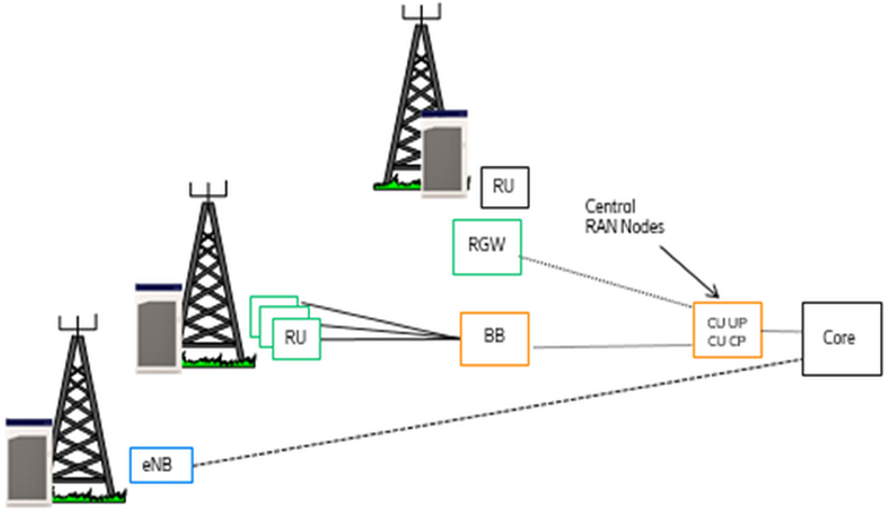
The requirements of 5G and 6G, compared to previous LTE mobile broadband network, pose strong demands on radio throughput and transmission latency. This could be easily achieved by employing an OFDM technique over air interface together with a more simplified network architecture [10,11]. Several gNodeB interconnected topologies have been proposed in order to simplify transmission network implementation and also to minimize expected IP packet transmission delays [10]. In IP/Ethernet gNodeB cloud-based star topology, the transmission equipment MAC scheduler packets are initially prioritized into different buffers and then transmitted over the IP LAN, following the well-known First–in First-out (FIFO) transmission technique, as shown in Figure 1.
In our proposed scheme, on the basis of the aforementioned analysis, the expected delay is split into two components; the first component considers the expected delay due to MAC scheduling priority of differentiated services with pre-emption vulnerabilities of pre-empted packets, whereas the second component considers the expected delay due to queue waiting transmission time in the transmission buffers.
This paper considers the most recent 5G and proposed 6G virtualized and cloud-based star topology, where lower layer gNodeBs are interconnected over a centralized gNodeB aggregator to forward IP packets to the EPC core network, as shown in Figure 1. An analytical solution is proposed to estimate the expected delay. Our scheme is based on Radio Resource Management (RRM) pre-emption queue priorities in order to estimate the IP/Ethernet MAC priority with pre-empted packets delay together with a queue loss model in order to estimate the expected delay of the packet transmission due to buffer FIFO and IP packet segmentations.
2. Scheduler Priority Queue
QoS flexible architecture in 5G network topology, as being standardized in the 5G gNodeB, exists to enable the core and the Radio Access Network subsystem (RAN) to differentiate service classes and services into high priority (pre-emption capable) and low priority (pre-emption vulnerable) [12,13,14], allowing network designers to define pre-emption strategies in the Radio Access Network (RAN) MAC layer to properly tune the scheduling functionality and support the demanding simultaneous request for high-throughput rates and low latency. Typical realistic examples might be the combination of enhanced mobile broadband (eMBB) services where throughput is the extremely important metric of the service, along with low-latency and reliable services (massive machine-type communications—mMTC) for Internet-of-Things (IoT) applications. Recent published works propose techniques that distinguish among priorities but have not considered the delay as a total of discrete components. A scheme akin to our paper’s contribution has been proposed by Sami Kekki et al. [15]. To the best of the authors’ knowledge, the scheme that approaches closer to our own proposal has been published by Tang [16,17]. These works feature resilient results on dynamic partitioning, however once more the pre-empted packets are given no further consideration on priority schemes (ARP), resulting in reduced packet service performance, and guaranteeing only priority traffic performance.
In our analysis, a queue management analysis is introduced along with an RRM algorithm based on capacity analysis and packet segmentation providing service differentiation from diverse applications. Performance metrics have been investigated considering a combined RRM, scheduling, and queue management approach without however considering dynamical buffer size or expected delay. Our proposed two-dimension queue model, analytically solved to calculate the expected IP pre-empted packet delay in the MAC/Ethernet scheduler, should be compliant with priority schemes investigating a more compact approach to multi-service implementation by considering pre-empted packet queue sizes through a general optimization process.
A pre-emptive priority mechanism is employed to guarantee the quality of service (QoS) requirement of service class p (pre-emption-capable service class, such as VoIP or video streaming services, URLLC, or mini-slot-based services) at the expense of some degradation of service class q (pre-empted vulnerable service class, such as enhanced mobile broadband eMBB FTP or WWW services), while the victim service class q buffer compensates the degradation. The solution of such a Markov queue is not trivial, on the contrary it can often become very complicated; however, our scheme adopts a mathematical solution based on an intuitive approach [18,19]. We have not considered any reservation or guard channels, since in the literature it has been proven that, for multi-service applications, guard channels may result in low utilization of the radio channels. Consequently, it is better for the network designers to follow parametric techniques such as dividing the radio channels into specific groups of radio blocks, thus following an intuitive resource sharing strategy between priority and non-priority services on user profiling or network capacity [20,21,22].
2.1. Model Description
We consider an IP-based multi-service network over LAN with two dominant service classes, p and q, respectively [23]. Service class p has a real-time rigid class with low-latency characteristics and strict delay constraints, high radio scheduling priority (high-priority scheme and pre-emption capability (high priority) attribute), and high DiffServ and Pbit priorities over IP-based transmission network. Service class q has mostly flexible bandwidth packet-switched characteristics with integrity and throughput constraint on errors rather than on delay, low Diffserv, and Pbit transmission priorities and pre-emption vulnerability (low priority) attributes. Already established service class q connections, mostly due to their bandwidth flexibility and delay in relaxing constraint conditions, can easily be pre-empted from service class p traffic in blocked conditions through appropriate Capacity Management (CM) and Flow Control Management (FCM) functionality performance as an overall performance enhancement. However, to preserve service class q QoS traffic metrics in pre-emptive conditions, a Q length buffer could be used to store service class q pre-empted packets for a specified (operator-determined) period of waiting time before they could be offered again as a service into an empty available resource or be permanently blocked and released.
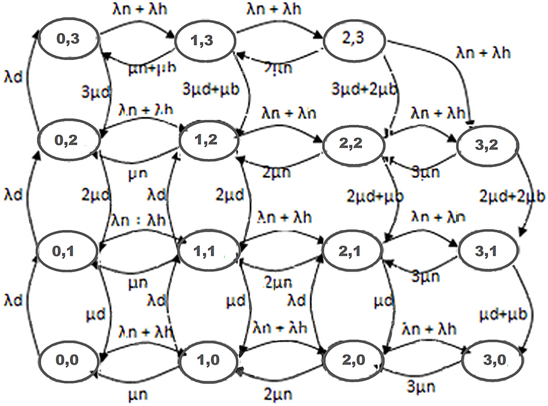
The analytical model Is based on a two-dimensional Markov chain with C available cell resources, where state (I, j) denotes specifically that there are i occupied resources from service class p users and j occupied resources from service class q users in the system. Without packet queue implementation it is always considered that , while when a finite queue buffer of size Q is considered for service class q, then . In this model, denotes the probability that the system is in state (i, j). It is also assumed that the arrival of p service requests follows Poisson arrival processes with rates for new services and for handoff services, while service class q requests follow the Poisson arrival process with rates . Moreover, p service times are assumed to be exponentially distributed with a mean of , while for service class q they are also considered to be exponentially distributed with a mean of .
2.2. q Service Class Buffer Delay Analysis
Since a queue buffer of finite size Q is considered in the cell, an additional performance metric, the impatience period of one service class q existing in the buffer, is also considered and it is assumed to be exponentially distributed with a mean . This impatience period is a threshold that defines the maximum time a pre-empted service class q IP packet should stay in the MAC/Ethernet queue buffer before either being served back into an empty resource or finally being blocked. State diagrams of such two-dimensional queue models with general C available resources and buffer queue size Q become really complicated to draw, hence without loss of generality and only for simplicity reasons we present, in Figure 2, a state diagram for a special case of cell total resources C = 3 and a general queue length Q = 2.
The state probabilities, following the proper two-dimensional steady-state analysis based on queueing theory principles, are calculated from the following recursive formula:
Also, considering the conditional probability and
Considering a flexible low-priority service class q request with queue buffer size Q, a new request-blocking probability is calculated by:
Regarding high-priority service class p requests, blocking probability is provided by
Additionally, considering the pre-emption case in our analysis, a new blocking probability is essential in order to describe the probability that a previously admitted service class q connection is blocked after it has been pre-empted by class p priority traffic. Consequently a class q connection already being served by the system in state will be blocked and rejected if (service class q connection has been pre-empted with probability a(i,j) and there was no idle position in the queue) (service class q connection has been pre-empted with probability a(i,j), obtains a position in the queue, but will never be served due to impatience time expiration with a probability .
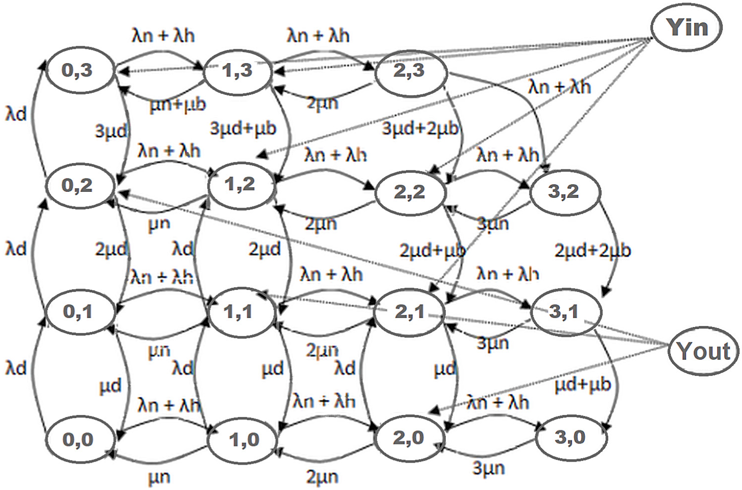
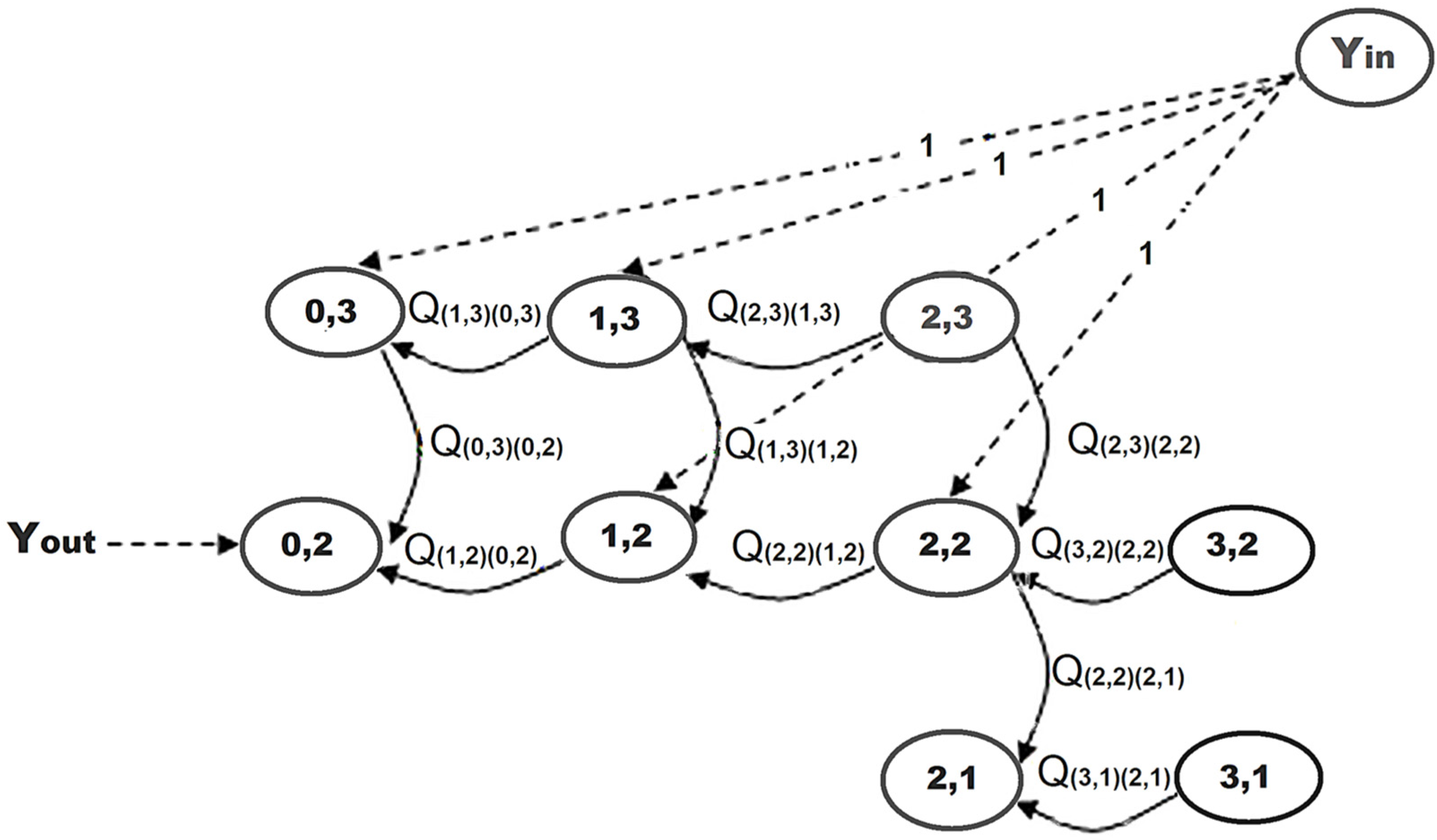
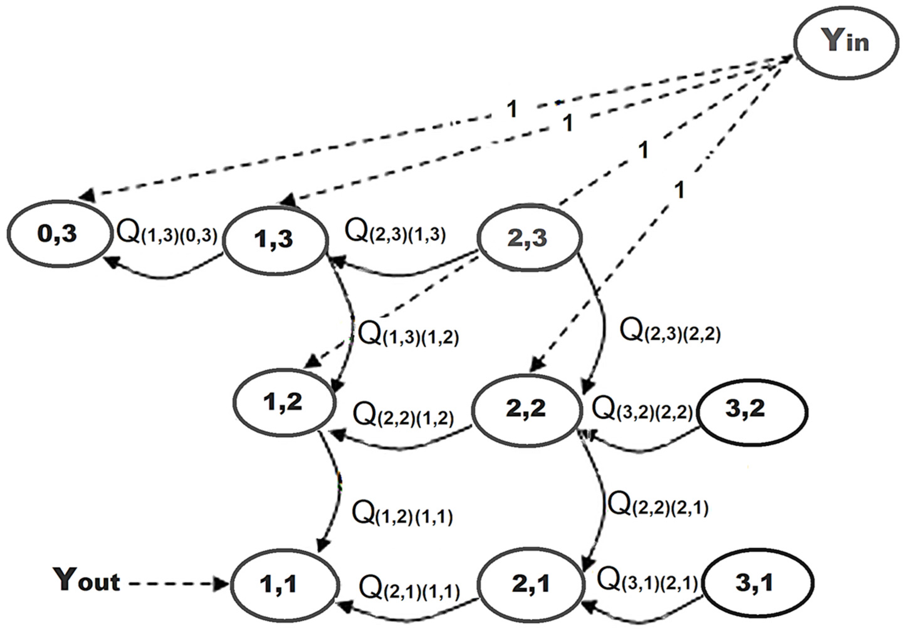
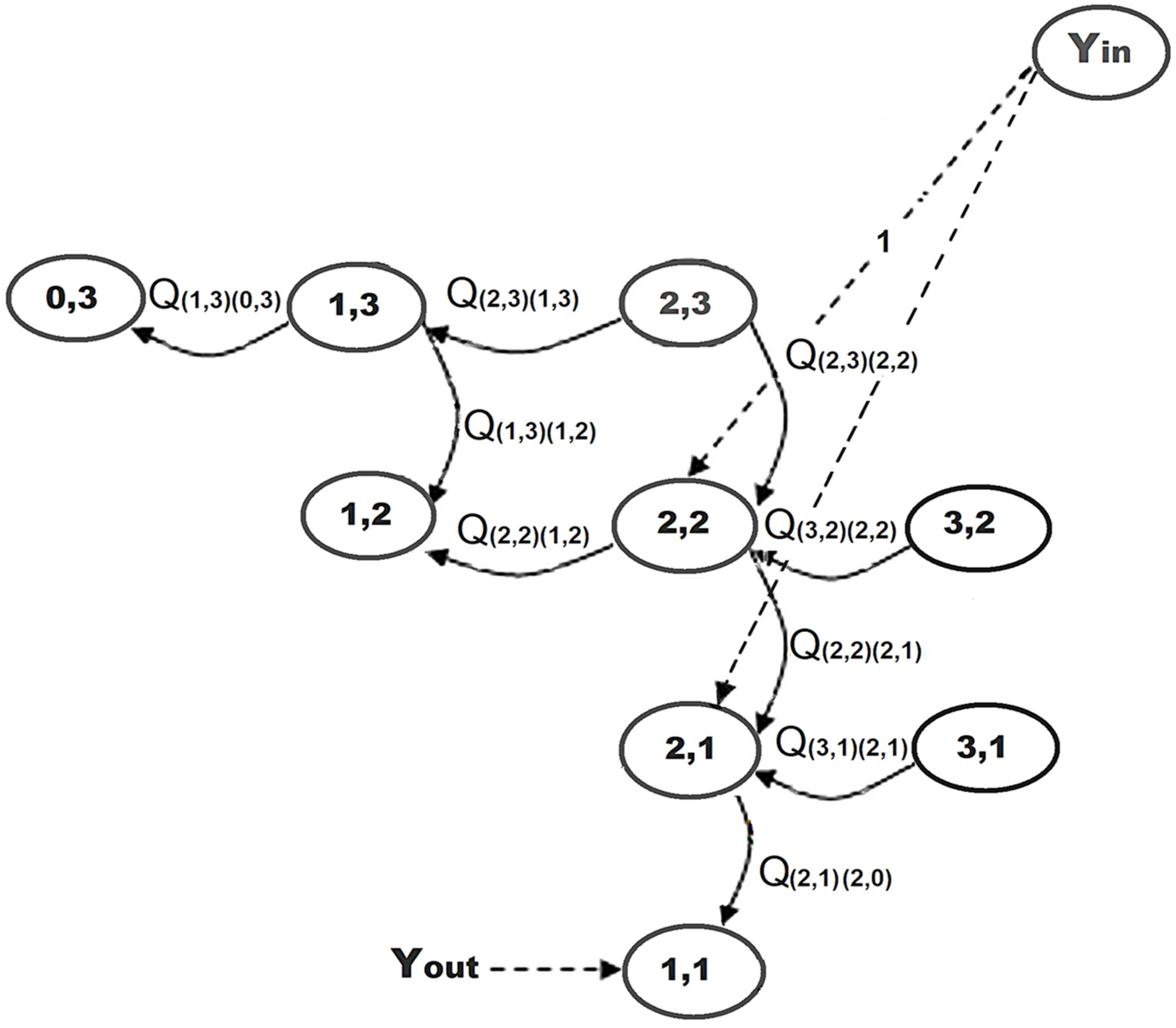
In order to analytically calculate this blocking probability, we consider the Markov queue as an input–output system with and sets of steady states. For the input set, we do consider the set of states that could accommodate one service class p request leading into pre-emption of one packet into the buffer, thus for total C = 3 resources and Q = 2 positions in the queue. Providing an example concerning the state (0,3) ∈ y_in the set will also clarify the same reasoning for the remaining states of the set. Indeed, state (0,3) means that the system serves zero class p services and three class q services; then, on receiving a new class p request, due to its priority over class q, one of the three (usually the latest arrived since the buffer is assumed to be FIFO) class q services on the buffer will be pre-empted and the system will end up into new state (1,3). On the contrary, since state (2,3) means that the system serves two class p services and three class q services; then, on receiving a new class p service, due to its priority over class q service, one of the three class q services on the buffer will not be pre-empted (the queue has only two positions) but it will be discarded and the system will end up into new state (3,2), that is (2,3) → (3,2). Due to the same reasoning, , due to capacity management (admission control), any new class p service will be immediately rejected since the maximum capacity resource C = 3 would be exceeded. On the other hand, the only allowed state transitions into set are (0,3) → (1,3) or (0,3) → (1,3) → (2,3) or (1,3) → (2,3) or (1,2) → (2,2) or (2,2) → (3,2) or (1,2) → (2,2) → (3,2) or (2,1) → (3,1).
Output set is the set of states where one previously pre-empted packet (pre-empted due to the acceptance of a new class p request in the system) has found a resource and has already been served, thus for total C = 3 resources and Q = 2 positions in the queue. As an example, state (0,2) meaning is that the system serves zero class p services and two class q services. The following output transitions are valid:
- (1,3) → (0,3) → (0,2). State (1,3) means one active class p service, two active class q services already in service, and one pre-empted class q service on queue. Then, with certain probability, before impatience time expires, the class p service is terminated, the pre-empted class q service obtains a free resource, and the system jumps into state (0,3), where three class q services are in service. Finally, one class q service is terminated, and the system jumps into state (0,2) as the output state.
- (2,3) → (1,3) → (0,3) → (0,2). State (2,3) means two active class p services, one active class q service already in service, and two pre-empted class q services on queue. Then, with certain probability, before the impatience time expires, one class p service is terminated, one pre-empted class q service obtains a free resource, and the system jumps into state (1,3), where now one active class p connection is in service, two active class q connections are already in service, and one pre-empted class q service exists on the queue. Then, with certain probability, before impatience time expires, the last class p service is terminated, the last pre-empted class q service obtains a free resource, and the system jumps into state (0,3), where three class q services are in service. Finally, one class q service is terminated, and the system jumps into state (0,2) as the output state.
- Any other path is forbidden since it must pass through state transitions (1,3) → (1,2) or (2,3) → (2,2).
In the previous statement, the state indicates any combination of class p and class q occupied resources leaving one extra system resource empty, which according to Figure 3 can be the states , , or . is defined as the sum of all possible transition probabilities from any possible state (i,j) into any possible state. Consequently, following previous analysis and generalizing the method to all possible transition cases, an existing class q service will be blocked based on the following blocking probability formula:
To calculate the probability, , we must calculate each transition probability separately. Calculations on transition probabilities could be facilitated by applying the following lemma:
Lemma:
transition probability could be calculated as [14]:
Proof of Lemma:
transition (2,2) → (1,2) is a feasible transition only when service time of traffic classes p is less than the minimum class q service time between in state (2,2) and the remaining patience time , that is:
□
However, for any arbitrary value of time t,
According to our initial considerations and based on the typical queueing theory assumptions, arrival and service times follow the respective exponential distributions and , where a is the mean service or arrival rate. Hence,
Since follows exponential distribution with mean rate in state (2,2), then
Additionally, the Lemma has been proven.
Based on this proof, all other transition probabilities can be calculated in the same way.
A more compact way to represent the calculation of is the use of a matrix representation technique, developed by Chen and Huaichen [15], which can replace the well-known Mason’s rule when many repetitive calculations must be executed.
where W is an N × 1 matrix with N states in the Markoff state model and S an N × 1 matrix declaring the transition probability from into any possible system state.
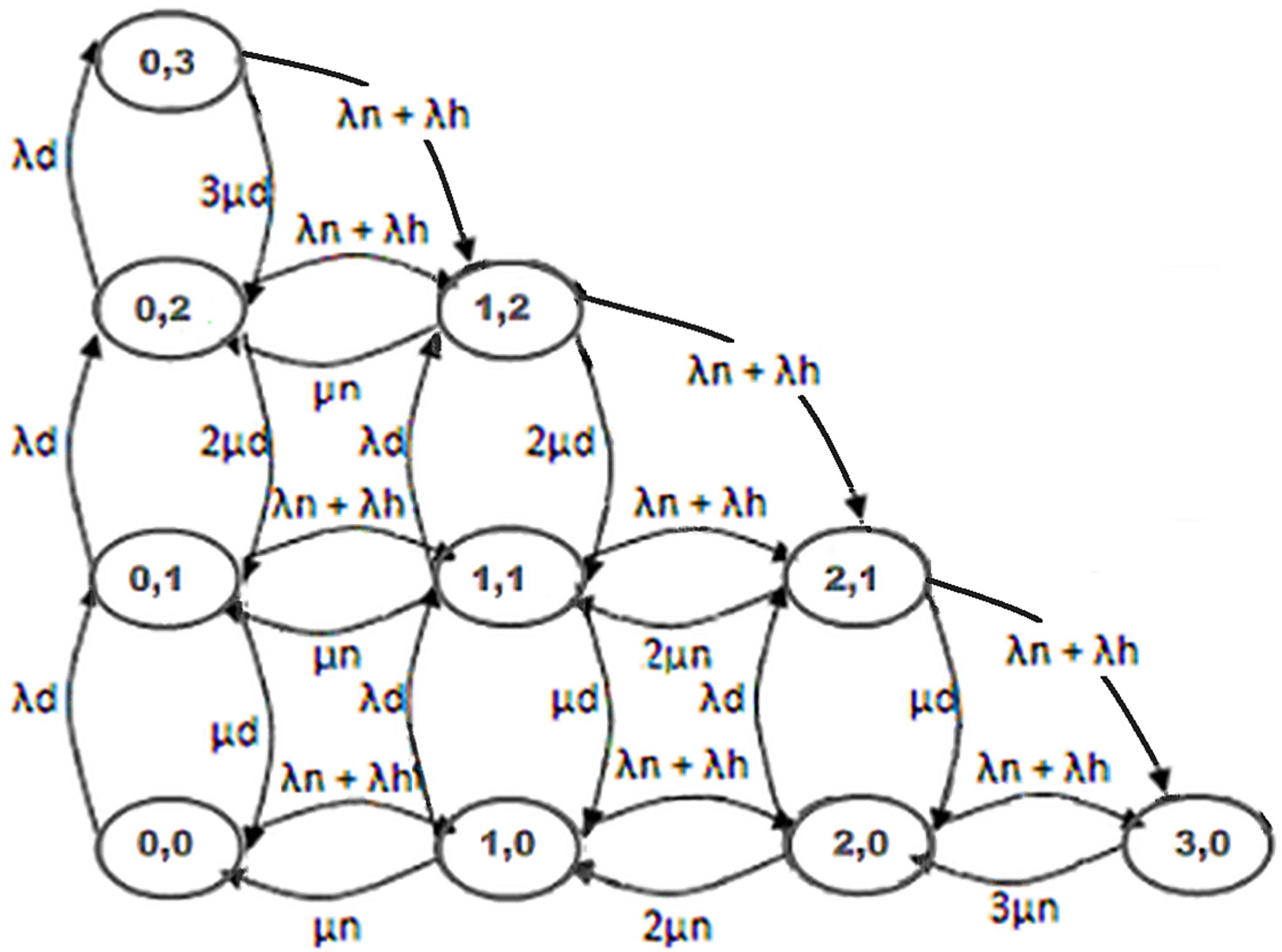
2.3. No Buffer Queue for Pre-Empted q-Type Services
If the queue length is zero (typical examples where in specific protocol payers there is not any buffer available) then the model is simplified as shown in Figure 7. Pre-emption probability of an already existing class q service into the system equals at least the sum of products with the transition probability . The transition probability is defined as , that is the probability that the system goes over from state to state . This could happen only if the arrival time of p requests is less than the class q serving time and less than the class p serving time in state , that is,
Following the same technique as in (5),
Therefore, the blocking probability of the class q connection previously being served, in the case of a model without queue, is calculated to be
together with the obvious restrictions
The blocking probability for a pre-empted class q connection in a system without queue is provided by
Considering these bounds, recalling Equation (4), it can be rewritten as
where is the maximum transition probability when the system has all channels occupied, whereas in all others states the case is . So, the blocking probability for a pre-empted packet in a system with queue implementation is calculated as
or
The waiting time of a queued pre-empted packet is defined as the time difference between the period of time an arbitrarily selected waiting packet spends in queue to the time it successfully accesses a free channel. The waiting time can be calculated using , which can be expressed as . Since is assumed to be exponentially distributed, can be obtained by . Consequently, the average scheduling waiting time of a queued pre-empted packet can be obtained by
3. Transmission Waiting Time FIFO Queue
After the pre-empted IP packet enters the buffer and waits for an average period of time, it has to leave the pre-emption buffer and enter the MAC/Ethernet transmission buffer, where other packets have already been scheduled in a FIFO sequence. In that phase, we must calculate the average delay time a packet spends on the transmission buffer before being transmitted over the LAN towards the EPC core.
3.1. Packet Segmentation Analysis
The 5G, and subsequently forthcoming 6G, packet transmission in Layer 2 Radio protocol stack (i.e., PDCP, RLC, MAC protocols) is based on IP packet formation [24,25]. According to 3GPP TS 36.321 standards, the packets to be transmitted all the way down from PDCP to the RLC and MAC layers are controlled by the MAC scheduler decision on the UE’s radio link quality. The MAC layer will inform RLC about the requested packet length (in bits) and the RLC will accommodate the PDCP IP packets from the proper buffer and apply segmentation functionality to fit them into the MAC request. As a general justified service statement, the average number of TCP/UDP IP bits per packet, MI, is considered for most applications to be 1500 bytes. Relying on 3GPP MAC layer uplink mapping, ⌈MI/Mmac⌉ could be estimated considering also that MAC payload carried in one slot during an uplink RB and scheduled in a Time Transmission Interval (TTI) will vary depending on the coding and modulation scheme selected from the Link Adaptation algorithm. The corresponding data rate at the MAC layer is defined precisely by 3GPP.
Let us consider then a TCP/UDP IP packet of MI variable bits per packet that is framed in such a way that the resulting MAC packets of variable length Mmac (bits per packet) contain a fixed number of Moverhead bits per packet [24]. In such a model, then, one MI packet will be segmented into MI/Mmac number of MAC packets. Considering that this division will rarely allocate an integer number, then one extra MAC packet will be needed in most of the cases to accommodate the remaining bits out of the division. The total number of transmitted bits then will be MI + ⌈MI/Mmac⌉Mover, where the factor ⌈MI/Mmac⌉Mover indicates the overhead created by the MAC layer for the MI size TCP/UDP IP packet transmission. Considering ideal radio channel conditions (no retransmissions), the expected whole TCP/UDP IP packet transmission time is
where is the number of transmitted bits per scheduled block (TTI duration varies accordingly in the discrete time domain range of (1 ms, 0.5 ms, 0.25 ms, 0.125 ms) based on the sub-carrier spacing (SCS) of the network configuration and bounded in the frequency domain in the fixed bandwidth of 180 kHz) which depends on the Link Adaptation Modulation Scheme, N is the average allocated number of 180 kHz radio block (RB) units of bandwidth per TTI considering also the constraint that 0 ≤ N ≤ BW where BW is the allocated configured bandwidth during cell planning (minimum 5 MHz up to maximum 100 MHz for sub6 GHZ or 400 MHz for mmW) and M is the number of antenna ports (in the case of MIMO implementation). In this analysis, then, and for average N 180 kHz-allocated RB, it is considered that (N ⋅⋅⋅ ) bits out of the total are transmitted simultaneously in a TTI scheduled interval. If spatial multiplexing (SMUX) of M × M in a typical massive MIMO (mMIMO) solution is also considered, then (M ⋯ N ⋯ ) bits are expected to be transmitted simultaneously in a scheduled TTI interval. Finally, ( ⋯ T) is the average non-scheduled period of time for the service, where is an integer value to indicate the average number of slots (Time Transmission Intervals) that one MAC service packet is not scheduled by the scheduler in a total scheduling period T. Remember that for downlink scheduling decisions depends mainly on the QoS Guaranteed Bit Rate (average) GBR parameter, on Channel Quality Index CQI measurement report, and also on UE transmitter mean-packet waiting time on the buffer.
The average transmission delay is expected to be increased due to MAC HARQ retransmission functionality [25]. MAC retransmissions are created (up to a maximum configured number known as maxHARQretransmit) when errors are present and detected in the CRC error detection decoding procedure in the received packets and the total resulting BER is higher than a threshold based on the QoS profile of the supported service [14]. In this analysis the corrupted packets are considered to be uncorrelated (a very good and well justified approximation considering radio channels with short time and frequency coherency response), hence if one received MAC transport block packet is found to be faulty based on BLER and retransmission is requested, the next received MAC transport block packet could either be found faulty or not, without any prior memory of the previously transmitted MAC packet. Assuming that each MAC packet can be retransmitted v times at most, and the average number of retransmissions is nmac, TCP/IP packet transmission delay time is recalculated as [24]
where the average number of retransmissions nmac is a function of the MAC packet error rate and it is calculated as [24]
where is the average bit error probability of the MAC bits which further depends on the channel conditions (i.e., CQI reports and SINR planned area) and is necessary for the computation of the average number of retransmissions nmac.
3.2. Packet Transmission Analysis
We do consider a generalized queue system with one single server, m channels (resources) in parallel [26], finite queue transmission length, Poisson λ process arrivals, and independent and uniform service time distributed on [0, s], s > 0. Transit time effects are ignored in this analysis, and the reasoning behind uniform distributed service time is the really small scheduling delay for every IP MAC packet in the queue, following the strict requirements on 5G transmission, Pbit priority scheduling delays, and performing average uniform service time distribution. For equilibrium in the queueing solution, we do suppose that m > λ. Define , the probability of existing specifically n IP MAC packets in both queue and service at a given time, τ, and the probability that no more than n packets exists in the model at a given time τ. Further in our analysis the probability in the unit of time specifically zero packets exist in the queue and m packets in service could be calculated as the intersection of (the probability that no more than zero packets exist in the queue as long as m packets exist in the server at the beginning of unit of time) and (the probability (Poisson distribution) of zero arrivals during the considered time interval), that is,
Along the same lines, the probability that specifically one packets exists in the queue at the unit of time can be calculated as the union of (the intersection of (the probability that no more than zero packets exist in the model as long as m packets exist in the server at the beginning of unit of time) and (the probability (Poisson distribution) of one arrival during that interval )) and (intersection of (the probability that exactly one packet exists in the queue and m packets are in service at the beginning of unit of time) and (the probability (Poisson distribution) of zero arrivals during that interval)):
Considering the general case, the overall probability that specifically n packets exist in the system at the unit of time equals
To calculate, then, the probability in the above general formula, we proceed with Laurent series expansion as follows:
Following the summations and after appropriate mathematical calculations we simplify (18) into
where using Laurent power series definition we define the generating function and by definition of finite Laurent series . Since , complex function is a regular function bounded into the unit circle on the complex space . Numerator consists of two polynomials of mth order. Both and are analytical functions inside the simple curve and also bounded into the unit circle on the complex space . Since on , then both have same number of zeroes inside , and since they are polynomials of mth order they have m zeroes inside, , denoted as , respectively, leading into a closed-form function of which can be written as
Since z = 1 is one of the roots, the numerator is
Furthermore, in (20) factor A is a constant calculated from the total probability condition
Finally, using the Laurent series
The expansion of the right part of the previous equation into the Laurent series around z = 0 is essential in order to calculate πn. , we assign the coefficients of after the expansion is performed. Considering the case of m = 1 (MAC/Ethernet transmission scheduler considers each packet as a unique service input), the numerator is simplified into a first-order polynomial with one single real root.
The polynomial expansion coefficients, after expanding the polynomial into Laurent series around z = 0, become
From the expansion, the general term is calculated
Additionally, average expected packet buffer delay is calculated as
Finally, the total pre-empted packet transmission delay equals
The total prioritized packet transmission delay equals
4. Conclusions
The findings presented in this work touch upon topics that have been certainly discussed with relation to 5G resilience [27]. Our contribution relies in the direct calculation of delay as a sum of two discrete components based on different conditions during the transmission of TCP/IP packets, a novel feature in the literature. The applicability of this innovative scheme ranges in many of the current 5G paradigms such as smart health systems [28], services oriented towards smart cities [29], the implementation of remote digital control for Industry 4.0 [30], and the Internet-of-Ships [31]. These use cases require specific constraints in terms of average packet delay as per URLLC [32], while demanding cloud-based architectures [33].
The strict preservation of URLLC requirements as well as the restriction (upper-bound) of transmission delay, even when URLLC requirements do not apply, is a fundamental pilar of QoS [34,35,36,37,38], as per ITU specifications [39,40,41]. The satisfaction of such QoS provisions is not merely desired from a technical standpoint, but also from the perspective of user experience, as show in [42], assessing the QoE on the basis of 5G-enabled broadband services with an upper-bound on latency.
All such provisions and requirements are certain to be even stricter within the context of Beyond-5G/6G designation [43], with the shift towards higher spectrum (i.e., mmW bands) and therefore more available bandwidth for ultra-wideband beamforming and higher-order modulation [44]. Therefore, our contribution aspires to address challenges not only within present-day microwave-driven 5G, but also for the upcoming challenges of the mm-wave/THz and beyond bands.
Some future extension to our contribution might be the comparison of our QoS approach with the proposed general methodology and model in the excellent book chapter in [45]. This might be useful in order to evaluate different QoSs and queue metrics and try to enhance the overall modeling. Moreover, in addition to our static analysis of pre-configured QoS settings in the network, a dynamic QoS configuration could be another interesting approach, especially in the evolving cloud-based RAN architectures. This dynamic QoS configuration has been proposed in [45] through dynamic queue management that implies the ability to dynamically change queues’ parameter configurations according to the requirements specified through the slice orchestration on the application layer. However, what is missing is the analysis of different queues on different parts of the network infrastructure, as has been proposed and tackled in our contribution.
Author Contributions
Conceptualization, S.L. and M.P.; methodology, S.L., M.P. and T.C.; validation, M.P. and T.C.; formal analysis, S.L., M.P. and T.C.; investigation, S.L., M.P. and T.C.; resources, M.P. and T.C.; data curation, M.P. and T.C.; writing—original draft preparation, S.L.; writing—review and editing, M.P. and T.C.; visualization, M.P. and T.C.; supervision, S.L. and M.P.; project administration, T.C. All authors have read and agreed to the published version of the manuscript.
Funding
This research received no external funding.
Institutional Review Board Statement
Excluded.
Informed Consent Statement
Not relevant.
Data Availability Statement
Not relevant.
Conflicts of Interest
The authors declare no conflict of interest.
References
- 5G Vision and Requirements; Report; Report type: Online resource; IMT-2020 (5G) Promotion Group: Beijing, China, 2014; Available online: https://www.itu.int/dms_pub/itu-r/oth/0a/06/R0A0600005D0001PDFE.pdf (accessed on 23 April 2022).
- 3GPP TS 23.060; V.15.5.0 General Packet Radio Service (GPRS) Service Description Stage 2 (Release 15). 3GPP: Sophia-Antipolis, France, 2018.
- ETSI 3G TS 22.071; V.4.0.0 Location Service (LCS) Service Description, Stage 1. TSG-SA Working Group 1 (Services) Meeting #8: Beijing, China, 10–14 April 2000.
- 3GPP TS 23.107; V.5.10.0 Release 5; Quality of Service (QoS) Concept and Architecture. ETSI: Sophia-Antipolis, France, 2003.
- 3GPP TS 29.212; “Policy and Charging Control over Gx Reference Point”, Technical Specification Group Core Network & Terminals. v8.8.0. ETSI: Sophia-Antipolis, France, 2014.
- Liu, G.; Li, N.; Deng, J.; Wang, Y.; Sun, J.; Huang, Y. The SOLIDS 6G Mobile Network Architecture: Driving Forces, Features, and Functional Topology. Engineering 2021, 8, 42–59. [Google Scholar] [CrossRef]
- Saad, W.; Bennis, M.; Chen, M. A Vision of 6G Wireless Systems: Applications, Trends, Technologies, and Open Research Problems. IEEE Netw. 2019, 34, 134–142. [Google Scholar] [CrossRef] [Green Version]
- You, X.; Wang, C.-X.; Huang, J.; Gao, X.; Zhang, Z.; Wang, M.; Huang, Y.; Zhang, C.; Jiang, Y.; Wang, J.; et al. Towards 6G wireless communication networks: Vision, enabling technologies, and new paradigm shifts. Sci. China Inf. Sci. 2021, 64, 110301. [Google Scholar] [CrossRef]
- Viswanathan, H.; Mogensen, P.E. Communications in the 6G Era. IEEE Access 2020, 8, 57063–57074. [Google Scholar] [CrossRef]
- 3GPP TR 25.913; Feasibility Study of Evolved UTRA and UTRAN. ETSI: Sophia-Antipolis, France, 2009.
- Dahlman, E.; Parkvall, S.; Skold, J.; Beming, P. 3G Evolution: HSPA and LTE for Mobile Broadband; Academic Press: Oxford, UK, 2007. [Google Scholar]
- 3GPP TS 25.104; Base Station (BS) Radio Transmission and Reception (FDD). ETSI: Sophia-Antipolis, France, 2018.
- Pokhariyal, A.; Kolding, T.; Mogensen, P.E. Performance of Downlink Frequency Domain Packet Scheduling for the UTRAN Long Term Evolution. In Proceedings of the 2006 IEEE 17th International Symposium on Personal, Indoor and Mobile Radio Communications, Helsinki, Finland, 11–14 September 2006; pp. 1–5. [Google Scholar] [CrossRef]
- 3GPP TS 23.503; v15.6.0 Release 15; Policy and Charging Control Framework for the 5G System (5GS) Stage 2. 3GPP: Sophia-Antipolis, France, 2019.
- Kekki, S.; Featherstone, W.; Fang, Y.; Kuure, P.; Li, A.; Ranjan, A.; Purkayastha, D.; Jiangping, F.; Frydman, D.; Verin, G.; et al. MEC in 5G networks. ETSI White Pap. 2018, 28, 1–28. [Google Scholar]
- Tang, S.; Li, W. Performance analysis of a channel allocation scheme for multi-service mobile cellular networks. Int. J. Commun. Syst. 2007, 20, 177–205. [Google Scholar] [CrossRef]
- Tang, S.; Li, W.; Kim, J. Modeling adaptive bandwidth allocation scheme for multi-service wireless cellular networks. In Proceedings of the IEEE International Conference on Wireless And Mobile Computing, Networking And Communications, Montreal, QC, Canada, 22–24 August 2005; Volume 2, pp. 189–195. [Google Scholar]
- Chang, C.-J.; Su, T.-T.; Chiang, Y.-Y. Analysis of a cutoff priority cellular radio system with finite queueing and reneging/dropping. IEEE/ACM Trans. Netw. 1994, 2, 166–175. [Google Scholar] [CrossRef]
- Chen, H. The Matrix Expression of Signal Flow Graph and Its Application in System Analysis Software. Chin. J. Electron. 2002, 11, 361–363. [Google Scholar]
- Vardakas, J.S.; Kartsakli, E.; Papaioannou, S.; Kalfas, G.; Pleros, N.; Antonopoulos, A.; Verikoukis, C. Quality of Service Provisioning in High-Capacity 5G Fronthaul/Backhaul Networks. In Interactive Mobile Communication Technologies and Learning; Auer, M., Tsiatsos, T., Eds.; IMCL 2017; Advances in Intelligent Systems and Computing; Springer: Cham, Switzerland, 2018; Volume 725. [Google Scholar] [CrossRef]
- Perveen, A.; Abozariba, R.; Patwary, M.; Aneiba, A. Dynamic traffic forecasting and fuzzy-based optimized admission control in federated 5G-open RAN networks. Neural Comput. Appl. 2021, 1–19. [Google Scholar] [CrossRef]
- Krummacker, D.; Veith, B.; Lindenschmitt, D.; Schotten, H.D. Radio Resource Sharing in 6G Private Networks: Trustworthy Spectrum Allocation for Coexistence through DLT as Core Function. Proj. Open6GHub 2022, 1–8. [Google Scholar] [CrossRef]
- Spiros, L. Topology Dependant IP Packet Transmission Delay on LTE Networks. In Proceedings of the Selected Papers of the 2014 International Conference on Topology and its Applications, Nafpaktos, Greece, 3–7 July 2014; pp. 122–138. [Google Scholar]
- Louvros, S.; Iossifides, A.C.; Aggelis, K.; Baltagiannis, A.; Economou, G. A Semi-Analytical Macroscopic MAC Layer Model for LTE Uplink. In Proceedings of the 2012 5th International Conference on New Technologies, Mobility and Security (NTMS), Istanbul, Turkey, 7–10 May 2012; pp. 1–5. [Google Scholar] [CrossRef]
- 3GPP TS 38.321; Evolved Universal Terrestrial Radio Access (E-UTRA); Medium Access Control (MAC) Protocol Specification (Release 8). V16.1.0. ETSI: Sophia-Antipolis, France, 2020.
- Louvros, S.; Paraskevas, M. Analytical average throughput and delay estimations for LTE uplink cell edge users. Comput. Electr. Eng. 2014, 40, 1552–1563. [Google Scholar] [CrossRef]
- Grieco, L.A.; Boggia, G.; Piro, G.; Jararweh, Y.; Campolo, C. Ad-hoc, mobile, and wireless networks. In Proceedings of the 19th International Conference on Ad-Hoc Networks and Wireless, ADHOC-NOW, Bari, Italy, 19–21 October 2020; pp. 19–21. [Google Scholar]
- Lloret, J.; Parra, L.; Taha, M.; Tomás, J. An architecture and protocol for smart continuous eHealth monitoring using 5G. Comput. Netw. 2017, 129, 340–351. [Google Scholar] [CrossRef]
- Yang, C.; Liang, P.; Fu, L.; Cui, G.; Huang, F.; Teng, F.; Bangash, Y.A. Using 5G in smart cities: A systematic mapping study. Intell. Syst. Appl. 2022, 14, 200065. [Google Scholar] [CrossRef]
- Mourtzis, D.; Angelopoulos, J.; Panopoulos, N. Smart Manufacturing and Tactile Internet Based on 5G in Industry 4.0: Challenges, Applications and New Trends. Electronics 2021, 10, 3175. [Google Scholar] [CrossRef]
- Aslam, S.; Michaelides, M.P.; Herodotou, H. Internet of Ships: A Survey on Architectures, Emerging Applications, and Challenges. IEEE Internet Things J. 2020, 7, 9714–9727. [Google Scholar] [CrossRef]
- Anand, A.; De Veciana, G.; Shakkottai, S. Joint scheduling of URLLC and eMBB traffic in 5G wireless net-works. IEEE/ACM Trans. Netw. 2020, 28, 477–490. [Google Scholar] [CrossRef] [Green Version]
- Ford, R.; Sridharan, A.; Margolies, R.; Jana, R.; Rangan, S. Provisioning low latency, resilient mobile edge clouds for 5G. In Proceedings of the 2017 IEEE Conference on Computer Communications Workshops (INFOCOM WKSHPS), Atlanta, GA, USA, 1–4 May 2017; IEEE: Minato City, Tokyo, 2017; pp. 169–174. [Google Scholar]
- Wan, L.; Anthony, C.K.S.; Liu, J.; Wu, Y.; Brain, C.; Xiao, W.; David, M.; Zhao, Y.; Saboorian, T. 5G System Design; Springer International Publishing: Cham, Switzerland, 2021. [Google Scholar]
- Marsch, P.; Bulakci, O.; Queseth, O.; Boldi, M. 5G System Design; Wiley: New York, NY, USA, 2018. [Google Scholar]
- Bin Zikria, Y.; Kim, S.W.; Afzal, M.K.; Wang, H.; Rehmani, M.H. 5G Mobile Services and Scenarios: Challenges and Solutions. Sustainability 2018, 10, 3626. [Google Scholar] [CrossRef] [Green Version]
- Siddiqi, M.A.; Yu, H.; Joung, J. 5G Ultra-Reliable Low-Latency Communication Implementation Challenges and Operational Issues with IoT Devices. Electronics 2019, 8, 981. [Google Scholar] [CrossRef] [Green Version]
- Available online: https://www.itu.int/rec/T-REC-E.800SerSup9/en (accessed on 3 September 2022).
- Available online: https://www.itu.int/pub/T-TUT-QOS-2022-1 (accessed on 5 September 2022).
- Available online: https://www.itu.int/rec/T-REC-P.10-201711-I (accessed on 2 October 2022).
- Andriyanto, F.; Muhammad, S. The QoE assessment model for 5G mobile technology. In Proceedings of the 2017 International Conference on Broadband Communication, Wireless Sensors and Powering (BCWSP), Jakarta, Indonesia, 21–23 November 2017; IEEE: Minato City, Tokyo, 2017. [Google Scholar]
- Li, R.; Decocq, B.; Barros, A.; Fang, Y.; Zeng, Z. Petri net-based model for 5g and beyond networks resilience evaluation. In Proceedings of the 2022 25th Conference on Innovation in Clouds, Internet and Networks (ICIN), Paris, France, 7–10 March 2022; IEEE: Minato City, Tokyo, 2022; pp. 131–135. [Google Scholar]
- Paul, B.; Sertel, K.; Nahar, N.K. Photonic Beamforming for 5G and Beyond: A Review of True Time Delay Devices Enabling Ultra-Wideband Beamforming for mmWave Communications. IEEE Access 2022, 10, 75513–75526. [Google Scholar] [CrossRef]
- Poryazov. Methods for Modelling of Overall Telecommunication Systems. In Research in Computer Science in the Bulgarian Academy of Sciences; Atanassov, K.T., Ed.; Studies in Computational Intelligence; Springer: Cham, Switzerland, 2021; Volume 934. [Google Scholar]
- Bojović, P.D.; Malbašić, T.; Vujošević, D.; Martić, G.; Bojović, Ž. Dynamic QoS Management for a Flexible 5G/6G Network Core: A Step toward a Higher Programmability. Sensors 2022, 22, 2849. [Google Scholar] [CrossRef] [PubMed]
Figure 1.
gNodeB star topology implementation in 5G/6G cloud-based transmission network.

Figure 2.
Two-dimensional Markov chain for mixed traffic services with packet queue.

Figure 3.
The state diagram with queue to calculate .

Figure 4.
First case of transition from states (0,3) or (1,3) or (1,2) or (2,2) into state (0,2).

Figure 5.
Second case of transition from states (1,3) or (2,3) or (1,2) or (2,2) or (2,1) into state (1,1).
Figure 5.
Second case of transition from states (1,3) or (2,3) or (1,2) or (2,2) or (2,1) into state (1,1).

Figure 6.
Third case of transition from states (2,2) or (2,1) into state (2,0).

Figure 7.
The state diagram (two-dimensional Markov chain) for GSM/GPRS traffic without queue.

Disclaimer/Publisher’s Note: The statements, opinions and data contained in all publications are solely those of the individual author(s) and contributor(s) and not of MDPI and/or the editor(s). MDPI and/or the editor(s) disclaim responsibility for any injury to people or property resulting from any ideas, methods, instructions or products referred to in the content. |
© 2023 by the authors. Licensee MDPI, Basel, Switzerland. This article is an open access article distributed under the terms and conditions of the Creative Commons Attribution (CC BY) license (https://creativecommons.org/licenses/by/4.0/).
Share and Cite
MDPI and ACS Style
Louvros, S.; Paraskevas, M.; Chrysikos, T. QoS-Aware Resource Management in 5G and 6G Cloud-Based Architectures with Priorities. Information 2023, 14, 175. https://doi.org/10.3390/info14030175
AMA Style
Louvros S, Paraskevas M, Chrysikos T. QoS-Aware Resource Management in 5G and 6G Cloud-Based Architectures with Priorities. Information. 2023; 14(3):175. https://doi.org/10.3390/info14030175
Chicago/Turabian StyleLouvros, Spiros (Spyridon), Michael Paraskevas, and Theofilos Chrysikos. 2023. "QoS-Aware Resource Management in 5G and 6G Cloud-Based Architectures with Priorities" Information 14, no. 3: 175. https://doi.org/10.3390/info14030175
Note that from the first issue of 2016, this journal uses article numbers instead of page numbers. See further details here.