1. Introduction
Watercraft, submersibles, offshore structures, and other marine structural components are exposed to relevant environmental challenges. Therefore, materials exhibiting elevated resistance and requiring few or no maintenance for extended periods of time are generally under consideration. Additionally, being lightweight and corrosion resistance are mandatory for vessels, to meet design requirements and perform with speed and unfailing reliability. Composite materials, with specific reference to fiber-reinforced polymers (FRP), have been extensively incorporated in the marine industry following their early applications after World War II when composites were designed to overcome corrosion issues experienced with steel, aluminum, and wood. Weight reduction was, and remains, a key aspect, particularly for topside weight found in commercial vessels. Over the years, composites have been developed to meet the growing and variable demand coming from the marine sector, still preserving a relevant usage for manufacturing of consolidated elements, including gratings, ducts, shafts, piping, and hull shells. To date, composites are employed in all areas of the marine sector and for a variety of components and structures, namely hulls, bearings, propellers, hatch covers, exhausts, topside structures, radomes, sonar domes, railings, vessels of all types, valves and other subsea structures. In recent years, racing powerboats made of composites are becoming more and more common for long-lasting high performance and safety.
Salt and corrosive seawater are especially damaging to watercraft and structures. Given the capability of composites to resist corrosion and fatigue, maintenance requirements can be significantly reduced by using thermoset composites in specific components, such as fixings and connectors. The usage of thermoset resins as matrix material is typically associated with:
the strength-to-weight ratio for lighter-weight durability,
dimensional stability for lasting performance,
corrosion resistance for deterioration-free operation,
lighter weight to reduce operating costs and improve efficiency,
possibility to combine multiple parts into one and reduced maintenance,
sound baffling for a less noisy operating environment,
design flexibility for use in complex shapes,
high levels of acoustic transparency for radomes and sonar domes,
enhanced stiffness for stability.
Composites science and technology are developing rapidly, providing new material solutions, addressing the requirement for high performance. In the next sections, the latest developments in this area are reviewed. The keywords used in the literature search are the following: (i) advanced composite materials, (ii) hybrid composite materials, (iii) glass fiber reinforcement plastic (GFRP), (iv) carbon fiber reinforcement plastic (CFRP), (v) aramid fiber reinforcement plastic (AFRP), (vi) lightest marine structure, (vii) marine renewable energy, (viii) tidal turbines, (ix) wind turbines, (x) underwater construction, (xi) Repair. The databases used in the review process are the following: (i) American Society of Civil Engineering (ASCE) Library, (ii) ScienceDirect, (iii) Springer, (iv) Google Patents search engine, University of Washington (UW) Departments Web Server, (v) The American Society of Mechanical Engineers (ASME) Digital Collection, (vi) University of Southern Queensland Web Server, (vii) Cambridge University Press, (viii) Taylor and Francis Online, (ix) University of South Florida Web Server, (x) OnePetro Online Library, (xi) International Journal of Recent Trends in Engineering, (xii) MIT Digital Repository, (xiii) SAGE Publishing, (xiv) United States Department of Energy—Office of Energy Efficiency and Renewable Energy Web Server, (xv) IOP Science Publishing, (xvi) IEEE Xplore Digital Library, (xvii) Composite Repair Users Group Web Server, (xviii) The Royal Society Publishing.
2. Application of Composite Materials for Hulls, Ships, and Submarines
The nautical industry has experienced an evident technological evolution and, today, the manufacturing of hulls is based on latest-generation production systems. The introduction of advanced composite materials represented a milestone innovation in the manufacturing of boats and vessels. Composite technology has allowed manufacturers to improve the quality of products obtaining stiff and light structures, with benefits in terms of sailing performances and working life. In addition, thanks to the possibility to automatize and speed up manufacturing procedures, the adoption of composite materials have lowered the overall costs making the end product affordable to a wider public [
1,
2,
3]. Stiffer hulls and decks are the main applications where the shipbuilding industry has adopted composite sandwich structures, composed by two skins with high stiffness and strength placed on the external faces of a component and by a soft and thick core. Stiff skins provide high bending stiffness, meanwhile, the core supports the shear and compressive stresses and stabilizes the skins preventing global and local instabilities. The weight reduction results in larger cargo capacity, fuel-saving, lower inertia, and increased ship stability and buoyancy. In addition, FRPs show satisfactory corrosion resistance in the marine environment and require less maintenance. In marine sandwich structures, aramid, carbon and glass FRP materials are commonly used as skins instead of metals. Polymeric foams (i.e., polystyrene and polyvinyl chloride (PVC)) and honeycomb are mainly used as core material. The combination of aramid fibers (such as Kevlar) or carbon to reinforce high-quality resins and ultra-light cores (such as Nomex), results in boats with unmatched mechanical properties and dimensions. On the other hand, composite sandwich structures have a higher cost compared to conventional materials and the manufacturing processes are more labor-intensive, limiting their widespread use [
1,
4].
2.1. Naval Applications
2.1.1. Military Applications
The first application of glass-reinforced plastic (GRP) for naval shipbuilding is dated back to 1973 with the mine-countermeasures vessels (MCMVs) HMS Wilton, characterized by a length of 60 m and a full load of 725 tons. It was realized by the Vosper-Thornycroft company and mass-produced by the British Navy since 1975. The GRP ship proved to be able to withstand the extreme working conditions in the Ocean as well as impacts and fires [
5].
The subsequent ’Sandown’ class project of the United Kingdom Navy aimed to reduce both the weight for a greater weapon capacity and the costs, to improve the international competitiveness of the project. Oversized components were redesigned (acceptably reducing safety margins) still preserving acceptable reliability. Furthermore, bolts between frames and hull were removed. In 1975, an R&D program was jointly launched by France, Belgium, and the Netherlands to build 40 ships, providing a technology sharing by the involved countries. In particular, main machinery machines, auxiliary machines, and weapon equipment were realized by Dutch, Belgian and French companies, respectively [
5]. The DCN Diving company provided the technologies for shipbuilding using GRP for hulls, decks and partitions, pins to join the hull and the reinforcements. Sandwich structures consisting of GRP skins with a PVC foam core were used in GRP MCMVs developed by Karlskrona shipyard in Sweden between 1970 and 1984. The technical solution allowed in meeting the requirements of fatigue resistance, non-magnetic behavior, and economic and technical feasibility. Other examples are the production of catamaran hull for MCMV using sandwiches (foam-based core and GRP skin) by the Royal Australian Navy. The hull of the HMAS Rushcutter was realized using a 60 mm thick high-density PVC foam core and 8 mm thick GRP. More specifically, the skin panels were manufactured combining chopped strand mat and woven roving reinforcements, in order to maximize the bond strength, fire resistance, and interlaminar shear strength.
Figure 1 reports the evolution over the years of the length of ships entirely produced using composite materials for the main three classes of vessels [
5,
6].
The corvettes are the longest ships currently built-in FRP. In this segment, the multipurpose Visby corvettes, designed and realized in the framework of the YS-2000 project by the Swedish Navy, is an excellent example of composite material application. With a length of 72 m, a width of 10.4 m and a full load of 620 tons, Visby was one of the largest ships in the fleet. It was designed for surveillance, combat, minesweeper, countermeasures and anti-submarine war operations. The Visby corvette was designed entirely in composite materials using sandwich panels with carbon and glass reinforcement and vinyl resin matrix. Indeed, composite materials provided robustness, resistance to underwater shock loads and low magnetic capacities combined with lightweight nature. Visby was the first ship with a significant content of carbon fiber composites within the hull. Although the cost of carbon fibers was at least five times higher than that of glass limiting their use in large naval structures, it was found that by using some carbon fibers in the composite, beside the adequate electromagnetic shielding, the weight of the hull was reduced by about 30%, without significantly increasing the manufacturing cost. The achieved weight-saving translated into a reduction in fuel consumption [
2,
5,
7].
The Royal Singapore Navy and Sweden Kockums AB shipyards designed a new generation of corvette patrol, known as the New Generation Patrol Vessel (NGPV) class, made of FRP. The designed ship is 80 m long with a full load weight of 1016 tons. Technological developments in the design and manufacturing of composites have led to a steady increase of the lengths of the ship and currently, there are fully composite ships up to 80/90 m in length. Recent studies forecasted that hulls of medium-sized warships, entirely made of composite materials, could easily reach a length of 120/160 m in 2020 [
4]. However, traditional materials (aluminum and steel) still remain the main choice for corvettes due to reduced manufacturing costs and higher reliability [
8].
The United States Navy first introduced a fairwater entirely made of GRPs on the conning tower of a “Guppy” class submarine. These parts, traditionally made of aluminum, undergo severe corrosion and require continuous ongoing maintenance and repairs. The composite ones resulted in more durable requiring reduced maintenance. As a result, more than 25 Guppy class submarines were equipped with composite structures between 1950 and 1970. Composite materials are also considered for internal applications within a pressurized submarine, including bulkheads, decks, hatches, main propulsion shaft, ballast tanks, tanks, machines, pumps, valves and piping [
4].
Figure 2 summarizes the applications on military ships and submarines where the composite materials are currently employed or under development [
1,
5,
6].
2.1.2. Civil Applications
Apart from combat ships, high-performance materials are now applied also in civil sectors. GRPs are worldwide used to produce vessels of fishing boats, small boats, hovercraft, and catamarans. Japan is by far the leading country in terms of the number of active GRP vessels. In 1984, Japanese GRP fishing boats represented 60% of the total registered vessels, including some hulls up to 45 m in length. Apart from Japan, large GRP fishing boats have been produced also in European and Australian shipyards [
1,
5,
6].
The applications GRP for small boats include yachts, sailboats, barges, and lifeboats. GRP is the predominantly used material representing approximately 80% of the hulls, for ships long up to 20 m. GRP materials offer significant advantages in terms of reduced weight and production costs compared to the steel as well as minimal maintenance costs, thanks to the notable resistance to marine organisms and corrosion. Dutch “Mulder and Rijke” shipyards have developed a glass fibers/polyurethane composite lifeboat with elevated flame-retardant properties. In fire-resistance tests the boat was immersed in flames for 10 min: the outside temperature of 1500 °F (816 °C) was registered, meanwhile the internal temperature had reached only 15.5 °C [
9].
Hovercraft ships represented the main application of fiber-reinforced plastics in the marine sector for a long time. For instance, the 15.5 m hull of the Hovermarine HM2 was manufactured in 1969 using sandwich structures made of fiber-reinforced composite laminates with PVC and polyester foam cores. The first version of 24 m Vosper Hovermarine’s HM221 ferry, introduced in 1984, has been entirely built using sandwich structures with GRP skins and PVC foam core for the hull and GRP panels for the finishing. More recently, the Norwegian Brodrene produced the SES Norcat using the GRP sandwich reaching a length of 32.2 m, a gross tonnage of 290 tons and a maximum speed of 42 knots [
5].
Catamarans are mainly used for fast ferries, offshore and oceanographic sailing ships and small pleasure boats due to its good passenger capacity, fuel efficiency and high reliability. The CIRR 27P CAT (27 m in length with a load capacity of 184 passengers), introduced in Norway in 1985, was the first ship manufactured using GRPs. Norwegian Boat service Verft produced a series of multi-purpose reconnaissance ships using aramid-reinforced sandwiches with sizes ranging from 23 to 38 m. The combination of aramid fiber laminates (skin) and PVC foam (core) provided an increase in hull tensile strength of the five times if compared to steel and in a reduction in noise, crucial for seismic investigation operations. Carbon reinforcement is also used in the production of catamarans and trimarans. A first example was a 24 m trimaran manufactured in 1976. A subsequent application of carbon fiber was the Cruiser semi-submersible catamaran built by Mitsui Engineering and Shipbuilding using hybrid carbon-glass reinforcement [
4,
10,
11].
2.2. Boat Components
As far as boat components are regarded, the main applications of FRP are in masts and propellers. The usage of composite materials for the construction of the masts of ships started only in 1990, when a preliminary study showed that the usage of composite materials was the solution to several problems encountered using steel [
5]. One of the first prototypes of the composite mast was built with a hybrid glass/carbon fiber composite, in order to enhance both ballistic performance and rigidity. The study reported a reduction of weight of 20 ± 50% compared to an aluminum shaft of the same size [
4]. The composite shaft offers better resistance to fatigue and corrosion, providing also the vibration damping and air blast damage resistance. On the other hand, cost increased by 50% with respect to traditional ones. In 1995, the US Navy launched the Advanced Enclosed Mast/Sensor (AEM/S) program to develop the next generation of ship masts. The AEM/S system was sized 28 m in height high and 10.7 m in diameter with a hexagonal shape, resulting in the largest composite structure on a US navy ship at that time. The peculiar design, coupled with the hybrid nature of the reinforcement, improved the performance of antennas and sensors still maintaining an acceptable radar cross-section [
5,
12].
The Royal Navy and Vosper Thornycroft shipyard (UK) implemented the Integrated Technology Mast (ITM) using FRP in 1996. Similarly to the AEM/S project, the ITM consisted of a sandwich structure manufactured by redesigning the shape to reduce electromagnetic interference, with an additional 10/20% weight reduction compared to the steel masts. The ITM improved the stealth capability of the warship and provided a better environmental and electromagnetic shielding with respect to conventional steel antennas. ITM technology has been installed on ships since 2011 [
13].
In Germany, hollow shafts are made by winding multiple layers of continuous glass and carbon filaments immersed in epoxy resin on wood/aluminum spindles [
13].
Propellers in ships and submarines are usually made of nickel-aluminum-bronze (NAB) alloy, due to the outstanding corrosion resistance and high yield strength. On the other hand, the manufacturing of propeller blades in NAB alloy is expensive due to their complex shape and some issues related to the poor acoustic damping properties leading to excessive vibration noise are unsolved. These limitations pushed the naval engineers to evaluate the feasibility of alternative materials to NAB alloys to fabricate propeller blades, being stainless steel, titanium alloys and FRP the most notable candidates [
4,
14].
Composite propeller blades are usually made with glass or carbon fibers laminate, whereas a thin layer of polyurethane or NAB or stainless steel can be adopted to reduce impact damages to the blade. The FRP blades are generally glued or fastened to the metal hub of the propeller, although composite based hubs have also been realized. Early composite propellers, up to 2 m in diameter, were tested in Soviet fishing boats during the 1960s, then they have been introduced in large commercial ships in the early 1970s reaching diameters of approximately 6 m. In the same years, prototype applications of such components were tested in hovercrafts. Composite propellers reported similar performances as metal ones in terms of navigation speed, fuel consumption, engine workload, and life cycle. Additionally, they reduced the amplitude of the resonance vibrations in the engine and transmission shaft by about 25%, with consequent reduction of hull vibrations and noise. On the other hand, composite propellers present higher manufacturing cost, large deviations of the blade tip and lower impact resistance than those made of NAB [
5].
Apart from masts and propellers, some secondary elements, especially in the warships, are nowadays produced replacing metal with polymer composites. Some examples are rudders, bulkheads, decks and hatches, discharge funnels, protection systems and shields, engine components, and heat exchangers.
2.3. Materials for Naval Applications
2.3.1. Resins for Matrices
Boatbuilders require resins that have good thermal and mechanical properties and, at the same time, can be easily processed during the manufacturing of composite parts. Suitable resins should be easy to laminate, with room temperature curing, and compatibility with the reinforcing materials.
Vinyl esters have mechanical properties and prices that are positioned halfway between polyesters and epoxies. They show satisfactory affinity with polyesters due to the presence of ester groups and, similarly to polyesters, vinyl esters required a catalyst and accelerator for curing at room temperature [
8,
15].
Vinyl esters satisfactory withstand chemical corrosion due to less reactive sites and exhibit an acceptable behavior with respect to absorption and hydrolytic attack. Due to these reasons, they represent an attractive choice to be used in boat hulls [
1,
2,
3,
11,
15].
A vinyl ester-based skin on a glass/polyester laminate is able to prevent the osmotic blistering induced by hydrolysis. Boatbuilders or owners can adopt this protection instead of the more expensive epoxies, even if these are a more effective barrier against humidity. Vinyl esters are more flexible and have higher hardness than polyesters. Therefore, if used as a matrix in an FRP laminate, they better withstand the effects of fatigue causing failure in hulls and decks. The vinyl esters have a relative higher working temperature, up to approximately 200 °C. British Columbian West Bay SonShip first promoted this transition replacing polyester resins with vinyl esters for the production of GRP components in their motor yachts. Vinyl ester is increasingly used for the construction of larger ships, including military ships, due to its resilience. Swedish Visby class corvettes have a vinyl ester/carbon sandwich hull with PVC core. On the other hand, the processing of vinyl esters is less easy more challenging if compared to polyesters since a careful preparation of the surface and specific environmental conditions during treatment are mandatory to achieve satisfactory adhesion between fibers and resin. Furthermore, today, resins must have a low styrene content to meet the more restrictive laws on industrial emissions [
11,
15,
16].
Historically, FRP boats have been built using hand layup or spray-up processes. Alternatively, builders have produced high-quality composite hulls adopting pre-impregnated fabrics. This method has higher costs but shorter production times and reduced wastes. The mentioned methods generally consider polyester (PE) and vinyl ester (VE) resins to realize boat structures. These materials offer good water resistance, short cure times and are easy to laminate. However, PE and VE exhibit high shrinkage (7–10%), and high levels of styrene emission that require dedicated systems to minimize worker exposure [
1,
3,
16]. Today, the development of novel close-mold and infusion processes are pushing the use of advanced epoxy resins to produce hulls. Epoxies, indeed, provide significant improvements in the quality and performance of the boat and eliminate dangerous emissions, as prescribed by government regulations of the United States and the European Union. Epoxy systems offer also technical advantages to shipbuilders. They have lower viscosities and can be cured at low temperatures being particularly suitable for infusion processes without autoclave curing. Epoxies have higher elongation, tensile strength, and modulus than PE and VE. Therefore, designers can increase fiber content and decrease the number of layers of the laminates without compromising the mechanical behavior of the hulls. The achieved weight reduction guarantees higher speed and reduces fuel consumption. Furthermore, due to the reduced cure shrinkage (less than 2%), smooth surfaces can be achieved directly on the mold. Many producers, such as Huntsman and Scout Boats, Inc. (Summerville, SC) have benefitted from the use of epoxies. The 42-foot sport fishing boat, manufactured in 2015 by infusion processes, can be considered as an example of weight reduction, improved hydrodynamic performance [
11,
16].
Polyester resins and epoxy resins are widely used as matrices in FPR structures. Nevertheless, significant progress has been reported with phenolics. Phenolic resins are particularly notable for their fire resistance, as they preserve resistance at relatively high temperatures (approximatively 200 °C), with low emission of smoke or toxic fumes. They can be processed by a variety of methods, including hand lay-up, hot-press, infusion. As a counterpart, their mechanical properties are 10–20% lower than those exhibited by polyesters [
1,
2,
3].
2.3.2. Reinforcements
Glass fibers are the most commonly used in large composite structures, excluding some applications in the aerospace sector. Depending on the type of glass, filament diameter, fiber size and chemistry, a wide range of properties and performances can be achieved.
Table 1 reports the physical and mechanical properties of the different types of glass fibers available on the market. The most common reinforcing material in the marine application is still E-glass fiber, which has a good maximum tensile strength, about 2200 MPa, and an ultimate tensile strain of about 2.5% combined with outstanding resistance to moisture and chemical aggression. E-glass, due to its chemical composition has excellent electrical insulation properties. Glass fibers with high-strength glass are generally known as S-glass in the United States, R-glass in Europe and T-glass in Japan. S glass has a higher content of SiO2, Al2O3, and MgO and is generally 40–70% than E-glass. Both the E-glass and the S-glass lose up to half their tensile strength when the temperature increases from the 70 °F (room temperature) to 1000 °F (approx. 540 °C), even if both fiber types still preserve a good resistance [
11,
17,
18].
Carbon fibers have a higher strength and stiffness than glass. Carbon fibers have a maximum tensile strength of about 4000 MPa and an elongation at break of 0.9–2%, depending on the type of carbon fiber (see
Table 1) [
19]. However, the cost of these fibers greatly exceeds that of glass fibers, therefore structures made entirely of carbon fiber are not easily affordable and ship designers are finding very captivating the use of hybrid laminates, made of carbon and glass fibers. Nevertheless, carbon fiber composite structures are more convenient from a design point of view and can be also cost-efficient considering the overall cost (raw material and manufacturing cost). Indeed, the amount of reinforcement can be reduced so that the higher price of carbon fiber can be balanced, without decreasing the performance of the structure.
3. Fiber-Reinforced Composites in the Offshore Sector
The primary function of an offshore installation is associated with the extraction of crude oil from the subsoil, with the minimum possible impact on its morphology and the utmost respect for safety and environmental protection requirements. The extracted oil is then transported up to the plants along the coast and treated before being sold. Due to the high costs of offshore buildings, it is of fundamental importance to reduce and simplify installations in the open sea as much as possible. Furthermore, the design and installation of new production plants in deeper waters, starting from 300–400 m up 2000 m, cannot rely on the standard technical solutions adopted for shallow waters. Researchers and engineers in the oil and gas industry are abandoning rigid fixed structures in favor of floating structures (still anchored to the extraction structure built on the seabed). In this case, the large displacements allowed in providing the necessary adaptation to wave motion. Moreover, in order to minimize the plant requirements and the costs in the construction phase, builders are promoting the prefabrication of several elements limiting offshore construction work as much as possible. The oil and gas industry started looking at advanced composite materials as a feasible and cost-effective alternative to metals, due to enhanced corrosion resistance, high stiffness and strength and lower weight, when compared to. Typical applications of FRP in this sector include rigid pipes, wound pipes, rigid and flexible risers, structural repairs and more [
20].
3.1. Application of Composites in the Oil and Gas Industry
Fiberglass is the most widespread material used to produce composite pipe to transport oil or natural gas from the off-coast drilling station to the onshore plants [
21]. The usage of GRP pipes is not so common, however, when the transported fluid is high-pressure natural gas.
The fiberglass tube is generally manufactured using two production methods: filament winding (manual or automated) and centrifugal casting. In the filament winding process, the inner diameter of the tube is constant depending on the size of the mandrel, while the outer diameter varies according to the amount of resin and reinforcing material wrapped around the mandrel itself. The orientation of the fiber filaments for the various layers of the pipe needs to be carefully designed to improve lightness without reducing the resistance [
20]. In the centrifugal casting process, resin and reinforcement material are placed inside a rotating mold. The centrifugal action compacts the resin/fiber layers on each other. Afterward, the resin polymerization is activated providing and the tube is formed. Using the centrifugal casting method, the inner diameter of the tube can vary with the amount of resin and reinforcement material used, while the external diameter is fixed. This method produces a high-quality tube, but it requires intensive work and is not competitive in terms of cost.
Fiberspar Line Pipe™ and composite reinforced linear tube (CRLP) represent two relatively new types of composite tubes used in the transport of natural gas. CRLP consists of steel tubes coated or wrapped in a shell of continuous composite material which adds strength and protection to the steel [
2]. Fiberspar Line Pipe™ is a glass fiber reinforced epoxy laminated tube. This tube is currently made in diameters from 1-1/4 to 4 inches and pressure values ranging from 750 to 3000 psi (approximately from 50 to 200 bar) [
22,
23].
Steel pipes used to transport oil and gas are highly sensitive to corrosion and subsequent failure. Hydroxides and chloride ions in submerged conditions and in seawater environment accelerate processes leading to metal leaks, cracks, and breakage. Damage evolution is then accentuated by the considerable pressure acting on this kind of component. Being corrosion and loss of metals the main cause for damage in offshore pipes, their repairing is of paramount relevance to the oil and gas industry. As a consequence, intensive study has been devoted to this topic during the past decades all over the world. Conventional repairing techniques for a damaged pipe consist of removing the damaged portion (or the entire pipe) and replacing it with a new one. As an alternative, the damaged region is covered using a layer of welded steel. In other words, external steel sleeves are welded or fixed to the outer surface of the tubes. Welding steel is a cumbersome process especially when it is performed underground or underwater. So, a significant effort has been directed toward the identification of effective and safe repair solutions. The costs and technical issues for repairing and maintenance strategies increase considerably with the operating pressure and the position of the tube damage. Therefore, relatively lighter and more easily applicable alternative materials are desirable. Reinforced fiber composites have been proposed as an optimal alternative solution for the repairing of these tubular structures [
21,
24], due to their lightness, high strength and stiffness, good corrosion resistance and excellent properties when subjected to fatigue loading conditions. Currently, composite materials commonly adopted for such interventions include E-glass, aramid or carbon fiber as reinforcement and thermosetting resin (polyesters, polyurethanes, phenolics, vinyl esters or epoxies) as matrix material. Depending on the specific pipe repairing method, the aim is to prevent the further extension of the corroded zone, restore the load-bearing capacity of the damaged pipe, avoid fluid leakage from the damaged area, or a combination of them [
24].
Two methods, based on a wet layup or on the usage of pre-cured layers, are generally adopted to repair faulty pipes. Wet layup consists of repairing the damaged area using fibers that are impregnated directly in situ. Special epoxy resins, capable of underwater polymerization, are used as matrices. An alternative method involves the application of epoxy-based resin systems and carbon fibers altogether with a flexible shell. Carbon fibers are circumferentially oriented providing enhanced strengthening to the support steel tube if compared to E-glass reinforcement, assuming the thickness of composite shell as fixed. The pre-cured layer technique consists of using pre-impregnated composites avoiding issues attributable to an underwater resin cure in a restricted and not easily accessible space. This method is mainly applied in case of damage localized on straight pipe sections [
24,
25].
The aforementioned methods can be combined or hybridized in order to (at least partially) solve the drawbacks affecting them singularly. An example is the use of half-shells of carbon to be impregnated in situ rather than using the classic scheme of overlapping sheets of fiber layer by layer. To date, due to the practical challenges in the application of FRP repairing material, metal sleeves still represent the most adopted solution.
The application of FRPs in the offshore sector has been also considered for the production of a variety of primary and secondary structures. Primary or critical structures installed on floating plants include risers and tendons. Secondary structures on floating platforms that can be manufactured from composites include helicopter bridges, piping systems, dwellings, walkways, stairs. Risers and tendons are flexible systems connecting the floating platform to the subsea structure. Such platforms, in case of significant seabed depth, are generally built converting disused oil tankers, due to the reduced realization cost and the possibility to store crude oil [
26,
27,
28].
In
Figure 3 a scheme of a floating structure Tension Leg Platform (TLP) with risers and tendons is depicted.
The riser is a tube connecting an offshore floating facility or a drilling rig to an underwater drilling and production systems. Risers are considered the most critical components in offshore pipelines, being exposed to high static and dynamic loads in severe and hostile working conditions. The length and the flexibility of the connecting tubes are crucial to withstand the relative displacements between the submerged structure and the floating station, induced by the actions of wave motion and sea currents. Furthermore, risers act as the framework for the piping elements conveying the crude oil from the wells to the surface plants and as a container in case of oil leakage. Loads acting on the riser are very different in nature (concentrated rather than distributed, static rather than dynamic) and not homogeneously applied along its length. Concentrated forces and torques act mainly at the junction between the riser to the floating platform. On the other hand, distributed loads are attributable to the weight of the riser and (internal and external) fluid-structure interaction. Apart from the gravity and buoyancy action, riser materials are typically subjected to axial traction force on the upper part of the upright, radial solicitation caused by the water current, shear stresses induced by the axial (vertical) flow of the inner moving fluid, concentrated forces reacting floating platform movements [
30,
31].
Several attempts have been made since the 1980s to replace steel risers with FRP ones. Pioneer study to test composite offshore tubulars was carried out by Institut Francais du Petrole (IFP) and Aerospatiale in the 1980s. The performed analysis demonstrated that the closure and suffocation lines represented 30% of the total mass of the riser. Their replacement using composite lines lowered the total mass by 24%, with the subsequent reduction of the dynamic forces acting on the riser. Furthermore, the weight reduction mitigates also the effect of the sea current load [
30]. In the mid-1990s, the US Department of Commerce launched a relevant program to develop, produce and test large composite structures, through the investments of the Advanced Technology Programs (ATP) supported by the National Institute of Standards and Technology. Two projects were funded to investigate the application of FRP risers in deep seawater, focused on drilling and production risers respectively [
30]. Despite the differences in the requirements of specific application, the projects presented common elements, aiming at the assessment of the reliability of analysis methods for predicting failure modes and limit conditions, the creation of trustable databases reporting static and fatigue performance, the demonstration of the robustness of manufacturing routes, the definition of metrics for production planning and cost evaluation. The commercial application of the composite risers can be dated back to the 2000s. Nowadays, safety considerations exclude the application of steel risers to depths exceeding 1000 m. On the other hand, the mass of FRP risers is considerably lower if compared to steel (or titanium) ones. As a matter of fact, advanced composites are the only suitable riser material at depths greater than 1500 m. Carbon fibers represent the most common reinforcement material in these structures, having high strength and deformation modulus. They are often combined with glass fibers in hybrid composites, to lower the costs. Aramid fibers are also used. Reinforcement architecture is not strictly longitudinal. Fibers are aligned in both longitudinal and circumferential directions, following a helix pattern, over the entire length of the riser [
25,
28,
32].
As aforementioned, risers have traditionally been realized using metallic materials. As a consequence, severe corrosion damages due to the hostile working environment were very common. For this reason, when the replacement of the entire riser is not strictly required, riser reparation using composite materials is recommended, similar to what happens when dealing with concrete and steel structures restoration. Several works have shown that polymer-based fiber-reinforced composites can be used effectively for repairing steel pipe. In his study [
25], C. Alexander investigated the use of E-glass and carbon fibers composites with urethane and epoxy resins in different repair strategies. The highest tensile load-bearing capacity and axial stiffness were achieved using unidirectional carbon fibers with epoxy resin. As a counterpart, this solution was the most expensive one.
The choice of materials and manufacturing strategies are very case-specific, depending on the trade-off between mechanical properties and economic convenience. In principle, glass, carbon and aramid fibers can be used for repairs. Flexible wet layup and the pre-cured layered systems are successfully used in riser repairing [
24]. However, these composite repair strategies present similar limitations as discussed in the repairing of submerged pipes.
Apart from risers, floating platforms (preferred in the case of depths major than 300 m) are supported and held in place using the so-called attack group. It is constituted by tie rods, ropes, and tendons. These components are realized using composite materials, providing an easily transportable and installable solution, using regular ships instead of heavy lifting crane ships. The deepest TLPs measured from the seafloor to the surface are [
26]:
The body of the connecting unit is formed by parallel wires manufactured pultruding carbon fiber bars, that guarantee great flexibility, high deformation modulus, and resistance. Each group is made of 50–100 truss. The final size of the group is determined by the number of threads, depending on the strength and stiffness required for the particular TLP. Even though the cost of carbon fibers is significantly decreasing since their introduction in the 1970s, their use is still not economically justified in structures that require many and long tie rods. It is worth noting that for a single TLP, installed on 5000 feet deep water, an anchoring system made of carbon fiber composite requires approximately 2.2 million euros of fiber. The need for cost reduction preserving the load-bearing capacity has promoted the adoption of hybrid composites based on carbon and aramid fibers as reinforcing materials. Epoxies are the most common resins adopted in TLP tendons [
27,
33].
Caissons are large-diameter pipe transport systems suspended from offshore platforms and used for the intake and distribution of the seawater, necessary in various processes and utilities, such as heat exchanger, feeding the desalination and purification systems, transportation of waste products and fire applications [
34]. Their size ranges from 250 to 1200 mm in diameter and from 20 to 100 m in length, depending on the function and the size of the platform. The standard caisson includes a pumping and rising station to bring seawater to the platform as well as a series of smaller tubes that discharge the treated fluids. Steel caissons are oversensitive to corrosion. Consequently, they require rigorous and continuous inspections, maintenance and repair or replacement procedures to ensure compliance with safety laws. These procedures, often including underwater inspections, are extremely expensive and their cost can reach up to five times the cost of the original installation. Numerous offshore suppliers have considered FRP, as a suitable alternative to steel for caissons production, whereas. The use of GRP materials for caisson offers corrosion resistance, reducing the cost of maintenance, and a 50% weight saving compared to traditional steel caissons, making also easier their handling and installation [
34].
3.2. Materials
Steel is the most commonly used materials in the oil and gas industry thanks to its considerable specific weight and good resistance to towing but it is excessively sensitive to corrosion. Therefore, in order to ensure the durability of offshore components, avoid losses of mechanical resistance connected to the chemical decay, steel pipes have to be equipped with an efficient cathodic protection system by means of a sacrificial anode. Subsea pipelines, due to external pressures and bending stresses during laying, must be made with steels with high mechanical strength (type API 5L class X65 and above) [
22,
26,
27,
35,
36].
Generally speaking, when pressure is the critical factor steel is preferred to fiberglass composites and plastics. The pressure values of the steel pipe can exceed 5000 psi (i.e., 350 bar) depending on the size of the pipe and the location of the installation. High-density polyethylene (HDPE) can also be used to manufacture tubes for transportation of natural gas and oils due to the outstanding chemical resistance. The use of high-density polyethylene (HDPE) pipes to transport natural gas is limited to pressures minor than 100 psi (7 bar). Fiberglass/epoxy FRP has been tested under pressures higher than 3500 psi for the tube with diameters ranging from 2’’ to 3’’ and about 2750 psi for 4-1’’ diameter tubes. The vulcanized epoxy tube was successfully certified at 3750 psi for 2’’ and up to 1100 psi for the 8" diameter tubes. Thermoplastic pipes are susceptible to a reduction in mechanical properties at high temperatures. In the case of HDPE pipes, the in-service temperature should not exceed the limit of 100ºF (i.e., 37 °C). Mechanical properties of FRP material also decrease with an increase in temperature, but not as dramatically as HDPE. Pressure glass fiber tubes are certified up to approximately 200ºF. Fiber-reinforced vinyl-ester tubes retain their properties up to around 300ºF but in general, only steel tubes can withstand high temperatures. Cast iron, plastic materials (e.g., high-density polyethylene, PEAD), glass fiber reinforced polyesters and cementitious materials are also frequently used. Concrete pipes are heavy and guarantee good resistance to abrasion, but they are difficult to be joined with each other and are sensitive to corrosion of the reinforcement (steel bar). The cast-iron pipes have the same pros and contra as steel pipes, with further issues related to the joining [
22,
27,
35].
Reinforced polymeric composites are considered an attractive alternative over conventional materials. This is particularly related to the superior corrosion resistance, high strength to weight ratio, and flexibility. The ability to tailor the mechanical properties controlling the type, quantity, and direction of the reinforcing material makes the composite tube an ideal candidate for applications in high-pressure conditions [
20,
21,
35]. On the other hand, they must be weighed down in subsea applications (e.g., submerged pipes) and have a low resistance to abrasion.
The used resins are both thermosetting and thermoplastics. Thermosets have found widespread use in offshore oil and gas, even if they typically exhibit more limitations than thermoplastics. Indeed, even if thermosets are relatively cheaper in terms of raw material and manufacturing, their shelf life is significantly limited. Furthermore, they offer higher mechanical properties and thermal stability than thermoplastics. On the other hand, the latter show better chemical resistance and lower water absorption, which makes them particularly suitable for offshore usages, combined with a notable recyclability [
22].
A qualitative comparison between typical thermosetting and thermoplastic resins are reported in
Table 2 and
Table 3.
4. Fiber-Reinforced Composites for Marine Renewable Energy
4.1. Application of Composites in Marine Energy Production
The category “marine renewable energy systems” includes devices and plants installed in the marine environment and harvesting the energy carried by waves, currents, tides, salinity, and temperature gradient as well as wind. Among these, tidal stream energy, wave motion and offshore wind represent the most mature technologies, where glass and carbon fiber reinforced composites find increasing use [
37,
38]. The thermal energy conversion (OTEC) is based on the temperature difference between the surface and the deep water to produce electric energy from a thermal cycle. Tropical areas are more favorable for this method as higher temperature gradients are reached. The osmotic potential derives from the difference in salinity between seawater and freshwater in continental areas. Its use is possible where the freshwater flows into the sea is very abundant (as in the Baltic Countries in Europe). These last two concepts are still at a theoretical planning stage.
The wave energy derives from the difference in gravitational potential energy between the cable and the crest. To date, the existing wave energy technologies are divided into various categories based on the position with respect to the coast (shoreline, coastal area, wide) and on the working principles. Based on the method used to capture the energy of the waves, devices are classified as follows [
37]:
1. Oscillating water column (OWC): it is a partially submerged structure with an integrated air chamber, which funnels the waves inside below the waterline. Due to the oscillation of the fluid, the trapped water column rises and falls alternately pressurizing and depressurizing the air column and pushing or pulling it through a turbine. It can be located onshore or offshore in deep waters [
37],
2. Overtopping devices: they consist of partially submerged structure collecting the seawater in a reservoir at a level slightly higher than the surrounding sea. The system uses the potential energy stored in the trapped water that runs back to the ocean through a low-head hydraulic turbine. Devices can be either onshore or floating offshore. Floating devices present some environmental concerns coming from the mooring system that could affect benthic organisms or from electromagnetic field (EMF) effects produced from subsea cables [
37],
3. Oscillating wave surge converter (OWSC): it consists of floating plates having one end to the fixed to the seabed and connected to hydraulic pumps and a turbine. The system uses the oscillation of the plates with respect to the fixed point to directly capture the wave energy without using a reservoir or a collector. The waves cede its mechanical energy to the floating plates that in their movement compress the hydraulic pumps, in turn, the pumps transfer the energy stored in the internal fluid to the turbine rotor [
37],
4. Point absorber buoy system: it uses the lifting and lowering of a floating object during the passage of the wave to drive hydraulic pumps and generate electricity. The devices float on the surface of the water and are held in place by a cable connected to the seabed. There are also submerged models, namely submerged pressure differential. In this case, the motion of the waves causes the rising and falling of the sea level inducing a pressure differential in the submerged buoys. Their continuous oscillatory movement drives a fluid pump to transfer the mechanical energy [
37],
5. Attenuator: This device acts in a similar way to the buoy system, with multiple floating segments connected to each other and oriented perpendicular to the waves. The relative oscillation of the floating segments converts the energy from incoming waves driving hydraulic pumps to generate electricity [
37].
Energy from tidal currents is generated by daytime or semi-diurnal regular cycles. One of the main advantages of tidal energy compared to other renewable energies, such as solar and wind energy, is that energy production is predictable on long-term scales due to the well-documented behavior of the tides. Furthermore, the tidal waves are much more constant than the wind, therefore results are more quantifiable a priori [
37,
39].
As mentioned, due to the high density of seawater (at least 800 times than that of the air [
38]) submerged turbines undergo significant workloads with respect to the wind turbine. Furthermore, the used materials must preserve high levels of strength and stiffness and withstand the corrosive seawater environment, and require few or no maintenance, considering the inaccessibility of deep seawater area. For these reasons, fiber-reinforced polymeric composite materials, especially GFRP and CFRP, represent an attractive choice for the realization of tidal turbine blades [
39]. GFRPs are generally preferred by designers due to the tradeoff between structural properties and low-cost. CFRP offers high performance and lower weight (by about 13% for the blade) if compared to GFRP [
39] but at a 7/8 times higher cost. Due to this reason, the use of carbon fiber composite is limited to the main parts of the blades [
39,
40,
41].
Differently from wind turbines, horizontal axis tidal turbines are affected by issues such as cavitation in blade tips and higher blade bending moments. In particular, GFRP blades during its lifetime (approximately 20 years) is subjected to an average speed of tides that varies between 2.4 and 4 m/s, resulting in early damage due to the strong bending moments. These extreme working conditions impose an upper limit on the dimension of the blades around 12 m. Conversely, CFRP provides a significant improvement in the maximum bearable stress, being the loads well below the traction (axial) and shear failure stresses. It is reasonable to conclude that GFRP is not a suitable material for the main structural components of large submerged turbine blades [
42,
43].
As above mentioned, submerged turbines are difficult to access for monitoring and maintenance, therefore the blades are designed in order to withstand the aggressive seawater environment for a long time. Besides the common issue related to fatigue loading, galvanic corrosion phenomena, as well as fouling and damages caused by the presence of marine organisms, need careful consideration. Previous studies discussed the effect of the exposure to the marine environment on different materials, commonly used in high-demanding applications (automotive, aeronautic, etc.), namely [
40,
44,
45]:
glass fiber in an epoxy matrix,
carbon fiber in an epoxy matrix,
aeronautical aluminum alloy,
314 and 316 stainless steel.
common steel,
After one year of exposure, composite blades showed a very low level of fouling on the surface, while the metal components resulted affected by severe corrosion, except for ones manufactured in stainless steel [
40].
Wind energy production does not generate any solid, liquid residues or gaseous emissions, nor involves the depletion of any form of fuel. A few concerns are related to the noise and visual disturbances, or eventual impact on flora and wildlife. These factors represent an obstacle to installation in proximity of inhabited centers, but they are not critical in several locations. Obviously, harvested power is hardly predictable and not constant, as it is dependent on wind speed. Offshore wind energy plants are exposed to higher and generally constant wind speeds, with the possibility of extending the plant over large areas without incurring in restrictions related to the environmental impact. However, the design of foundations and support structures, similar to the ones used in offshore oil and gas plants, and of turbines and blades exposed to the corrosive marine environment, has to meet additional constraints with respect to the in-shore wind farm. Therefore, offshore wind energy parks present relatively higher costs in terms of materials, installation, maintenance, and connection to the grid. Recent developments in new technologies, advanced material, and manufacturing processes are making the realization of offshore wind plants more affordable and convenient. Some studies pointed out that the cost of energy required for installation, the useful life and the disposal of an offshore wind plant is typically recovered in 6–12 operative months [
41,
42]. Considering a standard lifetime of approximately 20 years, the ratio between produced and consumed energy (efficiency factor) oscillates between 20 and 40. The study conducted by Vestas Wind Systems [
42] revealed that the energy used in the production, installation, and disposal of a modern 3 MW (MegaWatt) plant should approach the break-even point in about 6.6 months for ground installation or 6.8 months for an offshore plant. Assuming a useful life of 20 years, energy efficiency is about 35 for both cases [
37,
46].
Blades are usually manufactured as multi-material structures, combining reinforced fiber polymers and wood in order to meet strength, stiffness and lightweight requirements. Reinforcements are typically glass, carbon, or hybrid fabrics. Polyester, vinyl ester or epoxy resin are used as matrix. As for tidal turbine blades, upper and lower parts are produced separately and then joined each other by mean of the adhesive layer, resulting in a sandwich structure (see the scheme depicted in
Figure 4. Adhesive strength and durability are crucial parameters since they significantly affect the performance of the blade.
4.2. Materials
Carbon and glass-reinforced composites represent a suitable replacement for metals in the manufacturing of blades for offshore wind and tidal energy devices. As a matter of fact, FRP provides high specific strength and stiffness coupled with outstanding resistance to corrosion, moisture, and fatigue. Furthermore, they can be molded into complex shapes with reduced overall mass. Design and manufacturing of composite blades for wind turbines and for on-shore and offshore devices have the same requirements. Nevertheless, tidal turbine blades, being immersed in the seawater environment, require more attention at the design stage, for the definition of the shapes and the selection of materials. Indeed, tidal turbines have to withstand both extreme static and fatigue loads during their lifetime (approximately 20–25 years, like the wind turbines). The fatigue loads depend on the depth of the installation, the proximity of the seabed and the wave motion. Consequently, they are extremely variable and hardly predictable. Intensive experimental and numerical studies have been carried out to investigate the effects of cyclic loading (in particular mean stress and variable amplitude of applied loads) on the degradation of composites in the seawater environment [
44,
45]. Furthermore, tidal turbines must be designed in order to not avoid maintenance during their lifetime, because of the inaccessibility of the operating environments (usual turbines are placed at a depth of about 50 m where sea currents may reach extreme speeds of about 4 m/s). Finally, high resistance to biodegradation is required to withstand the hostile seawater environment [
39,
42,
47].
The adoption of carbon and glass as reinforcement in composites is driven by a trade-off between material and manufacturing costs, in order to make the produced energy competitive and meet design requirements (e.g., blade hydrodynamic profiles). The need for cost-minimizing pushed the designers towards the use of carbon fibers only for the realization of the primary load-bearing parts of the structure. Epoxy and vinyl ester resins are commonly used as matrices. The former exhibits superior performance compared to other resins, especially in cyclic loading conditions. The latter is less expensive and is characterized by higher resistance to water penetration. Carbon fiber reinforcements are being introduced into the blades to improve stiffness and tensile strength, compared to glass-fiber composites. However, the improvement in compression strength is considerably lower compared to the rise in overall costs. Therefore, using a mixture of glass and carbon fibers, with carbon used primarily to increase stiffness, represents a compromise between these competitive goals. Tests carried out on epoxy and vinyl-ester resin laminates with E-glass reinforcements showed that epoxy/E-Glass panels have 25% higher fatigue resistance than vinyl ester/E-Glass panels, in the case of in-plane fatigue loads on dry samples, without considering porosity, holes, and ply-drops [
47]. Other studies showed that the static properties of glass-reinforced vinyl resins exhibit less degradation after aging in seawater than the one that epoxies [
46,
48]. A further concern about the use of FRPs is their poor recyclability. Thermosetting resins cannot be recycled and the composites containing these resins can be disposed of only by incinerating. Thermoplastic resins, on the other hand, offer a high hardness combined with a greater degree of recyclability. However, blade production requires high working temperatures and the bonding of finished pieces could be difficult [
42]. Today, environmental concerns are pushing the development of highly recyclable materials such as natural cellulose fibers and bio-based polymers.
Carbon fiber-reinforced composite proved to be the material that better withstood the marine environment: carbon fiber composite showed after 10 months the lowest percentage of dirt sedimented on the external surface of the components. In addition, tests showed that surface finishing of the materials affects the percentage of organisms stuck on the surfaces of the rotor: it is higher in case of rough surfaces or cracks promote the formation of fouling, conversely, it remains low in case of smooth surfaces. Results also indicated that the biological contamination is cumulative: when a surface is affected by a certain degree of dirt or corrosion, it becomes more susceptible.
GFRPs are more susceptible to corrosion and biological contamination than the CFRPs, however, they are being still used due to cost reduction strategies. To solve this problem, post-manufacturing processes, such as the electrolytic deposition of Ni-P [
48,
49], are carried out. These increase the surface finish, reducing the porosity, the surface hardness and the corrosion resistance of the material, protecting it from chloride ions.
First large-scale turbine blades in fiber-reinforced plastics were manufactured by hand layup of pre-preg. The main parts of the tidal turbine blades (i.e., upper and lower skins and box-section spars) were produced separately and then joined using adhesive at very high production costs. Resin infusion processes have been employed to minimize costs allowing for the reduction of the number of parts to be assembled and the increase of process automation [
46,
48]. Resin infusion has been already applied in the production of wind turbine blades, but the adhesive bonding of the upper and the lower skins of the blade is still necessary to achieve the final product. The “Integral Blade” process, patented by Siemens, represents an exception: it uses a closed external mold and a flexible and expandable inner bladder to produce at the same time the entire glass/epoxy blade.
Airborne Composites company is employing a similar technique to manufacture tidal turbine blades. They produced four meters long blades, installed in the 500 kW CoRMAT turbine, developed by the European Marine Energy Centre (EMEC) since 2014, using a VARTM ‘One-shot’ process. The VARTM “one-shot” process ensures higher production efficiency, eliminating the presence of additional material around the interface of the connectors. The company has also developed a method to incorporate inserts at the root of the blade and to connect it to the hub before the resin infusion. As a consequence, drilling operations on the realized composite are removed and the thickness of the laminate is reduced [
46]. Some issues related to the quality of the laminate and the presence of defects in the manufactured parts are still unsolved. For single laminates and sandwich structures, manufacturing defects include delamination, dry areas, and un-wetted fibers, porosity, wrinkles, defects in fiber reinforcement, fiber misalignment.
Non-destructive testing represents the most effective technique to detect manufacturing defects for wind turbine parts, due to the large areas to be monitored, complex shapes, the difficulty of accessing inner parts and the variety of detectable defects [
42,
50]. Relevant advances have been made in non-destructive testing of FRP in recent years, however, major challenges are still present. Currently, visual and ultrasonic techniques are the most used methods, even do not provide a comprehensive and exhaustive inspection. Therefore, combinations of different control techniques are typically adopted. Besides the defects resulting from the manufacturing processes, it is of paramount importance monitoring the decay of turbine blades during the working life (i.e., fatigue damage evolution) and detecting the incidence of damages caused by accidental events such as lightning and hail storms. Structural monitoring systems are being developed, based on the analysis of acoustic emission or use of optical fiber sensors, allowing the continuous tracking of the state of degradation of materials and structures and the prediction of the residual useful life by means of software and models for damage assessment. Detection of unexpected changes in the state of degradation may be used to start the inspection, repairing or replacement of the rotor blades [
42].
The advantages of implementing a failure detection system using advanced sensors are summarized as follows [
50]:
Prevent premature and irreparable breakdowns or secondary breakdowns,
Reduce maintenance cost: on-line inspection allows extending the time interval between inspections and avoiding extraordinary maintenance with the replacement of still working parts,
Remote supervision and diagnosis, useful for large turbines installed in remote and not-accessible sites (open sea),
Improvement of the capacity factor: thanks to the early warning of unexpected damage, restoration activities can be carried out during optimal wind conditions,
Support for the design of the next-generation wind turbines.
5. Underwater Structures Repairing
Repairing of underwater structures, such as concrete or metal pillars, represents one of the most common and interesting applications of FRP in the marine environment. Indeed, confinement and reinforcement are achieved easily and efficiently by wrapping the structural elements with fibers or fabrics impregnated with resin. Initially, FRP was used mainly for the restoration of pre-compressed concrete structures that experienced severe corrosion. Afterward, these materials proved to be well suited for repairing even wooden and steel pillars. As well known, corrosion is the main cause of concrete degradation. The concrete is an alkaline substance with a pH in the range of 12.5 to 13.5. This high alkaline environment protects steel rebar, promoting the passivation of steel on the surface. Unfortunately, during its lifetime, concrete loses its protective characteristic. This occurs essentially by three different mechanisms [
21,
46,
51]:
- (1)
carbon dioxide reacts with the alkali in the cement making the water inside the concrete pores more acid and lowering the pH. The process destroys the oxide film on the steel rebar surface and hinders the passive conditions. This process, called carbonatation, starts from the surface and gradually moves deeper and deeper to the core,
- (2)
in presence of electric fields, crossing stray currents interfere with the reinforcement and the protective film can be destroyed in areas where the current flow out from the reinforcement,
- (3)
the concrete gets in contact with marine environments containing chlorides. The chloride ions penetrate into the concrete and reach the reinforcement. If a critical chloride content exceeds the surface of the reinforcement, the protective film can break locally. The concrete attacked by chlorides corrodes exposing the reinforcement bars to the action of oxygen and water. The bars attacked by atmospheric agents corrode and increase in volume causing the concrete cover to be expelled.
The marine environment accelerates the degradation process of reinforced concrete generating localized damage in a specific area called splash zone [
46,
51,
52,
53,
54]. This area is subjected to continuous drying and wetting due to the tidal cycles and, in addition, to the action of the waves breaking against it. Therefore, the surface of the pillars goes from completely dry to completely wet conditions. Consequently, chemical and mechanical actions promote spalling or delamination of the concrete cover.
Figure 5 shows the different damages that could affect the concrete during its life-time.
FRP repairing systems exert two actions. They provide protection against the corrosion (non-strengthening repair) and act as reinforcement for the concrete structure (strengthening repairing).
In the former case, the resin, penetrating the porous layers of the concrete, hinders the entry of water, rich in chlorides and oxygen, both in the cement and in the reinforcement, preserving the steel from oxidation. Furthermore, the reinforcing fibers, placed along the longitudinal and the transverse directions, increase the shear and bending resistance and avoid also the enlargement of the pillar section thanks to the compression action. Therefore, the reinforced fibers enhance both the action of the concrete (which works in compression) and the action of the steel rebars (which work in shear and bending) [
46,
52,
53].
5.1. Repairing Techniques
The most used systems for FRP repairing are the Tyfo
® Fiberwrap
® systems (Fyfe Co. LLC, San Diego, CA, USA) [
52,
53,
55,
56,
57,
58]. Two different methods are generally adopted, based on prepreg and wet-layup, respectively [
52,
53,
55,
59]. The former method requires placing a reinforcement jacket made of pre-impregnated fibers on the surface of the pillar to be repaired. Urethane resins, which can be activated with water, are usually employed. Carbon and glass fibers can be adopted, as reinforcements when the repairing involves the application of a prepreg, otherwise, in case of the wet layup method, only the use of fiberglass is recommended, since the positioning in situ of dry carbon fiber, especially underwater, presents several issues and is excessively time-consuming. Prepreg layers will be placed on the pillar in such a way to have fibers oriented along the longitudinal direction of the pillar and the transversal direction: the longitudinally oriented fibers increase the bending strength, while the fibers in the transverse direction withstand the compressive load and avoid the widening of the pillar section (they enhance the resistance of the concrete pillars against the expansive forces). Bidirectional fabrics are usually preferred to the unidirectional fibers since they can to offer support against both loads minimizing the numbers of layers required and respecting the space constraints of the repaired structures. Usually, the number of glass fiber composite layers is twice that of the carbon fibers since the latter have better mechanical characteristics. These techniques have been successfully employed in restoration and strengthening of pipelines, bridges and coastal or marine structures, such as the Singapore’s Marina Bay Stadium. In that case, a special repairing system was used adopting fiberglass and resins able to polymerize under water. In this way a simple and quick installation of the fabrics was possible, avoiding the realization of expensive temporary structures for the removal of the water. As aforementioned also carbon and aramid fibers can be used as reinforcement.
In the wet layup system, the choice of epoxy resin system depends on the possibility of clearly distinguish the dry from the wet areas on the surface pillar. In this case, two different types of epoxy resins can be used, otherwise, hydrophobic epoxy resin is used on the whole pillar. Nevertheless, due to the cycles of the tides, the second type is often preferred in both conditions. The wet-layup method represents a much more flexible solution since the fiber arrangement can be modified with respect to the standard stacking sequences (e.g., 0°/90° or 45°/135°) used in the prepregs and the size of the fiber fabric can be also easily adapted. However, in-situ impregnation is more time-consuming and more expensive than prepreg method, due to the additional time required by the stacking of the pile of the fabrics, the resin cure and by the transportation of all the equipment necessary for the infusion at the site of the repairing. Tests performed with both methods on the Gandy Bridge in Tampa Bay and on the Allen Creek Bridge [
51,
52,
53,
55,
59] highlighted that:
repairing using prepregs takes about 30/45 min for each damaged pillar, while the repair through wet layup takes about 90 min,
the prepreg system gives better results in the case of repairs on mostly dry pillar areas, while the wet layup system gives greater guarantees of success in submerged areas.
The prepreg system, being fast and versatile, can also be adopted in the case of urgent repairs [
53]. In order to achieve a satisfactory restoration of the damaged structure, the formation of an adequate bond between the substrate to be repaired and the resin is mandatory. The previous study highlighted that the effectiveness of the repair using FRP is strictly connected to the strength of the bond: a scarce bond causes a poor repair with anticorrosion protection destined to fail in a short time [
60]. To this regard, surface preparation of pillars also represents a key factor for acceptable bonding. Piles need to be accurately cleaned from marine organisms deposited on the surface and from debris or fragments detaching from the body of the pillar, in order to ensure an intimate contact between the FRP and the substrate [
21,
46,
51,
52,
61,
62]. In that way, clean pores in the cement can be filled with resin. Also, the iron oxide must be removed from the steel rebar surface, to interrupt the oxidation reactions and the progress of corrosion.
Wrapping techniques, namely vacuum bag (or vacuum bagging) and pressure bagging [
46,
55,
58] have been developed to guarantee a constant and uniform pressure during the hardening phase. The applied pressure ensures both the bond strength between the reinforcement and the substrate and nearly constant thickness of the reinforcement jacket in each point of the pillar. The vacuum bag is designed to apply pressure on the FRP composite creating a vacuum (the maximum pressure acting on the material to be compacted is limited to 1 atmosphere) without a mold and a counter-mold but using a flexible diaphragm (bag) and air to apply the pressure.
Creating and maintaining the air-tight seal during the curing process is critical because the concrete of the substrate to be repaired typically presents some lesions or cracks from which air takes over inside. Another key factor is the removal of excess resin from the mold. This must be done in low viscosity conditions, so before the resin reaches the gel point, in order to prevent compression loads on the material when hardening has already begun. The main benefits of vacuum bagging can be summarized in the removal of the air trapped between the layers, compaction of the fiber layers providing efficient transmission of forces and preventing the movement of the fibers, moisture reduction, and optimization of the fiber/matrix ratio in the composite structure. The pressure bagging technique consists of a low-resistance air-tight bag housed by an outer rigid or flexible structure. The inner airtight bag is connected to a compressed air source. The outside bag is made of nylon with a vertical metallic closure [
58].
Pressure bagging allows applying a compaction pressure constant and uniform over the entire surface of the wrapped pillar and greater than that in vacuum bagging. In general, both methods are able to enhance the FRP-concrete bond in the dry and submerged regions. Pressure bagging is preferred whenever there is a need to use higher pressures to compact the FRP, such as when using more viscous resin types. When epoxies are used, it is also more effective if combined with the wet lay-up technique, because the relatively higher pressure promotes the resin flow into the concrete pores, improving the bond quality. On the other hand, vacuum bagging is preferable when using polyurethanes, since the gases generated during the polymerization of the resin (such as the carbon dioxide produced by the polyurethane) can be easily removed, avoid porosity formation [
58].
5.2. Repair on Wooden Pillars
Concrete is the most employed material for the submerged structures in the marine environment, however, treated wooden poles have traditionally been used for the construction of piers and other structures along the waterfront. The main concern regarding wooden poles is deterioration due to marine organisms. This limits lifespan and imposes frequent repairs and replacements [
21,
63,
64]. Since the use of conservation treatments for wooden poles has been reduced due to environmental and human health concerns, there is a current need for efficient methods for protection. Damage of wooden poles in marine constructions derives from physical and chemical actions. The former type is mainly related to the action of marine organisms, fungi and marine worms that inhabit the seabed, which stick to the body of the pole, corroding and deteriorating it. It has been observed that fungi attack the pillar above the waterline, while woodworms are mainly present in submerged areas. So, differently from the concrete pillars (mainly affected the damage in the splash zone), in the case of wooden pillars, the most damaged area is in the tidal zone, immediately below the splash zone, due to the coexistence of fungi and woodworms [
21,
63].
Figure 6 schematizes the level of damage that could occur on the wooden pillar depending on the area of exposition to the marine environment.
The mechanical action of ice, debris, sand, etc., also contributes in reducing the integrity and the lifetime of the pillars. The use of FRP composites is a feasible solution to repair wooden pillars. Different methods to promote the junction of the substrate with the reinforcing material have been investigated so far [
63]:
- (1)
filling the space between reinforcement and pillar with cement, which acts as a binder and insulator,
- (2)
using polyurethane foam to isolate the damaged part from marine worms and fill the space between pillar and composite,
- (3)
mechanical joining between pole and reinforcement (threaded steel rods):
- (4)
using cement-polymer coating (epoxy resin + cement).
If compared to the other methods, the cement-polymer coating technique has been claimed to give the best result in most cases, increasing friction between reinforcement and substrate and consequently reducing the relative displacement. Nevertheless, this remark cannot be fully generalized since the variation of loads and environmental conditions can suggest different strategies.
Repairing techniques, especially in the case of emergency repairs, are in continuous evolution aiming to develop new adaptable and versatile methods. To date, several fiber-reinforced composites are now available to achieve an effective restoration of damaged marine structures. As an example, a wearable FRP jacket able to provide support to any pillars is proposed in [
54]. This solution consists of a coating that can be installed around a damaged pillar, without using prepregs layers or even in-situ impregnated fibers. High-density polyethylene pipes cut along the longitudinal direction are used and glass or nylon reinforcing fibers arranged in a transverse direction. The polyethylene pipe is very flexible, allowing it to be applied to the pillar without the use of hinges and without incurring fractures of the material.
Figure 7 shows the scheme of the reinforcing jacket applied to the wooden pillar.
The coating layer present external undulations, necessary to increase the stiffness and strength of the structure and to facilitate joining and fixing operations. The reinforcement fibers are placed inside the undulations. The junction between the substrate and the reinforcement is guaranteed by concrete, which acts as a filler to repair any cracks on the surface and as a binder. FRP composites are being increasingly used not only as reinforcement or repairing materials but also as a structural element for the construction of pillars in marine environments replacing aluminum, steel, wood, and PVC. Recent literature points out that five types of composite pillars are currently used as showed in
Figure 8 [
65]:
steel pillars coated with plastic skin, in which the steel core provides the mechanical strength while the plastic cover protects the steel from corrosion. High-density polyethylene (HDPE) from recycled plastic materials is used as a coating. Steel core pipes were used in the port of Los Angeles, in San Diego and in El Sauzal, Mexico, however, delamination issues between plastic skin and metalcore, due to mismatching in the thermal expansion of the two materials, was observed [
65],
structurally reinforced plastic pillars realized with extruded plastic matrix and glass fibers or steel bars as reinforcement. The reinforcing elements are arranged in a concentric pattern within the inner plastic core and are sized according to the type of stress to be supported. Plastics outer cover is treated with additives to delay the degradation,
concrete-filled FRP pillars, in which FRP outer shell is filled with unreinforced concrete. The FRP offers structural noncorrosive reinforcement, compresses the concrete providing also isolation against an aggressive environment. On the other hand, concrete is responsible for internal resistance in the compression zone and enhances the overall stiffness of the element contrasting buckling of the FRP shell,
fiberglass pultruded pipe piles: the outer part is composed of FRP composites sheets fitted out with fiberglass grid reinforcement, providing structural support. The grid inserts are filled with polyethylene, foam or recycled plastic. In fender piling applications, the filling connects the external fibers with the inserts to better absorb eventual impacts,
glass fibers reinforced plastic pillars, which involves the use of recycled plastic with randomly arranged glass fibers. Polyethylene and 20% glass fiber are conventionally used. The outer shell is dense and solid, while the plastic core is filled with foam to reduce the total weight. Various additives are also employed to enhance the mechanical behavior of the materials and increase their durability.
6. Conclusions
The present paper reports the state of the art regarding the application of fiber-reinforced composite materials in the marine environment. The main sectors identified were the construction of boats and ships, offshore and pipelines, renewable energy devices, and repairing of structures.
Regarding the boat and ship construction sector, composite materials are used for hulls, ships, and submarines to produce components, such as masts, propellers and internal parts of ships and submarines. Although the use of composite materials in the naval field had been introduced as early as in the 1950s and encountered a wide diffusion in the last decades, metals still remain the main solution in various applications. Indeed, ship designers and builders have great confidence and experience with metals, so they ensure extremely good performances in various applications. In addition, the usage of composites suffers from a lack of design rules, empirical data, and models required to optimize the design of large naval structures. Reliable analysis tools to determine failures of composite in naval structures, especially in case of explosions, impacts, collisions, and fire are not still available. Furthermore, inherent complexity at the design stage imposes the adoption of conservative safety factors, resulting in FRP structures with low performances.
In the sector of offshore applications, the composite materials are used both for repairing, in the case of pipes or submerged structures of the spar platforms, and in the construction of gas pipelines and floating platform components such as risers and tendons and support structures. Thanks to the low weight, high specific mechanical properties, and resistance to the aggressive seawater environment, composite materials have proved to be a suitable alternative to metals in offshore applications. However, metals remain the main choice for pipelines and offshore equipment. Metals have well-proven documentation and their performance in hazardous environments is understood and demonstrated. Composites have been used in areas where risks are not excessive (for example in pipes containing low-pressure water).
In the renewable energy sector, composite materials are mainly used in the construction of devices for the exploitation of marine currents and tides, such as submerged turbines, and wind energy devices, such as rotor blades. The development of composite materials in this sector was driven by the need for withstanding high fatigue loads in the seawater environment. However, further researches are still required to develop new resin and fibers that better respond to the requirements deriving from wind turbines and other marine applications and to optimize the design of these devices. In particular, special focus is being placed on the acquisition of reliable data on properties and behavior of the composite materials allowing to develop reliable models for the structural design, reducing the number of experimental tests required.
In the repairing sector, composite materials are effectively applied for the restoration of structures subjected to the corrosive marine environment, due to chemical agents and marine organisms such as reinforced concrete, steel or wood.
7. Future Trends
The marine industry is showing a growing interest in the horizons discussed in the previous sections. According to the analyzed literature, further considerations can be outlined.
As far as the application of composite materials in the oil and gas industry, the current literature highlighted the use of FRPs for standard drill pipes as suitable replacements to steel pipes thanks to their less weight (half of a similar steel drill pipe). To date, smart drill pipes made of composite able to carry cables for real-time signal and power transmission within the pipe walls are under development. Few prototypes were manufactured by the US Department of Energy and Advanced Composite Products and Technology, Inc. Preliminary results have been disseminated only in late 2010 concerning fatigue, torsion and tensions tests and several designs are being proposed. However, still more researches are necessary to push the use of the smart composite drill by the industry. In TLP structures composites are mainly adopted to manufacture risers and tendons. Further researches are being carried out to extend the use of FRPs also for the production of TLP tethers, valve and pumps, and drilling plugs. In particular, GRPs and carbon fiber composites, used as principal material for the body of valves and pumps provide significant advantages in terms of corrosion resistance and increased durability in hostile environment and with aggressive and corrosive fluids (such as acids, petrol, chemical agents, etc.). Glass and carbon fibers with thermoplastic resins, such as PEEK and PPS, are being considered to manufacture components used in cementing and workover operations in drill stations instead of conventional metallic ones. These components include squeeze packers, bridge plugs, landing collars, and liner wiper plugs.
Several pipe repairing techniques using composite materials, such as Advanced Pile Encapsulation (APE) system (BASF Building Systems, Shakopee, MN, USA), the LifeJacket® system (Jarden Zinc Products, Greeneville, TN, USA) or the PileMedic® system (QuakeWrap, Inc., Tucson, AZ, USA), have been successfully employed in recent years and wide literature devoted to their analysis can be found. Nevertheless, several research studies are currently underway to broaden the applicability of these methods. These studies are dealing with the in-situ evaluation of the performance of FRP pile repairing, the characterization of barrier properties of FRPs on concrete and the development of integrated design methodologies. Non-destructive testing methods are under study to detect and evaluate the deterioration of the FRP-concrete bond. The most promising methods currently adopted are the thermal imaging and the ground-penetrating radar (GPR). However, they present intrinsic shortcomings. Indeed, thermal imaging can detect the initial voids, but fails in identifying the bond deterioration, because thermal conductivity is insensitive to oncoming differences in FRP-concrete bond. Bond anomalies can be detected using the GPR method by means of the contrast in dielectric properties between air, water, and the FRP material. However, this method cannot be used with conductive materials, such as CFRPs, due to their higher electrical conductivity. Therefore, many efforts are being paid to develop alternative non-destructive test methods to facilitate rapid on-site bond evaluation. Application of FRPs in pile repairing includes not only the strengthening of the damaged pillar but also corrosion control. Researches to characterize the oxygen barrier and oxygen permeation properties of FRP-concrete systems are currently underway but they are still at their infancy. The results from these efforts can lead to a better estimation of the post-repair corrosion rate and optimize the FRP use.
Advanced composite materials have encountered a reduced use to manufacture larger commercial vessels due to their high initial costs and stringent performance requirements, e.g., air-blast and underwater shock resistance, fire resistance, ballistic protection, etc. However, the development of new materials and novel manufacturing processes are constantly diminishing the impact of these obstacles promoting wider use of composites in this sector. The main issues that shipbuilders and researches are still dealing with are related to the design rules to be used in the production of composites’ naval structures. Indeed, differently from the steel ship design, the number of design parameters is larger for composite structures, such as reinforcing materials (e.g., glass, carbon or aramid fibers), type of structure (i.e., sandwich or single-skin laminate), properties of composite laminates (e.g., isotropic, orthotropic), core material. Therefore, properly defining materials and structures at an early stage of design path represents a crucial task for designers because the correct choice might be not that obvious. Several studies are ongoing to investigate how the choice of a design for a composite ship structure influences its weight and cost. These studies aim to gain a thorough knowledge of weight and cost differences between the potential materials and structures configurations adopted by shipbuilders for a range of ship lengths, loads and structural components and to define the bases for design decisions during the process to produce cost- and weight-efficient products.


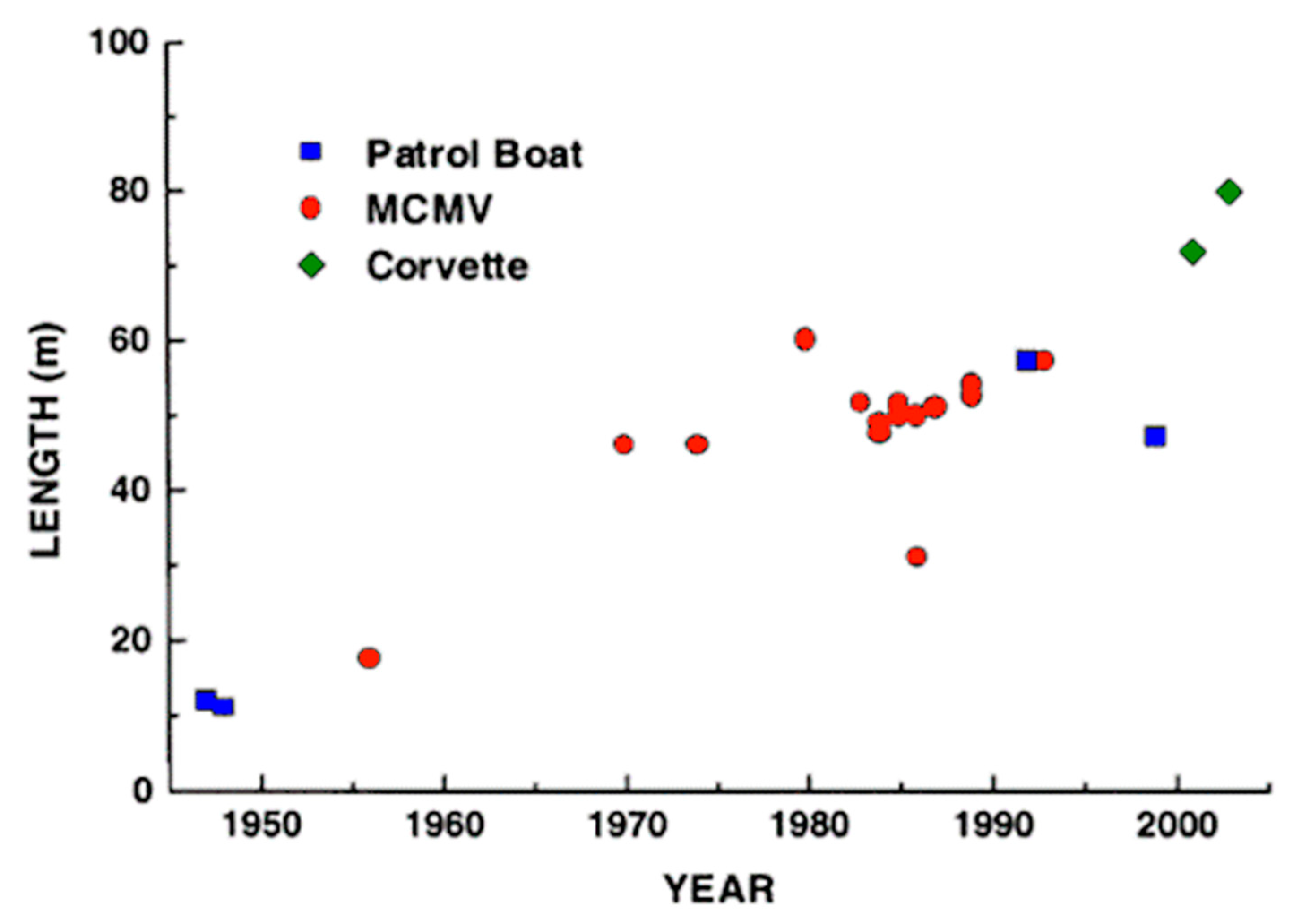
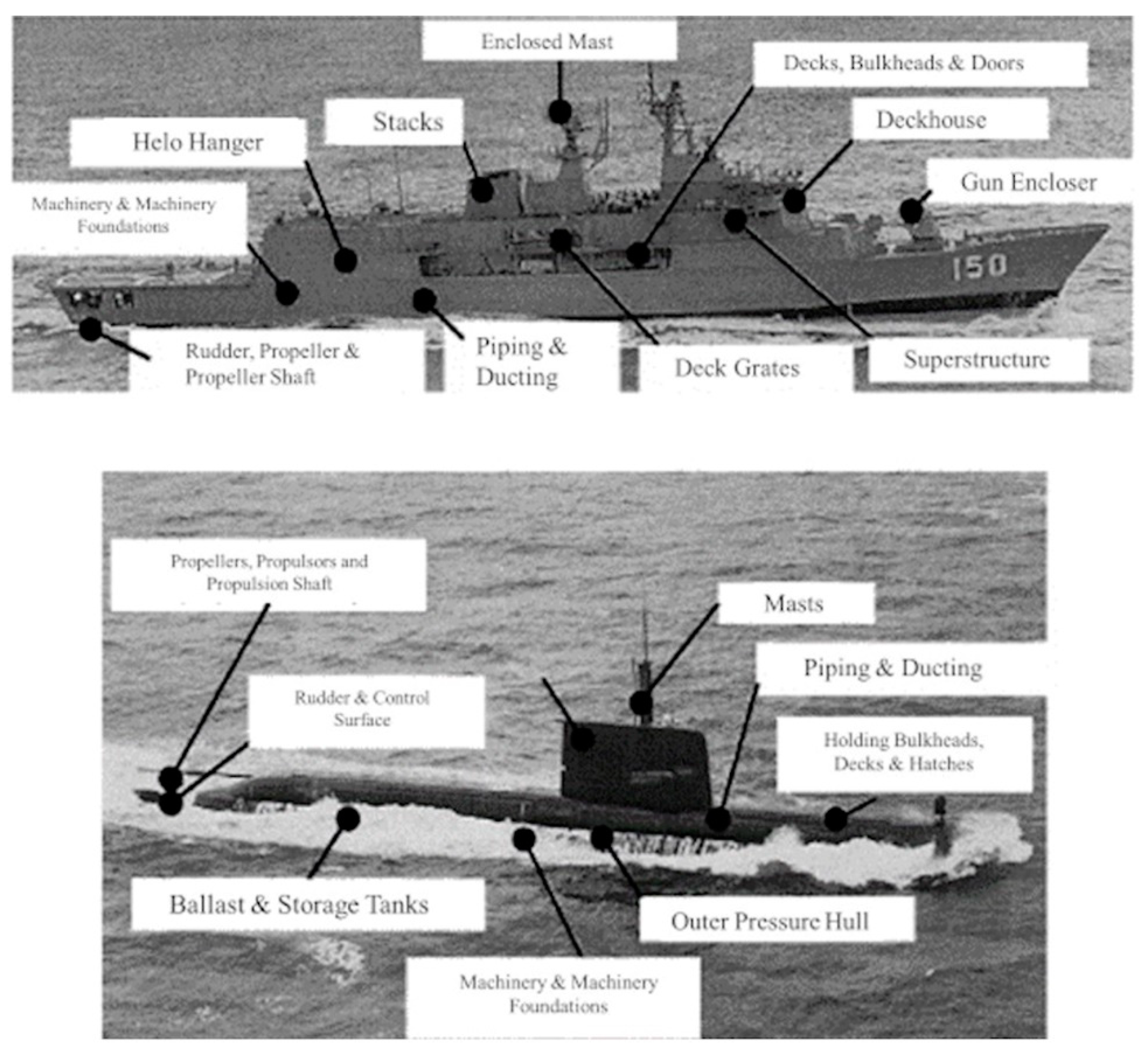
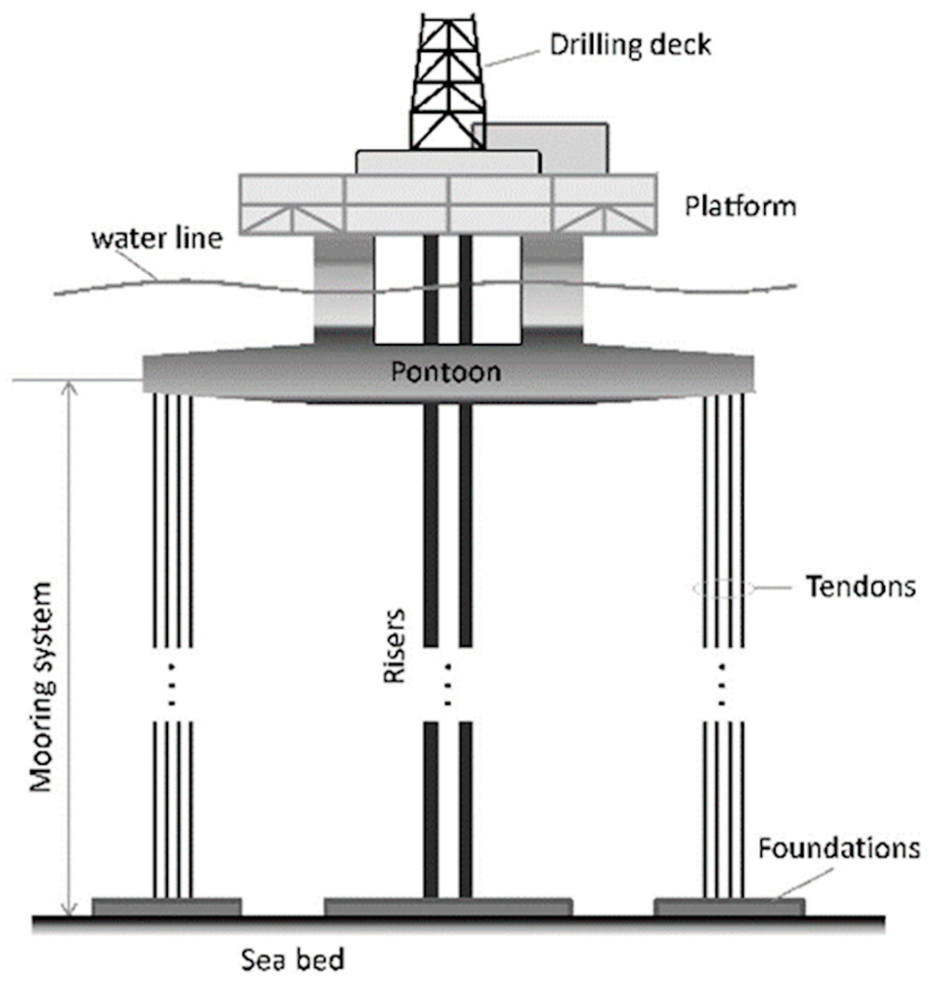
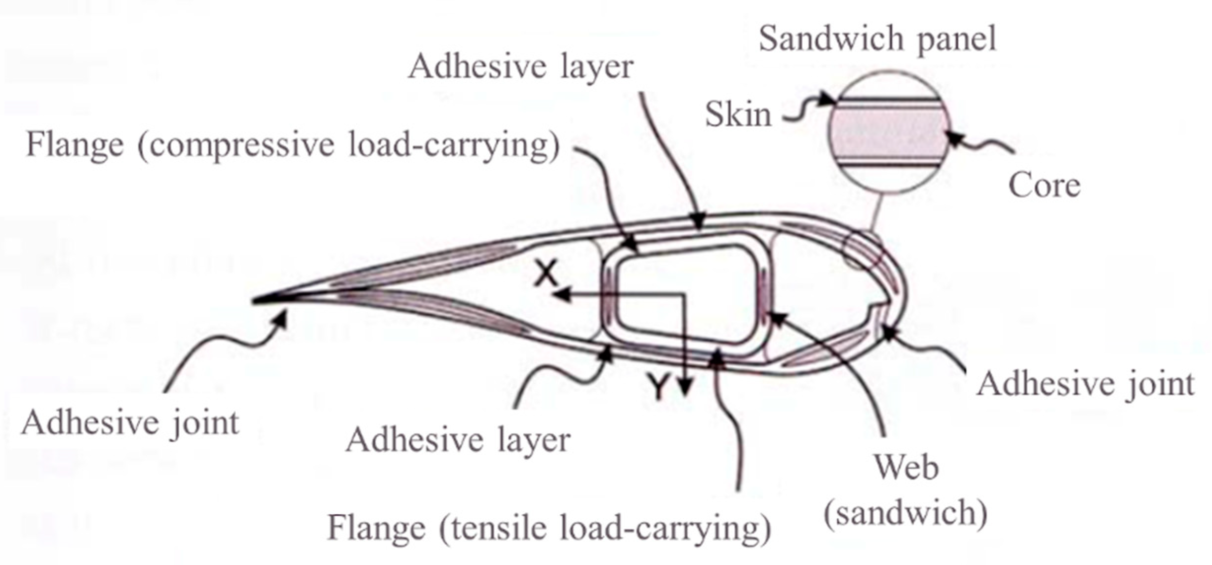
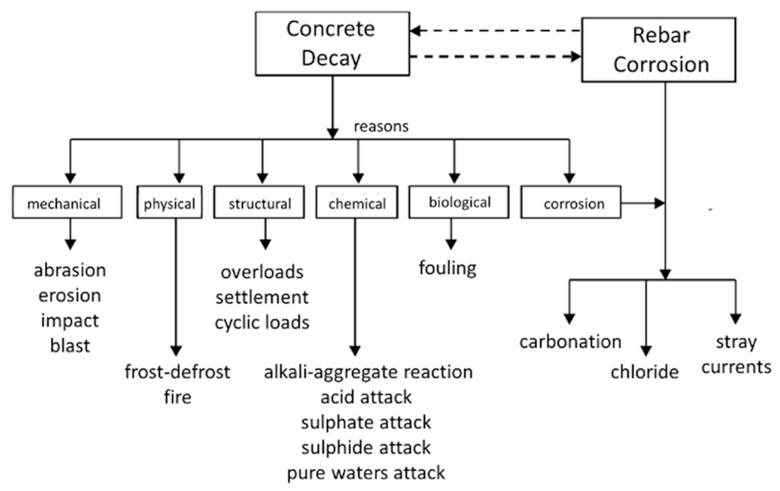
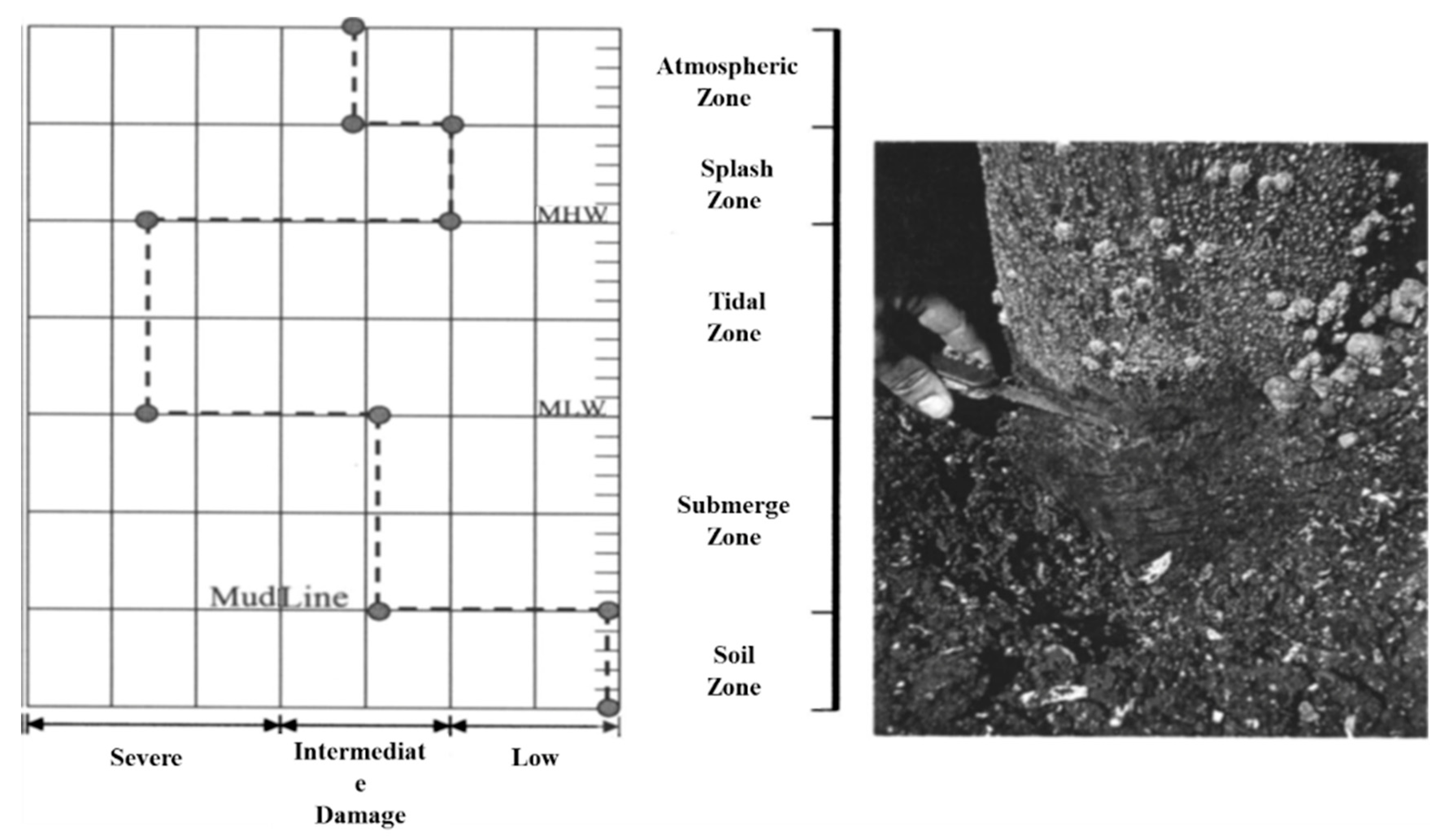
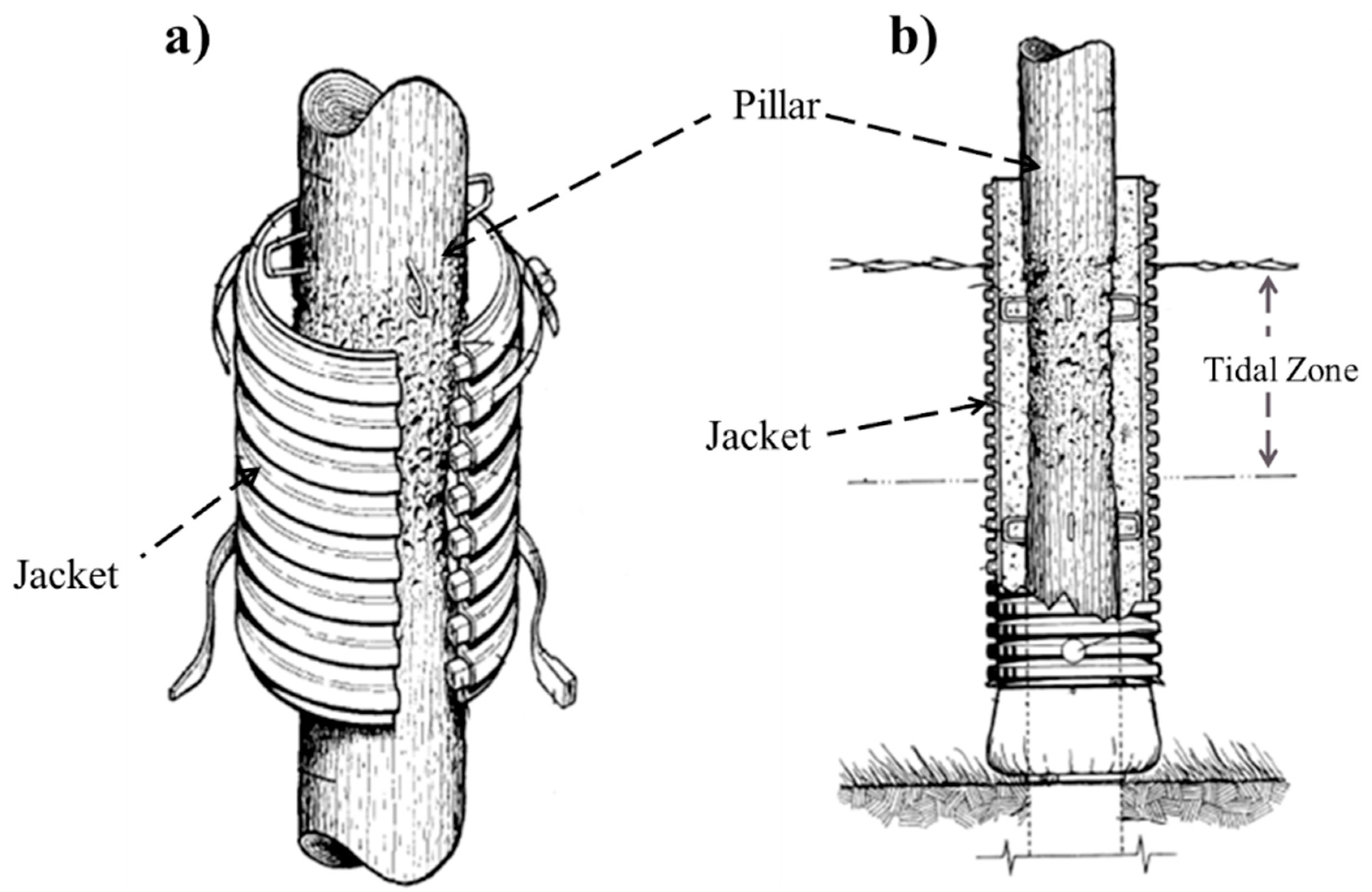