Article

Corrosion Damage Evolution Study of the Offshore Cable-Stayed Bridge Anchorage System Based on Accelerated Corrosion Test

1
State Key Laboratory of Mountain Bridge and Tunnel Engineering, Chongqing Jiaotong University, Chongqing 400074, China
2
School of Civil Engineering, Chongqing Jiaotong University, Chongqing 400074, China
*
Author to whom correspondence should be addressed.
J. Mar. Sci. Eng. 2023, 11(5), 896; https://doi.org/10.3390/jmse11050896
Submission received: 10 April 2023 / Revised: 19 April 2023 / Accepted: 21 April 2023 / Published: 22 April 2023
(This article belongs to the Special Issue Failure Analysis of Marine Structure II)

Abstract

:
The cable-stayed bridge anchorage system is prone to serious corrosion problems in the offshore environment, threatening its service safety. Based on the copper accelerated salt spray (CASS) test, the anchorage system was subjected to accelerated corrosion and then dissected along the axial direction to study the corrosion damage evolution of the internal structure. This revealed the evolution of corrosion damage in the anchorage system of offshore cable-stayed bridges. The results show that in the offshore environment, a large number of corrosion factors enter the interior of the cable anchorage system through the splicing seam at the junction of the anchor cup and the connecting barrel, and spread to both ends, thus causing corrosion damage to the anchor cup, connecting barrel, filling medium and cable steel wires. Inside the cable of the anchorage system, cross-sections with a higher corrosion level on the outer circle steel wires will also have a higher overall corrosion level. The outer circle steel wires are less able to meet the strength requirements, because they withstand most of the corrosion effects, and the corrosion pits on the surface of the steel wires will render them much weaker than the design tensile strength and fracture. After the CASS test, the ductility of cable steel wires decreases from the inner circle to the outer circle, and the higher the corrosion level of steel wires, the more obvious the brittle indications; the steel wires tend to undergo brittle failure. In the design and manufacture of the cable-stayed bridge anchorage system, special attention should be paid to the corrosion protection of the splicing seam, as well as the corrosion condition and residual strength of steel wires in the outer circle of the cable, to delay the degradation of the mechanical properties and brittle damage of the anchorage system.

1. Introduction

The cable-stayed bridge anchorage system has a complex force structure and variable service environment. The interior of the cable is usually provided with a filling medium [1] and wrapped with a high-density polyethylene (HDPE) sheath [2,3,4], and the steel wires inside the cable need to have high strength and corrosion resistance [5]. The offshore environment has a high content of Cl- and other corrosion factors, high average temperature and humidity, large temperature difference between day and night, and strong air mobility [6], which makes the anchorage system of the offshore cable-stayed bridge more susceptible to corrosion damage. Under the coupling action of electrochemical corrosion [7,8], vehicle loads [9,10], wind loads [11,12], and temperature loads [13], the service safety of the whole bridge is further endangered [14,15,16,17].
A large number of bridge researchers have focused their research on the evolution of the corrosion damage mechanism of cable steel wires of the cable-stayed bridge. Hamilton et al. [18] and Barton et al. [19] conducted accelerated corrosion tests on cables with seawater, studied the uniform corrosion and corrosion cracking of cables under no load and alternating load, and obtained the corrosion fracture characteristics of cables. Wenzhi [20] studied the corrosion mechanism and corrosion damage evolution process of cable steel wires by simulating the service environment of the offshore cable-stayed bridge with the salt spray corrosion test. Xiaoyu et al. [21] carried out an accelerated corrosion test on the cable and analyzed the loss of steel wires’ quality and strength, which helped in predicting the lifetime of cables in actual service [22,23]. Mayrbaurl et al. [24] found that the ductility of corroded steel wires inside the cable in the service environment was lower than that under the test conditions. Marandi et al. [25] concluded that the protective oxide layer produced by immersing galvanized steel wires in salt water medium enhances the resistance of steel wires to corrosion. In general, steel wires with different degrees of corrosion correspond to different degrees of degradation of mechanical properties [26,27,28,29]. Nakamura et al. [30] realized the simulation of the spatial distribution of steel wires with different corrosion degrees by wrapping the steel wires of the main cable of the suspension bridge with wet gauze. Guowen et al. [31] studied the corrosion mechanism of cables based on impressed current cathodic protection and proposed a new concept of active control of cable corrosion protection. Yangguang et al. [32] found that the uniform corrosion process of bridge cables can be divided into two stages: galvanized layer corrosion and iron matrix corrosion, and the significant decrease in mechanical properties such as ductility of corroded steel wires occurs in the iron matrix deterioration stage [33,34,35].
Existing research on the cable-stayed bridge anchorage system mainly focuses on force deformation and new materials and processes. Jingyu [36] analyzed the fatigue damage evolution of the carbon fiber-reinforced polymer cable-stayed bridge anchorage system and investigated the durability of their stress-hygrothermal coupling; for the steel strand cable anchorage system, the fire resistance and slip resistance significantly decrease with the increase of stress [37]. Jingyang et al. [38] and Bo [39] conducted extensive research on the long-term performance of the large-tonnage fiber-reinforced polymer cable anchorage system and developed an extruded anchorage system based on the results. Guowen and Shiya [40] conceived a device of impressed current cathodic protection to implement corrosion protection for the cable anchorage system; on this basis, Guowen and Xuanbo [41] envisioned the construction of a pre-stressed flexible sealing device to achieve more effective vibration-damping and sealing of the anchorage system. Marco et al. [42] proposed a more efficient anchoring scheme for fiber-reinforced composite cables, while the self-anchoring carbon fiber-reinforced polymer cables using composite anchorage systems, group anchorage systems, and optimized anchoring forms can also improve the service stability of anchorage systems [43,44,45].
Currently, a few scholars have studied the corrosion damage of cable-stayed bridge anchorage systems. In this study, the accelerated corrosion test of the offshore cable-stayed bridge anchorage system was carried out according to the copper accelerated salt spray (CASS) test. Through the dissection test, the corrosion condition of each structural system of the anchorage system was evaluated, the corrosion distribution of cable steel wires inside the anchorage system was analyzed, and the corrosion damage evolution process was studied. It provides a reference for the design of the long-term performance of the offshore cable-stayed bridge anchorage system in actual projects, and it performs targeted maintenance and repair of different parts of the offshore cable-stayed bridge anchorage system under service conditions, allowing the remaining service life of the anchorage system of cable-stayed bridges to be evaluated more effectively.

2. Tests

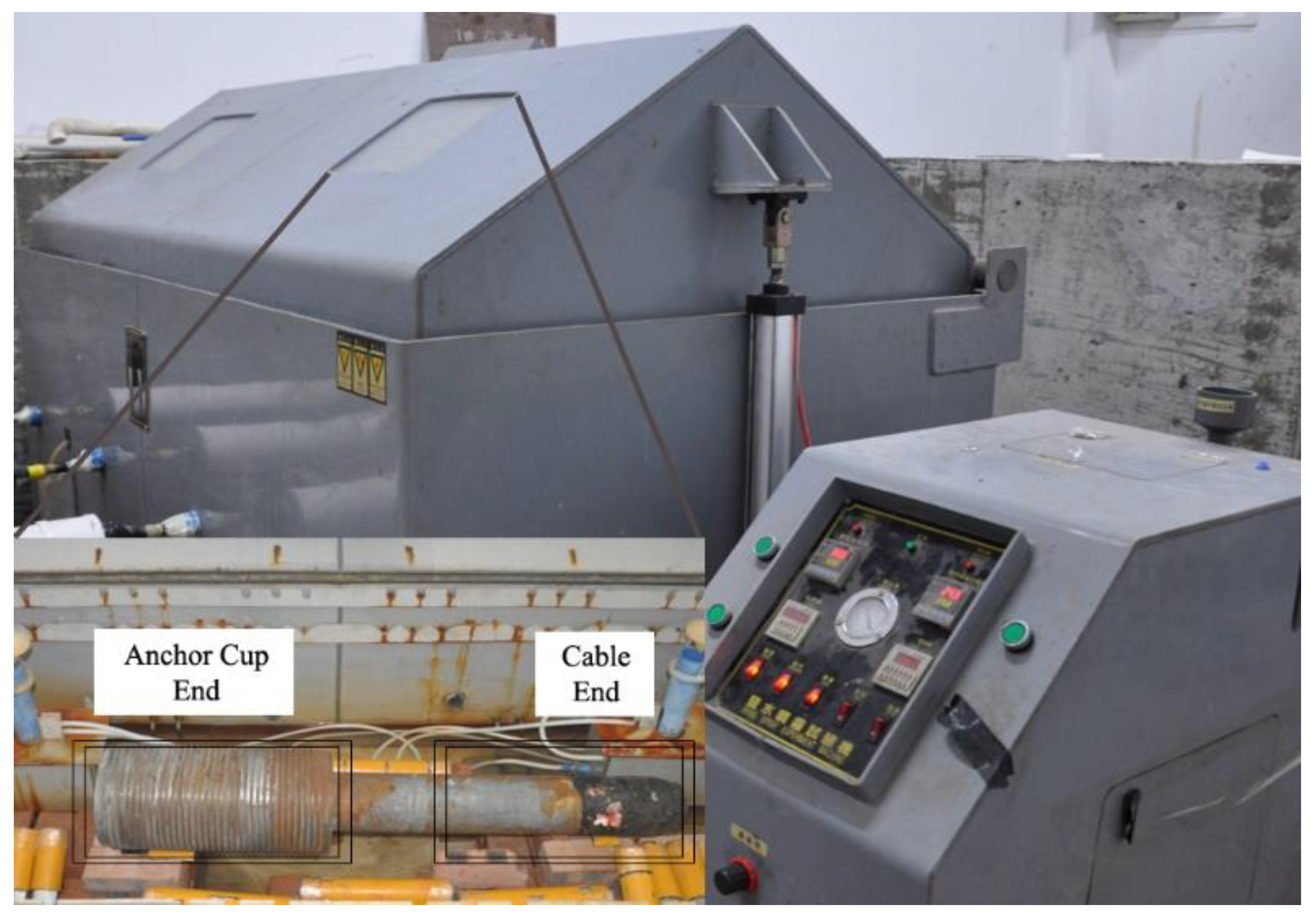
2.1. Accelerated Corrosion Test

The CASS test was used to conduct accelerated corrosion tests on the offshore cable-stayed bridge anchorage system. We increased the ambient temperature of the test, added an appropriate amount of CH3COOH and CuCl2·2H2O into the corrosion solution, and applied the corrosion solution to the anchorage system in a state of salt spray to improve the test efficiency [46,47], so as to simulate the rapid corrosion state of the cable-stayed bridge anchorage system in offshore environment. The anchorage system was kept in an acidic environment of pH = 3.1–3.3 throughout the test, and the humidity was controlled at about 95%. In addition, a large volume salt spray test chamber and a spray device with stable air pressure were selected to provide a guarantee for the uniform settlement of salt spray. The salt spray settlement rate was controlled at 1.5 mL/(80 cm2·h)–2 mL/(80 cm2·h), the temperature in the test chamber was set at 50 °C ± 1 °C, and the test details strictly complied with the relevant specifications [48,49,50].
The configuration of the test corrosion solution was completed using basic reagents such as NaCl, CH3COOH, CuCl2·2H2O, and distilled water, as shown in Table 1 [51].
(1) Dissolved NaCl. By adding appropriate NaCl to distilled water with a temperature range of 23 °C–27 °C and a conductivity of ≤20 mS/m, a NaCl solution with a concentration range of 45 g/L–55 g/L was configured to a pH of about 6.7 at this stage;
(2) Added CuCl2·2H2O. By adding CuCl2 to the solution to accelerate the corrosion rate, the concentration range was controlled at 0.24 g/L–0.28 g/L;
(3) Adjusted pH. The pH of the solution was adjusted to a steady state of 3.1–3.3 by adding an appropriate amount of CH3COOH to the corrosion solution, as described above, and monitored by a precision acidity measuring instrument.
Table 1. Reagents for corrosion solution.
NumberReagents NameSpecificationTechnical ParametersQuantity
1NaCl500 g/bottleAR40
2CuCl2·2H2O500 g/bottleAR2
3CH3COOH500 mL/bottleAR8
Basic tools such as electronic balances, measuring cylinders, beakers, and glass stirring bars were also required in the process of preparing solutions to assist in the weighing, dilution, and dissolution of reagents, as well as the transfer of the corrosion solution, which will not be described here. This test used the salt spray test chamber, air compressor, industrial digital microscope, and digital camera of the State Key Laboratory of Mountain Bridge and Tunnel Engineering of Chongqing Jiaotong University to cooperate with the work, and the specific models and technical parameters of the equipment are shown in Table 2.
After the pretreatment was prepared, polished and cleaned up the surface of the complete anchorage system, and stood for a period of time to make it dry. Cleaned the inside of the salt spray test chamber to avoid interference from other factors to the test and checked the solenoid valve, temperature control system, sensor, and terminal controller inside the salt spray test chamber system to ensure that the air compressor supply is normal and the visual operation interface is operational. Then the two ends of the anchorage system were sealed with epoxy resin and placed on the support inside the test chamber to avoid direct contact with the chamber. As shown in Figure 1, an all-day CASS test was conducted on the anchorage system for 200 days, totaling 4800 h.

2.2. Anchorage System Dissection Test

2.2.1. Basic Parameters
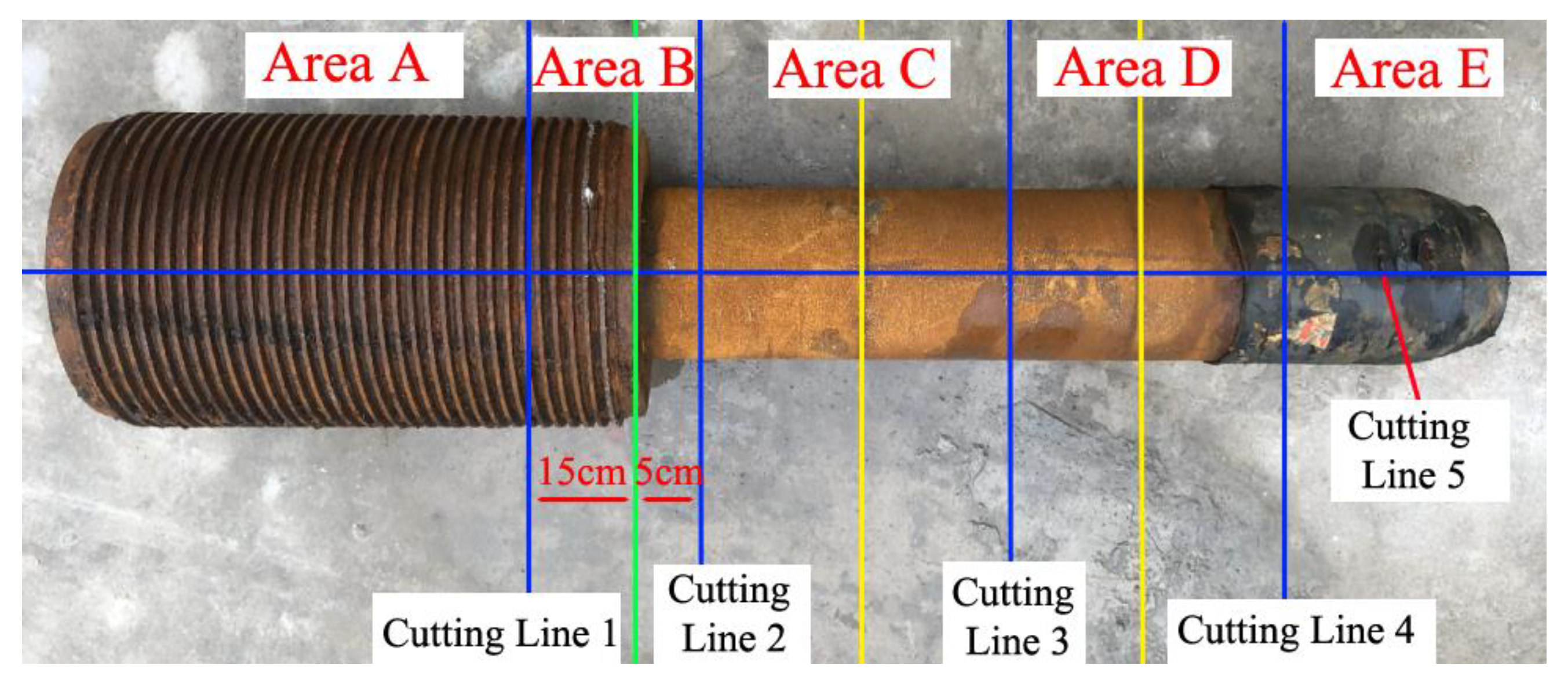
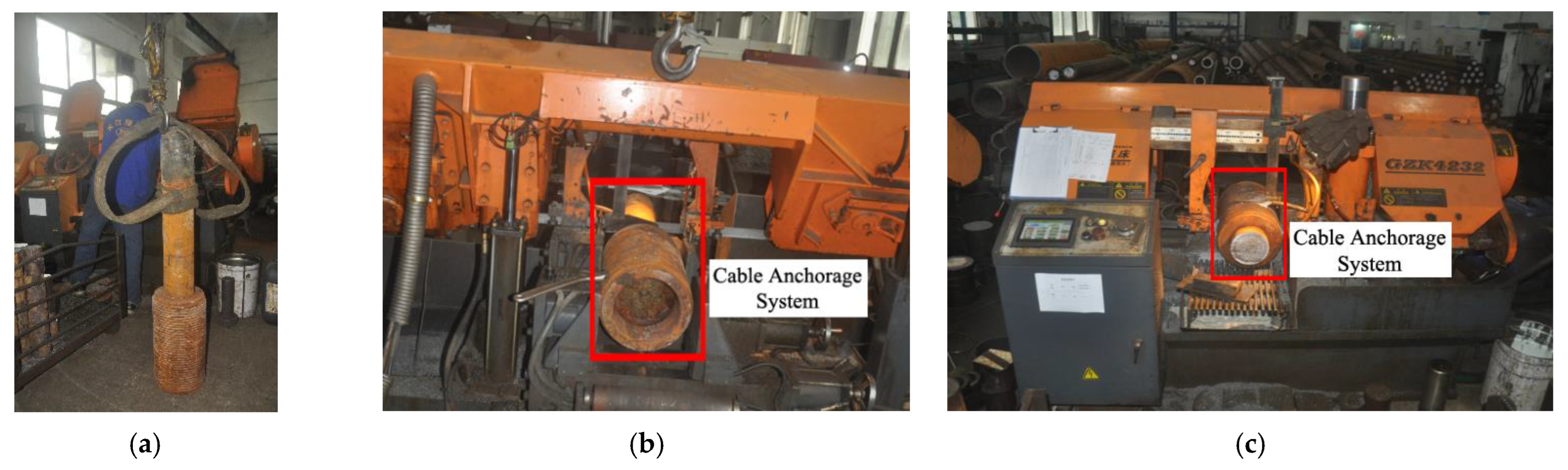
The cable anchorage system used in the CASS test in Figure 1 was disassembled from a cable-stayed bridge cable-changing project in the offshore area of southeast China. The model is LM(1770)-7-121, the anchor cup is made of 42CrMo, the anchor ring is made of 40Cr, and the anchor protective cover is made of 022Cr17Ni12Mo2 stainless steel. The anchorage system’s cable model is LPES(1770)-7-127-Zn; the cable is composed of high-strength galvanized parallel steel wires, with 127 wires arranged in a cross-section, and the steel wires have a diameter of 7 mm and a design tensile strength of 1770 Mpa. The cable protective cover and sealing cover are also made of 022Cr17Ni12Mo2 stainless steel. The cable anchorage system adopts a metal zinc coating for anti-corrosion; the thickness of the zinc coating of the anchor cup and other auxiliary components is ≥90 μm, and the unit mass of the zinc coating on the surface of steel wire is ≥300 g/m2. The basic parameters of the anchorage system are shown in Table 3, and the basic parameters of the cable of the anchorage system are shown in Table 4.

2.2.2. Dissection

The corroded anchorage system was transported to a processing plant in Chongqing, China for dissection, so as to evaluate and analyze the corrosion damage inside the anchorage system. The dissection scheme is shown in Figure 2. The green line segment in Figure 2 is the junction of the anchor cup and the connecting barrel, which is a splicing seam structure. The right side of the green line segment is the connecting barrel, and the structure with screw threads on the left is the anchor cup. The anchor ring is anchored outside the anchor cup and does not form an integral structure with the anchorage system, so it is not part of the test. The dissection process of the anchorage system is shown in Figure 3, and the specific dissection process is as follows:
(1) Carry out the dissection of cutting line 2, which is located to the right of the splicing seam (the green line segment) of the anchor cup and the connecting barrel at a distance of 5 cm;
(2) Carry out the dissection of cutting line 1, which is located to the left of the splicing seam (the green line segment) of the anchor cup and the connecting barrel at a distance of 15 cm;
(3) Longitudinal symmetrical dissection of the left part of cutting line 2 along cutting line 5;
(4) Carry out the dissection of cutting line 3, which is positioned in the center of the connecting cylinder in this section (center of the two yellow line segments);
(5) Longitudinal symmetrical dissection of the portion between cutting line 2 and cutting line 3 along cutting line 5;
(6) The dissection process of cutting line 4 is consistent with steps (4) and (5); the part between cutting line 3 and cutting line 4 is dissected longitudinally and symmetrically along cutting line 5 after the dissection of cutting line 4;
(7) Specify the area of the anchor cup end on the left side of cutting line 1 as area A, the area between cutting lines 1 and 2 as area B, the area between cutting lines 2 and 3 as area C, the area between cutting lines 3 and 4 as area D, and the area of the cable end on the right side of cutting line 4 as area E.
Figure 2. Dissection solution of the anchorage system.
Jmse 11 00896 g002
Figure 3. Dissection of the anchorage system: (a) lifting the anchorage system; (b) dissecting the connecting barrel; (c) dissecting the anchor cup.
Jmse 11 00896 g003
Compared with the anchorage system before the CASS test, the anchorage system after 200 days of accelerated corrosion has a dense red-brown rust layer evenly attached on the surface, and the rust at the screw threads on the outer wall of the anchor cup is darker and the corrosion products accumulate more, indicating that the corrosion of the anchor cup is more serious. After the dissection of the anchorage system is completed, its cross-sections are shown in Figure 4a–d, and the corresponding longitudinal anatomical sections are shown in Figure 4e.
By comparing and analyzing each cross-section, it can be intuitively seen that although the corrosion of the screw threads on the outer wall of the anchor cup is more serious, the internal metal luster and steel wire integrity of the cutting line 1 cross-section (Figure 4a) and cutting line 3 cross-section (Figure 4c) are high, and no obvious corrosion products appear. The corrosion degree of the cutting line 4 cross-section (Figure 4d) near the cable end is at a medium level, the metal luster of both cross-sections and longitudinal sections has significantly decreased; the cross-section shows black or dark gray corrosion patches, and the longitudinal section has yellowish corrosion products attached near the outer circle steel wires. The cutting line 2 cross-section (Figure 4b) has the most serious degree of corrosion; a large amount of red-brown rust appears in the outer circle of the cable, the corrosion depth is deep, and the rust extends from the outer wall of the connecting barrel to the inner cable steel wires.

3. Results and Analysis

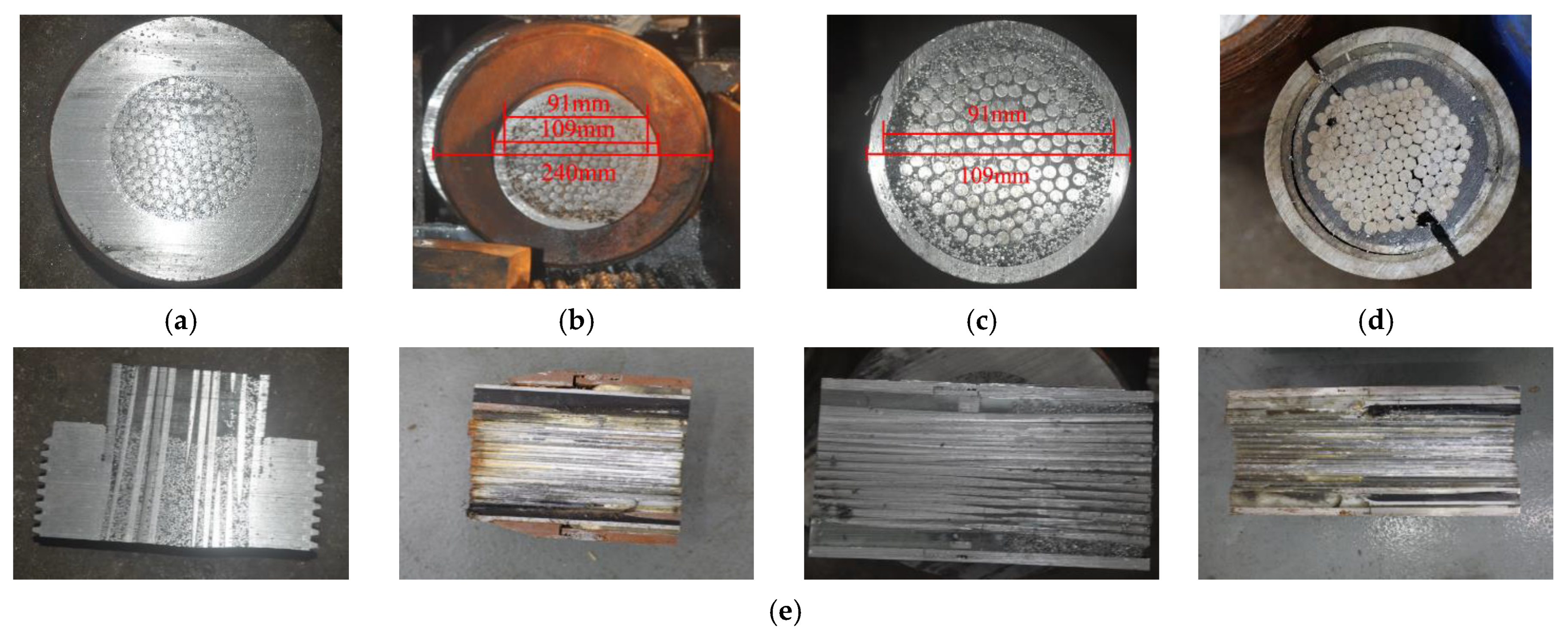
3.1. Anchor Cup, Connecting Barrel and Filling Medium

The offshore cable-stayed bridge anchorage system is filled with epoxy iron sand, which needs to be separated to gain access to the internal steel wires. Firstly, the anchorage system shell was separated from the internal cable to obtain the adhesive body of steel wires and filling medium, and then the epoxy iron sand was chiseled off with a hammer to make the epoxy iron sand come off from the steel wires’ surface. Figure 5 shows the corrosion condition of the anchor cup and filling medium after disassembly.
During the dismantling process, it has been found that there are different degrees of corrosion damage inside the anchorage system. Combined with Figure 2 and Figure 4, the corrosion micromorphology of the anchor cup and connecting barrel in Figure 5a,b is very similar. There are a large number of dark yellow corrosion products generated, the pits of uneven shape and size are all over the surface of the anchor cup and connecting barrel, the pits on the inner wall of the splicing seam of the anchor cup and connecting barrel expand and intersect with the corrosion process, and finally form a long stripe, millimeter-scale corrosion crack as shown in Figure 5a. In general, areas B and C have the most serious corrosion near the splicing seam, followed by the direction of the cable end in area D, and the area between the two yellow line segments of the connecting barrel is less corroded.
The anchor ring depends on the screw threads to anchor the outer wall of the anchor cup, which plays an important role in transmitting the force deformation between the anchorage system and the main beam. The outer wall of the anchor cup gathers more corrosion factors (O2, Cl, sulfide) due to the presence of the screw threads [52], causing damage to and deformation of the screw threads. Although the damage of the screw threads is less damaging to the internal steel wires, it may affect the normal service strength of the anchor ring, which also threatens the service safety of the offshore cable-stayed bridge anchorage system.
As shown in Figure 5c, under the protection of the connecting barrel, there is no large-scale pit in epoxy iron sand, and the main corrosion products are white or gray-black. On the one hand, the white substance is made up of the passivation film ZnO and the corrosion product Zn(OH)2 of the anticorrosive coating of the inner wall of the connecting barrel; on the other hand, it is a loose-textured white Zn5(OH)8Cl2·H2O generated by the further reactions of Cl, CH3COOH, and Cu2+ in the accelerated corrosion test. The gray-black substance is composed of rust spots generated by the reaction of Zn(OH)2, ZnO, and their hydrates with impure gases such as CO2 in the environment; a small amount of black Fe3O4 may also be generated by the epoxy iron sand at a test temperature of 50 °C.
It can be seen from the adhesive body of steel wires and epoxy iron sand shown in Figure 5d that the corrosion degree of epoxy iron sand is more serious than that of steel wires, and epoxy iron sand blocks part of the corrosion factors for the steel wires, providing another guarantee for the corrosion protection of the cable. The corrosion of the HDPE sheath is mainly manifested in the connection parts with other components; as shown in Figure 5e, the connection on the right side of the HDPE sheath has been deformed and generated a lot of rust. The accumulation of corrosion products will squeeze the inside of the HDPE sheath and create gaps with the cable; these gaps provide a favorable space for the aggregation and diffusion of corrosion factors in the offshore environment, accelerating the corrosion rate of the cable. Similar to the HDPE sheath, the epoxy resin shown in Figure 5f is cracked due to large wind and temperature loads during the service of the offshore cable-stayed bridge, causing more corrosion products to accumulate there, the accumulation of corrosion products reacts on the cracks, and the two promote each other. Although epoxy resin does not directly participate in the force and electrochemical reaction of the anchorage system, the rapid development of cracks reduces the bonding performance while providing diffusion channels for corrosion factors, thereby reducing the integrity of the anchorage system.

3.2. Corroded Cable Steel Wires

3.2.1. Morphology and Weight Loss

In order to study the corrosion characteristics of cable steel wires inside the cable-stayed bridge anchorage system, after the epoxy iron sand was chiseled clean, steel wires were classified by the number of laps they belong to, and then the corrosion morphology was observed by an industrial digital microscope. According to the dissection test of the anchorage system, the corrosion degree of area A is insignificant, while the fracture of area E at the cable end is artificially truncated, and is far from the anchorage system, thus its corrosion level is not highly correlated with the anchorage system. Therefore, areas B, C, and D are the main research objects of the following. The outermost steel wires of the cable cross-section are specified as circle 1, and from the outer ring to the inner ring are circles 1 to 6, respectively. The corrosion micromorphology of steel wires shown in Figure 6 corresponds to circles 1 to 6 from top to bottom. Circle 7 is the most central steel wire located in the cable cross-section, which was destroyed during the longitudinal symmetrical dissection along cutting line 5 and is not considered at first.
From Figure 6, it is easy to see that the three areas of the outer circle steel wires have obvious corrosion characteristics, especially the galvanized layer of circle 1 steel wires in areas B and C is basically completely destroyed and part of the white zinc compounds remained. The corrosion medium has invaded the iron matrix, and the composition of the rust on the steel wires’ surface is mainly red-brown Fe2O3, in addition to black Fe3O4, yellow FeOOH, and red-brown Fe(OH)3. The galvanized layer of circle 2 to 4 steel wires shows different degrees of localized corrosion damage, and the iron matrix is exposed.
Compared with the steel wires of circle 1, the steel wires of circle 2 to 4 have shallower breakage depth and smaller breakage extent, and the corrosion becomes lighter from the outer circle to the inner one. The shape and texture of these steel wires are similar to those of the anchor cup, with white ZnO, Zn(OH)2, and Zn5(OH)8Cl2·H2O attached to the surface; the iron matrix surface is also tightly attached with white Fe(OH)2. The steel wires of circle 2 to 4 expose a certain black iron matrix but do not produce red-brown rust, indicating that the iron matrix does not participate in the reaction and the galvanized layer still plays a cathodic protection role as a sacrificial anode for steel wires. The steel wires of circles 5 and 6 show almost no traces of corrosion, with a high gloss on the galvanized layer and only slight scratches on the surface of the steel wires; these scratches are formed by the relative slippage between cable steel wires inside the anchorage system during service.
Three representative steel wires were selected from each circle (6 circles in total) in areas B, C, and D, and a total of 54 steel wires were divided into three groups according to their respective regions. The length of the steel wires after cutting was 16.8 cm in area B, 23.3 cm in area C, and 28.5 cm in area D. The rust layer on the surface of the corroded steel wires was cleaned with a brush in flowing water, and the cleaned steel wires were placed in a desiccator for drying before being weighed and recorded with an electronic balance in turn. According to the recorded data of the difference between the pre-corrosion mass and the mass after corrosion of each steel wire section, the weight loss quantity of corroded steel wires was calculated as shown in Figure 7.
The weight loss quantity of steel wires in Figure 7 quantitatively describes the effect of corrosion on the quality of steel wires in different areas; the weight loss quantity of corroded steel wires is smaller as the distribution of the steel wires approaches the center of the cable cross-section. In group three, the weight loss quantity of circle 1 and 6 single steel wire in areas B and C both exceed 0.44 g, while the corrosion weight loss quantity of circle 1 steel wires in area D is only half that of the remaining two areas. In addition, the corrosion weight loss quantity of individual steel wires near the inner circle is negative, because steel wires near the inner circle have a very low corrosion degree, and steel wires in the anchorage system may be adhered to the filling medium or corrosion products of the outer steel wires, resulting in an increase in the quality of these steel wires instead of a decrease.
The corrosion weight loss rate was expressed by dividing the weight loss quantity by the pre-corrosion mass of each steel wire section, and is used to make dimensionless the corrosion weight loss quantity of steel wires with different lengths to compare the corrosion degree of steel wires in different areas. The initial mass of steel wires is converted according to the mass per unit length of 301 g/m [4] for the 7 mm cable steel wire in the relevant specifications. As can be seen from the corrosion weight loss rate in Figure 7, the corrosion weight loss rate of the outer circle steel wires is much higher than that of the inner circle, especially the corrosion weight loss rate of circles 1 and 2 steel wires in the outermost circle, which shows a cliff-like decline, while the corrosion weight loss rate from circle 2 to circle 6 steel wires shows a slow decline, and from circle 4, the corrosion weight loss rate of steel wires in each area is basically within 0.2%. The corrosion weight loss rate of circle 1 steel wires in areas B and C is much higher than 0.6%, and the corrosion weight loss rate of circle 1 steel wires in area B is the most serious in group 3, reaching 0.87%, which is the highest among all steel wires. While the corrosion weight loss rate of steel wires in area D is always maintained at a low level, the corrosion weight loss rate of steel wires in circles 1 and 6 in area D is not much different, and the corrosion protection effect in area D is relatively good in the whole anchorage system.

3.2.2. Space Distribution

From the viewpoint of material and fabrication process, steel wires inside the anchorage system of cable-stayed bridges are the same as steel wires inside the cable. The only difference is that the steel wires inside the cable are wrapped by HDPE sheaths, while the steel wires inside the anchorage system, besides the HDPE sheath at the cable end, are also wrapped by anchor cups and connection barrels near the anchor cup and filled with epoxy iron sand. The corrosion level of the corroded steel wires inside the anchorage system was graded by the corrosion classification of cable wire from Jun [53]. The spatial distribution cloud diagrams of the corrosion level of cable steel wires inside the anchorage system are shown in Figure 8.
It can be seen from Figure 8 that the corrosion distribution of steel wires has a certain symmetry, and the average corrosion grade of every cross-sectional steel wire shows a decreasing trend from the outer circle to the inner. It is worth noting that the corrosion level of circle 1 steel wires in the right-most cross-section in area B and the left-most cross-section in area C all reached level V and VI. The cross-section with a higher corrosion degree of the outer circle steel wires will also have a higher overall corrosion level, but the inner circle of the cross-section still has almost no corrosion damage steel wires, because the outer circle steel wires block most of the corrosion factors for the inner circle steel wires and withstand most of the corrosion effects.
The corrosion level is particularly serious at the splicing seam of the right side of area B and the left side of area C; the corrosion level of circle 3 steel wires near this area has reached level IV, while on the left side of areas B and D and the right side of area C, the corrosion level of steel wires is not high and most are below level III.
To more intuitively describe the axial distribution of the cable steel wires’ corrosion inside the anchorage system, the axial distribution of the steel wires with corrosion level IV, V and VI is mainly investigated, as shown in Figure 9. The meanings of each color line segment in Figure 9 are the same as in Figure 2. The highest number of steel wires at level VI with the most severe corrosion occurs in the area between the splicing seam and cutting line 2, and the highest number of steel wires at level IV and V are distributed in the area near cutting line 2. However, there is almost no high-level corrosion damage on steel wires in the cross-section near cutting line 3, which is consistent with the rules in the previous dissection test and also consistent with the conclusion that the corrosion of the cable near the circumferential crack is serious in the existing research [54,55]. The splicing seam of the anchor cup and the connecting barrel can also be regarded as a very small width annular opening, which becomes a favorable channel for the entry and diffusion of corrosion factors. After the corrosion factors in the offshore environment enter the anchorage system, they diffuse to the anchor cup end and the cable end along the internal void, filling medium, and the inner wall of the anchor cup and connecting barrel, respectively, causing corrosion of steel wires in the corresponding position. In the design and manufacture of cable-stayed bridge anchorage systems, special attention should be paid to the seals and corrosion protection measures of the splicing seam. Additionally, the integrated structure of the anchor cup and connecting barrel should be taken into consideration, and the gap generated by the splicing seam should be minimized to reduce the possibility of corrosion factor invasion.
The highest number of steel wires with corrosion levels of IV, V and VI appears on the right side of the splicing seam, and the number of steel wires with a corrosion level of VI maintains a high level within about 20 cm to the right side of the splicing seam, which indicates that the diffusion of corrosion factors to the cable end is obviously easier, and the inner structure of the connecting barrel is more conducive to the diffusion of corrosion factors. In the area near cutting line 4, the number of steel wires with corrosion levels of IV and V increases to a certain extent, which can be explained by the poor sealing performance of area D at the break at the cable end on the right side of cutting line 4 in the CASS test.

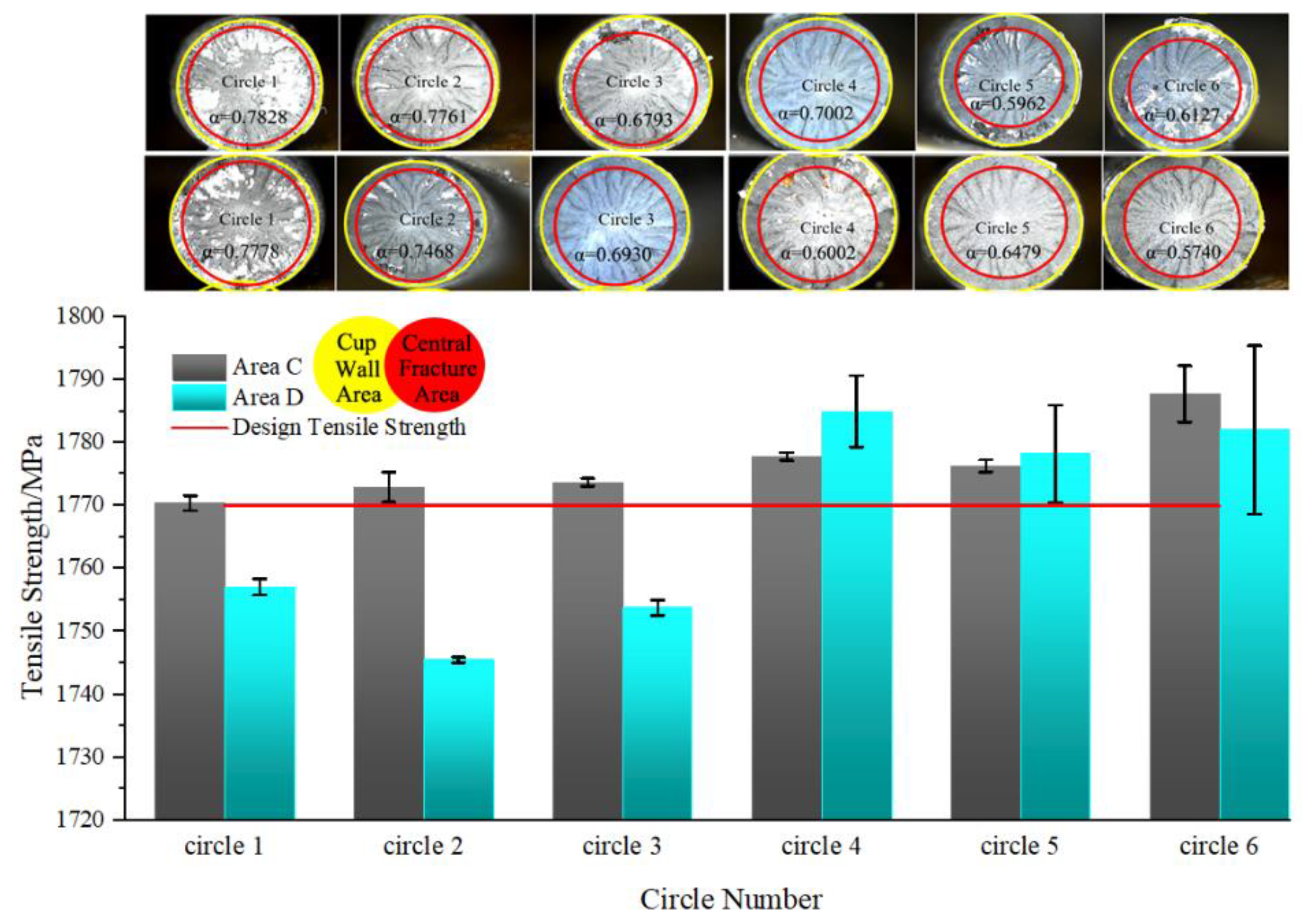
3.2.3. Mechanical Properties

The mechanical tensile test was carried out using the corroded steel wires that were preserved well in the previous test and met the requirements of the specification. It was used to analyze the mechanical properties of steel wires inside the cable of the cable-stayed bridge anchorage system. The microcomputer-controlled dual-arm electronic universal testing machine (model: WDW-50) of the State Key Laboratory of Mountain Bridge and Tunnel Engineering of Chongqing Jiaotong University was used in the test, and the loading rate was set at 1.9 kN/s [4,56]. It should be noted that the length of the steel wires in area B is much shorter than that in areas C and D in the dissect test, so it is difficult to meet the tensile requirements. According to the comprehensive consideration of relevant specifications [57], variable control, and equipment restrictions, only area C and area D steel wires of similar lengths were tested in the tensile test, by changing the length of fixed ends at both ends of steel wires to meet the requirements of the actual tensile length. The morphology and strength data of the tensile fracture are shown in Figure 10.
The tensile test of steel wires in various regions shows that the closer the steel wires are to the inner circle, the lower the strength loss rate, and the closer the steel wires are to the outer circle, the lower the probability of meeting the design tensile strength requirements, and individual steel wires’ residual strength in the outer circle only retain half the level of the design tensile strength. The fabrication of cable steel wires inside the anchorage system basically meets the strength safety factor in bridge engineering; after experiencing a small degree of corrosion damage, the tensile strength of the inner circle steel wires still meets the design tensile strength of 1770 MPa and even exceeds 1790 MPa.
By observing the fracture morphology of steel wires in different areas, it can be seen that the steel wires have relatively obvious necking phenomena, and the fractures are cup-shaped, showing different degrees of ductile fracture. The tensile data shows that there is no obvious yield step in the whole test, and the ductility of steel wires decreased to different degrees. Further, we define α as an important indicator to measure the ductility of steel wires, which is the ratio of central fracture area to cup wall area. The central fracture area is the brittleness indication of steel wires, which consists of the dimple in the central fiber region and the radial fringe shear lip around the typical transient fracture area. The cup wall area is the plastic indication of steel wires and refers to the cup-shaped neck region formed by plastic deformation along the outer edge of the cross-section. When steel wires are distributed from the outer circle to the inner, although the cup wall area does not change much, the central fracture area increases significantly. Therefore, the α value gradually increases from the inner circle to the outer, and the values of the α of circle 6 steel wires in areas C and D are 0.6127 and 0.5740, respectively, while the values of the α of circle 1 steel wires reach 0.7828 and 0.7778, with a growth rate of more than 30% compared to circle 6 steel wires. The reason for this situation is that the surface of the outer circle steel wires with more serious corrosion forms more corrosion pits, and these corrosion pits will have serious stress concentration in the case of axial stretching. Excessive stress makes the fracture process of the steel wires from the elastoplastic deformation stage immediately enter the brittle fracture stage, and the development process is rapid, which also explains the reason why the corroded steel wires break when the tensile strength is lower than the design tensile strength. In general, the ductility of steel wires decreases from the inner circle to the outer, the brittle indication of steel wires with a higher corrosion degree is more obvious, and the steel wires tend to undergo brittle failure, which directly causes the service life of cable steel wires inside the cable-stayed bridge anchorage system in the offshore environment to be more difficult to predict. Corrosion protection measures of sealing, applied current and sacrificial anode should be taken for the internal ropes of cable-stayed bridge anchorage system to slow down the degradation of the mechanical properties of the ropes, and mechanical tests of the residual strength of the internal ropes of the anchorage system should be conducted periodically to prevent the brittle damage of the anchorage system without forewarning.
Since both ends of the steel wires need to be used as the fixed section of the universal testing machine in the tensile test of corroded steel wires, the fracture position of the steel wires is mainly in the middle of area C and area D (corresponding to the two yellow line segments of the connecting barrel in Figure 2). However, since the main corrosion damage in areas C and D occurred in the direction of the splicing seam and the cable end, respectively, the difference in corrosion degree of the steel wires’ fracture position is not obvious, which makes the average fracture strength of the steel wires in the two areas basically at the same degree, although there are differences in the degree of local corrosion. In addition, the randomness of the tensile strength of the inner circle steel wires is obviously stronger, and its error range is larger, presumably because the inner circle steel wires with less corrosion damage have greater ductility, and the plastic deformation of the steel wires at a higher level of tensile strength may make the measured strength data have more uncertainty.

4. Conclusions

Based on the CASS test, accelerated corrosion of the offshore cable-stayed bridge anchorage system was carried out. The anchorage system was dissected along the axial direction, the corrosion behavior characteristics were analyzed according to the corrosion morphological characteristics of the anchorage system’s internal structure, the spatial distribution of corrosion damage and mechanical properties of the cable steel wires were studied, and the corrosion damage evolution process of the offshore cable-stayed bridge anchorage system was revealed. The following conclusions are drawn:
(1) A large number of corrosion factors in the offshore environment will enter the interior of the cable anchorage system through the splicing seam at the junction of the anchor cup and the connecting barrel, resulting in the most serious corrosion in the splicing seam area. The corrosion factors mainly spread from the splicing seam to both ends of the anchorage system, causing corrosion damage to the anchor cup, connecting barrel, and filling medium, eventually corroding the cable, which is the main load-bearing structure. The corrosion level of the steel wires in the direction of the cable end of the splicing seam is higher, and the internal structure of the connecting barrel is more conducive to the diffusion of corrosion factors.
(2) Inside the cable of the anchorage system, the outer circle steel wires bear most of the corrosion effect; the higher the corrosion degree of the outer circle steel wires, the higher the overall corrosion level will be. The fracture of the outer circle steel wires will lead to stress redistribution in the cable, and the steel wires with the most severe corrosion often determine the service life of the anchorage system. During the inspection of the bridge anchorage system, extra attention should be paid to the corrosion of the outer circle steel wires of the cable.
(3) Inside the cable of the anchorage system, the probability of the steel wires distributed in the outer circle meeting the design tensile strength requirements is much lower. The steel wires of the outer circle will form more corrosion pits on the surface; these corrosion pits will have serious stress concentration in the case of axial stretching, and the excessive stress will make the fracture process of the steel wires from the elastoplastic deformation stage immediately enter the brittle fracture stage, the tensile strength of the corroded steel wires is lower than the design tensile strength and fracture occurs. The ductility of cable steel wires decreases from the inner circle to the outer circle; the higher the corrosion level of the steel wires, the more obvious the brittle indications, and the steel wires tend to undergo brittle damage.

Author Contributions

Conceptualization, G.Y., X.H. and Q.W.; methodology, X.H.; software, G.Y., H.L. and J.L.; validation, G.Y., J.L. and Q.W.; formal analysis, G.Y., X.H., H.L. and Q.W.; investigation, X.H. and H.L.; resources, H.L., J.L. and Q.W.; data curation, G.Y. and J.L; writing—original draft preparation, G.Y., X.H., H.L. and Q.W.; writing—review and editing, G.Y. and X.H.; visualization, X.H. and H.L.; supervision, G.Y. and X.H. All authors have read and agreed to the published version of the manuscript.

Funding

The National Natural Science Foundation of China (Grant No. 52178273), the Natural Science Foundation of Chongqing (Grant No. cstc2021jcyj-msxmX1159), the Chongqing Talent Plan Project (Grant No. cstc2022ycjh-bgzxm0124), the Open Fund Project of State Key Laboratory of Mountain Bridge and Tunnel Engineering (Grant No. SKLBT-YF2105), the Chongqing Project of Joint Training Base Construction for Postgraduates (Grant No. JDLHPYJD2020004), the Innovation Program for Graduate Student of Chongqing (Grant No. CYS22392).

Institutional Review Board Statement

Not applicable.

Informed Consent Statement

Not applicable.

Data Availability Statement

The data presented in this study are available on request from the corresponding author.

Conflicts of Interest

The authors declare no conflict of interest.

References

  1. Zheng, J.; Ruan, X.; Du, H. Design of the oblique saddle-type pylon anchorage system for cable-stayed bridges. Struct. Eng. 2014, 30, 19–24. [Google Scholar]
  2. Xu, J.; Chen, W. Behavior of wires in parallel wire stayed cable under general corrosion effects. J. Constr. Steel Res. 2013, 85, 40–47. [Google Scholar] [CrossRef]
  3. McTavish, S.; Raeesi, A.; D’Auteuil, A.; Yamauchi, K.; Sato, H. An investigation of the mechanisms causing large-amplitude wind-induced vibrations in stay cables using unsteady surface pressure measurements. J. Wind Eng. Ind. Aerodyn. 2018, 183, 19–34. [Google Scholar] [CrossRef]
  4. JT/T775-2016; Cable of Parallel Wires for Large-Span Cable-Stayed Bridge. China Communications Press: Beijing, China, 2016.
  5. Borchers, C.; Kirchheim, R. Cold-drawn pearlitic steel wires. Prog. Mater. Sci. 2016, 82, 405–444. [Google Scholar] [CrossRef]
  6. Gao, Z.; Ruan, H.; Qin, S.; Ma, R.; Mei, D. Technical status, challenges and solutions of marine bridge engineering. Strateg. Study CAE 2019, 21, 1–4. [Google Scholar] [CrossRef]
  7. Reza Kashyzadeh, K.; Amiri, N.; Maleki, E.; Unal, O. A Critical Review on Improving the Fatigue Life and Corrosion Properties of Magnesium Alloys via the Technique of Adding Different Elements. J. Mar. Sci. Eng. 2023, 11, 527. [Google Scholar] [CrossRef]
  8. Wang, D.; Song, D.; Xu, W.; Zhang, D. Effect of fretting frequency on tension-torsion fretting corrosion fatigue behavior of steel wire. Tribology 2021, 41, 964–973. [Google Scholar]
  9. He, X.; Guo, Z.; Xu, H. Vehicle impact effect of suspender in half-through arch bridge considering vehicle-bridge coupled vibration. Noise Vib. Control 2022, 42, 206–213. [Google Scholar]
  10. Editorial Department of China Journal of Highway and Transport. Review on China’s bridge engineering research: 2021. China J. Highw. Transp. 2021, 34, 1–97. [Google Scholar]
  11. Liao, H.; Li, M.; Ma, C.; Wang, Q.; Sun, Y.; Zhou, Q. State-of-the-art review of bridge wind engineering in 2019. J. Civ. Environ. Eng. 2020, 42, 56–66. [Google Scholar]
  12. Liu, Q.; Zheng, Y.; Bai, Y.; Shao, Q.; Liu, X.; Ma, W. Parametric optimization of aerodynamic anti-vibration measure for rain-wind induced vibration of cables. J. Vib. Shock 2015, 34, 31–35. [Google Scholar] [CrossRef] [PubMed]
  13. Hu, J.; Zheng, Q.; Zhang, W. Study of combined effects of wind and thermal loads on Changtai Changjiang River Bridge. Bridge Constr. 2020, 50, 42–47. [Google Scholar]
  14. Hu, Z. Experimental Study on the Fatigue Properties and Time-Dependent Corrosion Model of Coastal Bridge Suspenders. MA.Eng. Thesis, Chongqing Jiaotong University, Chongqing, China, 2020. [Google Scholar]
  15. Chen, Y.; Xu, H.; Yu, Y. Accident analysis of lowered/half supported tied arch bridges and enlightments for bridge detection. J. Fujian Univ. Technol. 2013, 11, 213–217. [Google Scholar]
  16. Ye, J.; Zhong, J. Corrosion and protection of bridge cable systems. Steel Constr. 2005, 2, 85–89. [Google Scholar]
  17. Zhu, Z. Experimental Study on the Damage Mechanism of Parallel Wire Cable Under Coupling Load and Electrochemical Corrosion. MA.Eng. Thesis, Chongqing Jiaotong University, Chongqing, China, 2018. [Google Scholar]
  18. Hamilton, I.H.R.; Breen, J.E.; Frank, K.H. Bridge stay cable corrosion protection. II: Accelerated corrosion tests. J. Bridge Eng. 1998, 3, 72–81. [Google Scholar] [CrossRef]
  19. Barton, S.C.; Vermaas, G.W.; Duby, P.F.; West, A.C.; Betti, R. Accelerated corrosion and embrittlement of high-strength bridge wire. J. Mater. Civ. Eng. 2000, 12, 33–38. [Google Scholar] [CrossRef]
  20. Li, W. Experimental Research on Stress Corrosion and Corrosion Fatigue Under Salt Fog Environment and Loading. MA.Eng. Thesis, Chongqing Jiaotong University, Chongqing, China, 2015. [Google Scholar]
  21. Chen, X.; Tang, M. Corrosion rate of non-galvanized high-strength steel wires under different temperature and humidity conditions. J. Southwest Jiaotong Univ. 2018, 53, 253–259. [Google Scholar]
  22. Wu, G. Experimental Study on Stress Corrosion and Corrosion Fatigue of Stay Cables Under Acid Rain Condition. MA.Eng. Thesis, Chongqing Jiaotong University, Chongqing, China, 2015. [Google Scholar]
  23. Nakamura, S.I.; Suzumura, K.; Tarui, T. Mechanical properties and remaining strength of corroded bridge wires. Struct. Eng. Int. 2004, 14, 50–54. [Google Scholar] [CrossRef]
  24. Mayrbaurl, R.M.; Camo, S. Cracking and fracture of suspension bridge wire. J. Bridge Eng. 2001, 6, 645–650. [Google Scholar] [CrossRef]
  25. Marandi, L.; Sen, I. Effect of saline atmosphere on the mechanical properties of commercial steel wire. Metall. Mater. Trans. 2019, 50, 132–141. [Google Scholar] [CrossRef]
  26. Nakamura, S.I.; Suzumura, K. Hydrogen embrittlement and corrosion fatigue of corroded bridge wires. J. Constr. Steel Res. 2008, 65, 269–277. [Google Scholar] [CrossRef]
  27. Wang, Y.; Ye, H.; Duan, X. Hydrogen embrittlement and corrosion fatigue tests of corroded bridge cables. J. China Foreign Highw. 2014, 34, 110–116. [Google Scholar]
  28. Mang, Y.; Ye, J.; Zou, L.; Chen, Y. Analysis of corrosion and mechanical properties of steel wire of suspension bridge main cable. J. China Foreign Highw. 2008, 4, 144–149. [Google Scholar]
  29. Li, X.; Xie, X.; Pan, X.; Sun, W.; Zhu, H. Experimental study on fatigue performance of corroded high tensile steel wires of arch bridge hangers. China Civ. Eng. J. 2015, 48, 68–76. [Google Scholar]
  30. Nakamura, S.I.; Furuya, K.; Kitagawa, M.; Suzumura, K. Corrosion Performance of New Suspension Bridge Cable Protection; International Association for Bridge and Structural Engineering: Lucerne, Switzerland, 2000. [Google Scholar]
  31. Yao, G.; He, X.; Liu, J.; Guo, Z.; Chen, P. Test study of the bridge cable corrosion protection mechanism based on impressed current cathodic protection. Lubricants 2023, 11, 30. [Google Scholar] [CrossRef]
  32. Yuan, Y.; Liu, X.; Pu, G.; Wang, T.; Zheng, D. Temporal and spatial variability of corrosion of high-strength steel wires within a bridge stay cable. Constr. Build. Mater. 2021, 308, 15. [Google Scholar] [CrossRef]
  33. Betti, R.; West, A.C.; Vermaas, G.; Cao, Y. Corrosion and embrittlement in high-strength wires of suspension bridge cables. J. Bridge Eng. 2005, 10, 151–162. [Google Scholar] [CrossRef]
  34. Suzumura, K.; Nakamura, S.I. Environmental factors affecting corrosion of galvanized steel wires. J. Mater. Civ. Eng. 2004, 16, 1–7. [Google Scholar] [CrossRef]
  35. Yao, G.; Du, G.; Li, S. Corrosion Damage Research of Stayed Cable Under Coupling Salt Spray Environment and Loading; CRC Press: Boca Raton, FL, USA, 2016. [Google Scholar]
  36. Wu, J. A Novel Anchorage System of CFRP Cables and Its Performance. Ph.D. Thesis, Harbin Institute of Technology, Harbin, China, 2018. [Google Scholar]
  37. Cui, Q.; Zhu, M.; Zhang, H.; He, X. Experimental study on fire resistance performance of anchorage system for steel strand. Prog. Steel Build. Struct. 2019, 21, 107–113. [Google Scholar]
  38. Zhou, J.; Wang, X.; Peng, Z.; Wu, Z.; Zhu, Z. Evaluation of a large-tonnage FRP cable anchor system: Anchorage design and full-scale experiment. Eng. Struct. 2022, 251, 113551. [Google Scholar] [CrossRef]
  39. Feng, B. Study on Anchorage System and Its Long-Term Performance for Large Capacity FRP Cable. Ph.D. Thesis, Southeast University, Nanjing, China, 2019. [Google Scholar]
  40. Yao, G.; Li, S.; Chen, P.; Gu, L. A Kind of Bridge Cable Impressed Current Cathodic Protection Method, System and Device. Chinese Patent CN111593354B, 10 May 2022. [Google Scholar]
  41. Yao, G.; He, X.; Wu, Y.; Liu, J.; Li, S.; Jiang, E. Prestressed Flexible Sealing Device for Cable Anchorage System. Chinese Patent CN115418961A, 2 December 2022. [Google Scholar]
  42. Damiani, M.; Quadrino, A.; Nisticò, N. FRP cables to prestress RC beams: State of the art vs. a split wedge anchorage system. Buildings 2021, 11, 209. [Google Scholar] [CrossRef]
  43. Ai, P.; Feng, P.; Lin, H.; Zhu, P.; Ding, G. Novel self-anchored CFRP cable system: Concept and anchorage behavior. Compos. Struct. 2021, 263, 113736. [Google Scholar] [CrossRef]
  44. Li, C.; Guo, R.; Xian, G.; Li, H. Innovative compound-type anchorage system for a large-diameter pultruded carbon/glass hybrid rod for bridge cable. Mater. Struct. 2020, 53, 111966. [Google Scholar] [CrossRef]
  45. Zuo, X.; Li, Q.; Wen, P. Discussion on the design of cable tower grouping-anchorage system of cable-stayed bridge. J. Highw. Transp. Res. Dev. 2021, 15, 30–39. [Google Scholar] [CrossRef]
  46. Suzumura, K.; Nakamura, S.I.; Sakamoto, Y. A study on corrosion prevention paste of suspension bridge cable. Kou Kouzou Rombunshuu 2003, 10, 23–30. [Google Scholar]
  47. Suzumura, K.; Eguchi, T.; Sakamoto, Y.; Nakamura, S.I. Corrosion prevention of suspension bridge cables by S-shaped wire wrapping system. Kou Kouzou Rombunshuu 2003, 10, 31–38. [Google Scholar]
  48. GB/T 10125-2021; Corrosion Tests in Artificial Atmospheres-Salt Spray Tests. Standards Press of China: Beijing, China, 2021.
  49. GB/T 24195-2009; Corrosion of Metals and Alloys-Accelerated Cyclic Tests with Exposure to Acidified Salt Spray, “Dry” and “Wet” Conditions. Standards Press of China: Beijing, China, 2009.
  50. GB/T 20853-2007; Corrosion of Metals and Alloys-Corrosion in Artificial Atmosphere-Accelerated Corrosion Test Involving Exposure Under Controlled Conditions of Humidity Cycling and Intermittent Spraying of a Salt Solution. Standards Press of China: Beijing, China, 2007.
  51. Wang, Q. Experimental Study on Corrosion Damage Mechanism of the Bridge Cable Anchorage System Under Service Environment. MA.Eng. Thesis, Chongqing Jiaotong University, Chongqing, China, 2022. [Google Scholar]
  52. Yin, Q. Study on the Corrosion Mechanism of Zinc with Different Influence Factors in Simulated Atmosphere. Ph.D. Thesis, University of Science and Technology of China, Hefei, China, 2019. [Google Scholar]
  53. Xu, J. Damage Evolution Mechanism and Remained Service Lives Evaluation of Stayed Cables. Ph.D. Thesis, Tongji University, Shanghai, China, 2006. [Google Scholar]
  54. Xiang, W. Experimental Study on Corrosion Damage of Stay Cable’s Anchorage System Under Salt Fog Environment. MA.Eng. Thesis, Chongqing Jiaotong University: Chongqing, China, 2020. [Google Scholar]
  55. Chen, J. Experimental Study on Corrosion Damage of HDPE System of Stayed Cables Under Environment and Loading. MA.Eng. Thesis, Chongqing Jiaotong University: Chongqing, China, 2020. [Google Scholar]
  56. GB/T 228.1-2021; Metallic Materials-Tensile Testing-Part 1, Method of Test at Room Temperature. Standards Press of China: Beijing, China, 2021.
  57. GB/T 8358-2014; Steel Wire Ropes-Determination of Measured Breaking Force. Standards Press of China: Beijing, China, 2014.
Figure 1. Anchorage system in salt spray test chamber.
Jmse 11 00896 g001
Figure 4. Dissection cross-sections of the anchorage system: (a) cutting line 1 cross-section; (b) cutting line 2 cross-section; (c) cutting line 3 cross-section; (d) cutting line 4 cross-section; (e) cutting line 5 cross-section.
Jmse 11 00896 g004
Figure 5. Corrosion condition of the anchorage system: (a) corrosion micro-morphology of anchor cup; (b) corrosion micro-morphology of inner wall of connecting barrel; (c) corrosion micro-morphology of epoxy iron sand; (d) corrosion condition of steel wires in anchor cup with filling medium; (e) corrosion condition of HDPE sheath; (f) corrosion condition of epoxy resin.
Jmse 11 00896 g005
Figure 6. Macro-morphology and micro-morphology of corroded steel wires: (a) steel wires in area B; (b) steel wires in area C; (c) steel wires in area D.
Jmse 11 00896 g006
Figure 7. Weight loss of corroded steel wires: (a) group one; (b) group two; (c) group three.
Jmse 11 00896 g007
Figure 8. Spatial distribution of cable steel wires corrosion level cross-section: (a) area B; (b) area C; (c) area D.
Jmse 11 00896 g008
Figure 9. Corrosion level axial distribution of cable steel wires.
Jmse 11 00896 g009
Figure 10. Corroded steel wires fracture morphology and their strength date.
Jmse 11 00896 g010
Table 2. Equipment for corrosion test.
NumberEquipment NameModelTechnical ParametersQuantity
1Salt spray test chamberYC-200Geometric dimension: 2700 mm × 1500 mm × 1500 mm1
2Precision acidity measuring instrumentPHS-3C 1
3Air compressorVB-0.2/82.2 kW1
4Electronic balanceSL500ZNPrecision: 0.01 g1
5Industrial digital microscopeSK2700H 1
6Digital cameraCANON EOS 1
Table 3. Basic construction parameters of anchorage.
Model of AnchorageExternal Diameter of Anchor CupLength of Anchor CupExternal Diameter of Anchor RingHeight of Anchor RingWeight of Anchorage
LM(1770)-7-127240 mm450 mm310 mm135 mm140 kg
Table 4. Basic construction parameters of cable.
Model of CableExternal Diameter of the CableThickness of SheathUnit Mass of CableDiameter of Naked CableArea of Naked CableUnit Mass of Naked Cable
LPES(1770)-7-127-Zn109 mm9 mm41.1 kg/m91 mm4888 mm238.4 kg/m
Disclaimer/Publisher’s Note: The statements, opinions and data contained in all publications are solely those of the individual author(s) and contributor(s) and not of MDPI and/or the editor(s). MDPI and/or the editor(s) disclaim responsibility for any injury to people or property resulting from any ideas, methods, instructions or products referred to in the content.

