Article

User-Driven Design and Development of an Underwater Soft Gripper for Biological Sampling and Litter Collection

by
Giacomo Picardi
1,2,3,*,
Mauro De Luca
2,3,
Giovanni Chimienti
4,5,
Matteo Cianchetti
2,3 and
Marcello Calisti
6
1
Institute of Marine Sciences, The Spanish National Research Council, 08003 Barcelona, Spain
2
The BioRobotics Institute, School of Advanced Studies Sant′Anna, 56025 Pisa, Italy
3
Department of Excellence in Robotics and AI, School of Advanced Studies Sant′Anna, 56025 Pisa, Italy
4
Red Sea Research Center, Division of Biological and Environmental Science and Engineering, King Abdullah University of Science and Technology, Thuwal 23955, Saudi Arabia
5
National Inter-University Consortium for Marine Sciences, 00196 Rome, Italy
6
Lincoln Institute for Agri-Food Technology, University of Lincoln, Lincoln LN6 7DQ, UK
*
Author to whom correspondence should be addressed.
J. Mar. Sci. Eng. 2023, 11(4), 771; https://doi.org/10.3390/jmse11040771
Submission received: 21 February 2023 / Revised: 20 March 2023 / Accepted: 29 March 2023 / Published: 31 March 2023

Abstract

:
Implementing manipulation and intervention capabilities in underwater vehicles is of crucial importance for commercial and scientific reasons. Mainstream underwater grippers are designed for the heavy load tasks typical of the industrial sector; however, due to the lack of alternatives, they are frequently used in biological sampling applications to handle irregular, delicate, and deformable specimens with a consequent high risk of damage. To overcome this limitation, the design of grippers for marine science applications should explicitly account for the requirements of end-users. In this paper, we aim at making a step forward and propose to systematically account for the needs of end-users by resorting to design tools used in industry for the conceptualization of new products which can yield great benefits to both applied robotic research and marine science. After the generation of the concept design for the gripper using a reduced version of the House of Quality and the Pugh decision matrix, we reported on its mechanical design, construction, and preliminary testing. The paper reports on the full design pipeline from requirements collection to preliminary testing with the aim of fostering and providing structure to fruitful interdisciplinary collaborations at the interface of robotics and marine science.

1. Introduction

1.1. The Importance and Challenges of Underwater Robotic Intervention

Currently, being able to perform different kinds of operations underwater is gaining great importance in a wide set of applications [1]. In industrial and commercial scenarios, tasks, such as opening/closing valves, cutting ropes, picking and placing different kinds of objects, and carry out simple repairing, can dramatically simplify the maintenance of underwater structures and automate construction works in harbors and other relevant sites. In marine science scenarios, the collection of samples, either sediment, biota, or litter, is a fundamental tool to increase our knowledge of marine organisms or ecosystems, and to assess the environmental status of specific areas. Such a need for samples collection in the underwater environment is fostered by several initiatives from international organizations, including the decade of the Ocean (https://www.oceandecade.org/, accessed on 30 March 2023) of the United Nations or the Marine Strategy Framework Directive [2] of the European commission. Finally, in marine archeology scenarios, the intervention typically consists of manipulating delicate artifacts found in wrecked ships to bring them ashore. Given the natural limitations of humans operating underwater for extended periods of time and below certain depths, recent research in underwater robotics is heavily focused on the implementation of teleoperated and autonomous intervention tasks. The topic is multidisciplinary, and it involves challenges related to the development of underwater perception strategies [3], floating manipulation control [4], teleoperation, shared autonomy protocols [5], and the design and development of appropriate manipulators and end effectors [6]. This work deals with the latter subject as it presents the design and development of a soft robotic cable-driven gripper for underwater biological sampling and litter collection. To design the gripper, we have resorted to a user-driven approach in close collaboration with marine biologists and end-users of underwater robots. This synergy is often overlooked in the design of new prototypes, letting robotic researchers select the void niche of the state of the art without involving end-users, but here, a structured approach to include all contribution is considered by using collaborative mechanical design approaches.

1.2. State of the Art on Underwater Grippers: From Rigid to Soft Solutions

Commercially available underwater grippers typically exhibit simple conceptual designs with two or three fingers arranged as parallel or opposite claws, and one to two degrees of freedom (DoFs) responsible for grasping and, in some cases, twisting. Occasionally, when a scooping action is needed, grab claws with a cupped shape can be used instead of resorting to a specific tool. Those grippers are made of rigid materials compatible with the high pressure and corrosion of the underwater environment and have been developed to meet the typical requirements of exerting heavy loads and being robust, with little efforts dedicated to the implementation of task-specific grasping strategies. On the other hand, in marine science applications, dexterity and delicacy are strong requirements that can only be met with an accurate analysis of the user needs and by applying a systematic methodology to implement the most appropriate manipulative actions. Consequently, research on underwater grippers has produced different conceptual designs in response to different requirements, which included caging grippers to trap delicate targets almost without contact [7,8]; soft robotic grippers with parallel or opposite claws harnessing the mechanical properties of the construction materials to limit the forces and adapt to different shapes [9,10,11,12,13]; microspine-based grippers for anchoring to rocks or collect heavy geological samples [14]; and suction cups for grasping more regular surfaces [15]. With the aim of making the design process of underwater grippers more streamlined, Mazzeo et al. [16] performed several interviews with marine science researchers and remotely operated vehicles (ROVs) operators and defined a taxonomy of underwater manipulative actions which can guide the developers of gripper in the design process. A complete state-of-the-art on underwater gripper is outside of the scope of this work and we suggest to the interested reader to refer to the systematic review of Mazzeo et al. [6]. Interesting trends observed in the field are the predominant use of cable-driven and hydraulic actuation, which combine fast and powerful response with relatively simple waterproofing, and the growing interest in soft or partially soft end-effectors, which can compensate for lack of sensing options with embodied mechanical intelligence [17].

2. Materials and Methods

2.1. From User Requirements to the Conceptual Design

The gripper hereby presented was developed in the framework of the Guardian of the Ocean Legged Drone (GOLD) project, aiming at the development of teleoperated collection/sampling protocols based on the Underwater Legged Robot (ULR) SILVER2 [18]. Therefore, the gripper was designed to be installed in the lower part of the robot’s body and to target both plastic litter and biological samples (Figure 1). To define the conceptual design for the gripper, we have resorted to a reduced version of the House of Quality (HoQ) diagram [19] in combination with the Pugh decision matrix [20], two techniques often used in industry for product development, which can also provide useful insights in applied robotic research. The HoQ helped us to systematically account for the needs of different stakeholders in the collection of the requirements, and to evaluate the performance of other concepts already in the market or in the state-of-the-art. On the other hand, the Pugh Matrix was used to evaluate different design concepts against the user requirements and to select the best one. First, the HoQ was built. We have begun by identifying the stakeholders of the gripper, which correspond to the ‘WHO’ section of the diagram in Table 1. We have included three stakeholders, namely, the robotic engineers that developed SILVER2, and will develop the gripper (Team SILVER2); the marine scientist in charge of the investigation requiring the use of the gripper; and the mission operator responsible for the deployment of the robotic tools. Through a series of interviews, we have derived a list of 20 requirements divided into pre-, post- and during-mission (‘WHAT’ section in Table 1), and asked each stakeholder to rate them according to their needs with weights which must sum up to 100. Such a relative scoring system was preferred over an absolute rating to avoid the tendency of assigning extreme values to most requirements. In general, the marine scientist assigned higher ratings to the requirements labelled as ‘Mission,’ which mostly relate to its grasping performance. On the other hand, the developers of team SILVER2 and the mission operator valued more the pre- and post-mission requirements, emphasizing the need for simplicity of handling and operations, including manufacturing, transportation, assembly and disassembly, and maintenance. Although these requirements do not directly relate to the function of grasping, they are critical, especially in underwater field operations where assembly and maintenance are often performed from a boat. Note that no requirement on waterproofing and resistance to the marine environment was formulated because this is a necessary feature and cannot be subject of a trade-off. To summarize, the gripper should be able to perform multiple types of grasps (precision grasping or pinching with the fingertips, power grasping, and caging) on objects of different shapes; ideally, it would be able to collect sand samples, not damage the objects grasped nor the environment, not get stuck in the environment, and be handy in pre- and post-mission phases.
The last phase consisted in identifying the state-of-the-art solutions, which were closer to the requirements established, and rated them according to their performance with respect to individual requirements (‘NOW’ section in Table 1). This can be seen as a very focused and constructive way to perform literature review, and as a tool to understand what features of pre-existing designs can be used to meet the users’ requirements. To keep the size of the HoQ small, it was decided to include up to five prototypes. Traditional underwater grippers were not included as even though they are simple to handle in the pre- and post-mission phases, they lack the ability to collect different shapes and present a high risk of damaging the object grasped and the environment [6]. Instead, caging and ultra-delicate grippers are good options to sample soft fauna, such as jellyfish, but are not suitable for pulling anchored or heavier samples. Suction cups require smooth surfaces and need a pneumatic source for actuation making the integration on underwater vehicles more complicated. Finally, microspine-based grippers demonstrated great anchoring capability on rocks, but the high number of spines is not compatible with non-invasive biological sampling. We have instead included examples of soft robotics grippers, which can solve the tradeoff between being delicate and exerting adequate forces and exhibit a high degree of adaptation even with simple, underactuated designs. We have included the hydraulic gripper presented by Galloway et al. [13], characterized by four bellow-type soft actuators integrating soft sponges to perform delicate manipulation of biological samples on deep reefs, and four tendon-driven designs. Among these, the Ocean One hand, described in Stuart et al. [12], presents an underactuated symmetrical four-fingered design with compliant bow-tie joints and spring transmission to optimize the degree of load-sharing and increase the grasping stability on irregular objects. Additionally, the gripper presented by Mura et al. [10] is underactuated and it presents a modular design and a magnetic transmission, which eliminates the need to seal rotating shafts. The gripper developed for the MARIS project [21] instead features a three-fingered design with eight independent degrees of freedom, which allow to change the grasping approach and realize power, spherical, parallel, and precision grasps with the same device. The gripper also includes a force/torque sensor embedded in the wrist. Finally, we have included the underactuated gripper presented in Manti et al. [9] Although never used in the underwater environment, we have included it because of its simple design and because the prototype was available in the lab for testing and comparison. For each requirement, the state-of-the-art solutions included in the ‘NOW’ section were rated on a scale from 1 to 5 and the rates for all requirements were aggregated. The Ocean One hand obtained the highest score, while the gripper of MARIS project was penalized by the high number of independent degrees of freedom, which resulted in complex assembly and maintenance procedures.
The following phase consisted of the generation of concept design ideas and their evaluation with respect to the user requirements through the Pugh decision matrix. During the brainstorming phase, eight different concepts have been proposed. The original sketches, providing an abstract representation of the concepts, have been reported in Table 2 along with a short semantic description [22]. Some of the proposed designs are directly inspired or present features observed in existing prototypes. For example, concept 1 consists of adding membranes to the Ocean One design [12] to enclose samples, while concept 7 shows hydraulic fingers that resemble those presented in [13]. Other designs are completely original and draw inspiration from nature, such as concept 3, which is inspired by the carnivorous plant Dionaea muscipula, or concept 6, which is inspired by crab claws. The proposed concepts are evaluated using the Pugh method (or decision matrix) as follows. First, a reference design among those available in the state of the art is selected. In our case, we opted for the Ocean One hand. Then, for each user requirement and each design idea, a score from −2 to 2 is assigned to reflect whether the design idea, respectively, performs much worse, worse, equal, better, or much better than the reference design. Such scores are then weighted using the stakeholders’ ratings, and the totals weighted for each stakeholders are then summed up to obtain the final score. The decision matrix obtained for the presented case study is reported in Table 3.
The design idea with the highest score was concept 8, i.e., an underactuated tendon-driven gripper actuated with an electric motor and featuring three identical fingers with soft joints and spring transmission, such as those of the Ocean One hand. This guarantees a passive return of the fingers to an open configuration and a good trade-off between delicacy, adaptability, and adequate grasping forces. With respect to [12], concept 8 features a radial arrangement of the fingers to implement spherical power and precision grasping, a rigid hollow palm, and flexible membranes to enclose the grasped object, obtain effective grasp on different shapes, and prevent the loss of samples or sand. Overall, the gripper has a simple and lightweight structure as depicted in Figure 2, and it can be easily integrated on SILVER2 and other underwater robots.

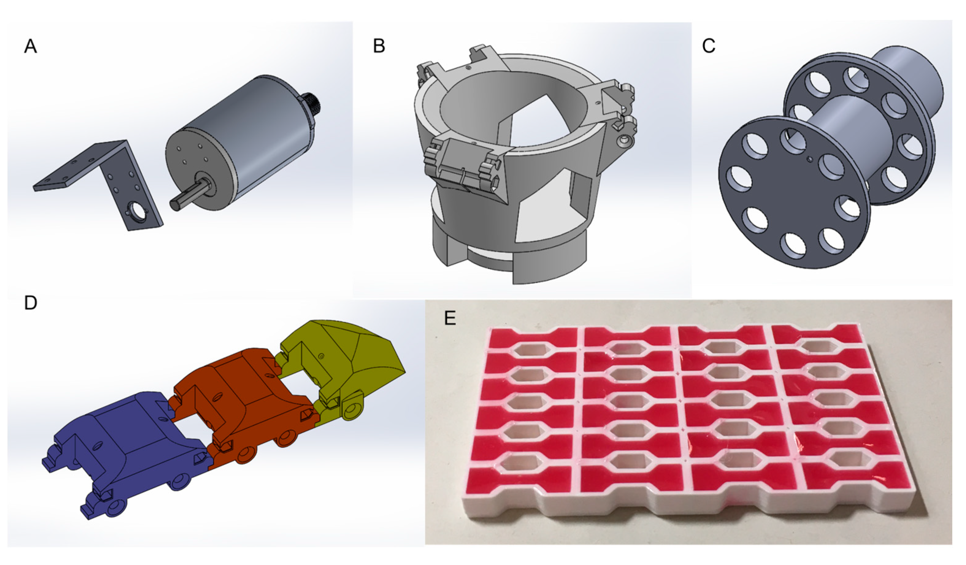
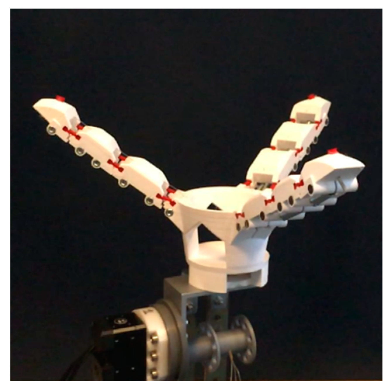
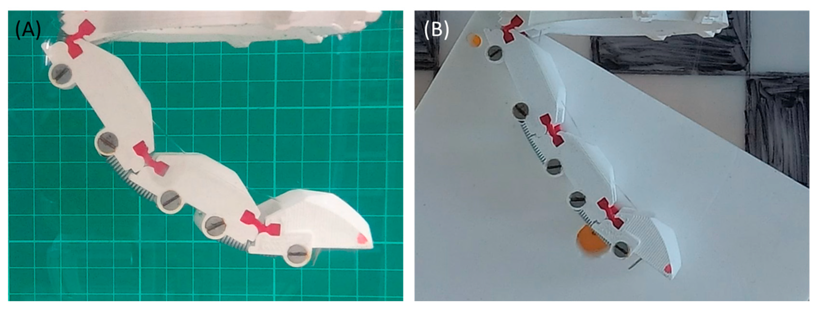
2.2. Mechanical Design and Fabrication

The first phase of the mechanical design of the gripper focused on the individual finger. Similar to human fingers, we have opted for three links to guarantee a trade-off between adaptability to different shapes and low number of components, and respected the same proportionality among phalanges. The compliance to ensure adaptable grasp, both in and out of the bending plane of the finger, was implemented by connecting adjacent links with soft silicone joints. In parallel to the soft joints, we have inserted linear springs to guarantee passive return to an open configuration and to dictate the amount of bending of each joint for a given pulling force exerted by the electric motor. The dimensioning of the springs was guided by a static model of the finger, as depicted in Figure 3.
In the derivation of the model, we have chosen to neglect dynamic effects because of the high damping produced by water, the complexity related to the estimation of joint friction, and because the actuation speed is kept low. We have also neglected gravitational energy because the gripper will be neutrally buoyant and operated underwater. Therefore, the only contributions to the equilibrium configuration of the finger are the tension of the cable and the potential elastic energy stored in the springs with stiffness coefficients K 1 ,   K 2 , and K 3 . The equations describing the joint angles θ 1 , θ 2 , and θ 3 for a given cable tension T are reported in Equation (1), where the torque at each joint depends on r , namely, the distance between the cable and the center of rotation (Figure 3B), and is expressed as τ = r T . From Equation (1), it trivially follows that for each joint, the angle is proportional to the stiffness of the corresponding spring.
{ K 1 θ 1 = τ K 2 θ 2 = τ K 3 θ 3 = τ
Additionally, the forward kinematic model of finger describing the positions of the end effector ( E E ) with respect to the joint angles is reported in Equation (2).
{ x E E = L 1 c o s θ 1 + L 2 cos ( θ 1 + θ 2 ) + L 3 cos ( θ 1 + θ 2 + θ 3 ) y E E = L 1 s i n θ 1 + L 2 c o s ( θ 1 + θ 2 ) + L 3 sin ( θ 1 + θ 2 + θ 3 )
The parameters used in the modelling of the finger are reported in Table 4. Link lengths were selected to mimic the proportions of human phalanges and to comfortably grasp everyday use objects ( [ L 1 , L 2 , L 3 ] = [ 45 ,   40 ,   35 ]   mm ), while cable-joint distance resulted from the design of links ( r = 7   mm ). We have established that the fingertip should be in the desired position p E E d e s = ( x E E d e s , y E E d e s ) = ( 40 ,   110 )   mm for a cable tension T = 4   N compatible with the electric motor selected to actuate the tendon. A 2D schematics of the gripper’s close configuration, which allows precise pinching with the fingertips and enclosing samples within the membrane, is represented in Figure 4. The theoretical angular stiffness values [ K 1 , K 2 , K 3 ] to obtain p E E d e s were obtained by feeding p E E d e s into Equation (2) and inverting it to obtain the angles for the closed configuration [ θ 1 d e s ,   θ 2 d e s , θ 3 d e s ] . The angles were then fed into Equation (1) to retrieve [ K 1 , K 2 , K 3 ] = [ 32.1 ,   100 ,   100 ]   Nmm .
The design of the gripper’s components was realized with the aid of the 3D CAD software Solidworks. The assembly is reported in Figure 2, while the individual drawings of components are reported in Figure 5. The tendon-driven gripper is actuated by a Dynamixel XM430-W350-R smart servomotor (stall torque τ stall = 4.1   Nm ) lodged in a waterproof aluminum canister (Figure 5A) identical to those used in the design of SILVER2 [18]. The canister is attached to the hollow palm (Figure 5B) through a stainless-steel L component. The palm features three attachment structures for the fingers radially arranged at 120°, and 1 mm holes for the tendons. The fingers (Figure 5D), as already mentioned, are made of three phalanges which are connected through soft bow-tie joints (Figure 5E). The use of soft bow-tie joints instead of conventional hinges allows us to improve the fingers’ conformability to different shapes by increasing the compliance in and out of the fingers’ bending planes. Furthermore, it allows us to reduce the number of rotating elements in salt water, which requires higher maintenance efforts. Finally, the motor shaft is connected to a pulley (Figure 5C) with a 20 mm diameter to spool a tendon, which parts into three lines for the actuation of the fingers.
The fabrication of the fingers’ phalanges, palm, and pulley were performed using the Delta Wasp Turbo 2 3D printer. The material chosen was Polylactic acid (PLA) with a density ρ = 1.24   g / cm 3 , a breaking load of 30 MPa, and good resistance to hydrolysis and UV rays. Bow-tie joints were fabricated using an open casting process with the silicone rubber Dragon Skin 20, with a breaking load of 3.8 MPa. For the tendon, we have opted for a nylon fishing line with a 0.6 mm diameter and breaking load of 21.5 kg. The choice of the spring resulted from a trade-off among respecting the theoretical values derived in the previous paragraph, local availability of components, and encumbrances. As angular springs with adequate dimensions and stiffness were not available, we opted for linear springs. Considering a distance d = 5 mm between the center of rotation, located on the bow-tie joint and the axis of the linear spring, the conversion between the angular stiffness values used in the model and the stiffness of the commercially available linear springs used in manufacturing resulted from Equation (3).
K L = K R / d 2
Eventually, for joint 1, we opted for two linear springs in parallel of K = 1 N/mm each, whereas for joints 2 and 3, we opted for just one linear spring with K = 3.2 N/mm. Applying Equation (3) yields a linear stiffness for joint 1 K = 50 Nmm and for joint 2 K = 80 Nmm. The fully assembled prototype, without the elastic membrane, is shown in Figure 6.

3. Results

To characterize the performance of the gripper, we have performed positioning tests, aiming at observing the relation between cable tension and joint angles, and pull-out tests, aiming at characterizing the maximum pull-out force exerted by the gripper for different levels of activations.

3.1. Positioning Tests
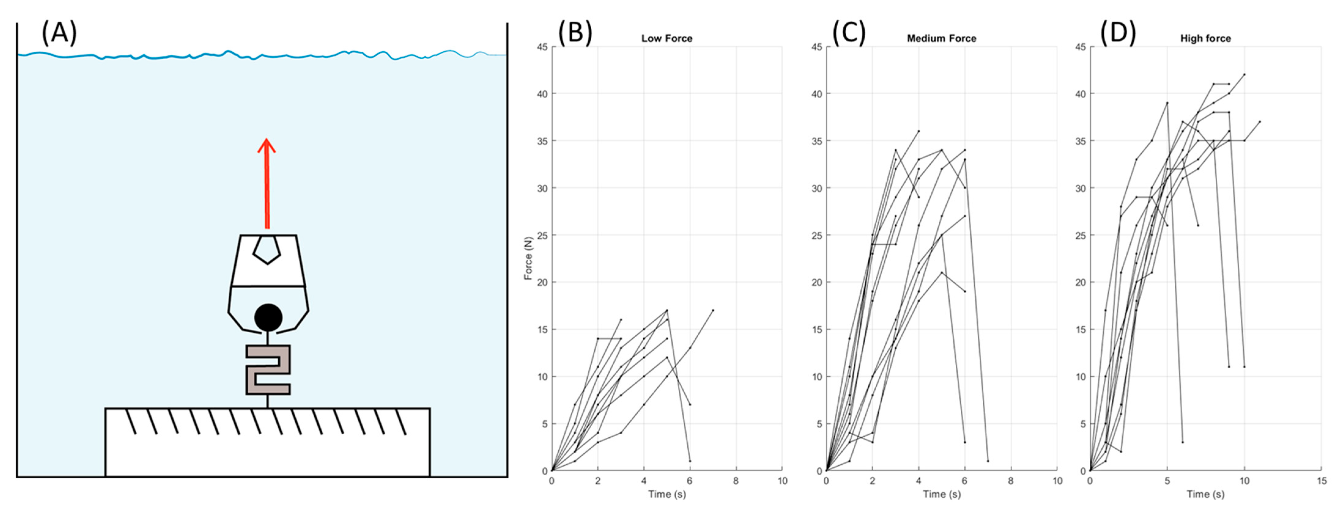
The experimental setup used for positioning tests is shown in Figure 7. The protocol consisted of actuating an individual finger with different input signals, filming its response with a single camera, and extracting the angular trajectory for each joint using the tracking software Kinovea. The experiments were performed in water with the finger vertically aligned (Figure 7A) and on a low friction Polytetrafluoroethylene (PTFE) surface with the finger horizontally aligned (Figure 7B).
The finger was actuated using six different input signals corresponding to a low, medium, and high activation levels, as summarized in Table 5. First, the torque control mode of the Dynamixel smart servomotor was used. This control mode is internally implemented by a Proportional Integral Derivative (PID) controller based on the feedback of a current sensor. The PID parameters used were the default settings, and the output torques were those corresponding to cable tension values of 4.4 N, 5.3 N, and 6.2 N, respectively. Then, the finger was tested in the same conditions using the default position control mode of Dynamixel with three different angular excursions selected to yield joint angles similar to those obtained with the torque control mode. In this case, the angular excursions α corresponded to 44°, 88°, and 132°, respectively.
The results of the positioning tests are shown in Figure 8, where horizontal lines in subplots A, B, and C represent the expected steady state angles computed with Eq 1. For the case of torque-controlled low activation level (Figure 8A), the finger exhibited a very slow dynamics, both in water and on PTFE, and the equilibrium position was not reached after 100 s. On the contrary, the position-controlled low activation level (Figure 8D) resulted in a very fast dynamics which reaches its steady state in slightly more than 1 s. The long setting time observed in the torque-controlled low activation trial is probably due to a high damping compared to the tension of the driving tendon. Indeed, in the torque-controlled medium (Figure 8B) and high (Figure 8C) activation levels the setting times drop to less than two seconds and becomes comparable with the one exhibited by position-controlled trials (Figure 8E,F). The prediction error of the model in Equation (1) for torque control trials resulted smaller for joint angle 1 and larger for joint angles 2 and 3. This result was expected because the ratio of the spring coefficients used in model is different from those eventually integrated in the prototype as reported in Table 4. Performing experiments in water or on PTFE influenced the steady state angles, but no consistent trend was observed. For example, for low and medium activation levels in position control mode Figure 8D,E, joint 1 reaches higher values in water, but this behavior is reversed for high activation levels Figure 8F. The differences between torque- and position-control modes are clearer for low activation levels in which the position control mode yields much faster responses (Figure 8A,D); however, the torque-control mode appeared to be less reliable and more prone to repeatability issue. Furthermore, the position-control mode allows to set the rotation speed, and consequently, the time to close the fingers. This latter point can be a useful feature during field operations, and thus, the position control mode was selected for the pull-out tests.

3.2. Pull-Out Tests

The experimental setup for pull-out tests is depicted in Figure 9A. A load cell was fixed to the bottom of a small tank filled with fresh water while a spherical handle is attached on the other end of the load cell. Each trial consisted of grasping the handle with the gripper with three increasing activation values and manually pulling the gripper with non-controlled velocity while measuring the force on the load cell with acquisition frequency of 1 Hz. With respect to the positioning tests reported in the previous section, the actuation values selected were higher, namely, 132° for low activation, 176° for medium activation, and 212° for high activation. A total of 10 trials per activation value were performed. The pull-out force vs. time obtained is reported in Figure 9B. All curves present similar trends with the force increasing to a maximum, then dropping to zero when the grasp is lost. Naturally, higher activation levels resulted in higher pull-out forces as reported in Table 6.

4. Discussion and Conclusions

In this work, we have presented the design, fabrication, and testing of an underwater gripper for the collection of litter and biological sampling. To systematically account for the requirements of different end-users and developers, we have resorted to design tools often used in industry for product design, namely the HoQ and Pugh decision matrix. Through a series of interviews with end users, we have collected a set of 20 requirements and evaluated their importance from the perspective of the developers, the principal investigator in charge of the experimental campaign, and the mission operator. This procedure highlighted the trade-off between the expected performance and practical aspects related to simplicity of use, integration with underwater vehicles, assembly, and maintenance. Subsequently, we have evaluated the closest prototypes in the state-of-the-art with respect to our requirements to select a reference design. Finally, we have proposed eight concept design ideas and evaluated them against the reference prototype to come up with the final conceptual design. Although normally used in industrial contexts, the HoQ and Pugh matrix are very powerful tools for applied robotics research. In fields, such as marine science, where new technologies are critical to push the boundaries of scientific research and exploration, the different backgrounds and jargon between developers and end-users may result in excessive expectations by the latter, or in the development of complex prototypes which are impractical for the field. The application of systematic design tools, such as the one proposed herein, have the potential of fostering more fruitful and clear interdisciplinary collaborations with the ambition of providing useful and innovative tools to the scientific community.
For the case study presented in this paper, the requirements related to pre- and post- mission phases, dealing with simplicity of manufacturing, assembly, transportation, and maintenance, were tackled by resorting to a soft-robotic approach based on an underactuated cable driven actuation. As reported in the Mechanical design and fabrication section, the gripper presents a very simple design which can be implemented with a fused deposition modelling (FDM) 3D printer and silicone casting. Once all components are manufactured, the gripper can be assembled in less than 10 min, thus allowing for in situ assembly, adaptations, or repairing. With respect to the mission requirements, the versatility to perform different types of grasps, including pinching, power grasps, and caging, was obtained through the radial arrangement of the fingers, and the integration of an elastomeric membrane and a hollow palm to favor the envelopment of small samples or sediment debris. The compliance of the bow-tie joints made the fingers more adaptable to different shapes and delicate. At the same time, the cable driven actuation, as shown by the pull-out tests results, allowed a good degree of force modulation that can be useful when a target is stuck or anchored to the seabed. Moreover, the forces exerted by the fingers and their kinematics can be modulated by simply replacing the springs and bow-tie joints, thus increasing the versatility of the gripper for reduced costs.
Soon, the gripper will be integrated on the ULR SILVER2 and on other available underwater robots to validate its use in the field targeting sunken pieces of litter, for example, tin cans or plastic bottles, and benthic organisms, such as sea urchins, soft corals, or holothurians, and even samples of sandy/muddy sediments.

Author Contributions

Conceptualization, M.C. (Marcello Calisti), G.C and M.C. (Matteo Cianchetti); methodology, M.C. (Marcello Calisti), G.C. and M.C. (Matteo Cianchetti); software, M.D.L.; validation, M.D.L. and M.C. (Marcello Calisti); formal analysis, M.D.L. and G.P.; investigation, M.D.L., G.P., G.C. and M.C. (Marcello Calisti); resources, M.C. (Marcello Calisti) and M.C. (Matteo Cianchetti); data curation, M.D.L. and G.P.; writing—original draft preparation, G.P.; writing—review and editing, G.P., G.C. and M.C. (Marcello Calisti); visualization, G.P.; supervision, M.C. (Marcello Calisti) and M.C. (Matteo Cianchetti); project administration, M.C. (Marcello Calisti); funding acquisition, M.C. (Marcello Calisti) and M.C. (Matteo Cianchetti). All authors have read and agreed to the published version of the manuscript.

Funding

This research was funded by the National Geographic Society (grant agreement No. NGS-56544T-19) and by the Agencia de Gestión de Ayudas Universitarias y de Investigación (AGAUR) of the Generalitat de Catalunya through the Beatriu de Pinos postdoctoral fellowship program (grant number 2021 BP 00039).

Institutional Review Board Statement

Not applicable.

Informed Consent Statement

Not applicable.

Data Availability Statement

No new data were created.

Conflicts of Interest

The authors declare no conflict of interest.

References

  1. Petillot, Y.R.; Antonelli, G.; Casalino, G.; Ferreira, F. Underwater Robots: From Remotely Operated Vehicles to Intervention-Autonomous Underwater Vehicles. IEEE Robot. Autom. Mag. 2019, 26, 94–101. [Google Scholar] [CrossRef]
  2. Directive 2008/56/EC of the European Parliament and of the Council of 17 June 2008 Establishing a Framework for Community Action in the Field of Marine Environmental Policy (Marine Strategy Framework Directive). Available online: https://eur-lex.europa.eu/legal-content/EN/TXT/?uri=celex%3A32008L0056 (accessed on 28 March 2023).
  3. Huang, H.; Tang, Q.; Li, J.; Zhang, W.; Bao, X.; Zhu, H.; Wang, G. A review on underwater autonomous environmental perception and target grasp, the challenge of robotic organism capture. Ocean. Eng. 2020, 195, 106644. [Google Scholar] [CrossRef]
  4. Carrera, A.; Palomeras, N.; Hurtós, N.; Carreras, M. Free-floating panel intervention by means of Learning by Demonstration. IFAC-PapersOnLine 2015, 48, 38–43. [Google Scholar] [CrossRef]
  5. Oussama, K.; Xiyang, Y.; Gerald, B.; Brian, S.; Boyeon, K.; Shameek, G.; Hannah, S.; Shiquan, W.; Mark, C.; Aaron, E.; et al. Ocean one: A robotic avatar for oceanic discovery. IEEE Robot. Autom. Mag. 2016, 23, 20–29. [Google Scholar] [CrossRef]
  6. Mazzeo, A.; Aguzzi, J.; Calisti, M.; Canese, S.; Vecchi, F.; Stefanni, S.; Controzzi, M. Marine Robotics for Deep-Sea Specimen Collection: A Systematic Review of Underwater Grippers. Sensors 2022, 22, 648. [Google Scholar] [CrossRef] [PubMed]
  7. Teoh, Z.E.; Phillips, B.T.; Becker, K.P.; Whittredge, G.; Weaver, J.C.; Hoberman, C.; Gruber, D.F.; Wood, R.J. Rotary-actuated folding polyhedrons for midwater investigation of delicate marine organisms. Sci. Robot. 2018, 3, eaat5276. [Google Scholar] [CrossRef] [PubMed]
  8. Sinatra, N.R.; Teeple, C.B.; Vogt, D.M.; Parker, K.K.; Gruber, D.F.; Wood, R.J. Ultragentle manipulation of delicate structures using a soft robotic gripper. Sci. Robot. 2019, 4, eaax5425. [Google Scholar] [CrossRef] [PubMed]
  9. Manti, M.; Hassan, T.; Passetti, G.; d’Elia, N.; Cianchetti, M.; Laschi, C. An Under-Actuated and Adaptable Soft Robotic Gripper. In Biomimetic and Biohybrid Systems: 4th International Conference, Living Machines 2015, Barcelona, Spain, 28–31 July 2015, Proceedings 4; Springer International Publishing: Berlin/Heidelberg, Germany, 2015; pp. 64–74. [Google Scholar] [CrossRef]
  10. Mura, D.; Barbarossa, M.; Dinuzzi, G.; Grioli, G.; Caiti, A.; Catalano, M.G. A Soft Modular End Effector for Underwater Manipulation: A Gentle, Adaptable Grasp for the Ocean Depths. IEEE Robot. Autom. Mag. 2018, 25, 45–56. [Google Scholar] [CrossRef]
  11. Palli, G.; Moriello, L.; Scarcia, U.; Melchiorri, C. An Underwater Robotic Gripper with Embedded Force/Torque Wrist Sensor. IFAC-PapersOnLine 2017, 50, 11209–11214. [Google Scholar] [CrossRef]
  12. Stuart, H.; Wang, S.; Khatib, O.; Cutkosky, M.R. The Ocean One hands: An adaptive design for robust marine manipulation. Int. J. Rob. Res. 2017, 36, 150–166. [Google Scholar] [CrossRef]
  13. Galloway, K.C.; Becker, K.P.; Phillips, B.T.; Kirby, J.; Licht, S.; Tchernov, D.; Wood, R.J.; Gruber, D.F.; Shen, Z.; Zhong, H.; et al. Soft Robotic Grippers for Biological Sampling on Deep Reefs. Soft Robot 2016, 3, 23–33. [Google Scholar] [CrossRef] [PubMed]
  14. Backus, S.; Onishi, R.; Bocklund, A.; Berg, A.; Contreras, E.; Parness, A. Design and testing of the JPL-Nautilus Gripper for deep-ocean geological sampling. J. Field Robot. 2020, 37, 972–986. [Google Scholar] [CrossRef]
  15. Kumamoto, H.; Shirakura, N.; Takamatsu, J.; Ogasawara, T. Underwater Suction Gripper for Object Manipulation with an Underwater Robot. In Proceedings of the 2021 IEEE International Conference on Mechatronics (ICM), Kashiwa, Japan, 7–9 March 2021; pp. 1–7. [Google Scholar] [CrossRef]
  16. Mazzeo, A.; Aguzzi, J.; Calisti, M.; Canese, S.; Angiolillo, M.; Allcock, A.L.; Vecchi, F.; Stefanni, S.; Controzzi, M. Marine Robotics for Deep-Sea Specimen Collection: A Taxonomy of Underwater Manipulative Actions. Sensors 2022, 22, 1471. [Google Scholar] [CrossRef] [PubMed]
  17. Gruber, D.F.; Wood, R.J. Advances and future outlooks in soft robotics for minimally invasive marine biology. Sci. Robot. 2022, 7, eabm6807. [Google Scholar] [CrossRef] [PubMed]
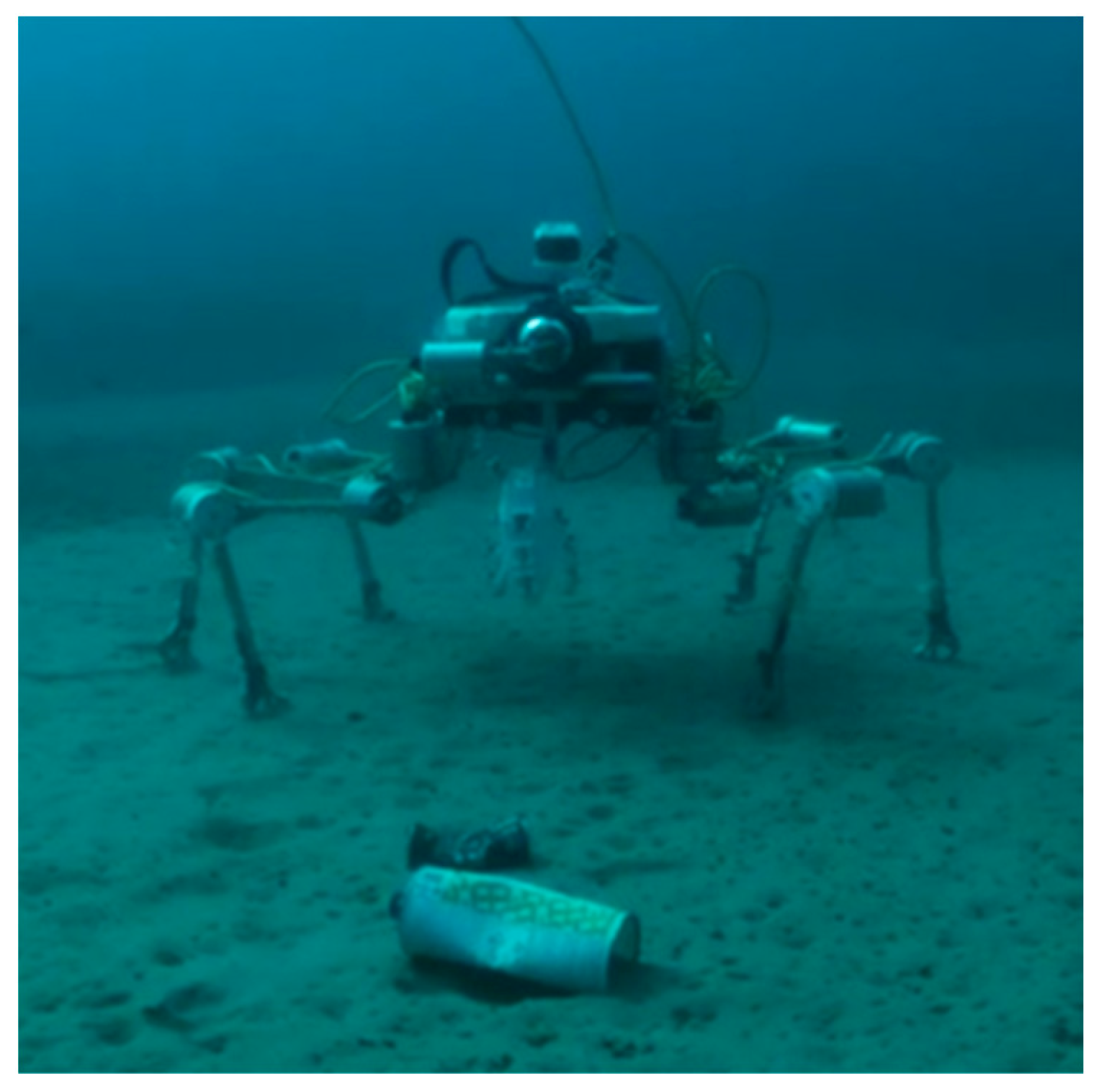
  18. Picardi, G.; Chellapurath, M.; Iacoponi, S.; Stefanni, S.; Laschi, C.; Calisti, M. Bioinspired underwater legged robot for seabed exploration with low environmental disturbance. Sci. Robot. 2020, 5, eaaz1012. [Google Scholar] [CrossRef] [PubMed]
  19. Belhe, U.; Kusiak, A. The house of quality in a design process. Int. J. Prod. Res. 1996, 34, 2119–2131. [Google Scholar] [CrossRef]
  20. Guler, K.; Petrisor, D.M. A Pugh Matrix based product development model for increased small design team efficiency. Cogent Eng. 2021, 8, 1923383. [Google Scholar] [CrossRef]
  21. Birk, A.; Antonelli, G.; Di Lillo, P.; Simetti, E.; Casalino, G.; Indiveri, G.; Ostuni, L.; Turetta, A.; Caffaz, A.; Weiss, P.; et al. Dexterous Underwater Manipulation from Onshore Locations: Streamlining Efficiencies for Remotely Operated Underwater Vehicles. IEEE Robot. Autom. Mag. 2018, 25, 24–33. [Google Scholar] [CrossRef]
  22. Ullman, D.G. The Mechanical Design Process; McGraw Hill: New York, NY, USA, 1992; Volume 2. [Google Scholar]
Figure 1. The Underwater Legged Robot (ULR) SILVER2 equipping the cable-driven gripper presented in this work.
Jmse 11 00771 g001
Figure 2. CAD of the gripper showing the main components.
Jmse 11 00771 g002
Figure 3. (A) Model of the finger. (B) Schematic of the finger.
Jmse 11 00771 g003
Figure 4. 2D Schematics of the gripper in the closed configuration for which the fingertips touch each other in the point ( x d e s , y d e s ) .
Jmse 11 00771 g004
Figure 5. Components of the gripper. (A) Waterproof motor canister with attachment for the palm. (B) Hollow palm. (C) Pulley. (D) Finger made of three phalanges with slots for bow-tie joints, tendon, and springs. (E) Bow-tie joints before demolding.
Jmse 11 00771 g005
Figure 6. Gripper prototype in open position. The elastic membrane is not shown.
Jmse 11 00771 g006
Figure 7. Position test setup in water (A) and on PTFE (B).
Jmse 11 00771 g007
Figure 8. Positioning test results with torque-control and position-control modes. Tests in water are plotted in black, and tests on PTFE are plotted in red. Joint angle trajectories for three increasing values of cable tension T = 4.4 N (A), T = 5.3 N (B), and T = 6.2 N (C). Horizontal lines correspond to theoretical values obtained from Equation (1). Joint angle trajectories for three increasing values of motor angle α = 44 ° (D), α = 88 ° (E), and α = 132 °   (F).
Jmse 11 00771 g008
Figure 9. Experimental setup and results of pull-out tests. (A) Experimental setup. The gripper, holding a spherical object connected to a load cell on the bottom of the tank, is pulled with non-controlled velocity for three increasing values of pulley angle. (B) Results for the low force activation. (C) Results for the medium force activation. (D) Results for the high force activation.
Jmse 11 00771 g009
Table 1. Requirements for the development of the soft gripper resulting from interviews with the team of developers, a marine scientist, and a mission operator/ROV pilot. Five prototypes in the state-of-the-art [9,10,12,13,21] have been evaluated against the requirements collected, and the Ocean One hand [12] obtained the highest score.
WhoNow
Team SILVER2Marine ScientistMission Operator1 = Poor
5 = Excellent
● Stuart et al. [12]
■ Galloway et al. [13]
▲ Manti et al. [9]
✦ Mura et al. [10]
✻ Birk et al. [21]
What12345
Pre-missionR1. Simple manufacturing522■ ✦
R2. Simple transportation736 ✻ ■● ▲ ✦
R3. Simple assembly636■ ✦
R4. Handy846 ● ✻ ✦
MissionR5. Easy to use338 ✦ ✻● ■ ▲
R6. Grasping different shapes463 ■ ✦
R7. Collecting sand/sediment samples563● ■ ▲ ✦ ✻
R8. Collecting biological samples483 ✻ ▲✦ ●
R9. Firm grasp767 ▲ ✦● ■
R10. Not damaging grasped objects674 ● ■ ▲
R11. Collecting stuck or anchored samples485 ✦ ✻
R12. Not damaging working environment484 ● ■ ▲ ✦
R13. Dexterous grasp457 ✻ ■● ✦
R14. Not getting stuck in the environment447● ✦■ ▲
R15. Long battery447 ● ✦ ✻
R16. Not introducing pollutants473 ■ ✻● ▲ ✦
Post-missionR17. Simple disassembly526 ■ ✦ ✻
R18. Simple ordinary maintenance666● ✦
R19. Simple extra-ordinary maintenance745■ ✦
R20. Usable in different application scenarios342 ■ ▲● ✦ ✻
100100100
total ●:80
total ■:73
total ▲:71
total ✦:70
total ✻:54
Table 2. Eight conceptual designs proposed to meet the requirement expressed by the end-users.
1. Replica of the Ocean One hand [13] with membranes2. Two-fingered gripper with hollow fingertips3. Gripper inspired to the carnivorous plant Dionaea muscipula4. Gripper with soft distal phalanges
Jmse 11 00771 i001Jmse 11 00771 i002Jmse 11 00771 i003Jmse 11 00771 i004
5. Grab with soft claws actuated by an endless screw6. Cable-driven gripper inspired by crab claws7. Hydraulic soft gripper [13]8. Radially symmetric three-fingered gripper with hollow palm and membranes
Jmse 11 00771 i005Jmse 11 00771 i006Jmse 11 00771 i007Jmse 11 00771 i008
Table 3. Decision matrix for the design of the underwater gripper presented in this work. The concept design ideas are evaluated with respect to a reference design, then weighted using the stakeholders ratings, which reflect the relative importance of individual requirements. The final score is obtained by summing the totals weighted for all stakeholders.
WhatWhoReferenceConcept Design Ideas
Team
SILVER2
Marine ScientistMission OperatorOcean One Hand(1) Ocean One Hand with Membranes(2) Two-Fingered Gripper with Hollow Fingertips(3) Carnivorous Plant Inspired Gripper(4) Gripper with Soft Distal Phalanges(5) Grab with Soft Claws and Endless Screw Actuation(6) Crab Claw Inspirred Gripper with Cable-Driven Actuation(7) Hydraulic Soft Gripper(8) Radially Symmetric Gripper with Hollow Palm and Membranes
Pre-missionR1. Simple manufacturing522Datum−1−1−100−1−1−1
R2. Simple transportation73601100010
R3. Simple assembly636−111−1−101−1
R4. Handy84601111101
MissionR5. Easy to use338000000−10
R6. Grasping different shapes46310−10−1000
R7. Collecting sand/sediment samples56321211112
R8. Collecting biological samples48310000001
R9. Firm grasp7671−1−100−1−11
R10. Not damaging grasped objects6740−1−100000
R11. Collecting stuck or anchored samples48500−100000
R12. Not damaging working environment48400100020
R13. Dexterous grasp45700000000
R14. Not getting stuck in the environment44700000000
R15. Long battery44700000000
R16. Not introducing pollutants47300000000
Post-missionR17. Simple disassembly526000−10000
R18. Simple ordinary maintenance66600000000
R19. Simple extra-ordinary maintenance745−1000000−1
R20. Usable in different application scenarios34211001101
100100100Total32101123
Total weighted on Team SILVER2101192641114
Total weighted on Marine scientist27515561725
Total weighted on Mission operator8107−322611
Overall total weighted452617413123450
Table 4. Parameters used in the modelling of the finger.
ParametersSymbolValue
Link lengths [ L 1 , L 2 , L 3 ] [ 45 ,   40 ,   35 ]   mm
Cable-joint distance r 7   mm
Fingertip position at closed configuration p E E d e s = ( x E E d e s , y E E d e s ) ( 40 ,   110 )   mm
Joint angles at closed configuration [ θ 1 d e s ,   θ 2 d e s , θ 3 d e s ] [ 50 ,   16 ,   16 ]   °
Cable tension at closed configuration T 4   N
Theoretical angular spring stiffness [ K 1 , K 2 , K 3 ] [ 32.1 ,   100.3 ,   100.3 ]   Nmm
Bow-tie joint spring distance d 5   mm
Theoretical linear spring stiffness [ K 1 l i n ,   K 2 l i n , K 3 l i n ] [ 1.3 ,   4 ,   4 ]   N / mm
Table 5. Inputs used in positioning tests.
Activation ModeLow ActivationMedium ActivationHigh Activation
Torque controlT = 4.4 NT = 5.3 NT = 6.2 N
Position controlα = 44°α = 88°α = 132°
Table 6. Maximum pull-out force (mean and variance) for three increasing values of activation.
Low ActivationMedium ActivationHigh Activation
Position controlα = 132°α = 176°α = 212°
Maximum pull-out forceF = 14.7 ± 1.95 NF = 30.3 ± 4.8 NF = 37 ± 3.7 N
Disclaimer/Publisher’s Note: The statements, opinions and data contained in all publications are solely those of the individual author(s) and contributor(s) and not of MDPI and/or the editor(s). MDPI and/or the editor(s) disclaim responsibility for any injury to people or property resulting from any ideas, methods, instructions or products referred to in the content.

