Article

Study Method of Pile near Cohesionless Slope under Reversed Lateral Load Considering Sand Strength State and Lateral Deflection of Pile

School of Resources and Safety Engineering, Central South University, Changsha 410083, China
*
Author to whom correspondence should be addressed.
J. Mar. Sci. Eng. 2023, 11(4), 741; https://doi.org/10.3390/jmse11040741
Submission received: 1 March 2023 / Revised: 21 March 2023 / Accepted: 27 March 2023 / Published: 29 March 2023

Abstract

:
A p-y curve method of pile near cohesionless soil slope under reversed lateral load is proposed. This method takes into account the failure mode of soil around the pile under reversed lateral load and the interaction mode between pile and soil, and derives the ultimate soil resistance of the pile. Considering the change of the original stress state of soil due to the lateral deflection of the pile foundation, the influence of the relative density, the initial mean effective stress and the lateral deflection of pile foundation on the internal friction angle of the sand is evaluated to further accurately calculate the soil resistance value at each depth. The prediction results of this method are well verified by comparing with the FE results and centrifuge test results. Finally, the influence of the process of lateral deflection of pile on the strength state of soil around the pile and the bearing capacity of pile is studied.

1. Introduction

In recent years, rapid economic development has promoted the construction of infrastructures such as bridges, base stations, offshore wind turbines and high-speed railways, which often need to bear lateral loads caused by waves, wind and earthquakes [1,2]. Pile foundation has good performance and becomes the preferred foundation type for these structures [3]. In areas dominated by sloping terrain, the site selection of pile foundation is inevitably built on slope or near slope. Due to the existence of the slope, the soil on both sides of the pile foundation is no longer a symmetrical system, which makes the pile-soil system have obvious asymmetry. At the same time, the process of lateral deflection of pile foundation under lateral load can change the original stress state of soil around pile. Therefore, the lateral bearing mechanism of pile foundation near slope considering the soil strength state should be paid more attention.
At present, scholars have done certain research on the influence of slope on the bearing capacity of pile [4,5,6,7]. Chae et al. [6] made a numerical analysis of pile near the cohesionless slope and pointed out that the closer a pile is to the slope crest, the smaller the lateral soil resistance of pile. Mezazigh and Levacher [4] proposed to use the reduction coefficient ( p -multipiler) to describe the influence of slope angle and distance from pile to slope top on lateral soil resistance p . Lin et al. [7] considered the weakening effect of slope on soil resistance and deduced the ultimate soil resistance solution of piles near sand slopes. Unfortunately, the mentioned research on pile foundations near cohesionless slopes is all on cases where the loading direction is from the horizontal ground side to the slope side [see Figure 1a]. The bearing mechanism of piles near the cohesionless slope under the reverse loading direction [see Figure 1b] has received little attention from scholars.
It is worth noting that for cohesionless soil, the internal friction angle has a great influence on lateral soil resistance p , and it is very important to select an appropriate internal friction angle value to evaluate the bearing capacity of the pile [8,9]. However, it is obviously inappropriate to use a certain internal friction angle as the internal friction angle of sand in the whole buried depth range of pile to calculate the lateral resistance when evaluating the lateral bearing capacity of pile in sand previously reported. Bolton [10] and Chakraborty and Salgado [11] proposed that the internal friction angle of sand depends on its critical-state friction angle, the relative density and the mean effective stress under peak shear strength. Yang and Mu [12] further pointed out that from the perspective of the constitutive model, the internal friction angle should be related to the initial mean effective stress, rather than the mean effective stress under the peak shear strength. However, they all ignored that the sand will be squeezed by the lateral deflection of the pile under the lateral load, thus changing the original stress level of the sand.
To this end, this study will propose a new p-y curve model to describe the lateral load transfer behavior of piles near cohesionless soil slopes under the action of reverse loading direction. According to the action of reversed lateral load, the soil in front of and behind the pile will be divided into a passive wedge and active wedge for consideration. In addition, the influence of slope on the active wedge behind the pile is also considered, so there are two failure modes. Then, the ultimate lateral bearing capacity of pile under this condition is obtained. Meanwhile, the influence of pile lateral deflection on the stress level of sand is considered in the process of reversed lateral load. The influence of critical-state friction angle, relative density and initial mean effective stress on internal friction angle is analyzed to accurately calculate the lateral resistance of soil. Finally, a centrifuge test and FE analysis results are used to evaluate the feasibility of this method and the influence of sand state-related strength on pile design is discussed.

2. Analysis of Proposed Method

As shown in Figure 2, a pile with a total length of L + h and a diameter of   D is installed near the cohesionless slope, the distance from pile center to slope top is b and the slope angle is θ . The buried depth of pile is L , and the height from the point where the lateral load acting on pile to the horizontal ground is h . The action direction of lateral load H 0 is from the slope behind the pile to the horizontal ground in front of the pile. Under the action of H 0 , the pile body will move to the left and continuously squeeze the left soil mass, while the soil behind the pile will actively move forward with the shift of the pile, thus forming an active state. When the soil reaches the ultimate state, the passive wedge failure and the active wedge failure occur in the soil in front of and behind the pile, respectively. Due to the existence of slope topography, the failure surface of the active wedge behind the pile has not developed to the slope when the load H 0 is small [see Figure 2a], but when the load H 0 is large, the failure surface of active wedge will develop to the slope [see Figure 2b], and the active wedge behind the pile formed at this time is different from the previous one, which needs to be considered separately.
We define the lateral passive resistance generated by this passive wedge in front of pile as F p , and the lateral active resistance generated by the active wedge behind the pile as F a , so the total lateral resistance generated by the soil ( F t o t ) can be expressed as
F t o t = F p F a

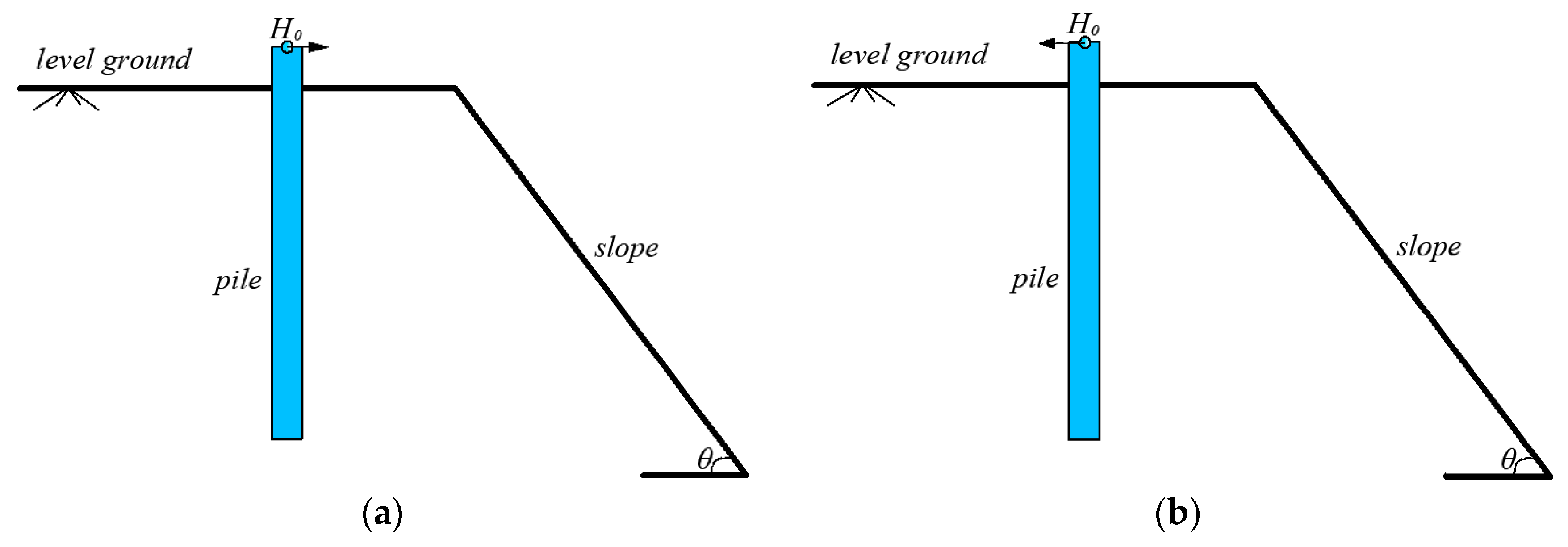
2.1. Basic Assumptions

(1) The cohesionless slope is stable.
(2) The active wedge failure of the soil behind the pile conforms to Coulomb’s law.
(3) The passive wedge failure of the soil in front of the pile conforms to the Mohr–Coulomb law [7].

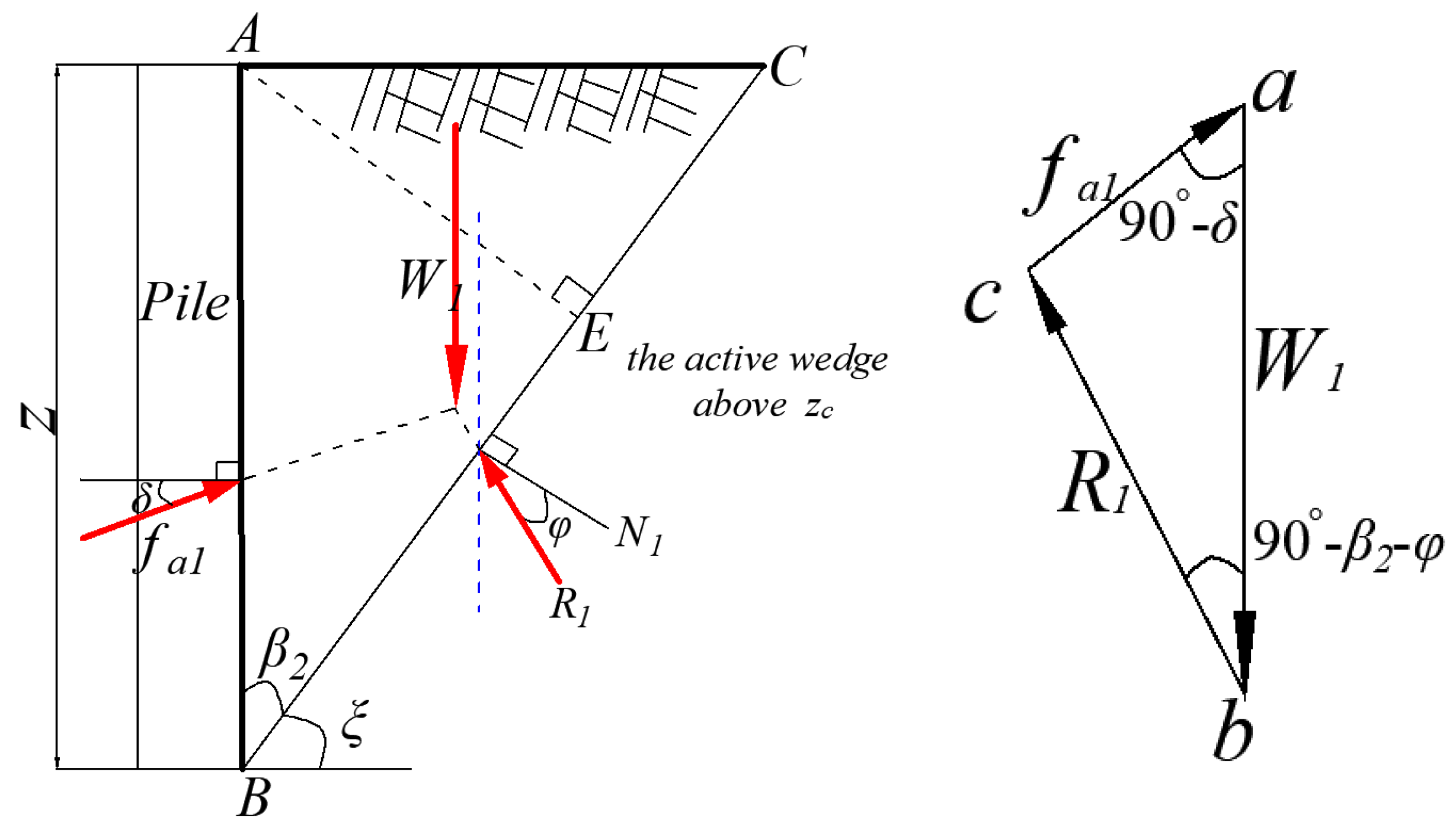
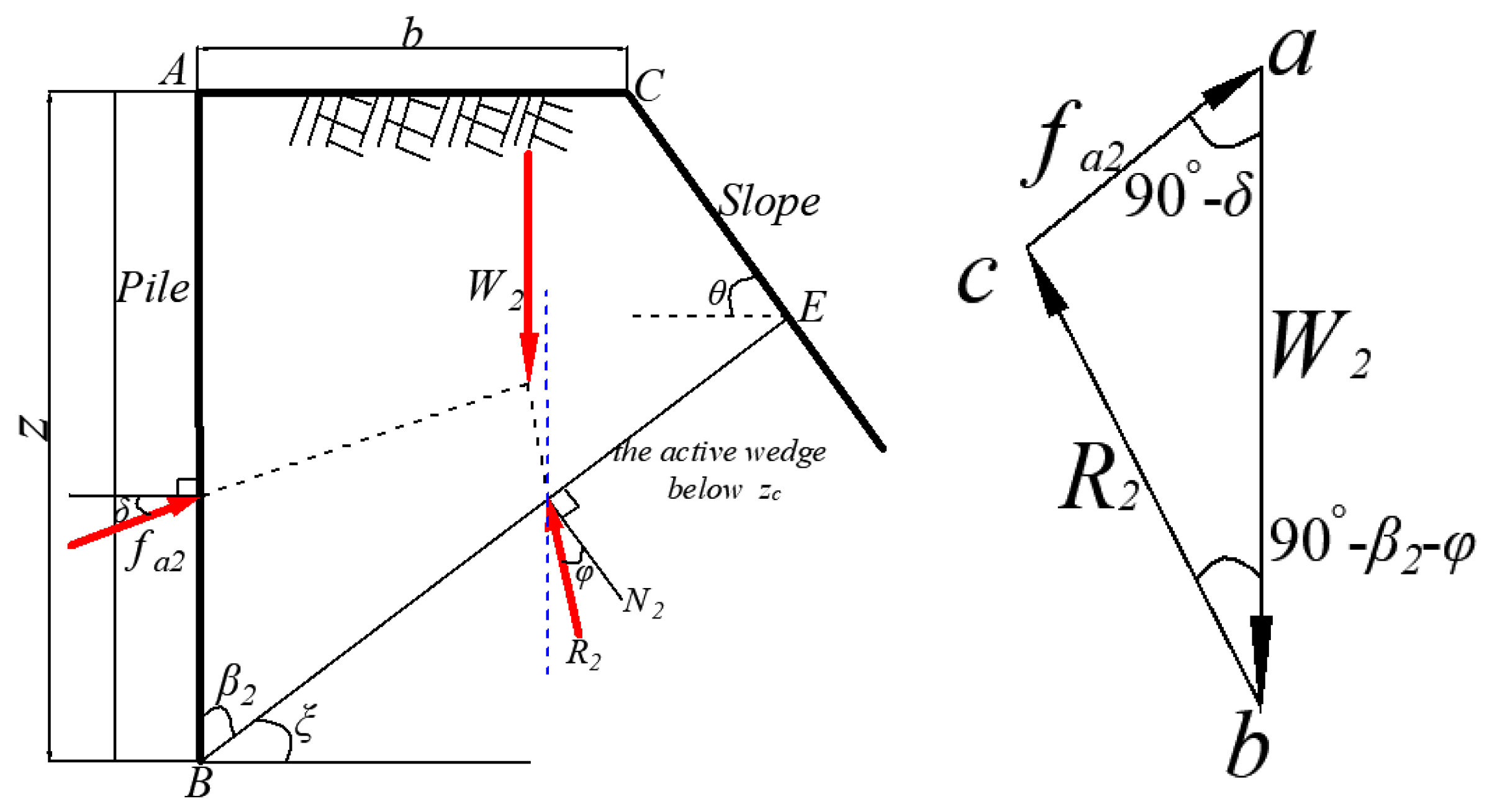
2.2. Force Analysis of Active Wedge

There are two failure modes of the active wedge behind the pile, as shown in Figure 2a,b. We define the critical depth of these two failure modes as z c , and according to the geometric relation, z c can be expressed as
z c = b t a n β 2
where β 2 is the bottom angle of active wedge behind the pile and β 2 = 45 ° φ 2 ; φ is the internal friction angle of cohesionless soil.
The active force F a formed by the active wedge behind the pile can be calculated according to Coulomb’s active earth pressure theory. Figure 3 shows the system of acting force and the two-dimensional plane of the active wedge behind the pile.
The geometric shape of the active wedge is determined by β 2 and depth z . The forces generated on the active wedge include: the unit active resistance f a 1 generated by the pile against the active wedge behind the pile, the unit reaction R 1 at the failure shear BC and the unit weight W 1 generated by the soil. The angle from the action direction of unit reaction R 1 to the vertical line of BC is φ . Therefore, according to the force balance in horizontal and vertical direction, the following equations can be established:
In the horizontal direction, the balance equation is expressed as
f a 1 c o s δ = R 1 s i n 90 ° φ β 2
In the vertical direction, the balance equation is expressed as
f a 1 s i n δ + R 1 c o s 90 ° φ β 2 = W 1
According to Equations (3) and (4), we can obtain
f a 1 s i n δ + f a 1 c o s δ s i n φ + β 2 c o s φ + β 2 = W 1
Therefore,
f a 1 = W 1 c o s φ + β 2 s i n δ + φ + β 2
The unit weight W 1 of active wedge is expressed as
W 1 = S 1   ·   γ = 1 2 γ t a n β 2 z 2
By Equations (6) and (7), the unit lateral active force f a 1 above critical depth z c can be obtained.
f a 1 = 1 2 γ t a n β 2 c o s φ + β 2 s i n δ + φ + β 2 z 2
As shown in Figure 4, with the increase in H 0 , the failure shear band BE of active wedge behind the pile develops to the slope. At this time, the lateral active resistance generated by the active wedge behind the pile will be affected by this slope, so it is necessary to further modify Coulomb’s active earth pressure theory to accurately evaluate the lateral active resistance in this case. Figure 4 shows the active wedge formed when the shear failure zone develops below the critical depth z c . The shape of active wedge is determined by β 2 , depth z , distance from pile center to slope top b and slope angle θ . In addition, the forces generated on the active wedge include: the unit active resistance f a 2 generated by the pile against the active wedge behind the pile, the unit reaction R 2 at the failure shear band BE and the unit weight W 2 generated by the soil.
Similarly, according to the force balance acting on active wedge, we can obtain
f a 2 c o s δ = R 2 s i n 90 ° φ β 2
f a 2 s i n δ + R 2 c o s 90 ° φ β 2 = W 2
Therefore,
f a 2 = W 2 c o s φ + β 2 s i n δ + φ + β 2
The unit weight W 2 of the active wedge is expressed as
W 2 = S 2   ·   γ
The area S 2 is calculated according to the geometric shape of the active wedge shown in Figure 4 and is expressed as
S 2 = t a n β 2 2 1 + t a n θ t a n β 2 z 2 + b t a n θ t a n β 2 1 + t a n θ t a n β 2 z b 2 t a n θ 2 1 + t a n θ t a n β 2
Therefore, the lateral active resistance F a can be expressed as
F a = F a 1 = f a 1   ·   D = 1 2 γ D t a n β 2 c o s φ + β 2 s i n δ + φ + β 2 z 2                   z z c F a 2 = f a 2   ·   D = W 2 D c o s φ + β 2 s i n δ + φ + β 2                                                 z > z c  

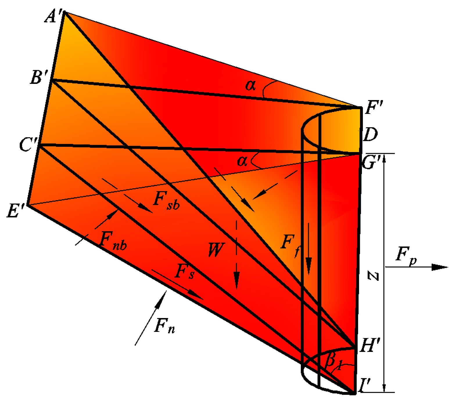
2.3. Force Analysis of Passive Wedge

As shown in Figure 5, the three-dimensional geometry of the passive wedge in front of the pile [7,13,14], the lateral passive resistance F p generated by the passive wedge in front of the pile against the pile, is mainly provided by the combined action of the weight W of the passive soil wedge, the vertical friction between pile and soil F f , the normal force F n and the shear force F s on both sides of the wedge, and the normal force F n b and the shear force F s b of the bottom of wedge. Under the action of H 0 , this passive wedge in front of the pile will continuously develop towards deeper soil, and will expand forward at an angle of α in the horizontal direction. Bowman [15] suggested that the α of dense sand be φ / 2 ~ φ , and α of loose sand be φ / 3 ~ φ / 2 . This bottom angle between the failure surface A E I H and the vertical direction is β 1 . The bottom angle β 1 is determined as β 1 = 45 ° + φ / 2 according to the Mohr–Coulomb strength theory.
From the equilibrium of the forces in the horizontal direction, we can get
F p = 2 F s c o s α s i n β 1 + F s b s i n β 1 + F n b c o s β 1 2 F n s i n α
The shear force F s and F s b are calculated according to the Mohr–Coulomb criterion. The weight of the passive soil wedge W , the normal force F n and the shear force F s on both sides of the wedge, and the normal force F n b and the shear force F s b of the bottom of the wedge are expressed as
F n = 1 6 K 0 γ z 3 t a n β 1 s e c α
F s = F n t a n φ
W = 1 3 z 3 γ t a n 2 β 1 t a n α + 1 2 z 2 γ D t a n β 1
F n b = 1 3 γ t a n 2 β 1 t a n α + K 0 γ s i n β 1 t a n φ z 3 + 1 2 γ D z 2 t a n β 1 s i n β 1 c o s β 1 t a n φ
F s b = F n b t a n φ
F f = γ π D t a n δ z 2 6
where δ is the interface friction angle between soil and pile, δ = 0.5∼0.7 φ (steel pipe pile) or δ = 1.0 φ (bored pile) [16].
Then, the total lateral resistance F t o t can be obtained by combining Equations (1)–(21), and the ultimate soil resistance per unit depth p u can be obtained by using F t o t to differentiate the depth z . Therefore, p u is expressed as
p u = p u 1 = q 1 z 2 + p 1 z                   z z c p u 2 = q 2 z 2 + p 2 z + m 2                       z > z c  
where
q 1 = q 2 = t a n φ s i n β 1 + c o s β 1 s i n β 1 c o s β 1 t a n φ K 0 γ t a n φ s i n β 1 + γ t a n 2 β 1 t a n α                 + K 0 γ t a n β 1 s i n β 1 t a n φ K 0 γ t a n β 1 t a n α
p 1 = t a n φ s i n β 1 + c o s β 1 s i n β 1 c o s β 1 t a n φ ( γ D t a n β 1 + 1 3 γ π D t a n δ ) γ t a n β 2 c o s φ + β 2 s i n φ + β 2 D
p 2 = t a n φ s i n β 1 + c o s β 1 s i n β 1 c o s β 1 t a n φ ( γ D t a n β 1 + 1 3 γ π D t a n δ ) D γ t a n β 2 c o s φ + β 2 1 + t a n θ t a n β 2 s i n φ + β 2
m 2 = D γ b t a n θ t a n β 2 c o s φ + β 2 1 + t a n θ t a n β 2 s i n φ + β 2

2.4. Internal Friction Angle of Cohesionless Soil Related to Stress-Dilatancy Shear Strength State

The internal friction angle φ is one of the key factors to accurately evaluate the resistance of cohesionless soil [8]. Therefore, it is necessary to consider the relation of internal friction angle related to the state of cohesionless soil. Bolton [10] and Chakraborty and Salgado [11] comprehensively summarized the test data of cohesionless soil shear strength, and gave the state-related change relationship of internal friction angle φ as follows:
φ = φ c + A ψ I R
I R = D r Q l n 100 p f p A R
where φ c is the critical-state friction angle; I R is the relative density index; D r is the relative density; p f is the mean effective stress under peak shear strength; p A = 100   kpa is the reference stress. Q , A ψ and R are the inherent variables of soil. According to Chakraborty and Salgado [11], the recommended values are: Q = 7.4 + 0.6 l n σ c with 7.4 Q 10 , A ψ = 3.8 , R = 1 ; σ c is the initial confining stress.
Therefore, combining Equations (27) and (28), we can get
φ φ c = 3.8 ( D r ( 7.4 + 0.6 l n σ c l n ( p f ) ) 1 )
Yang and Mu [12], according to the relationship between mean effective stress and deviation stress, and the stress state of cohesionless soil at the time of failure, established the relationship between mean effective stress under peak shear strength and initial mean effective stress as follows:
p f = 3 p 0 3 M p = p 0 3 s i n φ 3 3 s i n φ
In the design of pile foundation, under lateral load, the stress value of soil around the pile is related to the lateral deflection of the pile. Therefore, the research results of Mei and Zai [17] are introduced in this study, and the influence of pile deflection on lateral earth pressure coefficient under lateral load is considered and is expressed as
K y = ( A 1 1 + e l n A 2 y a y A 1 4 2 ) K 0 2
A 1 = 4 K p K 0 4
A 2 = K p K a K p 2 K 0 + K a
where K p , K a and K 0 are the passive earth pressure coefficient, active earth pressure coefficient and static earth pressure coefficient, respectively. y a is the soil displacement when active soil pressure is reached, which is taken as 0.01 D [18].
Therefore, the horizontal effective stress of soil σ h is expressed as
σ h = K y σ v 0 = K y γ z
Then, the initial mean effective stress p 0 is now expressed as
p 0 = 1 + 2 K y 3 σ v 0
By Equations (29)–(35), the internal friction angle of cohesionless soil φ is expressed as
φ = 3.8 D r 7.4 + 0.6 l n K y σ v 0 l n 3 s i n φ 3 3 s i n φ · 1 + 2 K y 3 σ v 0 3.8 + φ c
Therefore, Equation (36) can be used to more accurately calculate the internal friction angle value of each depth due to considering the change of soil stress state caused by lateral deflection of pile foundation and the state of stress-dilatancy shear strength, so that the internal friction angle value obtained can be substituted into Equation (22) to evaluate the more accurate ultimate soil resistance.

3. Solution of Proposed Method

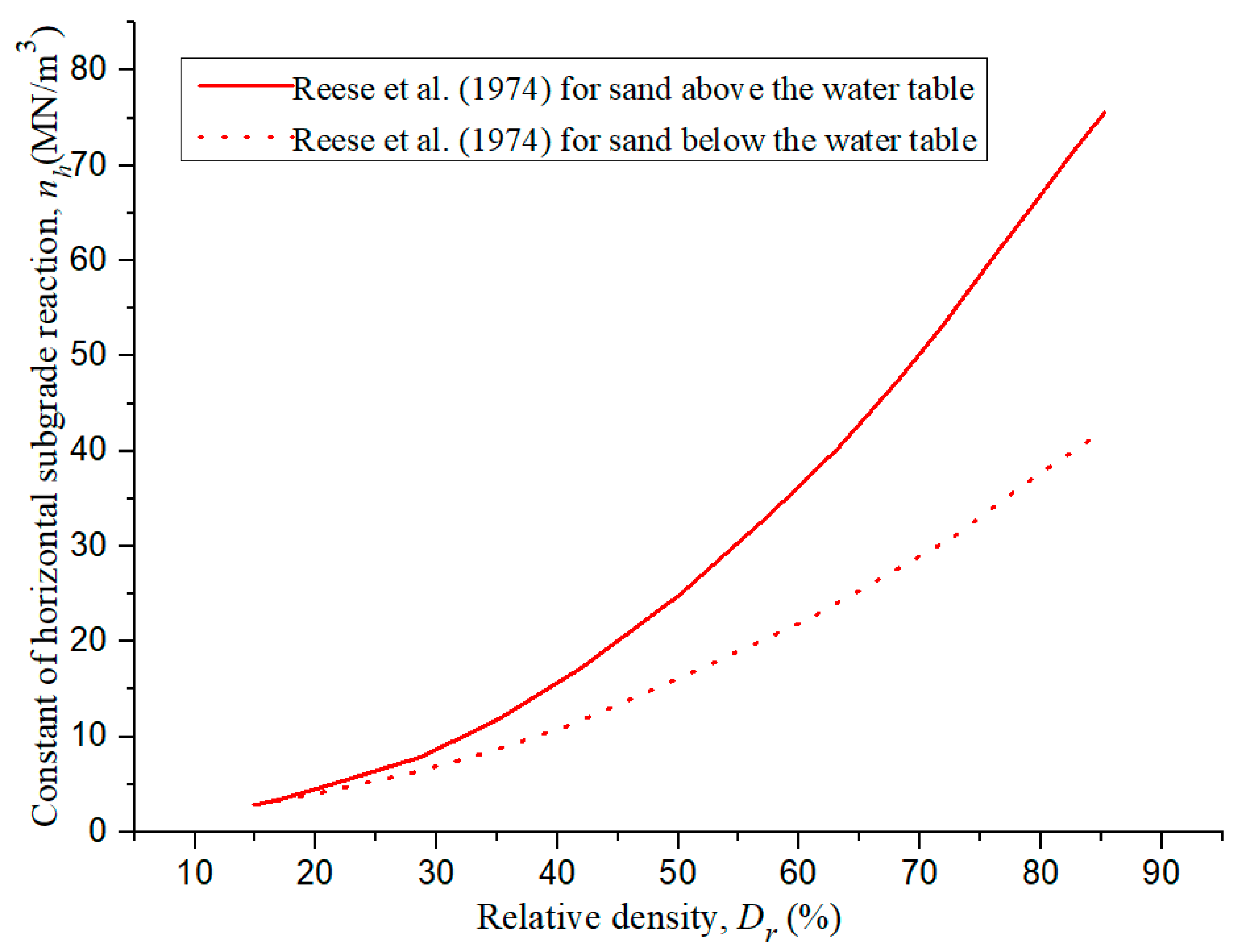
3.1. P-Y Curve Model

Laterally loaded piles are usually simplified as a series of continuous beam column elements, and nonlinear springs (i.e., p y curves) are used at the element nodes to describe the action of soil around piles. According to the Euler–Bernoulli beam theory, the basic differential equation can be expressed as
E I d 4 y d z 4 + p = 0
where y is the lateral deflection of pile; p is the soil reaction; E I is the bending stiffness of pile.
The soil reaction per unit depth p can be described by hyperbolic p y curve model and expressed as
p = y 1 k h + y p u
where k h is the horizontal subgrade reaction modulus and can reasonably be assumed to vary linearly with depth z [19]. Therefore, k h is expressed as
k h = n h z
where n h is the constant of horizontal subgrade reaction; its value is closely related to the relative density of cohesionless soil D r , and the value of n h can be determined as shown in Figure 6 [20].

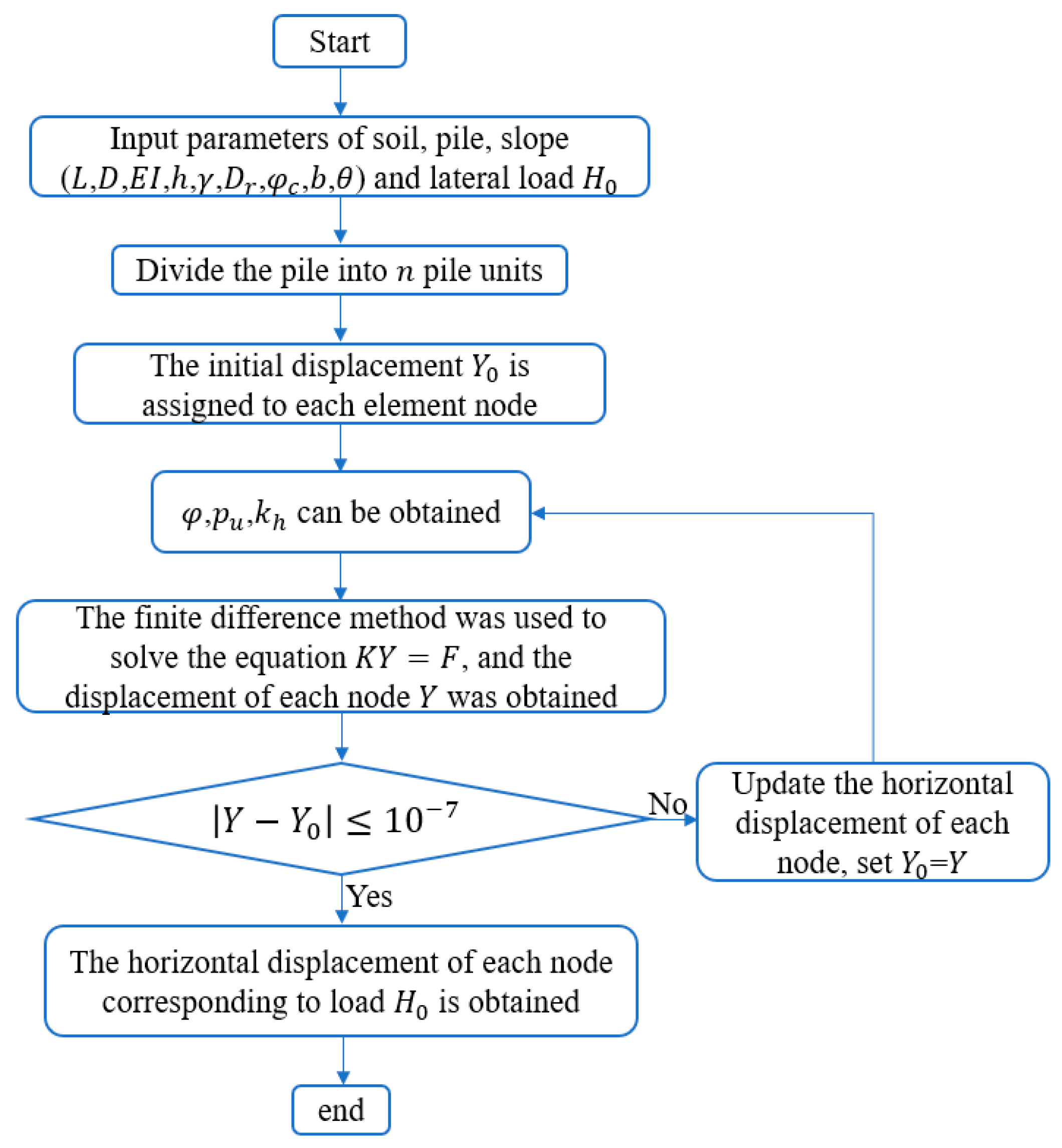
3.2. The Solution Flow Chart of the Proposed Method
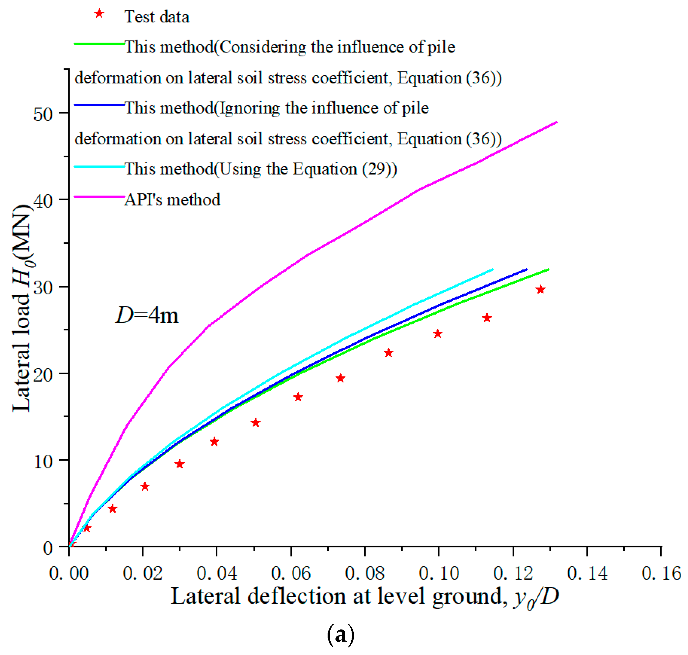
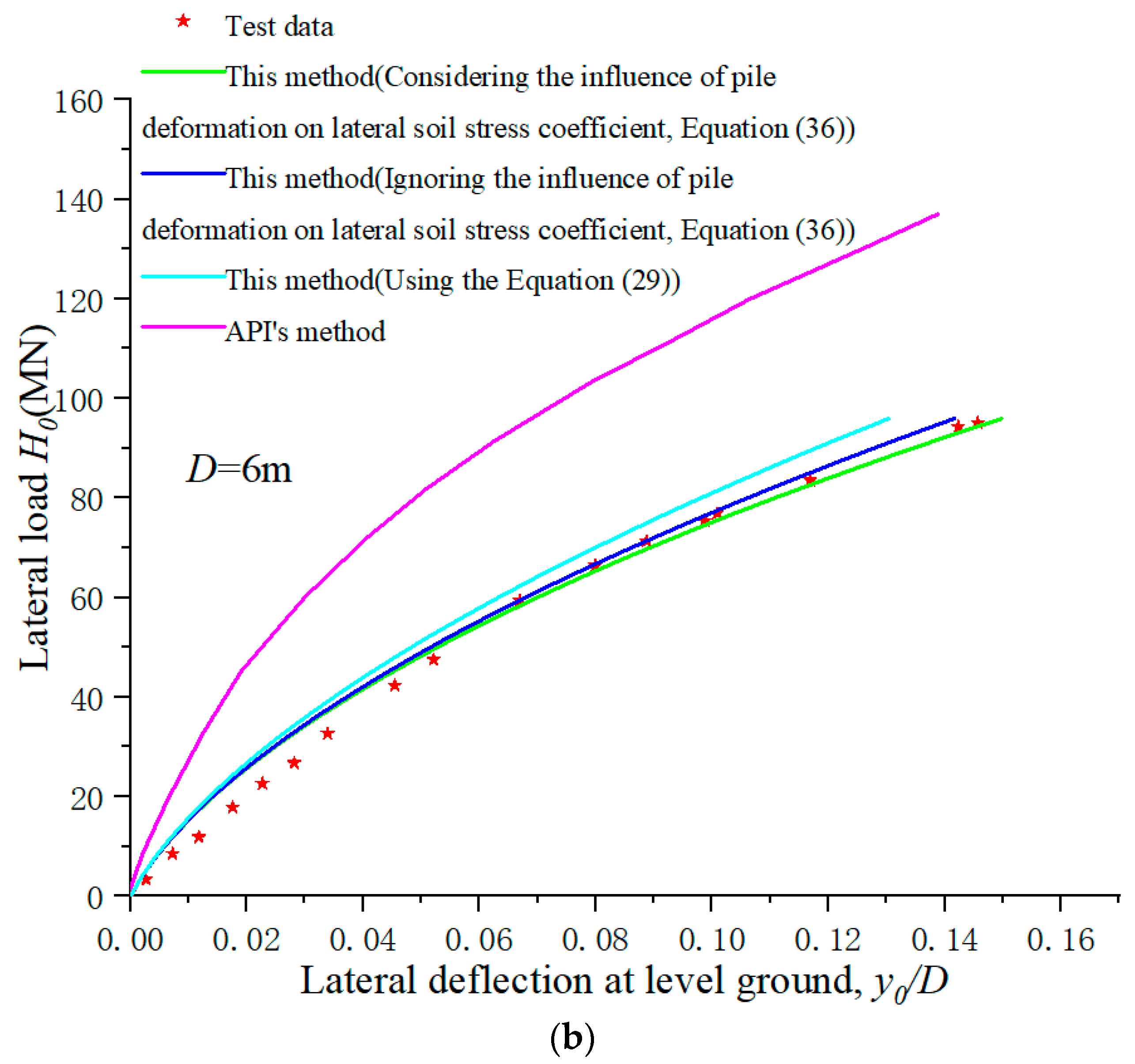
In this paper, the finite difference method is used to solve the lateral response of the pile near cohesionless slope under reverse lateral load. The solution principle and process are shown in Figure 7.

4. Validation

4.1. Centrifuge Test Pile

In order to study the lateral mechanism of large-diameter slender piles under lateral load, Wang et al. [21] carried out a series of centrifugal tests in the geotechnical centrifuge facility of Hong Kong University of Science and Technology. The model piles in this test are 7075-T6 aluminum alloy pipes with a length of 750 mm. The wall thickness of each model pile is 2 mm, the elastic modulus is 71.7 Gpa, and the Poisson’s ratio is 0.33. The outer diameter D of the two model piles is 40 mm and 60 mm, respectively. The two model piles were used to simulate the prototype piles with diameter D of 4 m and 6 m and flexure stiffness E I of 311   GN   ·   m 2 and 1106   GN   ·   m 2 , respectively. Moreover, the embedded depth L of the prototype pile is 60 m, and the acting height ( h ) of the lateral load is 10 m from the level ground. The used test sand is medium dense Toyoura sand. The minimum void ratio e m i n and maximum void ratio e m a x are 0.597 and 0.977, respectively. Its critical-state frictional angle φ c is 31°. The effective unit weight γ is 15.3 kN/m3, the relative density D r = 65%. So, the value of n h is 42 MN/m3. The results of the load-lateral deflection curve of the centrifugal experiment and the results of the calculation method in this paper are shown in Figure 8.
As shown in Figure 8, the predicted results of this method can well match the test results, while the calculated results of the API [22] method are quite different from the test results. The lateral bearing capacity of piles with D = 4 m and 6 m calculated by API [22] method overestimated by 69% and 52%, respectively, when based on y 0   = 0.1 D . Equation (29) is used to calculate the internal friction angle φ related to the peak mean effective stress p f . In this paper, the lateral bearing capacity of piles with D   = 4 m and 6 m calculated by Equation (29) is overestimated by 16% and 5.2%, respectively. Equation (36) is used to calculate the internal friction angle φ related to both the initial mean effective stress   p 0 and the lateral deflection of pile y . The lateral bearing capacity of piles with D = 4 m and 6 m calculated by Equation (36) with ignoring the influence of y (i.e., y = 0 ) is overestimated by 12% and 2.6%, respectively. The lateral bearing capacity of piles with D   = 4 m and 6 m calculated by Equation (36) with considering the influence of y is overestimated by 12% and 1.3%, respectively. Therefore, in the design of pile foundation engineering, the influence of the initial mean effective stress on the internal friction angle of sand should be considered, and the change of the stress state of sand caused by the lateral deflection of piles should be also considered.

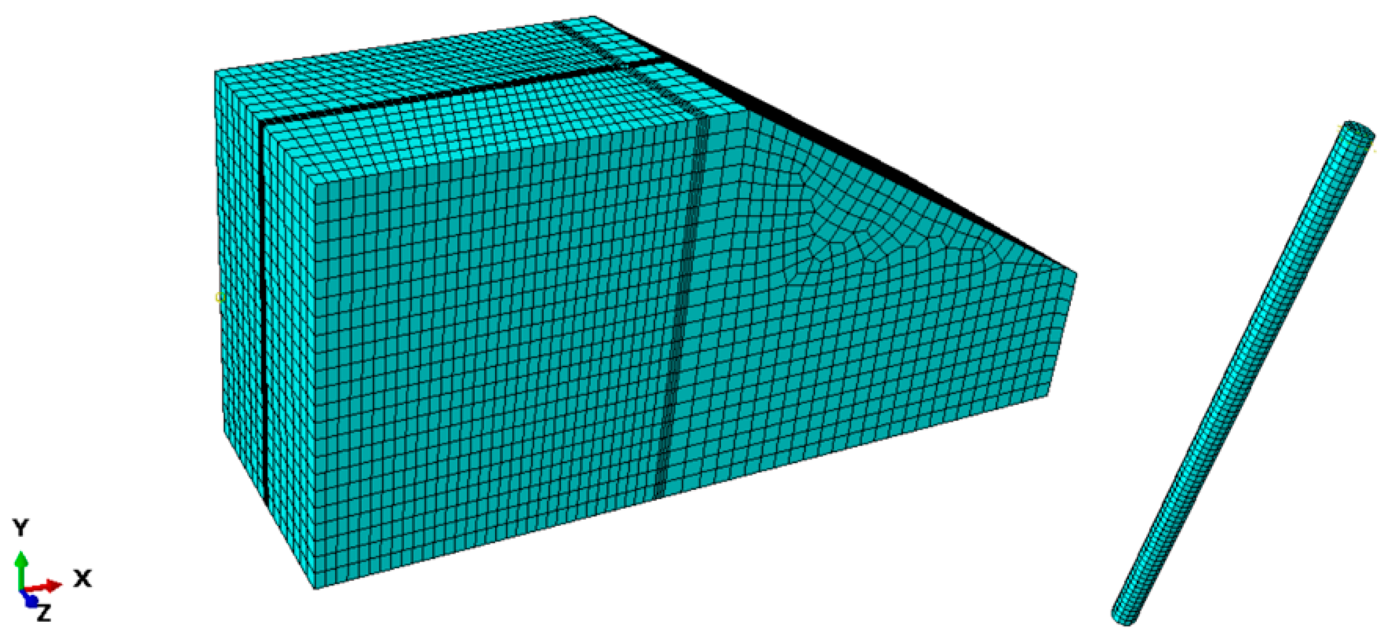
4.2. 3D FE Test Pile

Three-dimensional FE method is a commonly used method to analyze the bearing capacity of laterally loaded piles installed in level ground or near slope, and the rationality of this method has been verified [6,23]. Therefore, a 3D finite element model was established by using ABAQUS software in this paper to verify the accuracy of proposed method.
In the finite element model, it is assumed that pile is a linear elastic material and soil is an elastoplastic material that conforms to Mohr–Coulomb failure criteria [6]. The bottom of soil model is completely fixed, and the displacement of four side surfaces is limited by the radial displacement constraint criterion. The overall width and length of the model are greater than 10 times pile diameter D , and the distance from the bottom of the pile to the bottom of the model is greater than 10 D , so as to avoid the influence of boundary effect on the simulation results. The interaction between pile and soil is described by the Mohr–Coulomb friction law. The friction coefficient between soil and pile is μ = t a n 2 3 φ . C3D8 is used as the grid element type for both pile and soil. The comparison between the 3D FE analysis results established in this paper and the field test results conducted by Reese et al. [13] is shown in Figure 9. The good agreement between the two indicates the accuracy of the modeling method. The pile and soil parameters of the finite element model are shown in Table 1. The acting high h of H 0 is 0.3 m. The water table is at the level ground. The elastic modulus is calculated according to the flexural stiffness equivalence principle.
On this basis, the analytical model of pile foundation installed near slope under reversed lateral load is established in this paper [see Figure 10]. The slope angle is 30°. The pile diameter D is 1 m, and the distance from pile center to slope top is b = 4 D . The other parameters are still as shown in Table 1.
Figure 11 shows the load-deflection curve calculated by this method and the load-displacement curve results of three-dimensional FE analysis. It is reported that the critical-state frictional angle of sand at Mustang Island φ c is 28.5° [24], so this critical-state frictional angle value is adopted in the calculation of this method. The relative density D r of dense sand is 90%, so the value of n h is 43 MN/m3. As can be seen from Figure 11, the prediction results of the proposed method are in good agreement with the FE results, which indicates the rationality of the proposed method. In addition, by considering the influence of both the lateral deflection of pile y and the initial mean effective stress p 0 on the internal friction angle φ , the predicted results of the proposed method are closer to the FE analysis results. It can be seen that the initial mean effective stress and the change of sand stress state caused by pile displacement are important influences on the sand internal friction angle, and this effect needs to be taken into account in pile foundation design.

5. Discussion

5.1. Mean Effective Stress-Internal Friction Angle State of Sand

The internal frictional angle of sand is related to the initial mean effective stress p 0 and relative density D r . In the design of pile foundation, the pile will have lateral deflection under H 0 , so the stress state of sand around the pile will be affected by the lateral deflection of pile. Therefore, this section will explore the influence of different lateral deflection y generated by pile under different loads H 0 on the stress state and internal frictional angle of sand around the pile. At the same time, the influence of important index (i.e., relative density D r ) on the internal frictional angle of sand will also be analyzed. And the pile parameters and soil parameters used in this section are shown in Table 2.

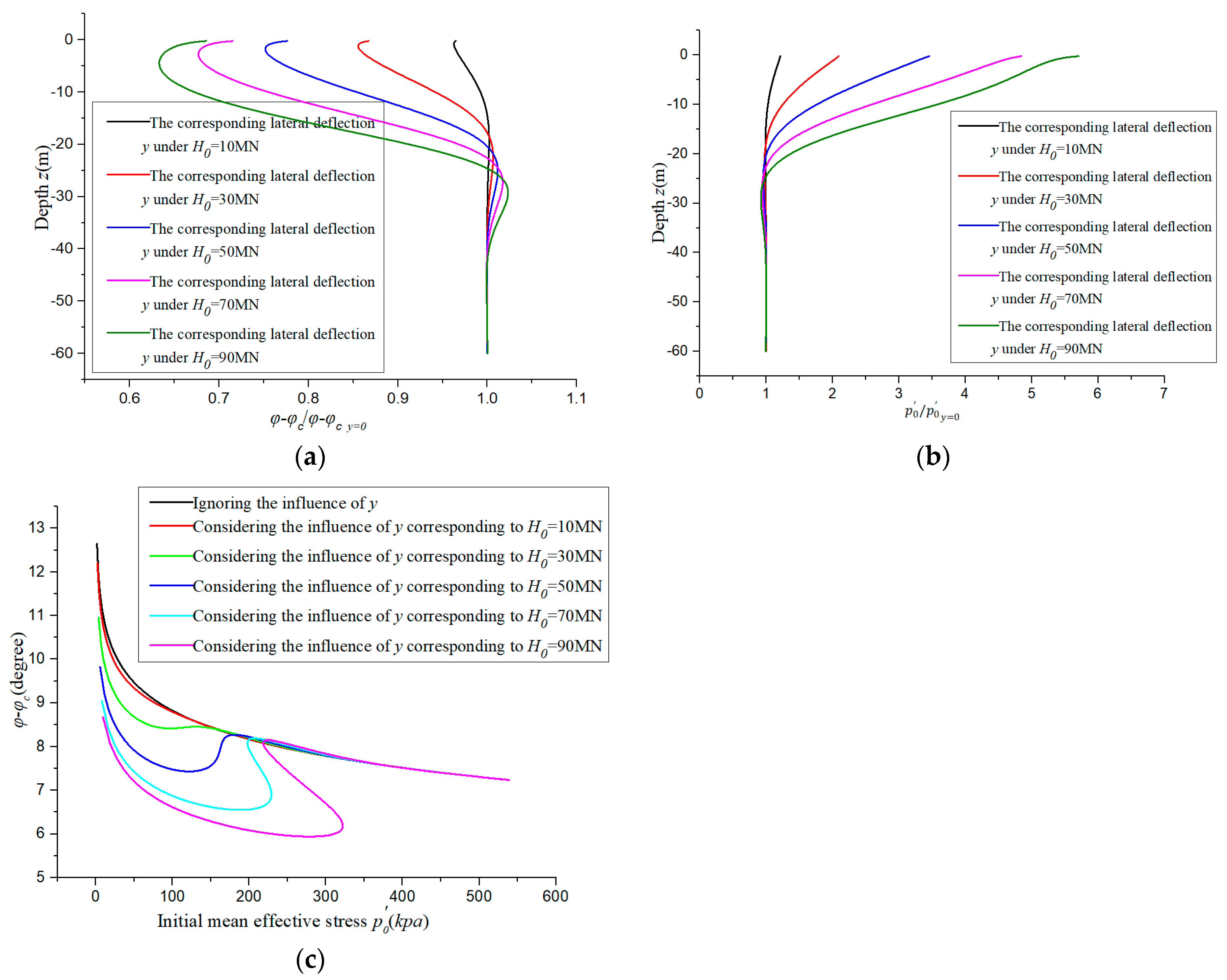
5.1.1. Correlation between y and Mean Effective Stress-Internal Frictional Angle State of Sand

Under the action of different H 0 , the lateral deflection y at the same depth will be different. In order to analyze the effect of lateral deflection y on the stress state and φ , this paper analyzes the relationship between the corresponding lateral deflection y on the stress state and internal frictional angle of sand when H 0 = 10   MN , 30   MN , 50   MN , 70   MN , and 90   MN , respectively. Figure 12a shows the ratio of φ φ c considering the effect of lateral deflection y to φ φ c   y = 0 and ignoring the effect of y at every depth. Figure 12b shows the ratio of p 0 considering the effect of lateral deflection y to p 0   y = 0 and ignoring the effect of y at every depth. Figure 12c shows the functional relationship between φ φ c and the initial mean effective stress p 0 under the influence of different lateral deflection y .
As can be seen from Figure 12a, at the shallow depth, φ φ c / φ φ c   y = 0 gradually decreases with the increase in lateral deflection, which indicates that the continuous lateral deflection of pile foundation will lead to changes in the state of sand around the pile, thus causing the decrease in the internal friction angle of the sand. At a depth of about 20–30 m (i.e., L /3~ L /2), φ φ c / φ φ c   y = 0 increases slightly with the increase in lateral deflection. However, the internal friction angle of sand in deeper depth is almost not affected by the lateral deflection y , which is the reason that the lateral deflection of the lower pile foundation is small. It can be seen from Figure 12b that p 0 / p 0   y = 0 increases with the increase in lateral deflection, indicating that the initial mean effective stress of sand around the pile increases during the lateral deflection of the pile, while the initial mean effective stress state changes little at the depths of more than 20 m. In Figure 12c, when ignoring the influence of lateral deflection y on sand state, the relationship between φ φ c and the initial mean effective stress p 0 is a monotonic decreasing function. When the lateral deflection y increases to a certain value, the relationship between the two will gradually change (namely, the decreasing–increasing–decreasing relationship), and the degree of this effect will be more significant with the increase in y .

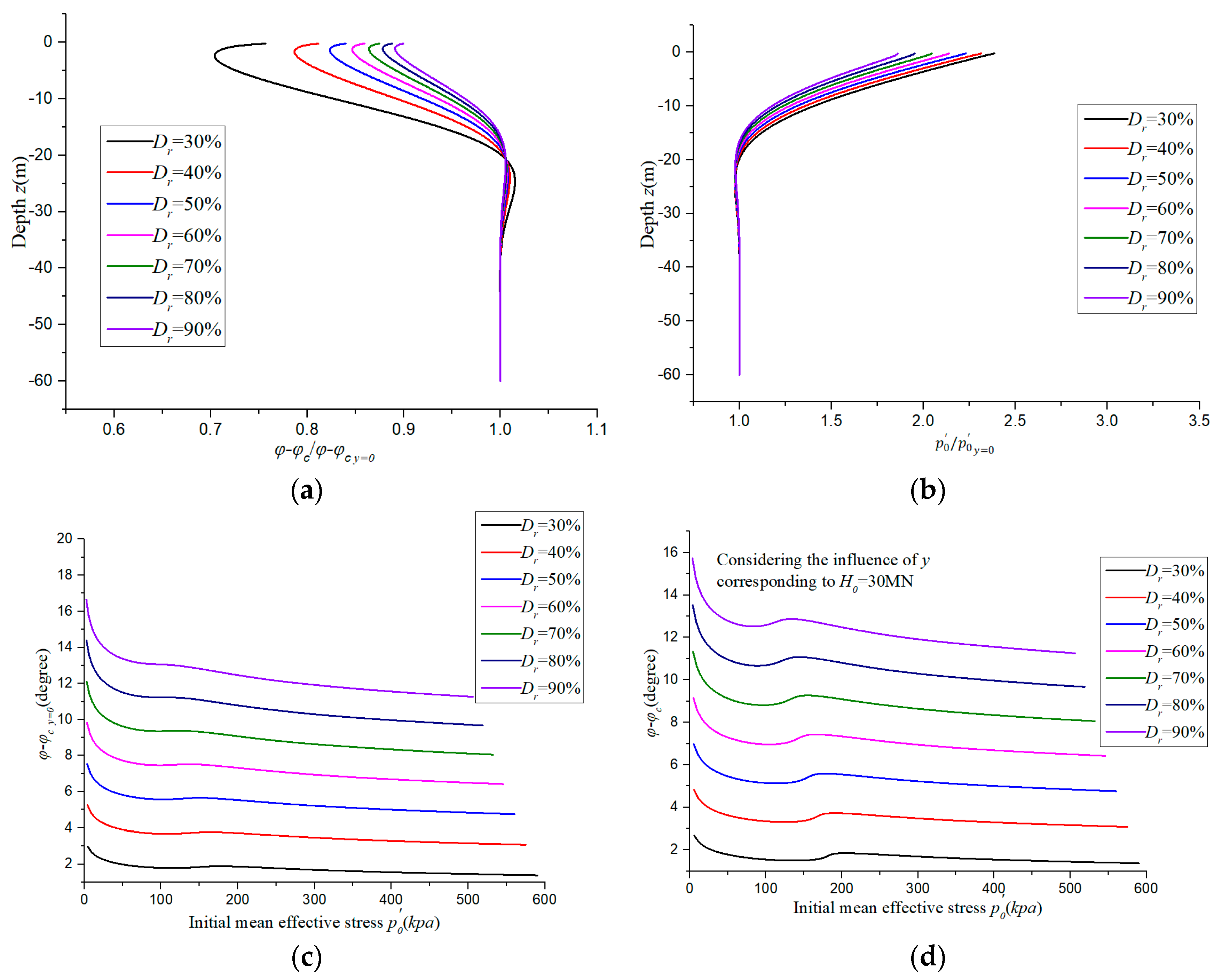
5.1.2. Correlation between Relative Density D r and Mean Effective Stress-Internal Friction Angle State of Sand

This section will discuss the influence of D r of sand on the initial mean effective stress and internal frictional angle of sand and consider the effect of y corresponding to H 0 = 30   M N on the sand state. Figure 13a,b, separately shows the ratio of φ φ c / φ φ c   y = 0 and p 0 / p 0   y = 0 at every depth. It is worth noting that φ φ c / φ φ c   y = 0 at each depth increases with the increase in D r , while p 0 / p 0   y = 0 at each depth decreases with the increase in D r . As shown in Figure 13c,d, the curve value of the relationship between φ φ c and p 0 increases with the increase in D r . Therefore, it can be seen that D r has great influence on the internal friction angle and stress state level of sand.

5.2. Pile Lateral Characteristic

Figure 14 shows the results of the influence of sand state considering lateral deflection y on the lateral characteristics of pile when H 0 = 90   MN and 110   MN . In Figure 14a, the bending moment calculated by the case considering the influence of lateral deflection y on the sand is greater than that calculated by ignoring the influence of lateral deflection y on the sand. When H 0 = 110   M N , the maximum bending moment M m a x calculated by the case considering the influence of lateral deflection y on the sand is 4.6% higher than that calculated for ignoring the influence of y . At the same time, as shown in Figure 14b, it is worth noting that the pile deflection calculated by the case considering the influence of lateral deflection y on the sand is also larger than that calculated by ignoring the influence of lateral deflection y . This shows that the lateral deflection process of pile changes the original stress state of the soil, which reduces the resistance of the soil around the pile. Therefore, in the design of piles, the influence of the change of soil around the pile caused by the lateral deflection of the pile should be considered, so as to reasonably evaluate the resistance of soil for accurate design.

6. Conclusions

In this study, a new p y curve analysis method for piles near cohesionless slope under reversed lateral load is proposed. The relationship between internal friction angle of sand and all of D r , the initial mean effective stress, and the change in the stress state of the soil around the pile caused by the lateral deflection of the pile foundation is considered, so as to accurately evaluate the internal frictional angle of the sand at each depth. In addition, the ultimate soil resistance of a pile near cohesionless slope under reverse loading is deduced based on the failure mode of soil around pile and the interaction between pile and soil. The obtained internal friction angle is substituted into the calculation of ultimate soil resistance to obtain its accurate value. Good comparisons are achieved between the results of this method and both FE analysis results and published pile test data. In addition, the following conclusions can be drawn:
(1) Compared with the test results of case history, the bearing capacity of pile foundation D   = 4 m and 6 m calculated by the method in this paper is overestimated by 16% and 5.2%, respectively, when considering the mean effective stress under the peak shear strength. When considering the influence of the initial mean effective stress ( p 0 ) and lateral deflection of pile ( y ), the results are only overestimated by 12% and 1.3%, respectively.
(2) In the process of lateral deflection of a pile, the state of surrounding soil will be changed. The internal frictional angle of cohesionless soil will decrease gradually in this process when the depth is between 0 and L / 3 , and increase gradually when the depth is between L / 3 and L / 2 , while the internal frictional angle of the soil at the lower depth changes little.
(3) The internal friction angle at each depth increases with the relative density of sand, while the stress level at each depth decreases with the increase in relative density.
(4) During the lateral deflection of the pile, the original stress state of the soil is changed so that the resistance of the soil around pile is reduced. When H 0 = 110   MN , M m a x is calculated by the case, considering that the influence of y on the sand is 4.6% higher than that calculated for ignoring the influence of y .

Author Contributions

C.J.: Resources, Formal analysis. J.L.: Methodology, Validation, Supervision. M.L.: Methodology, Writing—review and editing, Software. All authors have read and agreed to the published version of the manuscript.

Funding

This research was funded by National Natural Science Foundation of China grant number 51978665.

Institutional Review Board Statement

Not applicable.

Informed Consent Statement

Not applicable.

Data Availability Statement

The datasets generated during the current study are available from the corresponding author on reasonable request.

Conflicts of Interest

The authors declare no conflict of interest.

References

  1. Wang, H.; Wang, L.Z.; Hong, Y.; Askarinejad, A.; He, B.; Pan, H.L. Influence of Pile Diameter and Aspect Ratio on the Lateral Response of Monopiles in Sand with Different Relative Densities. J. Mar. Sci. Eng. 2021, 9, 618. [Google Scholar] [CrossRef]
  2. He, B.; Lai, Y.Q.; Wang, L.Z.; Hong, Y.; Zhu, R.H. Scour Effects on the Lateral Behavior of a Large-Diameter Monopile in Soft Clay: Role of Stress History. J. Mar. Sci. Eng. 2019, 7, 170. [Google Scholar] [CrossRef] [Green Version]
  3. Liang, F.Y.; Zheng, H.B.; Zhang, H. On the pile tension capacity of scoured tripod foundation supporting offshore wind turbines. Appl. Ocean. Res. 2020, 102, 102323. [Google Scholar] [CrossRef]
  4. Mezazigh, S.; Levacher, D. Laterally loaded piles in sand: Slope effect on P-Y reaction curves. Can. Geotech. J. 1998, 35, 433–441. [Google Scholar] [CrossRef]
  5. Georgiadis, K.; Georgiadis, M. Development of p-y curves for undrained response of piles near slopes. Comput. Geotech. 2012, 40, 53–61. [Google Scholar] [CrossRef]
  6. Chae, K.S.; Ugai, K.; Wakai, A. Lateral resistance of short single piles and pile groups located near slopes. Int. J. Geomech. 2004, 4, 93–103. [Google Scholar] [CrossRef]
  7. Lin, M.K.; Jiang, C.; Chen, Z.; Liu, P.; Pang, L. A method for calculating lateral response of offshore rigid monopile in sand under slope effect. Ocean. Eng. 2022, 259, 111812. [Google Scholar] [CrossRef]
  8. Broms, B.B. Lateral resistance of piles in cohesive soils. J. Soil Mech. Found. Div. 1964, 90, 27–64. [Google Scholar] [CrossRef]
  9. Hansen, J.B. The Ultimate Resistance of Rigid Piles against Transversal Forces; Bulletin 12; Danish Geotechnical Institute: Copenhagen, Denmark, 1961; pp. 5–9. [Google Scholar]
  10. Bolton, M.D. The strength and dilatancy of sands. Geotechnique 1986, 36, 65–78. [Google Scholar] [CrossRef] [Green Version]
  11. Chakraborty, T.; Salgado, R. Dilatancy and shear strength of sand at low confining pressures. J. Geotech. Geoenvironmental Eng. 2010, 136, 527–532. [Google Scholar] [CrossRef]
  12. Yang, J.; Mu, F. Use of state-dependent strength in estimating end bearing capacity of piles in sand. J. Geotech. Geoenvironmental Eng. 2008, 134, 1010–1014. [Google Scholar] [CrossRef]
  13. Reese, L.C.; Cox, W.R.; Koop, F.D. Analysis of laterally loaded piles in sand. In Proceedings of the 6th Annual Offshore Technology Conference, Houston, TX, USA, 6–8 May 1974. [Google Scholar]
  14. Kim, Y.; Jeong, S.; Lee, S. Wedge failure analysis of soil resistance on laterally loaded piles in clay. J. Geotech. Geoenvironmental Eng. 2011, 137, 678–694. [Google Scholar] [CrossRef]
  15. Bowman, E.R. Investigation of the Lateral Resistance to Movement of a Plate in Cohesionless Soil. Master’s Thesis, University of Texas at Austin, Austin, TX, USA, 1958. [Google Scholar]
  16. Kulhawy, F.H. Drilled shaft foundations. In Foundation Engineering Handbook, 2nd ed.; Fang, H.-Y., Ed.; Springer: Van Nostrand Reinhold, NY, USA, 1991; Chapter 14. [Google Scholar]
  17. Mei, G.X.; Zai, J.M. Rankine earth pressure model considering deformation. J. Rock Mech. Eng. 2001, 20, 851–854. [Google Scholar]
  18. Zhang, X.L.; Xue, J.Y.; Xu, C.S.; Liu, K.Y. An analysis method for lateral capacity of pile foundation under existing vertical loads. Soil Dyn. Earthq. Eng. 2021, 142, 106547. [Google Scholar] [CrossRef]
  19. Terzaghi, K. Evaluation of coefficient of subgrade reaction. Geotechnique 1955, 5, 297–326. [Google Scholar] [CrossRef]
  20. Zhang, L.Y. Nonlinear analysis of laterally loaded rigid piles in cohesive soil. Comput. Geotech. 2009, 36, 718–724. [Google Scholar] [CrossRef]
  21. Wang, H.; Wang, L.Z.; Hong, Y.; Mašín, D.; Li, W.; He, B.; Pan, H.L. Centrifuge testing on monotonic and cyclic lateral behavior of large-diameter slender piles in sand. Ocean. Eng. 2021, 226, 108299. [Google Scholar] [CrossRef]
  22. API American Petroleum Institute. Geotechnical and Foundation Design Considerations; API RP 2GEO; API: Washington, DC, USA, 2011. [Google Scholar]
  23. Peng, W.Z.; Zhao, M.H.; Xiao, Y.; Yang, C.H.; Zhao, H. Analysis of laterally loaded piles in sloping ground using a modified strain wedge model. Comput. Geotech. 2019, 107, 163–175. [Google Scholar] [CrossRef]
  24. Lin, C.; Bennett, C.; Han, J.; Parsons, R.L. Scour effects on the response of laterally loaded piles considering stress history of sand. Comput. Geotech. 2010, 37, 1008–1014. [Google Scholar] [CrossRef]
Figure 1. The direction of the lateral load acting on the pile foundation: (a) forward loading; (b) reverse loading.
Jmse 11 00741 g001
Figure 2. Passive wedge and active wedge formed in front of and behind the pile under lateral load: (a) The active wedge does not develop to the slope; (b) The active wedge has developed to the slope.
Jmse 11 00741 g002
Figure 3. Post-pile active wedge failure mode above critical depth z c and the system of forces.
Jmse 11 00741 g003
Figure 4. Post-pile active wedge failure mode below critical depth z c and the system of forces.
Jmse 11 00741 g004
Figure 5. Three-dimensional diagram of passive wedge in front of the pile.
Jmse 11 00741 g005
Figure 6. The relation between n h and D r [13].
Jmse 11 00741 g006
Figure 7. The solution flow chart of the proposed method.
Jmse 11 00741 g007
Figure 8. Comparison with load-deflection test results at level ground: (a) D = 4 m; (b) D = 6 m.
Jmse 11 00741 g008aJmse 11 00741 g008b
Figure 9. Validation of 3D finite element modeling method.
Jmse 11 00741 g009
Figure 10. Three-dimensional finite element mesh.
Jmse 11 00741 g010
Figure 11. Comparison with load-deflection test results of 3D FE model.
Jmse 11 00741 g011
Figure 12. The influence of lateral deflection y of pile on mean effective stress-internal friction angle state of sand: (a) φ φ c / φ φ c y   = 0 at different depths; (b) p 0 / p 0 y   = 0 at different depths; (c) The relationship between φ φ c and p 0 .
Jmse 11 00741 g012
Figure 13. The influence of relative density D r on mean effective stress-internal friction angle state of sand: (a) φ φ c / φ φ c y   = 0 at different depths; (b) p 0 / p 0 y   = 0 at different depths; (c) The relationship between φ φ c and p 0 (ignoring the influence of y ); (d) The relationship between φ φ c and p 0 (considering the influence of y ).
Jmse 11 00741 g013
Figure 14. Influence of the sand state considering lateral deflection y on the pile lateral characteristic: (a) Curve of bending moment of pile versus depth; (b) Curve of lateral deflection of pile versus depth.
Jmse 11 00741 g014
Table 1. Soil and pile parameters in 3D FE model.
E   p a υ γ   k N / m 3 c   k P a φ ψ L   m D   m
Pile 2.52 × 10 10 0.368///210.61
Soil 1.65 × 10 7 0.390.2399//
Table 2. Soil and pile parameters in this section.
E   p a L   m γ   k N / m 3 D   m φ c b θ h   (m) D r
Pile 2.52 × 10 10 21/1/ 0.3
Soil / /9/28.5° b = 4 D 30°/90%
Note: E is elastic modulus of the pile; L is embedded depth; γ is the unit weight of sand; D is pile diameter; φ c is critical-state friction angle; b is the distance from pile center to slope top; θ is slope angle; h is the height from the point where the lateral load acting on pile to the horizontal ground; D r is relative density.
Disclaimer/Publisher’s Note: The statements, opinions and data contained in all publications are solely those of the individual author(s) and contributor(s) and not of MDPI and/or the editor(s). MDPI and/or the editor(s) disclaim responsibility for any injury to people or property resulting from any ideas, methods, instructions or products referred to in the content.

