
On the Resistance of Cruciform Structures during Ship Collision and Grounding

School of Naval Architecture and Ocean Engineering, Jiangsu University of Science and Technology, Zhenjiang 212003, China
*
Author to whom correspondence should be addressed.
J. Mar. Sci. Eng. 2023, 11(2), 459; https://doi.org/10.3390/jmse11020459
Submission received: 29 December 2022
/
Revised: 1 February 2023
/
Accepted: 15 February 2023
/
Published: 20 February 2023
(This article belongs to the Special Issue Advanced Analysis of Marine Structures)
Abstract
:This paper presents an experimental, numerical, and analytical study of a novel specimen subjected to local in-plane load, to investigate its crushing deformation and resistance. The specimen was designed and fabricated to simplify the cruciform structure in double-hulled vessels subjected to external loads during collision and grounding incidents. The study results will provide reliable insights into grounding scenarios as well as side collision scenarios of double-hulled vessels. A quasi-static indentation test and related numerical research showed good agreement regarding deformation mode and force–displacement response. On the basis of the experimental and numerical results, an analytical method is proposed to derive the deformation energy, the instantaneous resistance, and the mean resistance of the deformed structure. The analytical method was verified with recorded test data and a nonlinear finite element analysis. It enables a rapid assessment of the response of the structure under accidental loads, which is a guideline for the design of crashworthy hull structures and the assessment of their crashworthiness.
1. Introduction
Ship collision and grounding accidents may cause catastrophic consequences such as casualties, economic losses, and environmental pollution [1]. According to the statistics of the International Oil Tanker Owners Oil Pollution Federation (ITOPF), 62% of large spills (over 700 tonnes) recorded between 1970 and 2021 were caused by collisions and groundings [2]. In order to reduce losses caused by impact accidents, it is essential to develop procedures to assess double-hull tanker performance in collision and stranding accidents.
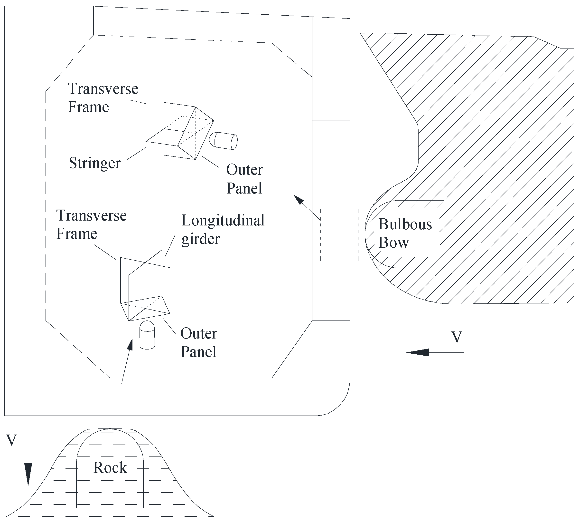
Cruciform structures in double hulls consist of joints between side stringers and transverse webs in a double side, as well as longitudinal girders and transverse frames in a double bottom. Figure 1 shows a typical collision and grounding scenario for a double-hull vessel: the bulbous bow of the collision ship and rock are simplified into rigid hemispheroid, and cruciform structures connected with outer panels suffer local axial compression load in the schematic. During the ship collision and grounding, the cruciform structure acts as one of the main structures resisting the deformation and absorbing the impact energy. Therefore, it is essential to investigate the deformation mechanism, energy absorption, and resistance of cruciform structures under in-plane loading.
In recent decades, a number of studies have been carried out focusing on the mechanical behavior of cruciforms, including model tests, numerical simulations, and simplified analytical methods. The experimental method has all along been the most reliable research means to assess the crashworthiness of hull structures. The test results provide initial insights and reliable data. Urban et al. [3] conducted crush experiments on full-size aluminum cruciform structures and the results indicated that the material fracture generated during deformation had a significant effect on its crushing behavior. Dramatic reductions were found in the energy dissipation of the specimen when fractures occurred. Abramowicz and Simonsen [4] carried out two series of crushing tests. In the first group, relatively thin steel specimens were used to investigate the relationship between structural energy absorption and the ratio of breadth to thickness (c/t). In the second group, the effect of absolute size on structural energy absorption was investigated by increasing the thickness of the plate while keeping c/t constant. The test results from Urban, as well as Abramowicz and Simonsen, became the benchmarks for later studies and provided reliable data. Zhou [5] carried out tests on three types of cruciform structures with different welding positions and lengths, and the results indicated that the energy absorption capacity of energy absorbers is tunable by adjusting the weld strength of components. Ghanbari Ghazijahani et al. [6] conducted tests to investigate the resistance and deformation mode of shell structures with different indentations.
With the rapid development of high-performance computers, numerical simulation analysis is widely used to investigate the structural response of ships subjected to collision or stranding. Mohammed et al. [7] carried out numerical simulations on the basis of Simonsen’s test results and the results were validated by comparison with experimental tests and DNV design code. However, material fracture and contact algorithms were not included in the simulation. Urban [8] conducted numerical simulation analyses and compared them with previous data. Various failure criteria were used in the simulation which, implemented with RTCL fracture criterion, agreed with experimental results. Haris et al. [9] also conducted numerical research based on Urban’s test with LS-DYNA to validate the numerical method. Subsequently, they defined the concept of the effective cruciform width and utilized it in the crushing simulation of ship girder intersections with realistic boundary conditions. Sun et al. [10] simulated the response of the side of double-hull tanker collided at the cruciform by a rigid bow, and the numerical results were compared with a simplified method based on the study of Haris [11]. The finite element method is becoming an indispensable tool in the study of ship structures.
Generally speaking, numerical simulation calculations often require extensive modeling efforts and incur computational costs. Therefore, the analytical method remains important in structural analysis to rapidly evaluate the crashworthiness of hull structures. The simplified analytical method for crushing modeling is based on a simplified energy method called the ‘kinematic method’; several scholars [12,13,14] have used it to investigate energy dissipation in crushed structures. Amdahl et al. [12] proposed the symmetric and asymmetric collapse modes of a cruciform structure and derived its mean crushing strength. Wierzbicki [15] studied the crushing resistance of structures consisting of different numbers of panels and proposed closed-form solutions for the mean crushing resistance of cruciforms and other basic structural elements. Hayduk and Wierzbicki [16] considered the collapse mode of cruciforms as an assembly folding mode of two basic plates, and two simplified combination fold modes were presented as upper and lower bounds of mean cruciform crushing strength. Kierkegaard et al. [17] derived a mathematical method for calculating force–indentation relations on the basis of axial crushing mechanisms for basic elements including L-, T-, and X-elements (cruciforms), and the calculated results were verified with crushing experiments of bow models provided in the previous literature [18]. Abramowicz [19] proposed formulae for calculating the axial resistance of these L-, T-, and X-shaped structures.
Table 1 lists previous research on the resistance of cruciforms. In these works, the structural responses of cruciforms subjected to flat indenters were widely studied, and the mechanical mechanisms under local indentation were less addressed. In fact, when the shape of the impacting bow or reef is more convex, the cruciform is subjected to a local compression load. This motivated us to investigate the crushing resistance and progressive deformation of cruciforms under local compress load experimentally, numerically, and analytically.
This paper investigates the mechanical response of cruciforms under local indentation loads. The specimen was designed and fabricated as a simplified structure of cruciform intersections in double sides or double bottoms. The analysis of the specimen was conducted via a quasi-static indentation test, nonlinear finite element simulations, and an analytical method. The details of the test and numerical simulation are provided herein, with good agreement between the recorded test data and the numerical results. In addition, a simplified analytical method was proposed to rapidly assess the instantaneous and mean crushing resistance of the cruciform structures in a double-hull structure in the event of a collision with a hemispherical object (for example, a seabed rock or a bulbous bow). The analysis was validated based on the force–displacement response of the test and the simulations, Which means that this newly proposed analytical method is an effective tool for the assessment of the crashworthiness of cruciforms in grounding or collision scenarios.
2. Experimental Details
2.1. Test Specimen
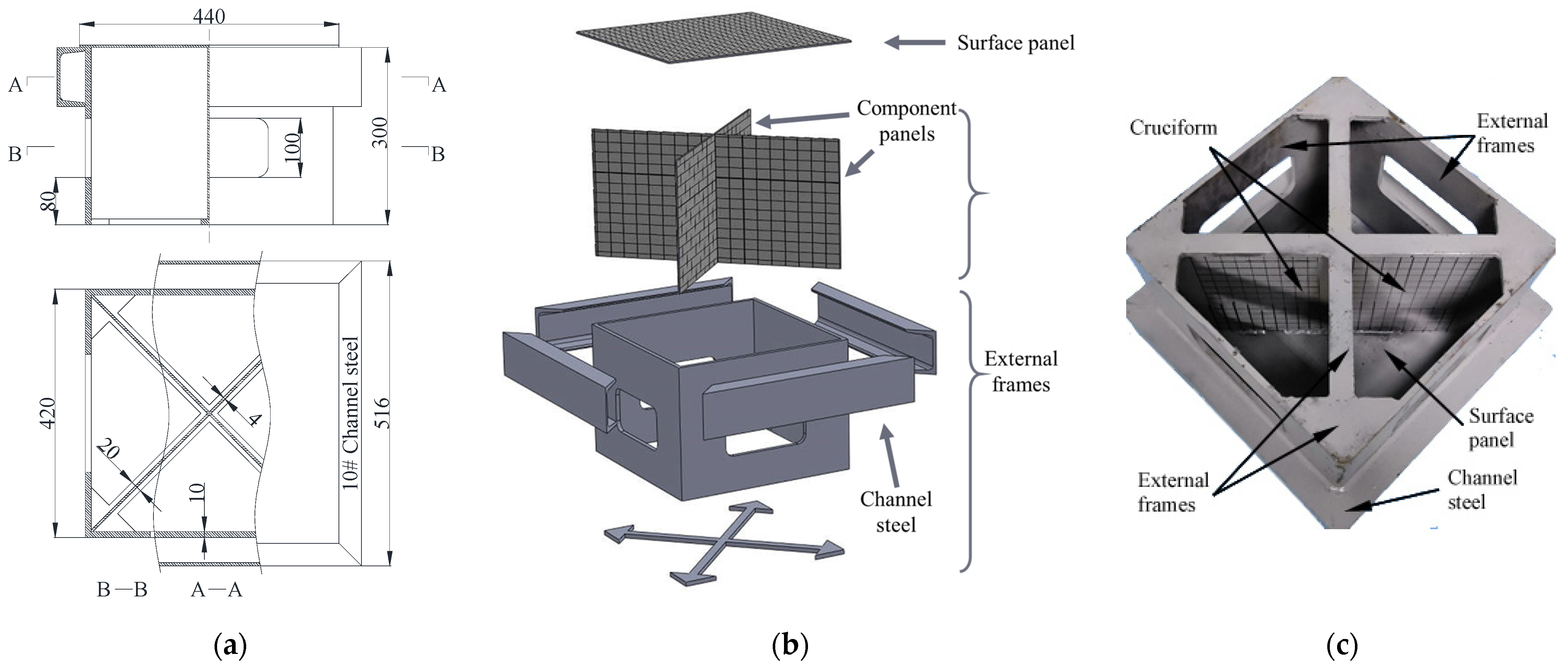
To investigate the crashworthiness of cruciform structures, a specimen was designed and manufactured. Figure 2 shows the schematic of the specimen consisting of a cruciform, a surface plate, and external frames. The specimen is simplified from a typical intersection structure on a double-hull vessel. Four 4 mm thick component panels were welded into the cruciform, and a 4 mm thick surface plate representing the outer hull panels was welded to the cruciform. The simplified hull structure was welded to the inside of a 10 mm thick support frame structure. The upper part of the external frame was reinforced with channel steels all around. The edges of the surface plate were joined to the channel steels with welded seams and the whole specimen was constructed from mild steel. The specimen was painted silver–grey and grids (20 × 20 mm) were drawn on the cruciform and surface panel so that the extent of the deformation of the specimen could be easily observed.
2.2. Quasi-Static Indentation Test
Since collisions and groundings of ships often occur at low speeds, as a simplified approach, quasi-static tests are applied to investigate the mechanical response of hull structures under impact [20,21]. In addition, quasi-static tests allow the continuous recording of test data during the damage process, which allows the proposal of simplified methods for the analysis of structural damage and deformation [22]. In order to investigate the deformation of the hull structure in collisions with a small rock or a bow, a hemispherical indenter with a radius of 75 mm was chosen for the test. The indenter was produced from hardened GCr15 that would not deform during loading.
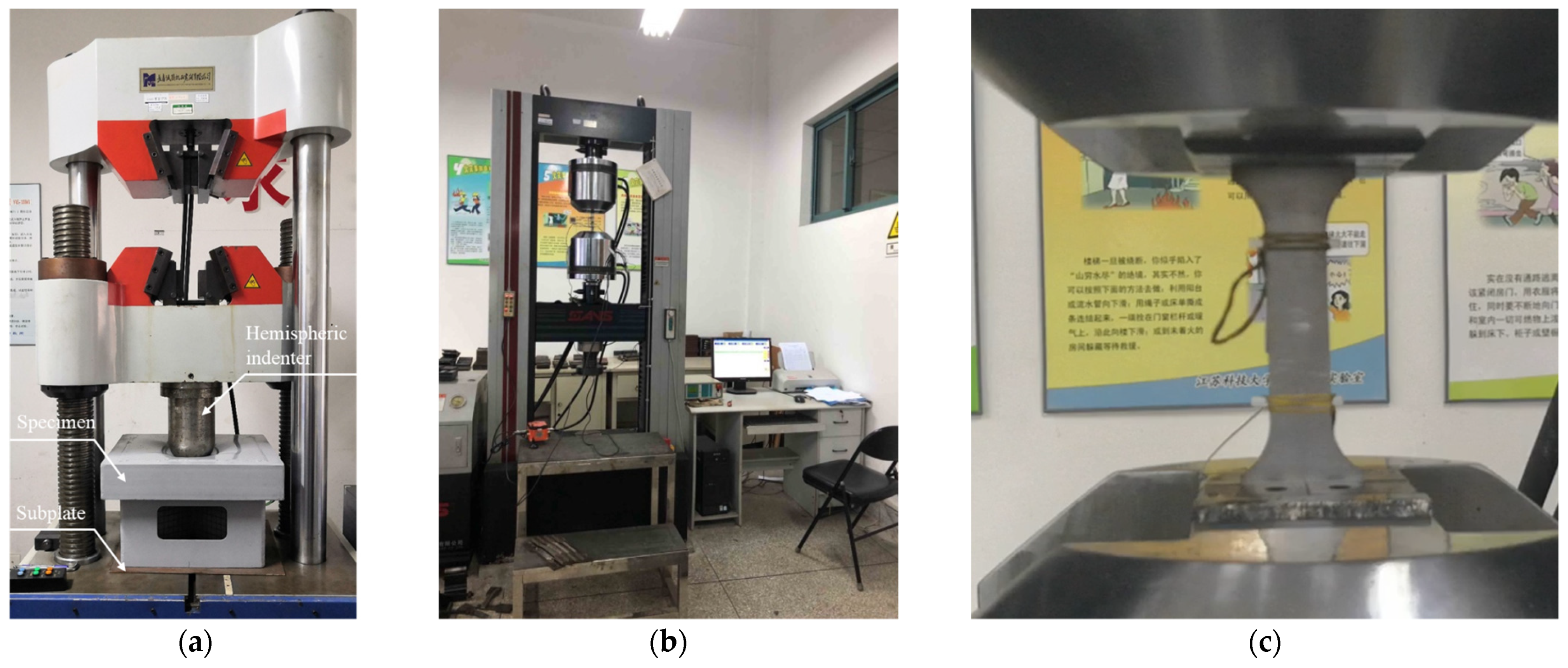
The test setup is presented in Figure 3a. The indentation was executed with an Electro-hydraulic servo universal testing machine (YNS1000, CRIMS, Changchun, China) with a 1000 kN maximum load. The central axis of the specimen should be aligned with the central axis of the indenter to ensure in-plane loading of the cruciform. Before the test, the indenter was lowered until it contacted the specimen, followed by clearing the load to zero. During the test, the indenter was forced down at a constant velocity of 10 mm/min to ensure the quasi-static loading condition. The displacement and load data were recorded using the testing machine with a sampling frequency of 20 Hz.
2.3. Tensile Test
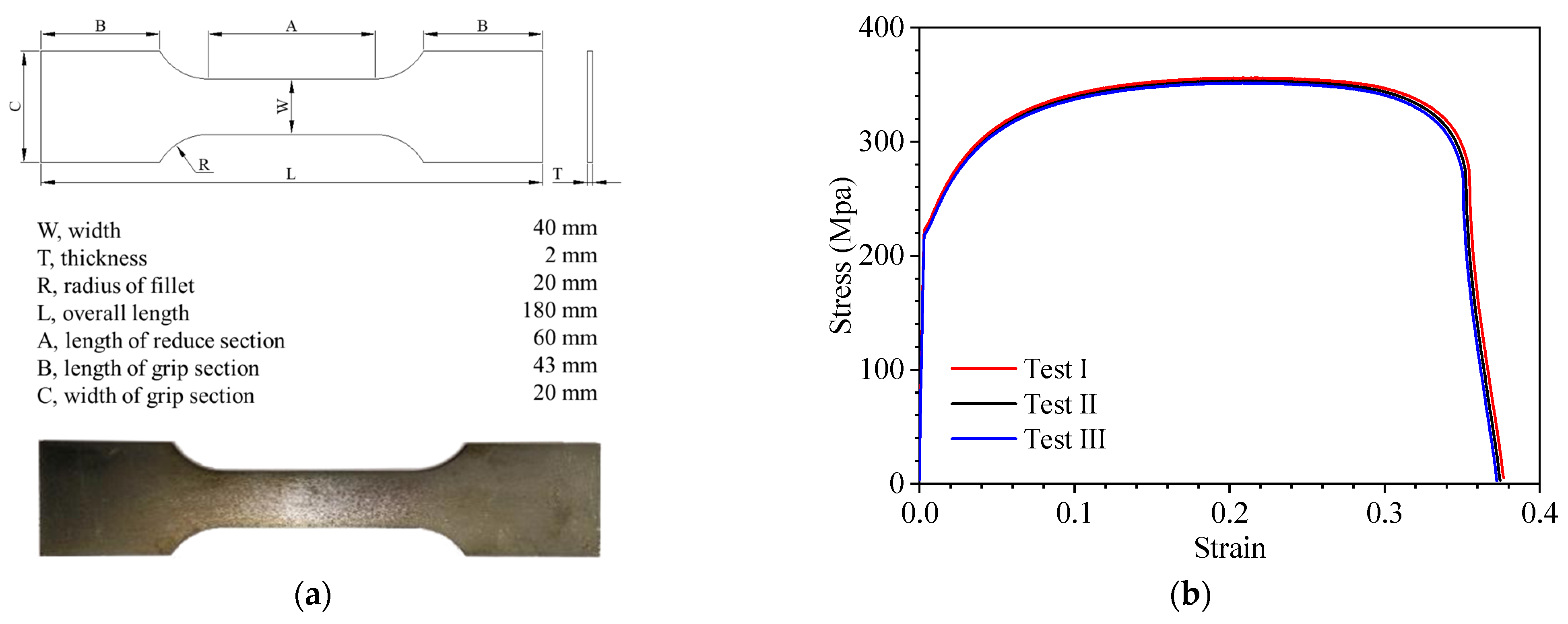
Before the indentation test, quasi-static tensile tests were performed to obtain the mechanical properties of the material. Tensile specimens were manufactured with the same material as the cruciform specimen. The tensile tests were carried out with a universal testing machine (CMT5305, MTS, Shanghai, China). The fabrication of the specimens and fulfilment of the tests were executed in accordance with standard protocols [23] and are shown in Figure 3b,c and Figure 4a. The specimen was stretched at a constant velocity of 1 mm/min. To reduce the effects of errors, the tests were carried out three times. The elongation and load were recorded with an extensometer and a force transducer, respectively, during the test. The engineering curves are plotted in Figure 4b and satisfactory repeatability is observed. The mechanical properties of the mild steel listed in Table 2 are extracted from the engineering curve. The density and the Poisson’s ratio were obtained from the literature [24].
3. Numerical Simulation
Based on the structural dimensions in Figure 2, the finite element model was established using the nonlinear finite element software, Abaqus (Version 2018) [25], as shown in Figure 5a. The specimen was modeled with four-node reduced integration shell elements (S4R) from the Abaqus element library. The thickness variation of the channel profile was omitted and the equivalent thickness of the channel steel was used. The equivalent thickness of elements on both sides and in the middle of the channel steel equated to 8.5 mm and 5.3 mm, respectively. The stiffness of the indenter was large enough to ignore its deformation, so the indenter was set as a rigid body in the simulation. In addition, a fixed rigid subplate was placed under the specimen to simulate the test setup.
Due to the specimen’s small size, the reinforcement of the welds on the structure could not be ignored in the simulation. Our approach was to increase the plate thickness at the weld seams [26]. Weld elements were used on the weld seams in the cruciform, as well as those between the surface panel and the cruciform, as shown in Figure 5b. The leg width of weld seams varied from 5 mm to 7 mm. In the simulation, the width of weld elements was set to 6 mm uniformly, and the sectional area of the weld was added to the thickness of the panel on both sides. After a trial calculation, the simulation results were ideal when the thickness of both sides of the plate were increased by 1 mm. In other words, the thickness of the welding elements between the surface panel and the cruciform and inside the cross member were set to 5 mm and 6 mm, respectively. The welds at the connection between the surface plate and the channel steels were simplified with a ‘tie’ restraint, while other welds in other non-key areas were simplified with joint connections.
The mesh size of rigid indenter was set to 10 mm. Besides the welds and the indenter, coarse, medium, and fine elements with sizes of 15 mm, 10 mm, and 5 mm, respectively, were used in the other part of the specimen. Figure 6 shows the force–displacement curve of the three different models. Considering the calculation accuracy and efficiency, a 10 mm mesh size was selected for the current work.
The mechanical properties obtained from the tensile test was implemented in the simulation. The ‘combined material’ proposed by Villavicencio and Guedes Soares [27] was used to obtain the true material relationship, where the curve can be divided into three parts: part I is the true strain–stress curve before the maximum load, part II is the true strain–stress curve beyond the maximum load, and these two parts are connected with a short, straight line. Figure 7 shows the engineering and the true strain–stress curves of the material. Before the maximum load, the true stress σt and the true strain εt can be represented by the engineering stress σe and the engineering strain εe in terms of Equations (1) and (2) [28].
Meanwhile, the true curve beyond the maximum point can be denoted as Equation (3) [29]
for
where Ag is the maximum uniform strain related to the ultimate tensile stress Rm and e is the natural logarithmic constant. If only the ultimate stress Rm (MPa) is available, the following approximation can be used to obtain a proper Ag as
Taking into account the computational time and efficiency, the indenter was loaded at a constant velocity of 0.01 m/s in the simulation [30]. The indenter was allowed to move in the y direction only. The interaction between the indenter and the specimen was defined by general contact, where the normal behavior was set to hard contact and the tangential behavior was set to the penalty function method with the friction coefficient set to 0.3 [30].
4. Comparative Analysis between Test and Simulation
The force–displacement responses and the deformation in the test and nonlinear finite element simulation were investigated and compared.
4.1. Force-Displacement Curve
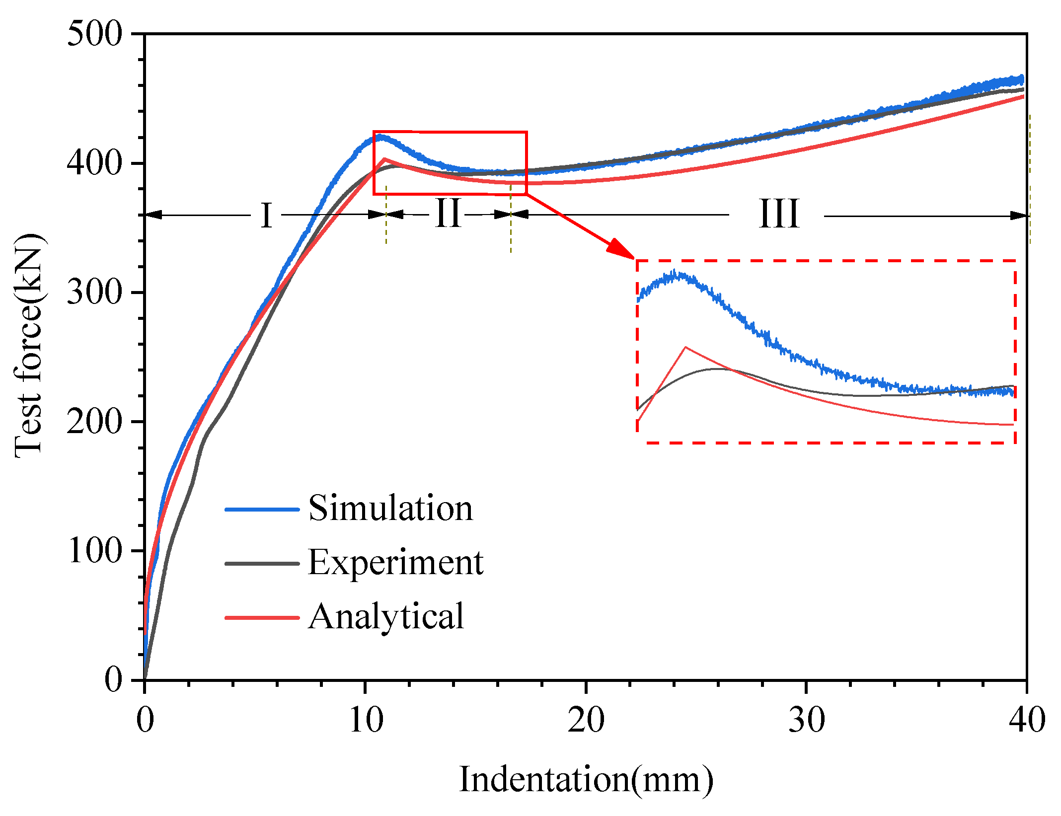
Figure 8 shows the force–displacement curves obtained from the test and the simulation, where the whole compression process can be divided into three stages.
At the beginning of stage I, the initial contact between the indenter and the specimen occurred, and indentation was generated in the local contact region. With the indenter moving downwards, the indentation region expanded, resulting in a rapid rise of the test force. The slope of the force–displacement curve in stage I appeared to vary slightly at first and then gradually decreased. As the indenter moved continually, the upper part of the cruciform yielded gradually and the nonlinear plastic property resulted in variation in the curve slope.
The test results were slightly lower than the simulation results in stage I because the whole test system was not fully fitted in the initial stage of the test. The indenter depth matched well between the simulation and the test once the peak resistance was reached. The maximum values of the test and simulated loads were 397.51 kN and 421.12 kN, respectively, with an error of 5.9%.
In stage II, the instability of the upper part of the cruciform structure led to a reduction in structural resistance. The reduction in the simulation was greater than the experimental result and these two values agreed well by the end of stage II.
In stage III, the instability area of the cruciform expanded, and besides the bending deformation, the component panels of the cruciform produced membrane tensile deformation in their length. The angle between the membrane tensile direction and the loading direction decreased as the indenter moved further downwards. No rupture was found in the specimen during the loading process and the overall structural load-carrying capacity increased steadily. The simulation was in good agreement with the recorded data.
4.2. Deformation
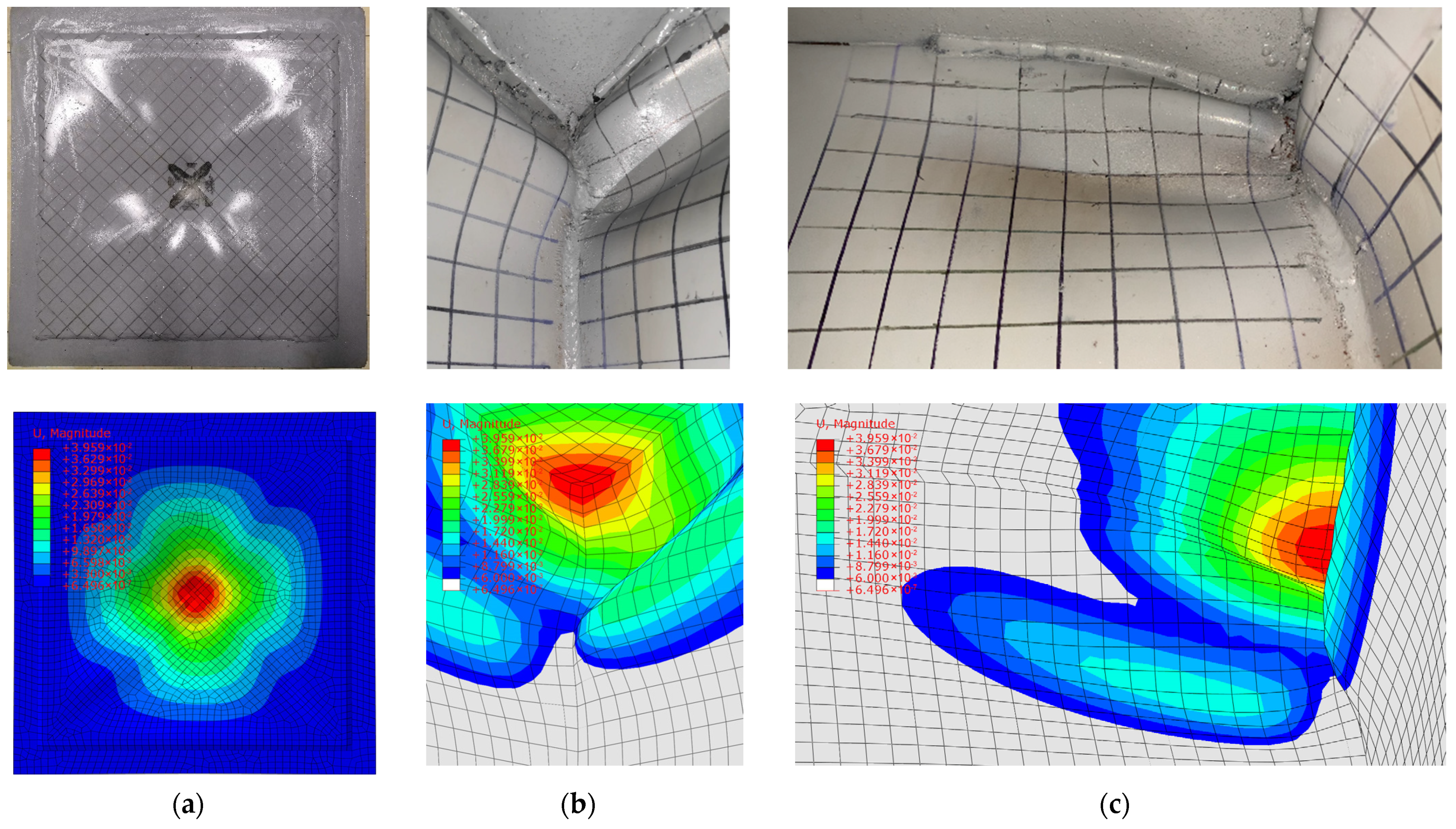
Figure 9 shows the deformation of the specimen in the test and the simulation. It can be seen that the cruciform produced large plastic deformation under the local compression load. A local depression was generated in the center of the surface plate by the pressure of the hemispherical indenter. The uppermost part of the cruciform constrained to the surface plate only underwent downward translation. No significant deflection was found in the mid-axis region of the cruciform, mainly because of mutual support between the four component panels of the cruciform. From the central axis outward, the deflection of the component panels rapidly increased, existing only in the upper part of the cruciform near the contact area of the indenter. The deformation was relatively small for the regions connected with the external frames and away from the loading area.
Observing Figure 9b,c it is straightforward to see that each component plate of the cruciform produced three plastic hinges that divided each plate into three small folds and a large panel at the bottom. The approximate ratio of the maximum height of each fold was 1:3:2. In addition, the deformations of the four component panels were symmetrical about the central axis, and it is straightforward to see in Figure 8b that the two adjacent panels deformed along the same rotational direction. The above deformation modes were used on the simplified deformation pattern of the cross members presented in Section 5.2.
5. Analytical Method
5.1. Upper Bound Theorem
According to the upper limit theorem, the power of work done by external forces is equal to the rate of energy dissipation within the structure, i.e.,
where F is the external force, is the velocity at the point applied with the external force, and is the internal energy dissipation rate. For hull structures, the internal energy dissipation rate can be expressed as
where σij is the stress in the structure, is the strain rate and, according to the Von Mises plastic flow theorem, the plastic energy dissipation rate is
where is the equivalent strain rate of the structure and σ0 is the flow stress. The internal energy dissipation rate of a deformed structure is equal to the sum of the bending deformation energy dissipation rate and the membrane stretching deformation energy dissipation rate.
The bending energy dissipation rate can be expressed as
where Mαβ, , and A are the bending moment, the curvature, and the area of a plate; M0 is the bending moment on a plastic hinge of unit length; for the angular velocity at a plastic hinge; and li is the plastic hinge length. The bending deformation energy includes the continuous bending energy and plastic hinge rotational energy. In general, the energy of bending is ignored in simplified analytical methods, so Formula (12) can be derived from Formula (11).
The membrane stretching energy dissipation rate can be expressed as
where Nαβ is the plane membrane tensile stress tensor and is the equivalent strain rate tensor.
5.2. Deformation Mode and Analysis Method
The damage and deformation of hull structures in a collision and grounding incident are often complex. Simplified analyses of structural responses in realistic scenarios often require reasonable assumptions that can shift the deformation of the theoretical model closer to reality, which is conducive to the derivation of analytical formulae and improving the applicability of analytical methods. Based on the experimental and simulation results, the following assumptions are applied to the deformation of the cruciform structure:
- The deformation of the cruciform is divided into plastic deformation and elastic buckling zones and the dissipation of energy for elastic buckling zones is negligible. In addition, local indentation of the surface plate of the specimen is small, thus its effect on the overall structural resistance is ignored.
- It is assumed that the whole structure produces local compression deformation in the initial stages of loading. The cruciform is destabilized and folds are produced when the indentation depth reaches a threshold value.
- The deflection at the mid-axis region of the cruciform is small, and its effect on the outer part of component panels is not considered. Similarly, the deflection of the elastic buckling zones is small, therefore its effect on the deflection of the folds is neglected.
- Since the structure and the load are symmetrical about the central axis, the deformation modes of the four component panels are similar. The analytical approach in this paper assumes that the deformation of the four panels is identical and symmetrical about the central axis.
- The indenter was loaded at a low constant velocity in the test, so the effect of the material strain rate was ignored in the analytical method.
Considering the assumptions above and the deformation characteristics of the specimen, a new deformation mode for the local in-plane compression of the cruciform is proposed. The whole deformation process is divided into two stages: the initial contact stage and the fold-forming stage. The simplified deformation mode of two stages are as follows:
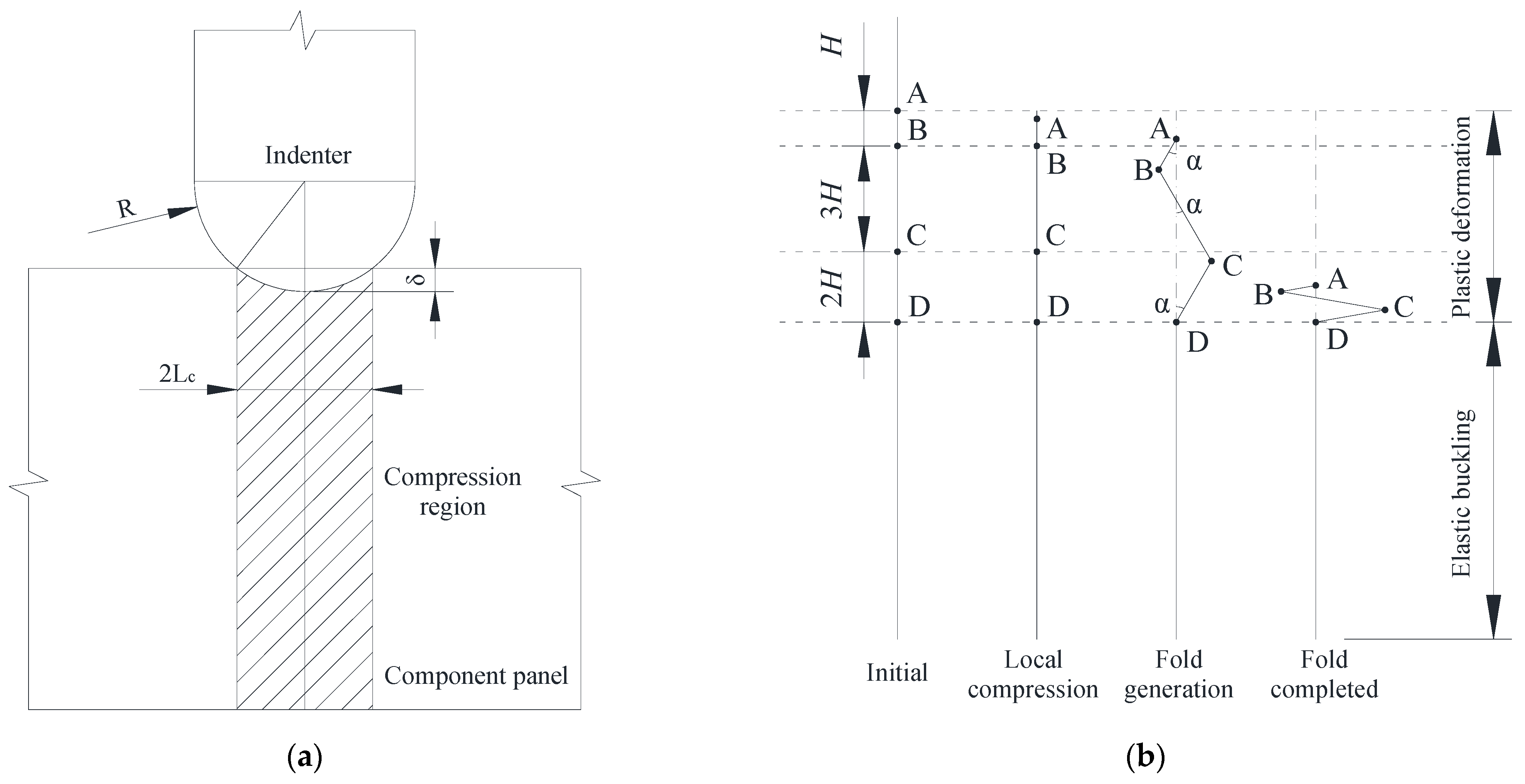
- Figure 10a shows the schematic of the initial contact stage where the cruciform produces local compression deformation without folding. The area of compression is closely related to the depth of indentation and the size of the indenter.
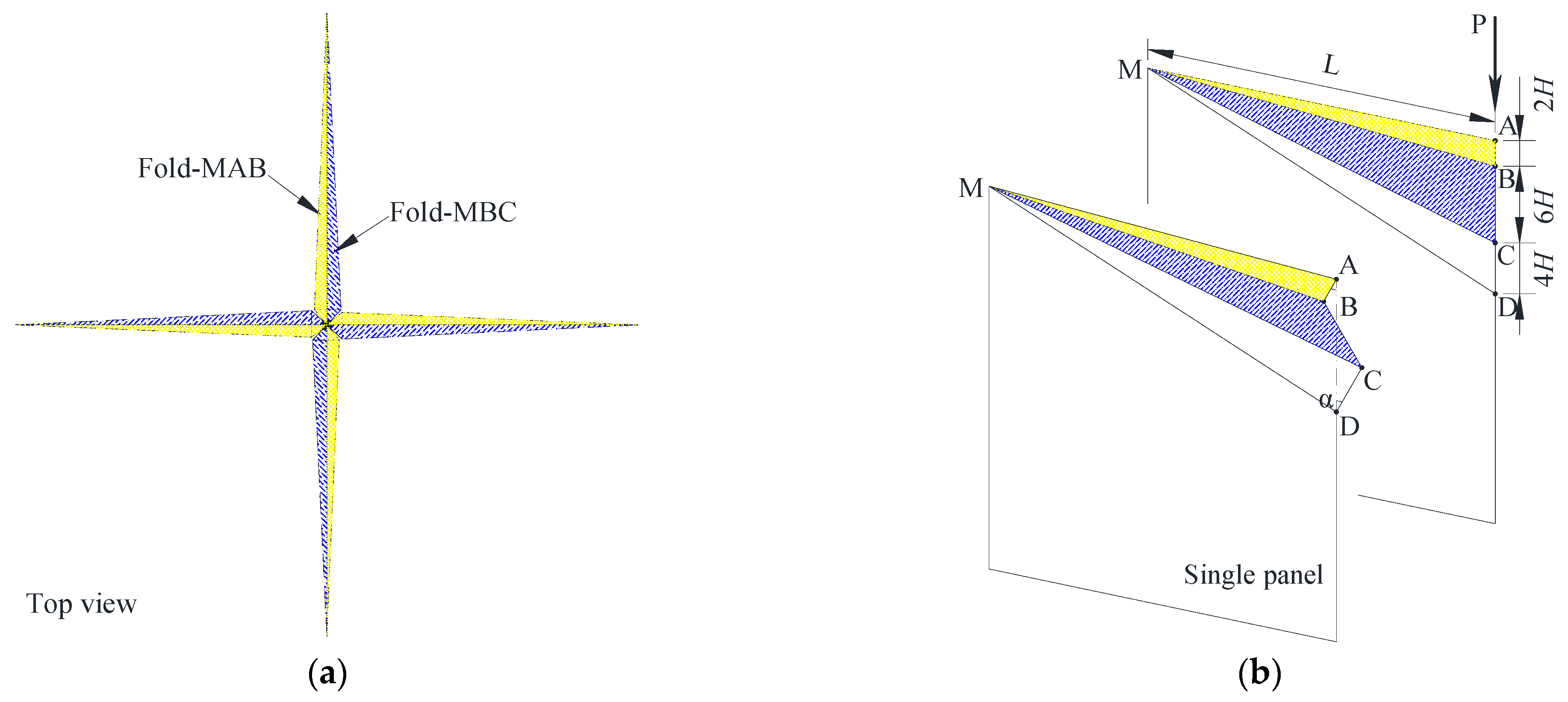
- Figure 10b shows the overall deformation process of a component panel of the cruciform. After the initial stage, plastic hinges and three folds are formed in the plastic deformation zone. The ratio of the maximum width of these folds from top to bottom is 1:3:2, i.e., AB:BC:CD = 1:3:2. The total height of the deformation zone is 6H. Figure 11a shows the deformation schematic of the cruciform, where the deformation of the four component panels is symmetrical about the central axis and the deformed cruciform presents a windmill shape in the top view. Figure 11b shows the fold generating process.
Based on the upper bound theorem and the simplified deformation mode, the deformation energy, the mean crushing resistance, and the instantaneous resistance of the cruciform during deformation are derived. In stage 1, it is assumed that plastic deformation in the weld location occurs at the beginning of compression. In Figure 10a, the width of the compression area in a single panel is Lc. It is assumed that plastic deformation in the weld location occurs at the beginning of the compression. The energy dissipation rate in the first stage is:
where σ0,w is the flow stress; tw denotes the thickness of the cruciform; l denotes the length of the weld, and L denotes the length of a single panel.
During the formation of the folds, a single plate produces plastic deformation in three parts: MAB, MBC, and MCD. The fold is completed when the three parts AB, BC, and CD are completely flattened and the original height of the fold area is 6H. Assuming that the characteristic height of the fold, H, is significantly less than the length of the component panel, the length of the plastic hinge can be regarded as the same as the length of the panel, so that the energy dissipation rate of the plastic hinge in a single panel at this stage is:
where M0,w is the moment on a plastic hinge per unit length and is the angular speed of rotation of the plastic hinge. According to the geometric relationship in Figure 10, the relationship between the indentation depth and the plastic hinge rotation angle is obtained as follows:
Substituting Equation (20) into Equation (17) yields the energy dissipation rate for the plastic hinge of a single panel during fold formation.
The plastic hinge angle α increases from 0 to π/2, so the total energy of the plastic hinge of the single panel is
When the component panels are subjected to in-plane loading, the structure is deformed in membrane tension as well as plastic hinges. Simonsen et al. [31] pointed out that the least energy dissipation occurs when the panel is deformed in tension only along its length. For this reason, only deformations along the length of the panel are considered in the analysis, and the energy dissipation rate for membrane stretching is calculated.
The energy dissipation rate from structural membrane stretching is calculated as:
where N0,w is the tensile force generated by a unit thickness plate during plastic flow, S represents the plastic deformation area; is the average strain rate in the length direction of the plate. The average strain at the plastic hinge MA is
The corresponding strain rate is
Furthermore, MD is the intersection of the plastic deformation zone and the elastic buckling zone, where the strain rate is 0. Considering that the strain rate varies linearly from point A to D, the average strain rates at the plastic hinges MB, MC, and MD are as follows
The average strain rate for the folds was calculated to be
Substituting Equation (30) into Equation (23) yields the energy dissipation rate for the membrane stretching deformation of a single plate during fold generation as
The total energy dissipation of a single plate when the fold is flattened can be obtained by integrating the above equation.
The instantaneous and mean crushing resistance of the cruciform in the second stage of deformation are obtained from Equations (21) and (31) as:
According to the upper bound theorem, the energy dissipation of a structure is minimized at a minimum mean structural resistance.
Substituting Equation (34) into Equation (35) yields H:
The instantaneous and the mean structural resistance of the cruciform at the time of fold generation is obtained by substituting the characteristic height of the fold, H, into Equations (33) and (34). In the case of the indentation test herein, the characteristic height of the folds, the instantaneous structural resistance, and the average structural resistance of the specimens with the load applied at the mid-axis of the specimen are:
The smaller value of Equation (38) is taken as the structural resistance when the cruciform is under pressure.
5.3. Validation of the Analytical Method
The new proposed analytical method was validated with experimental and numerical results. Figure 12 shows the instantaneous resistance of the specimens obtained from the experiment, the numerical simulation, and the analytical method, in which the trend of the three curves matches well.
At the initial period of stage I, the analytical result was in closer agreement with the simulation results, indicating that it is reasonable to assume a certain compression deformation of the cruciform before instability. In the later part of stage I, the analysis showed the increase in collision force slowed down; indeed, the value was smaller than in the simulation result. This is mainly because only the compressive deformation of the cruciform was considered in the analysis. In the real experiment, as the impact depth increased, the surface panel contacting the indenter generated membrane stretching deformation, making the real load higher than the analytical solution.
When the load increased to a certain level, the cruciform buckled and folded, and the load decreased. In stage II, the analytical result was similar to the experimental and simulated trends. The peak collision force in the analysis was 402.67 kN with an error of 1.3%, which was closer to the experimental value, suggesting that the analytical method can predict peak force better.
In stage III, the curves for all three methods followed the same trend. The analytical result was smaller compared to the test and the numerical results, mainly because the analytical method ignored the membrane tensile deformation of the surface panel of the specimen and its contribution to the structural load-carrying capacity.
6. Conclusions
The mechanical response of a cruciform in double-hulled hull structures during collisional grounding accidents was studied experimentally, numerically, and analytically in this paper.
The main conclusions of this study include the following:
- The results of the test and simulations, i.e., the deformation mode and the load-displacement curve of the specimen, were compared. The trend of force displacement curves matched well, and the peak forces of the test and numerical simulations were 397.51 kN and 421.12 kN, with an error of 5%.
- Observations of deformation in the test and the simulated specimen showed that the cruciform structure produced a 1:3:2 ratio of fold heights and that the deformations of four component panels were symmetrical about the central axis.
- By analyzing the deformation mode of the specimen in the test and the simulation, the deformation process of the specimen could be divided into two stages: the initial contact stage and the fold-forming stage. On this basis, a two-stage simplified deformation process of cruciform was proposed. By analyzing the energy dissipation mechanism in each stage, we obtained analytical formulae for predicting the instantaneous and mean resistance of the cruciform under in-plane loading.
- A comparison of the analytical results with the experimental and simulation results showed that the analytical method proposed in this paper can effectively predict the structural resistance of cruciform structures under in-plane loads. The analytical peak resistance was 402.67 kN, closer to the experimental data, indicating that the analytical method provides a more accurate solution.
The test results and the numerical simulation can be of assistance to similar hull structure collisions or groundings, and the analytical method is suitable for the primary design of hull crashworthiness and the rapid evaluation of structural crashworthiness performance.
Author Contributions
Conceptualization, H.L. and X.W.; Writing—original draft, H.L.; Writing—review and editing, Z.G. and K.L.; Visualization, K.L. and J.W. All authors have read and agreed to the published version of the manuscript.
Funding
This research was funded by the National Natural Science Foundation of China (Grant No. 52171311; Grant 52271279).
Institutional Review Board Statement
Not applicable.
Informed Consent Statement
Not applicable.
Data Availability Statement
Not applicable.
Conflicts of Interest
The authors declare no conflict of interest.
Nomenclature
The following abbreviations are used in this manuscript:
| A | plate area |
| Ag | maximum uniform strain |
| C | Rm(e/n)n |
| e | natural constant |
| bending energy dissipation rate | |
| membrane stretching energy dissipation rate | |
| internal energy dissipation rate | |
| F | external force |
| Fw | average structural resistance |
| Fw(δ) | instantaneous structural resistance |
| H | characteristic height of a fold |
| L | length of a single panel |
| Lc | compression width in a single panel |
| l | weld length |
| li | plastic hinge length |
| Mαβ | bending moment |
| M0,w | moment on plastic hinge per unit length |
| Nαβ | plane membrane tensile stress tensor |
| N0,w | tensile force generated by a unit thickness plate |
| n | ln(1 + Ag) |
| Rm | ultimate stress |
| S | plastic deformation area |
| tw | cruciform thickness |
| Greek symbols | |
| α | rotation angle of plastic hinge |
| angular velocity | |
| δ | indentation depth |
| velocity | |
| εe | engineering strain |
| εt | true strain |
| εMA | average strain at the plastic hinge MA |
| average strain rate at the plastic hinge MA | |
| strain rate | |
| equivalent strain rate | |
| average strain rate of a plate in lengthways | |
| σ0/σ0,w | flow stress |
| σe | engineering stress |
| σt | true stress |
References
- Chang, S.E.; Stone, J.; Demes, K.; Piscitelli, M. Consequences of oil spills: A review and framework for informing planning. Ecol. Soc. 2014, 19, 26. [Google Scholar] [CrossRef] [Green Version]
- Oil Tanker Spill Statistics 2021. Available online: https://www.itopf.org/knowledge-resources/data-statistics/statistics/ (accessed on 12 September 2022).
- Urban, J.; Pedersen, P.T.; Bo, C.S. Collision Risk Analysis for HSC. In Proceedings of the 5th International Conference on Fast Sea Transportation, Seattle, WA, USA, 1 January 1999. [Google Scholar]
- Abramowicz, W.; Simonsen, B. Effect of fracture on crushing of ship structures. J. Ship Res. 2003, 47, 194–207. [Google Scholar] [CrossRef]
- Zhou, C.; Li, T.; Ming, S.; Song, Z.; Wang, B. Effects of welding on energy absorption of kirigami cruciform under axial crushing. Thin Walled Struct. 2019, 142, 297–310. [Google Scholar] [CrossRef]
- Ghazijahani, T.G.; Jiao, H.; Holloway, D. Experiments on dented cylindrical shells under peripheral pressure. Thin Wall Struct. 2014, 84, 50–58. [Google Scholar] [CrossRef]
- Mohammed, A.K.; Amdahl, J.; Skallerud, B. Collapse analysis of stiffened panels during accidental conditions. In Proceedings of the Offshore Mechanics and Arctic Engineering, Rio de Janeiro, Brazil, 3–8 June 2001. [Google Scholar]
- Urban, J. Crushing and Fracture of Lightweight Structures. Ph.D. Thesis, Technical University of Denmark, Copenhagen, Denmark, 2003. [Google Scholar]
- Haris, S.; Amdahl, J. Crushing resistance of a cruciform and its application to ship collision and grounding. Ships Offshore Struc. 2012, 7, 185–195. [Google Scholar] [CrossRef]
- Sun, C.; Zhou, J.; Wu, W. Study on Collision of Ship Side Structure by Simplified Plastic Analysis Method. In Proceedings of the 2017 International Conference on Structural, Mechanical and Materials Engineering, Seoul, Republic of Korea, 13–15 July 2017. [Google Scholar]
- Haris, S.; Amdahl, J. An analytical model to assess a ship side during a collision. Ships Offshore Struc. 2012, 7, 431–448. [Google Scholar] [CrossRef]
- Amdahl, J. Energy Absorption in Ship-Platform Impacts. Ph.D. Thesis, The Norwegian Institute of Technology, Trondheim, Norway, 1983. [Google Scholar]
- Wierzbicki, T.; Abramowicz, W. On the Crushing Mechanics of Thin-Walled Structures. J. Appl. Mech-T ASMEs 1983, 50, 727–734. [Google Scholar] [CrossRef]
- Jones, N.; Wierzbicki, T. Structural Crashworthines; Butterworths: London, UK, 1983. [Google Scholar]
- Wierzbicki, T. Crushing behavior of plate intersections. In Structural Crashworthiness; Jones, N., Wierzbicki, T., Eds.; Butterworths: London, UK, 1983; pp. 66–95. [Google Scholar]
- Hayduk, R.J.; Wierzbicki, T. Extensional collapse modes of structural members. Comput. Struct. 1984, 18, 447–458. [Google Scholar] [CrossRef]
- Kierkegaard, H. Ship bow response in high energy collisions. Mar. Struct. 1993, 6, 359–376. [Google Scholar] [CrossRef]
- Hagiwara, K.; Takanabe, H.; Kawano, H. A proposed method of predicting ship collision damage. Int. J. Impact. Eng. 1983, 1, 257–279. [Google Scholar] [CrossRef]
- Abramowicz, W. Crushing Resistance of T, Y and X Sections; Massachusetts Institute of Technology: Boston, MA, USA, 1994. [Google Scholar]
- Liu, K.; Zong, S.; Li, Y.; Wang, Z.; Hu, Z.; Wang, Z. Structural response of the U-type corrugated core sandwich panel used in ship structures under the lateral quasi-static compression load. Mar. Struct. 2022, 84, 103198. [Google Scholar] [CrossRef]
- Park, S.-J.; Choung, J. Punching Fracture Experiments and Simulations of Unstiffened and Stiffened Panels for Ships and Offshore Structures. J. Ocean. Eng. Technol. 2020, 34, 155–166. [Google Scholar] [CrossRef]
- Cerik, B.C.; Shin, H.K.; Cho, S.-R. On the resistance of steel ring-stiffened cylinders subjected to low-velocity mass impact. Int. J. Impact. Eng. 2015, 84, 108–123. [Google Scholar] [CrossRef]
- GB/T228.1-2010; Metallic Materials-Tensile Testing-Part 1: Method of Test at Room Temperature. China Standard Press: Beijing, China, 2011.
- Dieter, G.E. Mechanical behavior under tensile and compressive loads. Asm Handb. 2000, 8, 99–108. [Google Scholar]
- Dassault Systèmes. Abaqus, version 2018. Windows. Dassault Systèmes: Paris, France, 2018.
- Alsos, H.S.; Amdahl, J.; Hopperstad, O.S. On the resistance to penetration of stiffened plates, Part II: Numerical analysis. Int. J. Impact. Eng. 2009, 36, 875–887. [Google Scholar] [CrossRef]
- Villavicencio, R.; Soares, C.G. Numerical plastic response and failure of a pre-notched transversely impacted beam. Ships Offshore Struc. 2012, 7, 417–429. [Google Scholar] [CrossRef]
- Dieter, G.E.; Bacon, D. Mechanical Metallurgy; McGraw-Hill: New York, NY, USA, 1976. [Google Scholar]
- Zhang, L.; Egge, E.-D.; Bruhns, H. Approval Procedure Concept for Alternative Arrangements; Germanischer Lioyd: Hamburg, Germany, 2004. [Google Scholar]
- Liu, K.; Lu, Y.; Wang, Z.; Wang, G. An experimental, numerical and analytical study on deformation mechanisms of web girders in a collision or grounding incident. Ships Offshore Struc. 2019, 14, 839–852. [Google Scholar] [CrossRef]
- Simonsen, B.C.; Ocakli, H. Experiments and theory on deck and girder crushing. Thin Wall Struct. 1999, 34, 195–216. [Google Scholar] [CrossRef]
Figure 1.
Typical collision and grounding scenario of double-hull amidship.

Figure 2.
(a) The geometric dimension, (b) the exploded view, and (c) the bottom view of the specimen.
Figure 2.
(a) The geometric dimension, (b) the exploded view, and (c) the bottom view of the specimen.

Figure 3.
(a) The quasi-static indentation test setup, (b) the universal testing machine, and (c) the photo of tensile test.
Figure 3.
(a) The quasi-static indentation test setup, (b) the universal testing machine, and (c) the photo of tensile test.

Figure 4.
(a) Schematic of tensile specimen; (b) engineering stress–strain curves of three tests.

Figure 5.
(a) Details of the finite element model; (b) weld elements utilized in different parts of the specimen.
Figure 5.
(a) Details of the finite element model; (b) weld elements utilized in different parts of the specimen.

Figure 6.
Force–displacement curves for coarse, medium, and fine meshed models.

Figure 7.
The combined material relationship of mild steel.

Figure 8.
Comparison of crushing response between experiment and simulation.

Figure 9.
Deformation diagrams of (a) the surface panel, (b) the cruciform, and (c) a single component panel.
Figure 9.
Deformation diagrams of (a) the surface panel, (b) the cruciform, and (c) a single component panel.

Figure 10.
(a) Diagram of the initial contact between the indenter and the specimen; (b) deformation process of a component panel in the cruciform subjected to in-plane compression.
Figure 10.
(a) Diagram of the initial contact between the indenter and the specimen; (b) deformation process of a component panel in the cruciform subjected to in-plane compression.

Figure 11.
The deformation mode of the cruciform: (a) a top-view image of four symmetrical component panels; (b) the deformation process of a single panel.
Figure 11.
The deformation mode of the cruciform: (a) a top-view image of four symmetrical component panels; (b) the deformation process of a single panel.

Figure 12.
Comparison of crushing response between the experimental, numerical, and analytical methods.
Figure 12.
Comparison of crushing response between the experimental, numerical, and analytical methods.


Table 1.
Comparison of current study versus previous works on the resistance of cruciform structures.
Table 1.
Comparison of current study versus previous works on the resistance of cruciform structures.
| Refs. | Material | Indenter | Method | ||
|---|---|---|---|---|---|
| Experimental | Analytical | Numerical | |||
| [3] | Aluminum alloy | Flat indenter | X | X | |
| [4] | Mild steel, aluminum alloy | Flat indenter | X | ||
| [5] | Mild steel | Flat indenter | X | X | |
| [7] | Mild steel | Flat indenter | X | ||
| [8] | Aluminum alloy | Flat indenter | X | ||
| [9] | Aluminum alloy | Flat and ellipsoidal indenter | X | X | |
| [16] | Aluminum alloy | Flat indenter | X | X | |
| This paper | Mild steel | Hemisphere indenter | X | X | X |
Table 2.
Mechanical properties of material.
| Properties | Unit | |
|---|---|---|
| Density | kg/m3 | 7850 |
| Young’s modulus | GPa | 213 |
| Poisson’s ratio | - | 0.3 |
| Yield stress | MPa | 221 |
| Ultimate tensile strength | MPa | 353 |
| Rupture strain | - | 0.35 |
Disclaimer/Publisher’s Note: The statements, opinions and data contained in all publications are solely those of the individual author(s) and contributor(s) and not of MDPI and/or the editor(s). MDPI and/or the editor(s) disclaim responsibility for any injury to people or property resulting from any ideas, methods, instructions or products referred to in the content. |
© 2023 by the authors. Licensee MDPI, Basel, Switzerland. This article is an open access article distributed under the terms and conditions of the Creative Commons Attribution (CC BY) license (https://creativecommons.org/licenses/by/4.0/).
Share and Cite
MDPI and ACS Style
Liu, H.; Liu, K.; Wang, X.; Gao, Z.; Wang, J. On the Resistance of Cruciform Structures during Ship Collision and Grounding. J. Mar. Sci. Eng. 2023, 11, 459. https://doi.org/10.3390/jmse11020459
AMA Style
Liu H, Liu K, Wang X, Gao Z, Wang J. On the Resistance of Cruciform Structures during Ship Collision and Grounding. Journal of Marine Science and Engineering. 2023; 11(2):459. https://doi.org/10.3390/jmse11020459
Chicago/Turabian StyleLiu, Hewei, Kun Liu, Xiufei Wang, Zhenguo Gao, and Jiaxia Wang. 2023. "On the Resistance of Cruciform Structures during Ship Collision and Grounding" Journal of Marine Science and Engineering 11, no. 2: 459. https://doi.org/10.3390/jmse11020459
Note that from the first issue of 2016, this journal uses article numbers instead of page numbers. See further details here.