1. Introduction
Ships are responsible for almost all world trade; in fact, about 90% of goods are transported by sea [
1]. Maritime transport allows moving large quantities of goods in an economic, efficient and sustainable way, even over long distances [
2]. Passenger transport by sea also has a relevant role. The world fleet is composed of about 120,000 ships (having more than 100 GT), and 7.6% of them are passenger ships [
3]. The data for the year 2019 show that passenger ships transported about 29.7 million people [
4]. Among these vessels, a significant percentage is made up of cruise ships, especially as regards the turnover generated. As a matter of fact, in 2021, despite the limitations imposed to fight the COVID-19 pandemic, cruise ship industry revenues reached USD 13.6 billion [
5]. The forecasts for 2023 suggest that the number of passengers and revenue will return to the levels of 2019 [
5].
The indissoluble link between the global economy and international transport by sea identifies the weight that shipping has in terms of emissions of pollutants and greenhouse gases (GHG), due to the volume of traffic involved. Phenomena such as climate change and rising temperatures, associated with the release of these substances, have led governments and international bodies to issue regulatory measures for greening the maritime industry. In this framework, international regulations such as the Paris Agreement [
6] and the International Maritime Organization (IMO) resolutions [
7] were issued to impose limitations on emissions of pollutant substances. Among these substances, greenhouse gases (GHGs) must be reduced the most; indeed, according to the IMO, their quantity at entire fleet level is expected to sit at 50% by 2050 with respect to the 2018 levels, with a specific measure regarding carbon dioxide (CO
2) that requires a reduction of 70% per transport work [
7]. In addition to the aforementioned regulations, the European Union (EU) introduced resolutions aimed at addressing climate changes that are in force within the EU area and its inbound and outbound transport routes, such as the “Fit for 55” policy. The most relevant rules introduced by the EU are an emission trading system for maritime transport (similar to the one already existing for land producers), the FuelEU Maritime Initiative and the Energy Taxation Directive. In particular, the FuelEU imposes a maximum tier on a quantity that could be defined as the GHG intensity of the energy used on board ships, and requirements regarding power supply modes and emissions levels at berth in ports. As a target, the 2020 fleet average level of GHG intensity should be reduced starting from 2025 and should reach a reduction of 75% by 2050 [
8]. As for the Energy Taxation Directive, it aims at promoting sustainable and environmentally friendly fuel usage; hence, it introduces a new taxation structure that impacts fuel and electricity and is based on the energy efficiency and environmental performance of vessels.
Therefore, in response to recent regulatory limits, the challenge of energy transition has also begun in the maritime sector, which requires its major players to make decisions that are difficult to predict and have a great impact on the future of shipping and the related production chains.
To increase the energy efficiency of ships and reduce their environmental impact across time, different strategies have been developed and tested with an increasing impact on the structure of the vessel [
9]. In the passenger ship sector, and in particular for cruise ships, the keyword immediately identified was
vehicle electrification. Many innovative technologies have found application on board passenger ships, integrating appropriate storage systems for energy so that it can be available at the right time [
10]. For small- and medium-sized ships (<30,000 GT), the optimal solution proved to the application of hybrid-electric propulsion systems with battery-based storage systems [
11]. For large ships that may need up to 80 MW, the available technologies are not yet mature enough to be used on board. In other words, it is still early for disruptive innovations and it is necessary to identify a technological roadmap that allows the incremental achievement of the decarbonization result using technologies that are mature or are maturing in the short term. The greater risk is the loss of performance/payload. Many new fuels are being tested even though it is worth remembering that traditional diesel engines have an exceptional efficiency of 52%. In any case, a fundamental issue to address will be the cold ironing/recharging of the energy storage systems installed on board in port [
12].
In this article, after a description of the technologies already or soon-to-be available on the market, a reference 112,000 GT ship was selected to estimate and present the impact of the adoption of new fuel/generation systems in terms of capacity and consumption. Although cruise ships represent just a small part of the maritime transport sector, their choice is justified by their complex layout compared to merchant vessels along with their peculiar operative profile. Cruise ships should satisfy relevant hotel loads even at berth, having a higher environmental impact in port [
13]. Considering that they are often berthed near city centers and that their operation is far less justifiable to the general public compared to merchant vessels, defining strategies towards passenger ships’ ecological transition is a primary concern. Furthermore, the introduction of alternative fuels and new power-generation technologies is far more challenging in terms of space availability and impact on range on a cruise ship compared to merchant vessels, where new storage might be fitted on main deck or beside/beneath the superstructure [
14]. In this work, the focus is on technical aspects, leaving aside other primary concerns such as emissions (that can be easily computed from fuel consumption rates by applying proper emission factors) or economic aspects (due to the current volatility of the market and unpredictable effects of an increase in the demand for green fuels). Subsequently, step-by-step innovation solutions will be proposed with the aim of providing a series of technology mixes specifically suited to passenger ships, assuming improvements in the efficiency of the components. Specifically, the focus will be on liquid natural gas (LNG) and two alternative fuels applicable to the cruise sector: ammonia (AMM) and liquid hydrogen (HYD). They have been considered as the most challenging due to their temperature, toxicity and storing/fuel system compared to other viable options such as methanol. In fact, methanol can be stored in structural tanks at atmospheric pressure and temperature like traditional fuels. Thus, due to its volumetric energy density, it just implies a reduction in range if cruise ship layout is kept as it is. On the other hand, AMM, LNG, and HYD are far more challenging since they require special containment systems, which have a significant impact on cruise ship internal layout.
2. Technology Overview
In this section, an overview of the conventional energy-generation system on cruise ships is presented first. Then, the effects of the application of LNG as a transition fuel towards decarbonization are discussed. Furthermore, alternative fuels (ammonia and hydrogen) and the technological implications/challenges of their adoption on a cruise ship are discussed. The focus is on internal combustion engines (ICEs) and two of the most promising types of fuel cells in the maritime fields.
2.1. Conventional Energy-Generation System on Cruise Ships
Nowadays, most existing ships utilize liquid fossil fuels [
15]. Specifically, 47% of ships in the world fleet, corresponding to 69% of total gross tonnage, still use heavy fuel oil (HFO) as primary fuel [
16]. In 2017, 76% of marine fuel consumed was HFO, whereas 23% was marine diesel oil (MDO) [
17]. The most important parameter when dealing with fossil fuels is the carbon/hydrogen (C/H) ratio, which impacts the main fuel characteristics, e.g., density, viscosity, heat value, etc. Liquid fossil fuels are composed of a mixture of hydrocarbons derived from crude oil distillation at different temperatures. These fuels are employed in ICEs, which convert the fuel chemical energy into mechanical energy.
The combustion creates five main types of pollutants: carbon dioxide (CO
2), the most relevant greenhouse gas, sulfur oxides (SO
X) depending on the sulfur content in the fuel, nitrogen oxides (NO
X) depending mostly on the combustion temperature, particular matter (PM), divided into PM0.1, PM2.5, and PM10 based on particle size, and volatile organic compounds (VOC). Recently, several international regulations stated limits for pollutants emissions; in particular, the sulfur content in liquid fuels and the emissions of NO
X and CO
2 were regulated through the introduction of the Energy Efficiency Design Index (EEDI), Energy Efficiency Existing Ship Index (EEXI), and Carbon Intensity Indicator (CII) limits [
9,
18]. These led to the adoption of devices to treat exhaust gases such as scrubbers for SO
X [
19,
20] and selective catalytic reduction (SCR) reactors for NO
X [
21,
22]. These systems require additional capital, operative costs, and space (especially scrubbers), leading to larger engine casing that reduces ships’ payload (i.e., number of cabins and area of public spaces).
However, these systems do not radically change the energy-generation/distribution system of conventional cruise vessels fueled with MDO or HFO, which represent the large majority of the world fleet. Most cruise ships have diesel-electric propulsion systems. Usually, four to six 4-stroke ICE generators are located in two separate watertight compartments. Then, the electric power is distributed through the main switchboards to the propulsion electric motors (PEMs) and all the other systems which use electricity (e.g., conditioning systems, auxiliaries, lighting systems, navigation systems, etc.). Hence, two propellers are driven by two PEMs that can be located on board (connected through traditional shaft lines) or in pods. In conventional cruise vessels, fuel is stored in structural tanks, usually located in the double bottom.
2.2. LNG as a Transition Fuel
Starting from the beginning of this century, the development of dual-fuel 4-stroke engines capable of utilizing both liquid fuels and natural gas fostered the application of LNG as a marine fuel. In the 2010s, the applicability of this technology was improved by the introduction of 2-stroke dual-fuel engines into the market that became an interesting alternative for merchant ships. LNG, obtained by purification and liquefaction of natural gas, is the greenest fossil fuel, having reduced emissions of all the main pollutants when used in 4-stroke ICEs (CO
2 reduction about 20–30%, NO
X 80–85%, SO
X 92–99%, PM 95–97% [
23,
24,
25,
26]). Nevertheless, natural gas has 28–34 times higher global warming potential compared to CO
2. Hence, in the long term, the emissions of unburned methane coming from LNG-fueled ships (methane slip) might provide a relevant contribution to climate change and should be limited by dedicated rules [
27]. Nonetheless, LNG-fueled ships comply with current international regulations for emissions without the need for scrubbers or SCR systems. This aspect, along with the lower price compared to liquid fuels in recent decades, has driven an increase in LNG-fueled ships and a continuous development of bunkering facilities [
28]. Now, about 2% of the world fleet is LNG-fueled [
15] with an increasing share in new orders. LNG has good technological maturity and a well-defined rule framework [
29]. Therefore, it can be considered a good transition fuel, moving towards greener and alternative ones [
30].
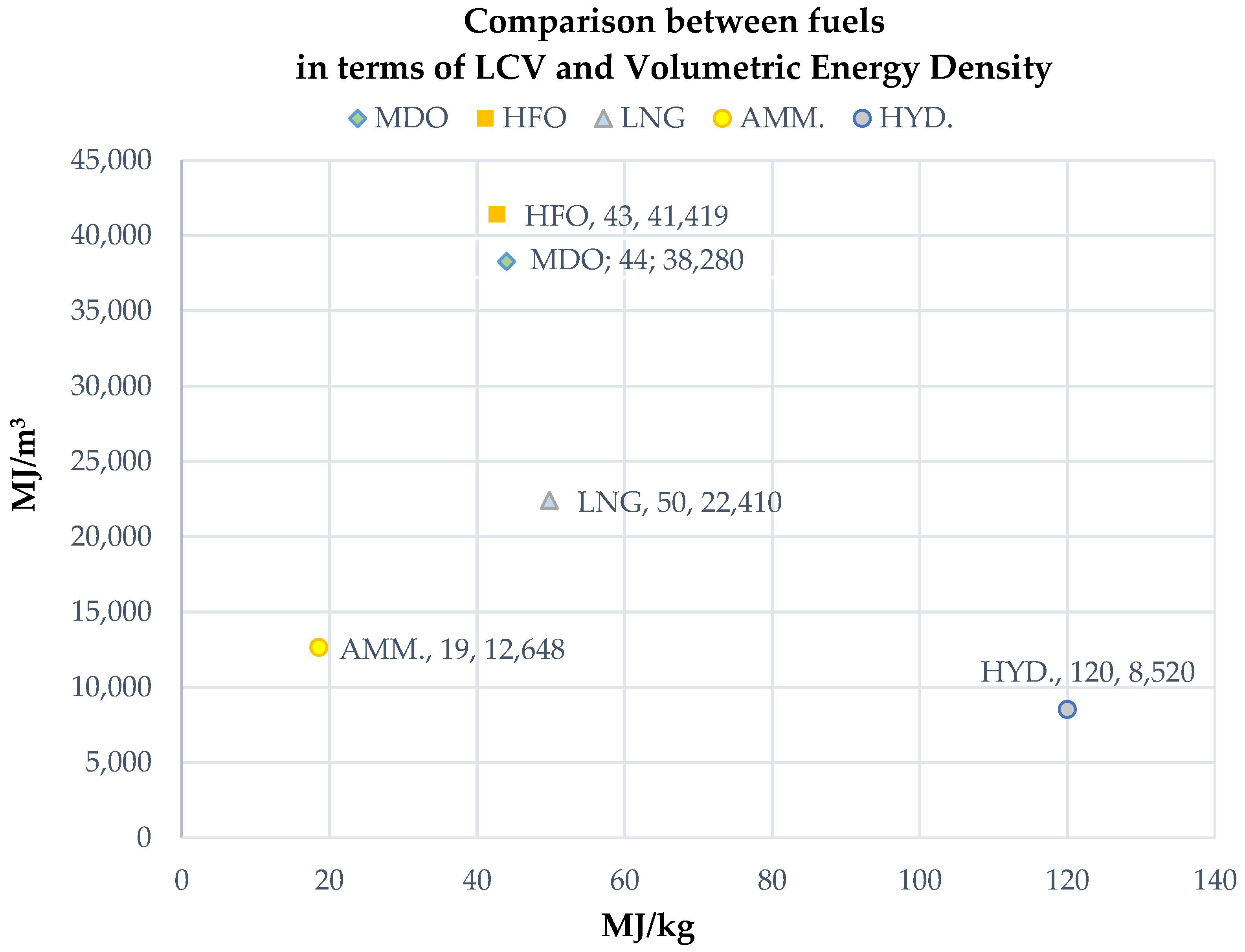
On a cruise ship, ICE dual-fuel generators are currently used. Hence, the conventional energy-generation and distribution systems are only slightly affected by the introduction of LNG as a marine fuel. The main changes compared with traditional solutions concern fuel storage and the fuel systems (from storage to ICEs), which can be combined in a dedicated module. LNG requires a storage temperature of about −163 °C to maintain its liquid state. Hence, it should be stored in insulated cryogenic tanks. Moreover, the IGF code states specific requirements regarding the positioning of these storage tanks; they should be located at proper distances from the side shell and bottom. In addition, LNG has a lower volumetric energy density compared to liquid fossil fuels (
Table 1,
Figure 1). Thus, keeping constant the stored energy, the required tank volumes of LNG are 1.2 times those of HFO. Considering the insulation and shape of storage spaces, a more realistic volume factor related to HFO is greater than 2 [
31].
Regarding the containment system, four categories can be defined according to IGF code [
29]:
IMO Type-A: self-supporting independent prismatic tanks with two barriers (the second enclosing the tank and capable of containing LNG for 15 days. LNG should be maintained at −163 °C at a pressure lower than 0.7 bar. They are independent of ship structure and usually prefabricated using 9% nickel steel, stainless steel, and/or aluminum.
IMO Type-B: similar to IMO Type-A but having only a partial secondary barrier, still capable of containing LNG for 15 days. They are usually made of 9% nickel steel and/or high-manganese steel.
IMO Type-C: single-barrier self-sustaining tanks having cylindrical, bilobate, or trilobate design. They imply the worst space utilization compared to other types, but they can operate at pressures higher than 2 bars. They are independent of ship structure, usually prefabricated using 9% nickel steel and can be fitted below deck or on the open decks.
Membrane: prismatic tanks supported by ship structure with two barriers. They should be constructed inside the pre-manufactured tank compartment and are usually made of stainless steel. As with IMO Types A and B, LNG should be maintained at −163 °C at a pressure lower than 0.7 bar.
2.3. Alternative Fuels
Although greener than traditional fuels, LNG is still a fossil fuel that implies relevant emissions of GHG. To move towards climate-neutral shipping, several alternative marine fuels have recently been proposed and tested. As mentioned, in this work, ammonia and hydrogen will be investigated.
Ammonia is a colorless, toxic, corrosive gas that contains no carbon and, thus, cannot generate CO
2 when used as fuel. In fact, the following combustion reaction applies to ammonia:
Ammonia is not present in kind; thus, it is produced by combining hydrogen (H
2) and nitrogen (N
2). Depending on the production process, it is classified as gray, blue, or green ammonia. Gray and blue ammonia are produced from methane using the Haber–Bosch process that emits carbon dioxide. If the process is combined with carbon capture, blue ammonia is obtained, otherwise, it is classified as gray. Green ammonia is produced through electrolysis using renewable energy for electricity generation (e.g., wind, solar energy, etc.) [
32]. Ammonia can be stored in liquid phase at −33 °C at atmospheric pressure. Thus, although temperatures are higher compared to LNG, it should be stored in cryogenic tanks made of proper materials to avoid corrosion. Additionally, the fuel system should avoid materials such as mild steel with impurities/contaminants that are corroded by ammonia. Ammonia presents boil-off rates of about 0.025% [
33], which can increase the pressure inside the tank and should be re-liquefied to avoid spills in the atmosphere. Ammonia is extremely dangerous compared to LNG, although it is less flammable. LNG is mostly composed of methane, which is a powerful GHG, but ammonia is toxic for humans and other living beings. Thus, a gas spill can generate a toxic atmosphere whereas a liquid spill in water might cause serious environmental damage due to ammonia’s solubility in water.
Hydrogen (H
2) is a non-toxic, odorless, and colorless gas that is not present in kind. The combustion reaction for hydrogen is:
Similar to ammonia, hydrogen can be classified as gray, blue, or green depending on the production process. Gray hydrogen is obtained through steam methane reforming (SMR) or auto thermal reforming (ATR) which splits the natural gas into hydrogen and CO
2. Blue hydrogen is produced with the same process, but CO
2 is captured instead of being emitted into the atmosphere. Green hydrogen is produced using electrolysis from water using renewable sources. Although non-toxic, hydrogen is extremely flammable (flammability range between 4% and 75% by volume of air and a self-ignition temperature of 571 °C); thus, fuel storage should be subject to strict safety requirements [
34]. Liquid hydrogen should be stored at temperatures lower than LNG (about −253 °C at atmospheric pressure), with increased insulation and boil-off issues [
15].
As shown in
Table 1 and
Figure 1, the main issue related to all alternative fuels is related to the volumetric energy density. In fact, to store the same energy, a 3.3 times larger volume is required than HFO for liquid ammonia and about 5 times for liquid hydrogen. These volumes are even larger considering the need for cryogenic tanks compared to structural tanks [
35]. Liquid hydrogen, despite having a very high energy density per unit of mass, has a density of 71 kg/m
3. This leads to unreasonable fuel storage volumes to keep the ship range constant or, alternatively, a considerable reduction in ship range.
2.4. Innovative Technologies Associated with Alternative Fuels
Considering the combustion reactions, ammonia and hydrogen are very promising marine fuels to meet the shipping decarbonization targets stated by the IMO. Hydrogen 4-stroke marine engines are already available on the market. Their application has been limited by previously discussed storage issues and the unavailability of bunkering facilities. Ammonia can be also used in modified ICEs that are in advanced development status. Currently, a primary engine manufacturer has already carried out experimental trials of an engine burning a fuel blend composed of 70% ammonia and 30% hydrogen [
36,
37], whereas full-ammonia 4-stroke and 2-stroke engines are expected to reach the market by 2023 and 2024, respectively [
38]. As mentioned, the combustion does not produce CO
2, but, due to the ammonia slip phenomenon, NO
X is still produced. Thus, an SCR system is required within the exhaust gas system. Due to its peculiar characteristics, the use of pure ammonia is not recommended. In fact, as well as having a rather high auto-ignition temperature, a low volumetric flammability range, and a low propagation speed of the flame front, ammonia requires higher compression ratios. Moreover, the ammonia slip phenomenon is responsible for nitrogen oxides emissions and lower efficiency of the combustion itself. For all these reasons, the common strategy consists of lowering temperatures and making it as homogenous as possible by means of an optimal premixing of ammonia and hydrogen before injection.
The hydrogen for the fuel mixture or pilot flame is not necessarily required to be stored in a dedicated tank, but can be directly produced on board through ammonia cracking. In a cracker, hydrogen is produced using the following endothermic reaction [
32]:
The cracker requires a heat source (46.22 kJ/mol) that can be partially provided to the catalyst using exhaust gas energy recovery or from the engine cooling system. Such a process can be also applied to systems using hydrogen, to avoid the flammability risk, and partially solve the fuel storage issues; ammonia can be stored in tanks at higher temperatures exploiting the higher energy density compared to hydrogen. Then, hydrogen can be produced on board by cracking ammonia.
Aside from ICEs, in order to avoid the generations of NO
X, fuel cells (FCs) might be applied. An FC directly converts the chemical energy contained in a fuel into direct electric current (DC) using an exothermic electrochemical process (fuel oxidation) [
39]. Thus, they do not require several systems (e.g., scrubbers, SCRs, boilers, and ICEs auxiliaries). These saved spaces can be assigned, for instance, to additional fuel storage volumes. Considering a power-generation system based on FCs, it should be noted that FC output voltage is not regular, thus, a voltage converter (DC-DC) should be installed downstream. Then, for ships with alternating current (AC) distribution systems, an inverter (DC/AC) is needed before connecting the main switchboard. Moreover, FCs’ load cannot be rapidly changed as happens for ICEs gensets. Thus, when FCs are employed, an energy storage system is also required to sustain fast change in electric power demand (e.g., during maneuvering) [
40]. Hence, a power system based on FCs is, by definition, a hybrid-series propulsion system [
41,
42], also enabling the application of additional benefits in terms of energy efficiency, such as peak shaving [
43]. The remaining electrical distribution system will be similar to the conventional ones installed on ships fueled with HFO, MDO, or LNG. Here, there will be a focus on the following two types of fuel cells for marine application: proton exchange membrane fuel cell (PEMFC) and solid oxide fuel cell (SOFC).
PEMFCs are a mature technology and the most common FC on the market [
44]. They can use only hydrogen gas; thus, they require a purifier to remove any other substance from the fuel. Therefore, if ammonia is employed as an onboard energy storage, a cracker is required too, in order to produce hydrogen. Moreover, since PEMFCs operate at temperatures about 80–100 °C (FC based on Nafion), they require a cooling and ventilation system. PEMFCs’ efficiency ranges from 45% to 60%; for calculation purposes, 55% can be assumed, also accounting for the efficiency of cooling pumps and ventilation systems [
45]. A single PEMFC module has a maximum power of about 120 kW. Therefore, multiple FCs are required for marine applications. Based on the specifications provided by the manufacturers, the energy density and overall dimensions of a fuel cell system can be roughly estimated as a function of the required installation power. The power–weight density of a PEMFC, in combination with auxiliary cooling systems, is about 250–1000 kW/t and 300–1500 kW/m
3 [
46]. PEMFCs can operate from a 6% load up to the nominal power. Thus, it is recommended to switch off some modules to reduce consumption at low load, as is already the case when using diesel generator sets [
32].
SOFCs can be fueled with several different fuels including hydrogen (even non-pure), ammonia, and LNG [
44,
47]. Therefore, it is not required to install a cracker on board to produce hydrogen from ammonia. SOFCs operate at higher temperatures compared to PEMFCs (about 600–800 °C) and are available in modules with 1–2 MW of nominal power. SOFCs have an electric efficiency of about 60% with the application of heat recovery systems [
45,
48]. The main drawback of SOFCs is the lower power density compared to PEMFCs: about 8–80 kW/t and 4–32 kW/m
3 [
46]. Furthermore, they are less flexible; start-up requires several hours and they are slower in load changing compared to PEMFCs. Finally, if they are fueled with LNG, SOFCs are not carbon-neutral, since CO
2 is emitted.
3. Reference Ship
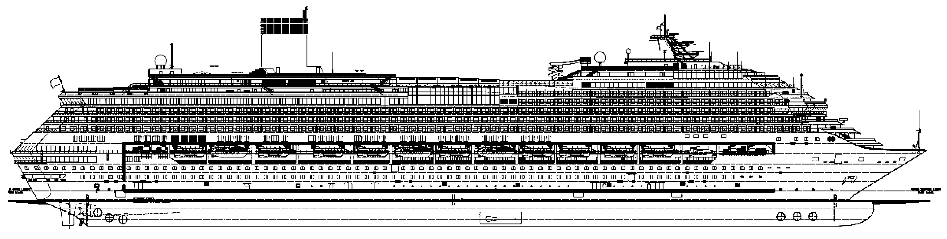
For this study, a 112,000 GT passenger ship able to transport approximately 5000 people (passengers and crew) has been selected (
Figure 2). The main characteristics of the reference ship are reported in
Table 2. Cruise ships of this size are the most popular on the market and have an average age of over 10 years. For these ships, shipowners must decide what to change during the mid-life revamp as regards their energy efficiency and the possible installation of new systems for propulsion and generation on board.
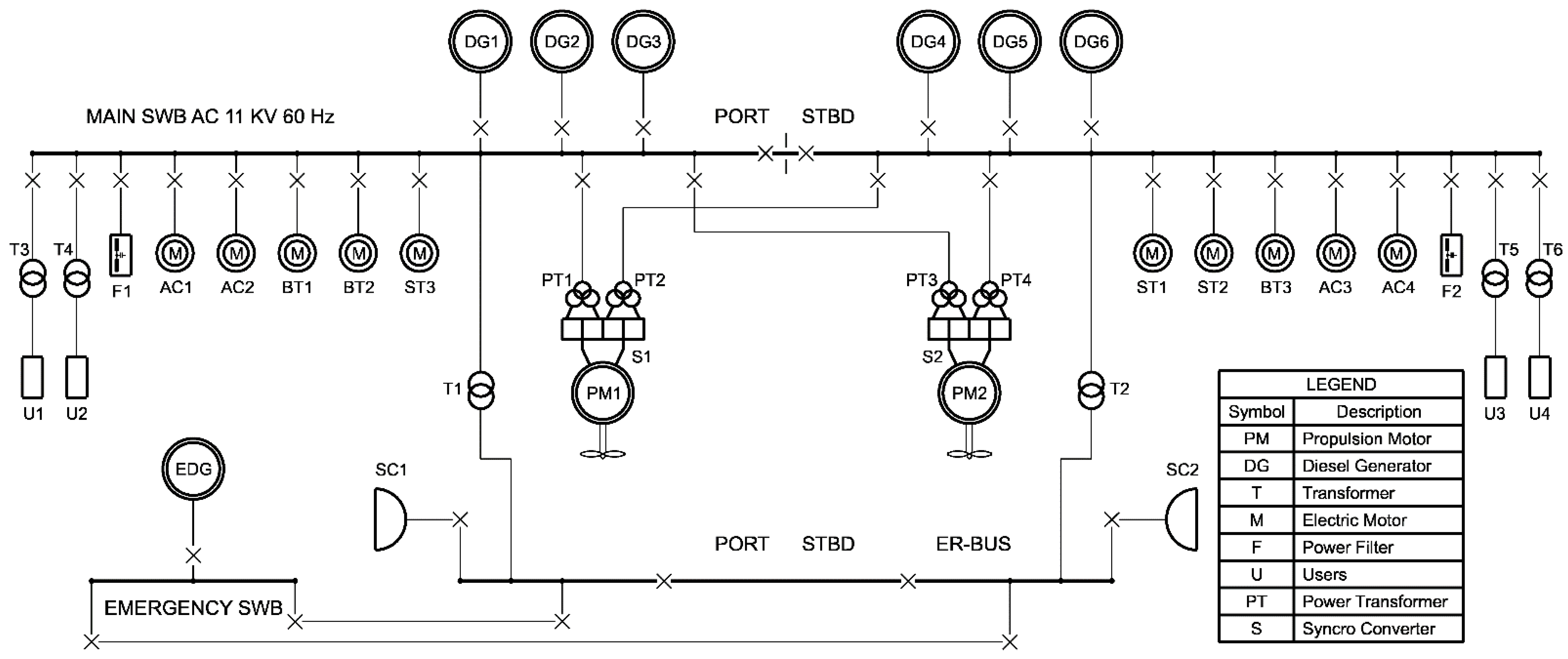
Ship propulsion is performed through a diesel-electric layout, in which six 12.6 MW diesel generators (DGs) power the ship in the various operational configurations. Considering an alternator efficiency equal to 97%, each DG provides an electric power equal to 12.2 MW for a total equal to 73.3 MW.
The ship is equipped with six 1720 kW transverse thrusters, three forward and three aft, two propellers powered by two 21 MW electric motors, two rudders, and stabilizing fins. The onboard electrical system redistributes the power through the onboard control unit in medium and low voltage (11 kV-440 V-220 V, three-phase, 60 Hz).
3.1. Fuel Used
The main fuel used by the reference ship is the HFO. This is stored in numerous tanks located in the ship double bottom; the total capacity, including settling and service tanks, is approximately 3665 m
3.
Table 3 shows the total amount of energy stored on board calculated through the fuel LCV that will serve as a comparative term with the solutions based on alternative fuels provided in
Section 4.
In addition, for specific operational conditions, the ship is powered through MDO, which is stored in tanks having a total capacity equal to 227 m3.
3.2. Energy Balance and Shipboard Power System Layout
The energy balance calculation is crucial to estimate the energy needs for propulsion, maneuvering, and hoteling at berth. Furthermore, for the reference ship, both the cruise and the maximum speed have been considered.
Table 4 shows the results obtained for the energy balance in terms of power required for the considered conditions and load factors for the onboard DGs.
As a contractual requirement, the shipboard power system (shown in
Figure 3) has to guarantee a cruise-speed navigation taking into account a value for sea margin (SM) equal to 25% and an auxiliary load equal to 10.5 MW. From the results shown in
Table 4, it is evident that the use of four DGs out of six is more convenient for such conditions; in fact, the load factor value is close to 83% of the maximum continuous rating (MCR) and this ensures a better energy efficiency with a consequent reduction in terms of specific fuel oil consumption (SFOC).
4. Results
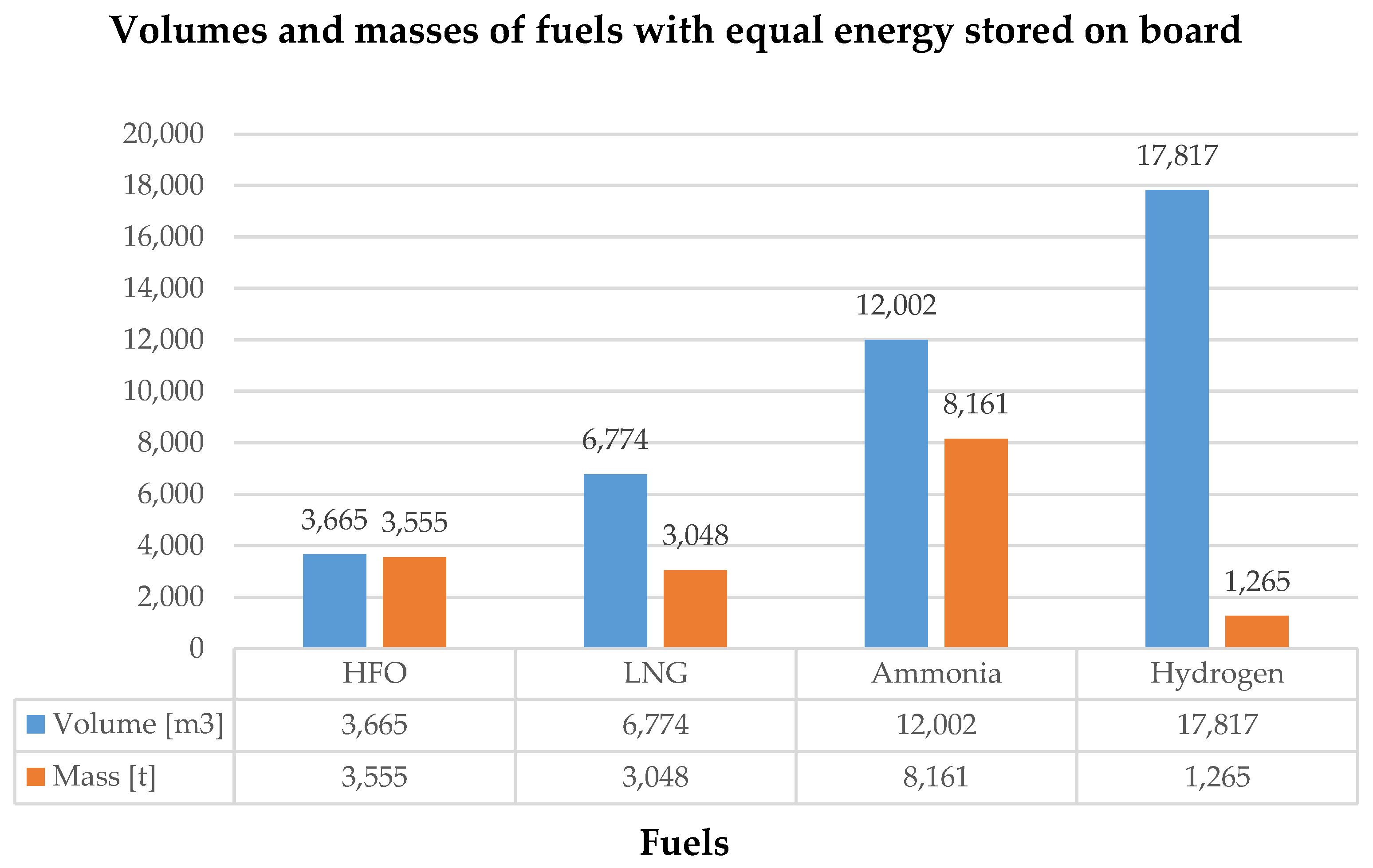
First of all, some considerations regarding the adoption of alternative fuels in place of HFO must be drawn on the basis of their properties. On the basis of the total energy stored on board reported in
Table 3 and equal to 151.8 TJ, the volumes and masses necessary to ensure such an amount of energy were calculated for each fuel considered by exploiting the data presented in
Table 1. The results obtained (
Figure 4) are fundamental for the next steps of the research, as the fuel switch proposed by the authors aims at reducing modifications to the reference ship’s internal layout as much as possible.
At first glance, from
Figure 4, it can be asserted that storing hydrogen in liquid state would be quite impossible without bringing about significant changes that would impact on both the internal space subdivision and the spaces intended for the payload. On the other hand, storing LNG and ammonia in liquid state using dedicated tanks would represent a valid alternative due to the less invasive modifications required. Nevertheless, the space available for the location of such tanks is still limited, therefore, the total capacity of the stored fuel is reduced with respect to HFO. As a result, a reduction in the ship range is an inevitable consequence of the employment of alternative fuels, as will be highlighted in the next sections.
4.1. Storage System for LNG and Ammonia in Liquid State
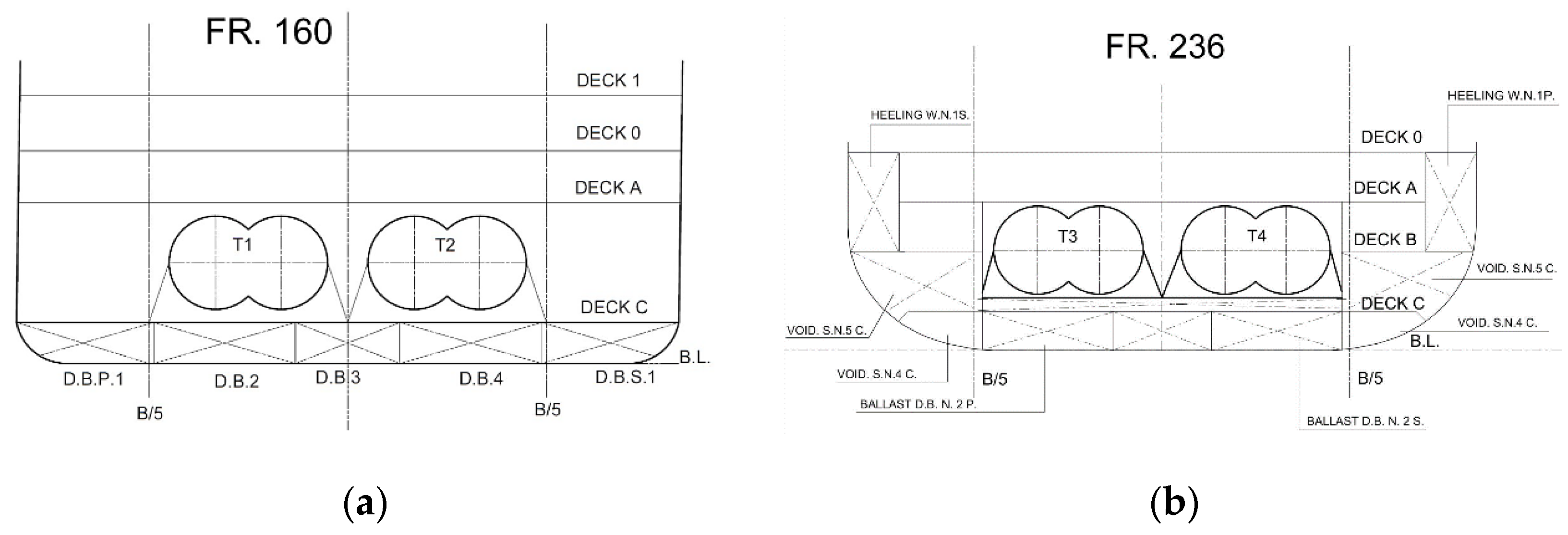
As previously explained, in the reference ship, HFO tanks are located in the ship double bottom. In view of proposing a fuel switch based on LNG or ammonia, such space can be reallocated to substances other than HFO. In particular, due to the necessity of reserving a significant amount of space for LNG/ammonia tanks, the ship double bottom may be used to contain the fresh water supply. Indeed, in the reference ship, this is stored in a dedicated space between Decks C and A. By moving fresh water to the ship double bottom, such space can be emptied to allocate to LNG/ammonia tanks, as shown in
Figure 5 and
Figure 6. Here, four Type-C bilobed tanks can be positioned in full compliancy with the requirements of the IGF Code regarding both distances from the ship’s bottom and sides and areas that may be affected by potential explosions, as provided in
Section 2.
Table 5 shows the main geometric dimensions and properties of the four Type-C bilobed tanks and their onboard longitudinal position. With respect to the selected fuel (i.e., LNG or ammonia), the material used for the construction of the tanks and the thickness of both the walls and the insulating layer will be different, in order to consider the peculiar characteristics of each fuel. However, as an example, for a 20 m long and 5 m tall Type-C bilobed tank, a typical wall thickness without considering the insulating layer is equal to 25 mm [
49].
Two other fundamental characteristics for tanks are the filling limit (FL) and the loading limit (LL). The FL is the maximum allowable liquid volume in the tank, expressed as a percentage of the total tank volume: for LNG at the reference temperature
1, the FL is equal to 98%. The LL is the maximum allowable liquid volume to which the tank may be loaded, expressed as a percentage of the total tank volume. This limit depends on the LNG densities at the loading temperature and reference temperature: typical loading limits for gas-fueled vessels are expected to range from 85 to 95 percent [
50].
For both LNG and ammonia, the loading limit has been considered equal to 85%.
4.2. LNG Scenario
In this first scenario, the six 12V46 DGs currently present in the reference ship are replaced with six dual-fuel DGs having the same main characteristics of the HFO-fueled DGs. Specifically, the dual-fuel DGs maintain the same number of cylinders and bore; consequently, their dimensions, volume, and weight are quite equal to the ones offered by the current DGs, with very slight increases in quantities, as shown in
Table 6. Due to the similar characteristics of the dual-fuel DGs, the changes to be implemented within engine rooms are limited.
The calculation of the consumption of the DGs is based on the efficiencies provided by the manufacturer expressed as a function of the load percentage with respect to the MCR. For the purposes of calculation, a load percentage equal to 76% and the subsequent efficiency of each DG equal to 47.8% were considered. As power input data, the value of the overall electrical load required by the ship at cruise-speed navigation (19.6 kn) with sea margin (25%) was assumed (
Table 4). Furthermore, the consumption of boilers was also added. The results obtained from the calculation are collected in
Table 7.
4.3. Ammonia Scenario
This second scenario is based on the use of ammonia as fuel for internal combustion engines (ICEs). Assuming their dimensions and brake power are comparable with the DGs installed on the reference ships, the main changes will regard auxiliary systems. Indeed, due to the absence of sulfur in ammonia and the low emissions of particulate matter, it is reasonable to assume the removal of the scrubber system, with a consequent advantage in terms of space gain and reduction in related costs. However, in addition to the cracker and the ammonia treatment system, a possible resizing of the SCR plant should be considered. This precaution derives from both the increase in NOx emissions and the release of unburnt ammonia with the consequent production of nitrous oxide (N
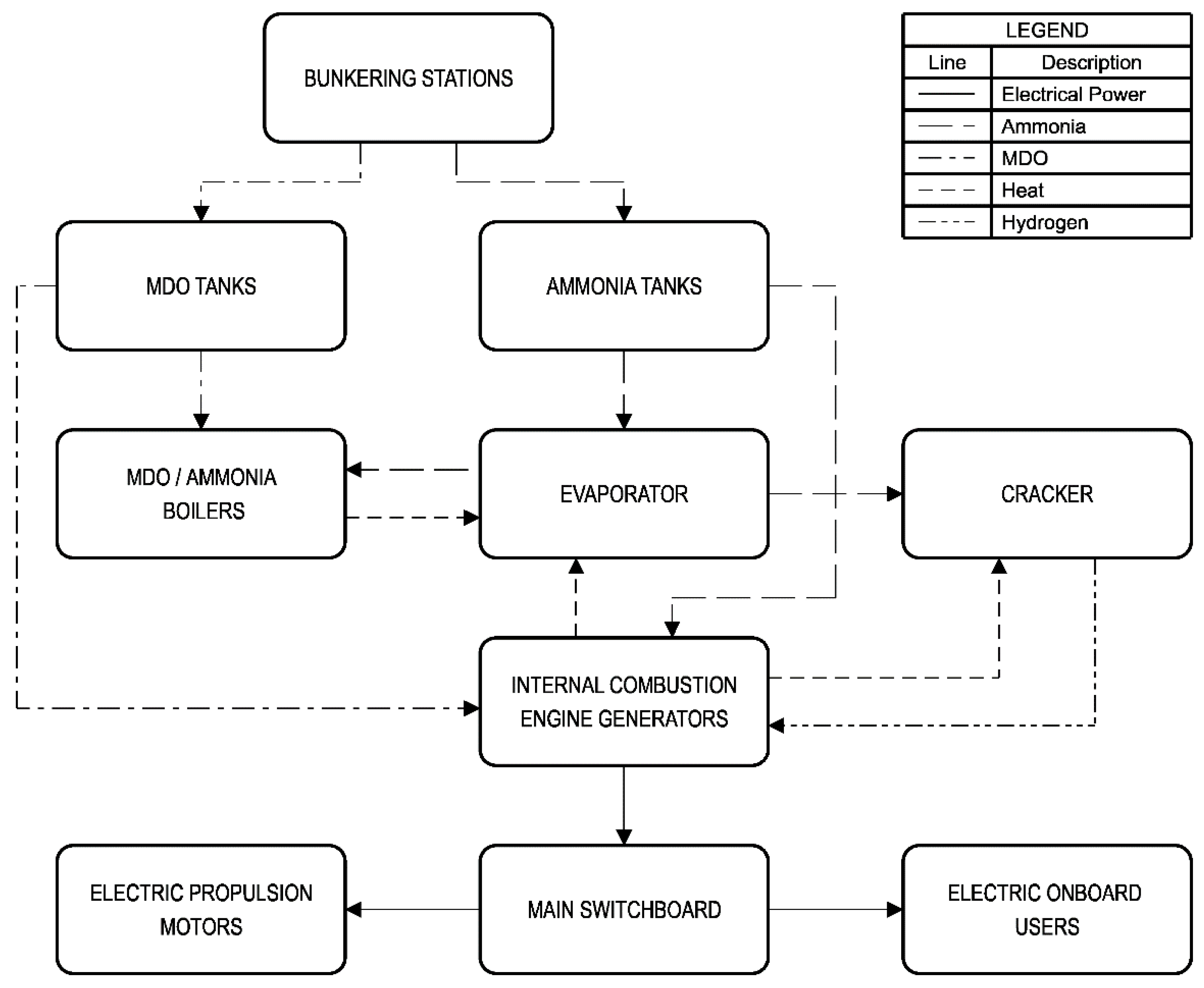
2O). In addition to the above, the installation of a recirculation system for the excess of liquid ammonia coming out of the feed pumps or from the engine itself is envisaged; such a system must also provide for the installation of a device to separate ammonia from any contaminating oils coming from the fuel system. Finally, it is necessary to provide an inert gas system for the ventilation and purification of the engine after operation in dual-fuel mode, for the removal of any remaining gases, and for the pressure seal test of the fuel system. In this system, carbon dioxide or nitrogen can be used. Moreover, the system must be sized in such a way as to provide a sufficient flow of inert gas at a higher pressure than the daily service box. A possible scheme for an ammonia power system is shown in
Figure 7. Here, the tanks for the storage of ammonia in liquid state are visible (as explained in
Section 4.1), as well as the evaporator for the production of hydrogen via cracking (see
Section 2.3 for details).
The calculation of consumption is made assuming an energy efficiency similar to LNG-fueled engines. As reported before, a mixture consisting of 70%vol ammonia and 30%vol hydrogen is considered. It is assumed that the heat of the exhaust gases of the engines is sufficient for the operation of the evaporator and the ammonia cracker, with a consequent increase in the overall efficiency of the system. The results obtained for the whole system considering both DGs and the cracking system are reported in
Table 8.
4.4. Fuel Cell Scenario
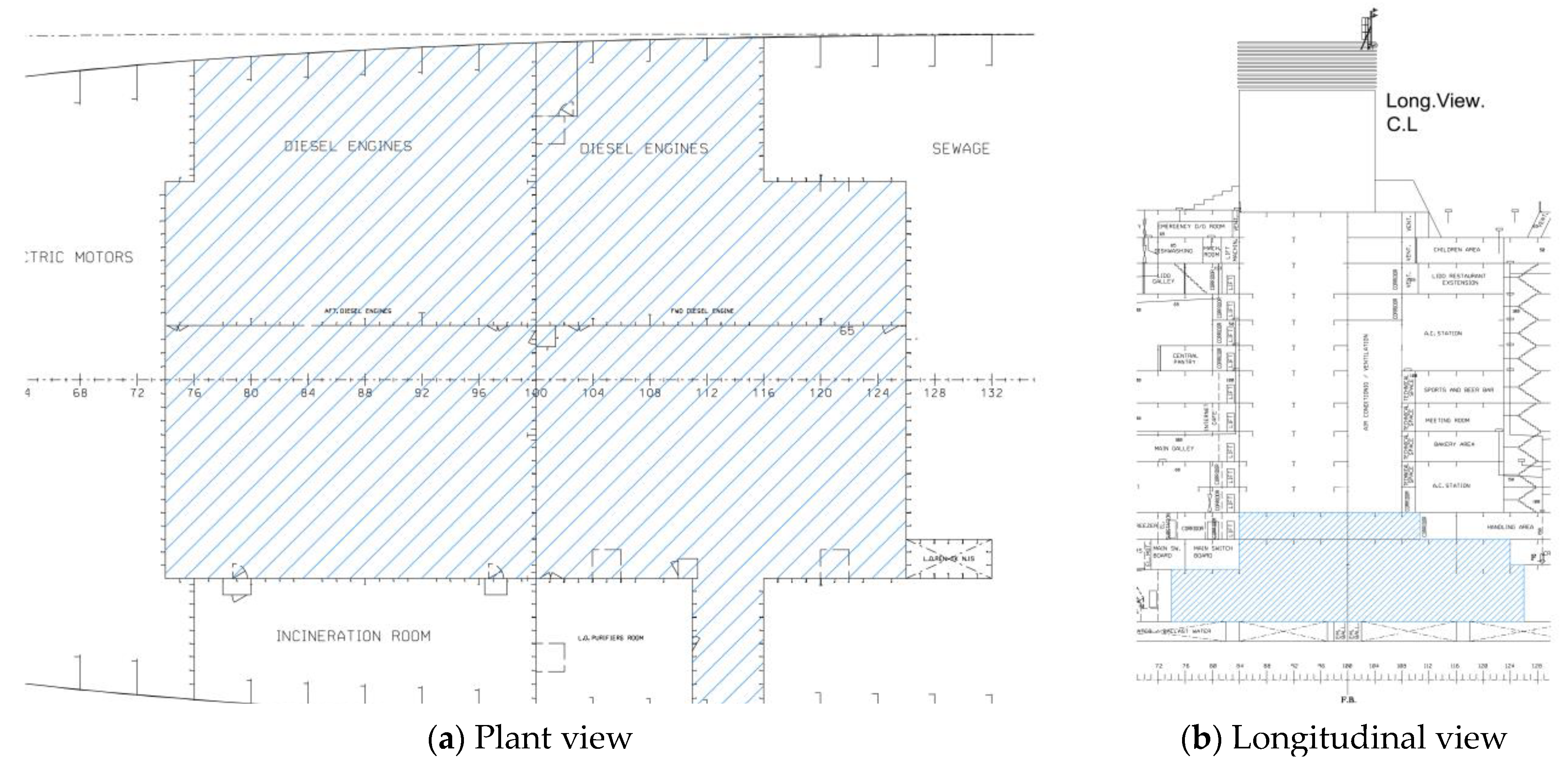
In the third scenario, the assumption is made to remove components related to the current reference ship propulsion system and to equip the ship with fuel cells powered by ammonia/hydrogen and combined with energy accumulation systems. The volume gained from the removal of machinery, equal to almost 5700 m
3, is exploited to allocate fuel cell moduli, fuel treatment and management systems, and batteries (
Figure 8).
4.4.1. Consumption Calculations
For both PEMFCs fueled with hydrogen and SOFCs fueled with either LNG or ammonia, consumption calculations were performed starting from the power required for cruise-speed navigation (40.6 MW,
Table 4) and by taking into account the FC efficiencies, the LCI of the employed fuel, and the consumption of boilers. For PEMFCs, the cracking process to produce hydrogen from ammonia was also considered.
Table 9 and
Table 10 show the results obtained for PEMFCs and SOFCs, respectively.
4.4.2. FC System Layout
Taking as a reference the values of the total power originally installed on the ship and the total electrical load value at cruise speed, for both PEMFCs and SOFCs an equally adequate power could be ensured by adopting fuel cell modules having a nominal power of 50 MW and considering a load factor equal to 85%. As regards the possible dimensions of the fuel cells, the energy densities reported in
Section 2.3 represent reference values. Since these quantities are subject to a large uncertainty depending on the model of the cell, the layout of spaces, and electrical and secondary systems not taken into account, the results obtained are purely indicative. Therefore, considering a fuel cell installed power of 50 MW, different volumes and weights may result depending on the FC types.
In addition, battery modules need to be installed to compensate for load peaks in case of bad weather, maneuvering or in cold start/back-up conditions. Such accumulation systems should be increased for SOFCs, which have a slower response to load variations. The batteries should be enough to cover either the required load in maneuvering reduced by the auxiliary load or the necessary power, in combination with the fuel cells, for navigation at the maximum speed with a 25% sea margin, which means ensuring a power equal to 57.5 MW (
Table 4). Consequently, the estimated energy capacity required for battery modules is equal to 20 MWh. Common lithium-ion batteries have an energy density equal to 260 kWh/t and efficiency that varies from 85 to 90%; as a result, the required powers could be satisfied by 113 t of batteries installed on board (
Table 11).
5. Discussion
In the previous sections, three different alternatives to the conventional propulsion system of the reference ships were presented. For each solution, the authors studied the onboard arrangement and calculated the fuel consumption at the cruise speed of 19.6 knots for a total duration of 17 days of navigation. As a preliminary observation, it is necessary to specify that, for each conversion option discussed, it is plausible to believe that the total power required may be greater due to additional systems related to the analyzed configuration. These loads are difficult to estimate in the initial stages of reasoning and have values of the order of 1 MW. Therefore, for simplicity of analysis, this increase was neglected in the previous calculations.
As explained in
Section 4.1, the same bilobed storage system, having a total capacity of 3812 m
3, was studied for both LNG and ammonia in liquid state. Starting from this value and considering the consumptions calculated for each solution, the days of autonomy and the relative range in nautical miles were estimated, as provided in
Table 12, which also provides data related to the reference configuration (ICE HFO) having 3665 m
3 of fuel stored in double bottom structural tanks. The same outcomes are reported in
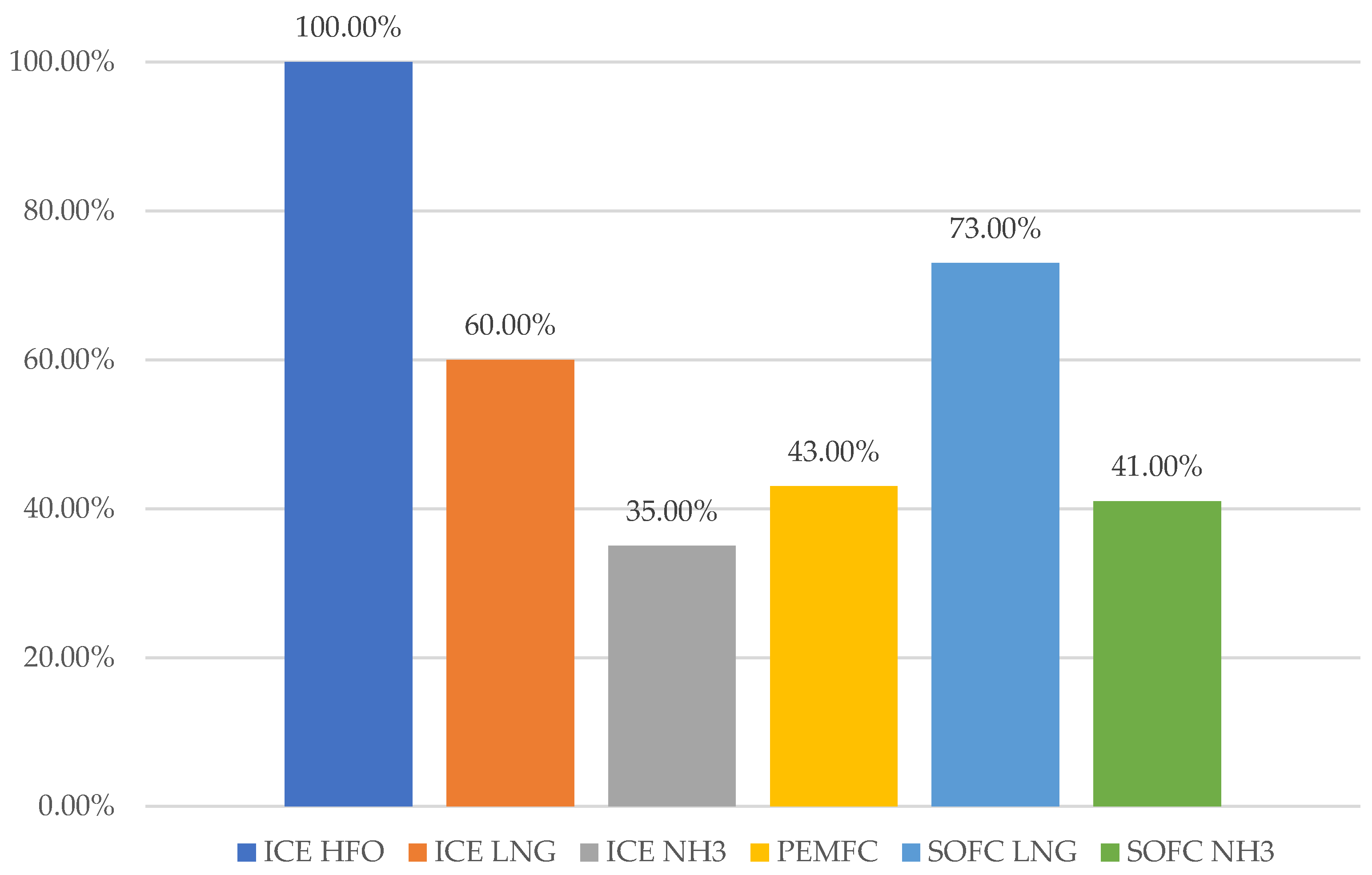
Figure 9 as percentages, assuming the reference ship case as the term of comparison.
Of all the solutions considered in this paper, the conversion to LNG-fueled DGs is, undoubtedly, the most immediate and technologically mature one. Despite being a fossil fuel, natural gas is a cleaner and denser energy carrier. Furthermore, it allows a new consolidated and flexible operation of marine ICEs. In addition, among the fuels considered, it offers the best compromise in terms of volume occupied on board and autonomy as visible from
Table 12 and
Figure 9.
Compared to natural gas, ammonia is a preferable fuel in terms of release of emissions, as it does not contain carbon. In addition, it is less flammable and has more permissive storage conditions in terms of temperature. However, ammonia is highly toxic and extremely harmful to the marine ecosystem. Moreover, ammonia ICEs are subject to an increase in NOx due to the higher quantity of nitrogen and they suffer from the ammonia slip phenomenon. Even though not enough information is available yet as regards ammonia combustion emissions, technologies for the abatement of NOx are now mature and have been commonly used for several years on cruise ships employing traditional fuels. With regard to the release of ammonia, on the other hand, the main engine manufacturers are developing techniques for the optimization of combustion in order to minimize this phenomenon. With reference to autonomy, as shown in
Table 12 and
Figure 9, ammonia-fueled ICEs give the worst values overall but can represent a valuable solution for the production of hydrogen to be employed in PEMFCs and for its use as fuel in SOFCs.
As in the case of ammonia, hydrogen is also a good candidate for use in ICEs and fuel cells, although its storage in liquid form is prohibitive nowadays due to the volume occupied and the storage temperatures close to absolute zero. Nonetheless, due to its excellent energy-carrier properties, its use is more likely in the near future, mainly when stored in the form of ammonia and obtained through the cracking process.
As a final consideration, fuel cells seem to represent a better solution with respect to ICEs (both LNG- and ammonia-fueled) as they offer higher efficiencies. However, it should be considered that many aspects of their actual use and implementation on board are currently unknown. Reference is made to aspects of a technical and operational nature, such as, for example, the response to load variations, operational stability and lifespan in a brackish environment, onboard accommodation, consumption of auxiliary systems such as the cracker, deterioration of components, system maintenance, and safety aspects. Furthermore, fuel cells have not yet reached a level of development that guarantees powers of the order of megawatts unless several modules are used at the same time. Therefore, the entire internal arrangement of a ship would need to be rethought in order to allocate space for not only the storage system for the new fuel, but also the necessary number of fuel cell modules. Such a huge modification could result in a severe reduction in the volume dedicated to the ship payload and a subsequent reduction in shipowner earnings.
The results of the present study might provide useful insights for cruise companies and shipbuilders, who are constantly seeking solutions to move towards greener passenger vessels. In particular, the results might be immediately transferrable for retrofitting an existing vessel. Furthermore, the proposed technical solutions can also be transferred to other vessel types or new designs that offer larger degrees of freedom in terms of main dimensions and general arrangement. For a new build, the range is usually a design requirement, hence, if this will be kept constant by cruise companies, an increase in ship size seems currently mandatory to enable the fuel switch. Moreover, a revision of general arrangement will be required too: more space should be allocated on lower decks for fuel storage systems which can be obtained by moving some technical spaces onto higher decks. For instance, engine room size might be reduced in favor of distributed generation or crew accommodations located below the bulkheads deck might be replaced by auxiliaries or co-generation systems.
6. Conclusions
As the requirements regarding pollutants emitted by ships become stricter day by day, ship designers and shipowners are called to study and implement solutions able to guarantee the necessary reduction in atmospheric emissions. In recent years, several measures have been adopted and are now commonly implemented on board. Indeed, equipment such as heat recovery systems and pollution reduction systems (e.g., scrubbers and SCRs) combined with operational measures such as speed reduction and advanced maintenance are the new norm for ships. However, looking at even more advanced technologies is of paramount importance, since emissions limits are going to exponentially lower in the next few years. As a result, the adoption of both alternative fuels and innovative systems will be mandatory to overcome future challenges. In the present paper, with reference to a medium-sized cruise ship, the authors analyzed three possible technologies able to replace the conventional propulsion system installed on board. ICEs fueled with LNG and ammonia, and fuel cells were studied in depth, and their arrangement and allocation on board was hypothesized.
As pointed out in the previous section, the main challenge in fuel conversion and system updates concerns the necessity of reducing the ship’s autonomy. This transpired to be significantly lowered for each solution considered due to the limited space available for the installation of the LNG/ammonia tanks. With reference to fuel cells, both PEM and SO types seem to have the technological potential to become the main system for generating electricity on board in the near future. However, due to the high demand for power and energy stored on board a large passenger ship, their adoption will not be feasible until their upgrade in technological maturity, which will grant an increased power density and reliability for operations in marine conditions.
To conclude, the present study highlighted that, in the current state of the art, implementing a propulsion conversion of a cruise passenger ship based on the use of alternative fuels and innovative technologies is still not possible without affecting the ship’s autonomy and sacrificing space dedicated to the payload.
Author Contributions
Conceptualization, A.M., I.K. and V.B.; methodology, S.B., I.K. and L.B.; software, I.K., S.B. and L.B.; validation, S.B. and L.B.; formal analysis, S.B., L.B., A.M. and V.B.; investigation, S.B., I.K.; resources, S.B., I.K. and L.B.; data curation, L.B. and S.B.; writing—original draft preparation, S.B., L.B. and V.B.; writing—review and editing, S.B., L.B., A.M. and V.B.; visualization, S.B., I.K. and V.B.; supervision, A.M. and V.B.; project administration, A.M. and V.B.; funding acquisition, A.M. and V.B. All authors have read and agreed to the published version of the manuscript.
Funding
This research received no external funding.
Data Availability Statement
Data sharing is not applicable to this article.
Conflicts of Interest
The authors declare no conflict of interest.
Note
| 1 | The reference temperature is the temperature corresponding to the saturated vapor pressure of the LNG at the set pressure of the pressure relief valves. |
References
- Mudryk, L.R.; Dawson, J.; Howell, S.E.L.; Derksen, C.; Zagon, T.A.; Brady, M. Impact of 1, 2 and 4 °C of Global Warming on Ship Navigation in the Canadian Arctic. Nat. Clim. Chang. 2021, 11, 673–679. [Google Scholar] [CrossRef]
- Brenna, M.; Bucci, V.; Falvo, M.C.; Foiadelli, F.; Ruvio, A.; Sulligoi, G.; Vicenzutti, A. A Review on Energy Efficiency in Three Transportation Sectors: Railways, Electrical Vehicles and Marine. Energies 2020, 13, 2378. [Google Scholar] [CrossRef]
- The 2020 World Merchant Fleet—Statistics from Equasis 2021. Available online: https://www.equasis.org/Fichiers/Statistique/MOA/Documents%20availables%20on%20statistics%20of%20Equasis/Equasis%20Statistics%20-%20The%20world%20fleet%202021.pdf (accessed on 18 October 2022).
- CLIA 2021 Global Market Report 2022. 2022. Available online: https://cruising.org/-/media/clia-media/research/2022/2021-1r-clia-001-overview-global.ashx (accessed on 18 October 2022).
- Cruise Industry Worldwide 2022. Available online: https://www.statista.com/topics/1004/cruise-industry/#topicHeader__wrapper (accessed on 18 October 2022).
- United Nations. Framework Convention on Climate Change Adoption of the Paris Agreement. In Proceedings of the 21st Conference of the Parties, Paris, France, 30 November–12 December 2015; Available online: https://unfccc.int/resource/docs/2015/cop21/eng/l09r01.pdf (accessed on 18 October 2022).
- IMO Resolution MEPC. 304(72) Initial IMO Strategy on Reduction of GHG Emissions from Ships. 2018. Available online: https://wwwcdn.imo.org/localresources/en/KnowledgeCentre/IndexofIMOResolutions/MEPCDocuments/MEPC.304(72).pdf (accessed on 18 October 2022).
- EU. Proposal for a Regulation of the European Parliament and of the Council on the Use of Renewable and Low-Carbon Fuels in Maritime Transport and Amending Directive 2009/16/EC. 2021. Available online: https://eur-lex.europa.eu/legal-content/EN/TXT/?uri=CELEX%3A52021PC0562 (accessed on 18 October 2022).
- Bortuzzo, V.; De Domenico, M.; Bucci, V. Strategies for Ship Decarbonisation: Technical Measure for Reducing Energy Efficiency Existing Ship Index. In Progress in Marine Science and Technology; Rizzuto, E., Ruggiero, V., Eds.; IOS Press: Amsterdam, The Netherlands, 2022; ISBN 978-1-64368-296-9. [Google Scholar]
- Vicenzutti, A.; Sulligoi, G. Electrical and Energy Systems Integration for Maritime Environment-Friendly Transportation. Energies 2021, 14, 7240. [Google Scholar] [CrossRef]
- Yuan, Y.; Wang, J.; Yan, X.; Shen, B.; Long, T. A Review of Multi-Energy Hybrid Power System for Ships. Renew. Sustain. Energy Rev. 2020, 132, 110081. [Google Scholar] [CrossRef]
- Zis, T.P.V. Prospects of Cold Ironing as an Emissions Reduction Option. Transp. Res. Part Policy Pract. 2019, 119, 82–95. [Google Scholar] [CrossRef] [Green Version]
- Braidotti, L.; Mazzarino, M. A Study on Ports’ Emissions in the Adriatic Sea. In Computational Science and Its Applications—ICCSA 2022 Workshops; Gervasi, O., Murgante, B., Misra, S., Rocha, A.M.A.C., Garau, C., Eds.; Lecture Notes in Computer Science; Springer International Publishing: Cham, Switzerland, 2022; Volume 13381, pp. 98–108. ISBN 978-3-031-10547-0. [Google Scholar]
- Bertagna, S.; Braidotti, L.; Bortuzzo, V.; Marinò, A.; Bucci, V. A Fast Feasibility Tool for the Assessment of Fuel Switch in the Concept Design of Merchant Ships. Procedia Comput. Sci. 2022; in press. [Google Scholar]
- Gray, N.; McDonagh, S.; O’Shea, R.; Smyth, B.; Murphy, J.D. Decarbonising Ships, Planes and Trucks: An Analysis of Suitable Low-Carbon Fuels for the Maritime, Aviation and Haulage Sectors. Adv. Appl. Energy 2021, 1, 100008. [Google Scholar] [CrossRef]
- UNCTAD. Review of Maritime Transport 2021. Available online: https://unctad.org/system/files/official-document/rmt2021_en_0.pdf (accessed on 18 October 2022).
- IMO. Fourth IMO GHG Study 2020. Available online: https://www.imo.org/en/OurWork/Environment/Pages/Fourth-IMO-Greenhouse-Gas-Study-2020.aspx (accessed on 18 October 2022).
- International Maritime Organization. Convention for the Prevention of Pollution from Ships (MARPOL)—Annex VI 2020. Available online: https://www.imo.org/en/ourwork/environment/pages/air-pollution.aspx (accessed on 18 October 2022).
- Wilailak, S.; Yoo, B.-H.; Kim, Y.; Lee, C.-J. Parametric Analysis and Design Optimization of Wet SOx Scrubber System in Marine Industry. Fuel 2021, 304, 121369. [Google Scholar] [CrossRef]
- Jang, H.; Jeong, B.; Zhou, P.; Ha, S.; Nam, D.; Kim, J.; Lee, J. Development of Parametric Trend Life Cycle Assessment for Marine SOx Reduction Scrubber Systems. J. Clean. Prod. 2020, 272, 122821. [Google Scholar] [CrossRef]
- Kim, H.-S.; Kasipandi, S.; Kim, J.; Kang, S.-H.; Kim, J.-H.; Ryu, J.-H.; Bae, J.-W. Current Catalyst Technology of Selective Catalytic Reduction (SCR) for NOx Removal in South Korea. Catalysts 2020, 10, 52. [Google Scholar] [CrossRef] [Green Version]
- Zhang, G.; Yan, H.; Li, T.; Zhu, Y.; Zhou, S.; Feng, Y.; Zhou, W. Relation Analysis on Emission Control and Economic Cost of SCR System for Marine Diesels. Sci. Total Environ. 2021, 788, 147856. [Google Scholar] [CrossRef]
- Seddiek, I.S.; Elgohary, M.M. Eco-Friendly Selection of Ship Emissions Reduction Strategies with Emphasis on SOx and NOx Emissions. Int. J. Nav. Archit. Ocean Eng. 2014, 6, 737–748. [Google Scholar] [CrossRef] [Green Version]
- Brynolf, S.; Fridell, E.; Andersson, K. Environmental Assessment of Marine Fuels: Liquefied Natural Gas, Liquefied Biogas, Methanol and Bio-Methanol. J. Clean. Prod. 2014, 74, 86–95. [Google Scholar] [CrossRef]
- Stoumpos, S.; Theotokatos, G.; Boulougouris, E.; Vassalos, D.; Lazakis, I.; Livanos, G. Marine Dual Fuel Engine Modelling and Parametric Investigation of Engine Settings Effect on Performance-Emissions Trade-Offs. Ocean Eng. 2018, 157, 376–386. [Google Scholar] [CrossRef] [Green Version]
- Ammar, N.R. Environmental and cost-effectiveness comparison of dual fuel propulsion options for emissions reduction onboard lng carriers. Brodogradnja 2019, 70, 61–77. [Google Scholar] [CrossRef]
- Grönholm, T.; Mäkelä, T.; Hatakka, J.; Jalkanen, J.-P.; Kuula, J.; Laurila, T.; Laakso, L.; Kukkonen, J. Evaluation of Methane Emissions Originating from LNG Ships Based on the Measurements at a Remote Marine Station. Environ. Sci. Technol. 2021, 55, 13677–13686. [Google Scholar] [CrossRef] [PubMed]
- Peng, Y.; Zhao, X.; Zuo, T.; Wang, W.; Song, X. A Systematic Literature Review on Port LNG Bunkering Station. Transp. Res. Part Transp. Environ. 2021, 91, 102704. [Google Scholar] [CrossRef]
- International Maritime Organization. International Code of Safety for Ship Using Gases or Other Low-Flashpoint Fuels (IGF Code) 2016. Available online: https://www.imo.org/en/ourwork/safety/pages/igf-code.aspx (accessed on 18 October 2022).
- Lindstad, E.; Eskeland, G.S.; Rialland, A.; Valland, A. Decarbonizing Maritime Transport: The Importance of Engine Technology and Regulations for LNG to Serve as a Transition Fuel. Sustainability 2020, 12, 8793. [Google Scholar] [CrossRef]
- Balcombe, P.; Brierley, J.; Lewis, C.; Skatvedt, L.; Speirs, J.; Hawkes, A.; Staffell, I. How to Decarbonise International Shipping: Options for Fuels, Technologies and Policies. Energy Convers. Manag. 2019, 182, 72–88. [Google Scholar] [CrossRef]
- Kim, K.; Roh, G.; Kim, W.; Chun, K. A Preliminary Study on an Alternative Ship Propulsion System Fueled by Ammonia: Environmental and Economic Assessments. J. Mar. Sci. Eng. 2020, 8, 183. [Google Scholar] [CrossRef] [Green Version]
- Al-Breiki, M.; Bicer, Y. Technical Assessment of Liquefied Natural Gas, Ammonia and Methanol for Overseas Energy Transport Based on Energy and Exergy Analyses. Int. J. Hydrogen Energy 2020, 45, 34927–34937. [Google Scholar] [CrossRef]
- Abohamzeh, E.; Salehi, F.; Sheikholeslami, M.; Abbassi, R.; Khan, F. Review of Hydrogen Safety during Storage, Transmission, and Applications Processes. J. Loss Prev. Process Ind. 2021, 72, 104569. [Google Scholar] [CrossRef]
- Taccani, R.; Malabotti, S.; Dall’Armi, C.; Micheli, D. High Energy Density Storage of Gaseous Marine Fuels: An Innovative Concept and Its Application to a Hydrogen Powered Ferry. Int. Shipbuild. Prog. 2020, 67, 33–56. [Google Scholar] [CrossRef]
- Wang, Y.; Zhou, X.; Liu, L. Theoretical Investigation of the Combustion Performance of Ammonia/Hydrogen Mixtures on a Marine Diesel Engine. Int. J. Hydrogen Energy 2021, 46, 14805–14812. [Google Scholar] [CrossRef]
- Mørch, C.S.; Bjerre, A.; Gøttrup, M.P.; Sorenson, S.C.; Schramm, J. Ammonia/Hydrogen Mixtures in an SI-Engine: Engine Performance and Analysis of a Proposed Fuel System. Fuel 2011, 90, 854–864. [Google Scholar] [CrossRef]
- de Vries, N. Safe and Effective Application of Ammonia as a Marine Fuel. TU Delft—Delft University of Technology, 2019. Available online: https://repository.tudelft.nl/islandora/object/uuid%3Abe8cbe0a-28ec-4bd9-8ad0-648de04649b8 (accessed on 18 October 2022).
- Dall’Armi, C.; Micheli, D.; Taccani, R. Comparison of Different Plant Layouts and Fuel Storage Solutions for Fuel Cells Utilization on a Small Ferry. Int. J. Hydrogen Energy 2021, 46, 13878–13897. [Google Scholar] [CrossRef]
- Inal, O.B.; Charpentier, J.-F.; Deniz, C. Hybrid Power and Propulsion Systems for Ships: Current Status and Future Challenges. Renew. Sustain. Energy Rev. 2022, 156, 111965. [Google Scholar] [CrossRef]
- Braidotti, L.; Bertagna, S.; Marino, A.; Bosich, D.; Bucci, V.; Sulligoi, G. An Application of Modular Design in the Refitting of a Hybrid-Electric Propelled Training Ship. In Proceedings of the 2020 AEIT International Annual Conference (AEIT), Catania, Italy, 23–25 September 2020; pp. 1–6. [Google Scholar]
- Degan, G.; Braidotti, L.; Bosich, D.; Sulligoi, G.; Bucci, V.; Marino, A. Feasibility Study of a DC Hybrid-Electric Catamaran for River Navigation. In Proceedings of the 2021 Sixteenth International Conference on Ecological Vehicles and Renewable Energies (EVER), Monte-Carlo, Monaco, 5–7 May 2021; pp. 1–5. [Google Scholar]
- Chua, K.H.; Lih Bong, H.; Lim, Y.S.; Wong, J.; Wang, L. The State-of-the-Arts of Peak Shaving Technologies: A Review. In Proceedings of the 2020 International Conference on Smart Grid and Clean Energy Technologies (ICSGCE), Kuching, Malaysia, 4–7 October 2020; pp. 162–166. [Google Scholar]
- Gianni, M.; Pietra, A.; Taccani, R. Outlook of Future Implementation of PEMFC and SOFC Onboard Cruise Ships. E3S Web Conf. 2021, 238, 04004. [Google Scholar] [CrossRef]
- Peighambardoust, S.J.; Rowshanzamir, S.; Amjadi, M. Review of the Proton Exchange Membranes for Fuel Cell Applications. Int. J. Hydrogen Energy 2010, 35, 9349–9384. [Google Scholar] [CrossRef]
- van Biert, L.; Godjevac, M.; Visser, K.; Aravind, P.V. A Review of Fuel Cell Systems for Maritime Applications. J. Power Sources 2016, 327, 345–364. [Google Scholar] [CrossRef] [Green Version]
- Di Micco, S.; Minutillo, M.; Mastropasqua, L.; Cigolotti, V.; Brouwer, J. Ammonia-Based Solid Oxide Fuel Cell for Zero Emission Maritime Power: A Case Study. E3S Web Conf. 2022, 334, 06007. [Google Scholar] [CrossRef]
- Ghirardo, F.; Santin, M.; Traverso, A.; Massardo, A. Heat Recovery Options for Onboard Fuel Cell Systems. Int. J. Hydrogen Energy 2011, 36, 8134–8142. [Google Scholar] [CrossRef]
- Yao, Y.; Guo, Z.; Duan, M.; Zhou, L.; Liu, B. The Structure Design of Type-C Independent Tank on LNG Ship; Techno-Press: Incheon, Korea, 25–29 August 2015; p. 10. [Google Scholar]
- American Bureau of Shipping. LNG Bunkering Technical and Operational Advisory 2021. Available online: https://ww2.eagle.org/content/dam/eagle/advisories-and-debriefs/ABS_LNG_Bunkering_Advisory.pdf (accessed on 18 October 2022).
Figure 1.
Comparison between fuels in terms of LCV and volumetric energy density.
Figure 1.
Comparison between fuels in terms of LCV and volumetric energy density.
Figure 2.
Profile view of the reference ship.
Figure 2.
Profile view of the reference ship.
Figure 3.
Shipboard power system layout.
Figure 3.
Shipboard power system layout.
Figure 4.
Comparison between fuels in terms of volumes and masses with equal energy stored on board.
Figure 4.
Comparison between fuels in terms of volumes and masses with equal energy stored on board.
Figure 5.
Type-C bilobed tanks’ location: (a) Section at frame 160; (b) Section at frame 236.
Figure 5.
Type-C bilobed tanks’ location: (a) Section at frame 160; (b) Section at frame 236.
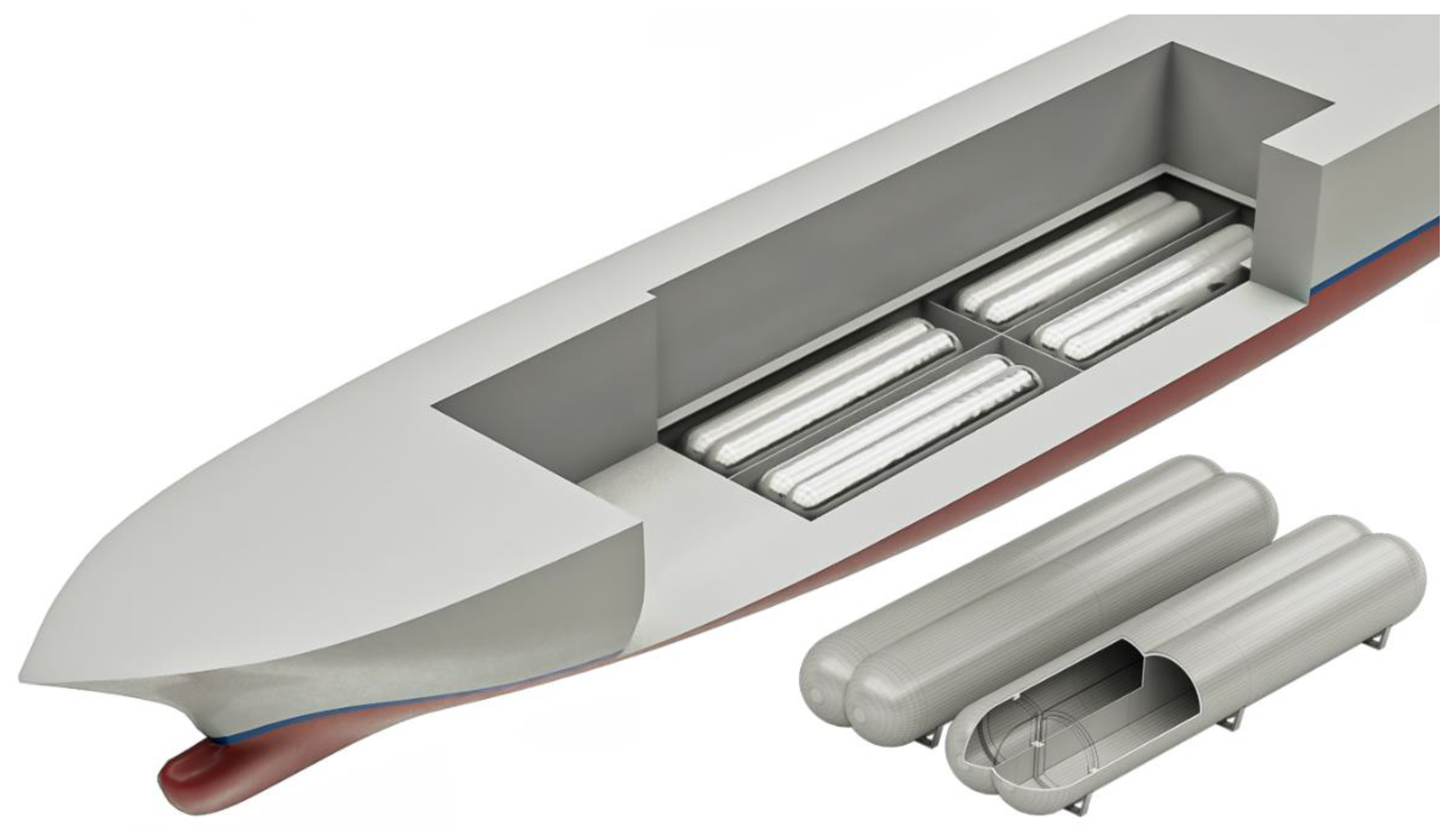
Figure 6.
Type-C bilobed tanks location: 3D rendering.
Figure 6.
Type-C bilobed tanks location: 3D rendering.
Figure 7.
Ammonia power system scheme.
Figure 7.
Ammonia power system scheme.
Figure 8.
Spaces for the allocation of the fuel cell moduli, the fuel system, and batteries.
Figure 8.
Spaces for the allocation of the fuel cell moduli, the fuel system, and batteries.
Figure 9.
Comparison in percentage between autonomies for the different propulsion solutions.
Figure 9.
Comparison in percentage between autonomies for the different propulsion solutions.
Table 1.
Comparison between fuels [
15].
Table 1.
Comparison between fuels [
15].
| Fuel | Lower Calorific Value (LCV) | Density | Volumetric Energy
Density | Storage
Pressure | Storage
Temperature | Volumetric
Factor_HFO |
|---|
| - | [MJ/kg] | [t/m3] | [MJ/m3] | [bar] | [°C] | - |
| HFO | 42.70 | 0.97 | 41,419 | 1.0 | 50 | 1.0 |
| MDO | 44.00 | 0.87 | 38,280 | 1.0 | 20 | 0.9 |
| LNG | 49.80 | 0.45 | 22,410 | 1.0 | −163 | 1.8 |
| AMM 1 | 18.60 | 0.68 | 12,648 | 1.0 | −33 | 3.3 |
| HYD 2 | 120.0 | 0.07 | 8520 | 1.0 | −253 | 4.9 |
Table 2.
Main characteristics of the reference ship.
Table 2.
Main characteristics of the reference ship.
| Length overall | LOA | 290 m |
| Breadth | B | 35.5 m |
| Construction height | D | 70 m |
| Draught | T | 8.2 m |
| Gross tonnage | GT | 112,000 gt |
| Passengers | - | 3780 |
| Crew | - | 1500 |
| Cruise speed | Vcruise | 19.6 kn |
| Maximum speed | Vmax | 23.2 kn |
| Range | m | 8000 nm |
| Autonomy | d | 17 days |
| Total installed power | Ptot | 75.6 MW |
| Alternator efficiency | ηAlt | 0.97 |
| Total electric power | Pelec_tot | 73.3 MW |
| Propulsion power | Pprop | 42 MW |
Table 3.
Total amount of energy stored on board the reference ship.
Table 3.
Total amount of energy stored on board the reference ship.
| Fuel | Volume [m3] | Density [t/m3] | LCV [MJ/kg] | Energy Stored [TJ] |
|---|
| HFO | 3665 | 0.97 | 42.70 | 151.8 |
Table 4.
Power required and DG load factors for the reference ship in different conditions.
Table 4.
Power required and DG load factors for the reference ship in different conditions.
| | Cruise-Speed
Navigation | Max-Speed Navigation | Maneuvering | Hoteling at Berth |
|---|
| Power required |
| Services | P [MW] | P [MW] | P [MW] | P [MW] |
| Propulsion and Maneuvering 1 | 22 | 34 | 14.82 | / |
| Hull and Machinery Services 2 | 1.25 | 1.25 | 1.25 | 1.25 |
| Main Systems 3 | 0.5 | 0.5 | 0.3 | 0.4 |
| Other Services 4 | 0.05 | 0.05 | 0.05 | 0.05 |
| HVAC 5 | 6.0 | 7.5 | 6.0 | 6.0 |
| Accommodations 6 | 1.4 | 1.4 | 1.4 | 1.4 |
| Communication and Navigation 7 | 0.1 | 0.1 | 0.1 | 0.05 |
| Lighting 8 | 1.2 | 1.2 | 1.2 | 1.2 |
| Total | 32.5 | 46 | 25.1 | 10.4 |
| Total with SM | 40.6 | 57.5 | / | / |
| DG load factors |
| Number of DGs required | 4 | 6 | 4 | 2 |
| Available electric power at MCR | 48.9 MW | 73.3 | 48.9 | 24.4 |
| Load factor | 0.83 | 0.78 | 0.51 | 0.43 |
Table 5.
Geometric properties and positions of the Type-C bilobed tanks selected.
Table 5.
Geometric properties and positions of the Type-C bilobed tanks selected.
| Tank | Code | Frame Aft | Frame Fore | L [m] | B [m] | H [m] | V [m3] |
|---|
| Tank 1 | TK.1P | 144 | 194 | 36 | 8.5 | 5.0 | 953 |
| Tank 2 | TK.1S | 144 | 194 | 36 | 8.5 | 5.0 | 953 |
| Tank 3 | TK.2P | 201 | 251 | 36 | 8.5 | 5.0 | 953 |
| Tank 4 | TK.2S | 201 | 251 | 36 | 8.5 | 5.0 | 953 |
| Total volume stored on board | 3812 |
Table 6.
Properties of both the HFO and the dual-fuel DGs.
Table 6.
Properties of both the HFO and the dual-fuel DGs.
| Engine | Cylinder | Bore | L | B | H | W | V | PB | rpm |
|---|
| - | - | [cm] | [mm] | [mm] | [mm] | [t] | [m3] | [kW] | - |
|---|
| HFO | 12 | 46 | 10.26 | 4.530 | 5.16 | 169 | 240 | 12.60 | 514 |
| Dual-fuel | 12 | 46 | 10.38 | 4.555 | 5.29 | 184 | 268 | 13.74 | 600 |
Table 7.
Consumption calculations for dual-fuel DGs at cruise speed.
Table 7.
Consumption calculations for dual-fuel DGs at cruise speed.
| | DGs | Boiler |
|---|
| Number of DGs required | 4 | |
| Available electric power at MCR [MW] | 53.3 | |
| Load factor | 0.76 | |
| Efficiency | 0.478 | - |
| LNG consumption [kg/s] | 1.70 | - |
| LNG consumption [t/day] | 146.9 | 16.3 |
| Total LNG weight for 17-day navigation [t] | 2775 |
| Total LNG volume for 17-day navigation [m3] | 6166 |
Table 8.
Consumption calculations for ammonia-fueled power system.
Table 8.
Consumption calculations for ammonia-fueled power system.
| | Ammonia | Hydrogen |
|---|
| Efficiency | 0.493 |
| System consumption [kg/s] | 3.48 | 0.98 |
| Boiler consumption [t/day] | 43.7 | - |
| Ammonia consumption [t/day] | 429 | - |
| Total ammonia weight for 17-day navigation [t] | 7298 |
| Total ammonia volume for 17-day navigation [m3] | 10,732 |
Table 9.
Consumption calculations for hydrogen-fueled PEMFCs.
Table 9.
Consumption calculations for hydrogen-fueled PEMFCs.
| | PEMFC | Cracker | Boiler |
|---|
| Efficiency | 0.55 | 0.63 | - |
| Ammonia consumption [kg/s] | 0.62 | 3.49 | - |
| Ammonia consumption [t/day] | 346 | 302 | 43.7 |
| Total ammonia weight for 17-day navigation [t] | 5874 |
| Total ammonia volume for 17-day navigation [m3] | 8638 |
Table 10.
Consumption calculations for LNG- or ammonia-fueled SOFCs.
Table 10.
Consumption calculations for LNG- or ammonia-fueled SOFCs.
| | LNG | Ammonia |
|---|
| Efficiency | 0.60 |
| SOFC consumption [kg/s] | 1.37 | 3.67 |
| Boiler consumption [kg/s] | 0.19 | 0.51 |
| Total consumption [kg/s] | 1.56 | 4.18 |
| Daily consumption [t/day] | 134.7 | 360.7 |
| Total fuel weight for 17-day navigation [t] | 2290 | 6132 |
| Total fuel volume for 17-day navigation [m3] | 5090 | 9018 |
Table 11.
Properties of the battery modules.
Table 11.
Properties of the battery modules.
| Energy Required | Energy Density | Efficiency | Discharge Percentage | Modules |
|---|
| MWh | MJ | kWh/t | MWh/m3 | - | % | t | m3 |
|---|
| 20 | 72,000 | 260 | 0.70 | 0.85 | 80 | 113 | 40 |
Table 12.
Comparison of autonomies and ranges for each propulsion alternative at cruise speed.
Table 12.
Comparison of autonomies and ranges for each propulsion alternative at cruise speed.
| Solution | Fuel Embarked | Autonomy | Range |
|---|
| - | [m3] | [days] | [nm] |
|---|
| ICE HFO | 3665 | 17.5 | 8224 |
| ICE LNG | 3812 | 10.5 | 4945 |
| ICE NH3 | 3812 | 6.0 | 2841 |
| PEMFC | 3812 | 7.5 | 3530 |
| SOFC LNG | 3812 | 12.7 | 5990 |
| SOFC NH3 | 3812 | 7.2 | 3381 |
| Disclaimer/Publisher’s Note: The statements, opinions and data contained in all publications are solely those of the individual author(s) and contributor(s) and not of MDPI and/or the editor(s). MDPI and/or the editor(s) disclaim responsibility for any injury to people or property resulting from any ideas, methods, instructions or products referred to in the content. |
© 2023 by the authors. Licensee MDPI, Basel, Switzerland. This article is an open access article distributed under the terms and conditions of the Creative Commons Attribution (CC BY) license (https://creativecommons.org/licenses/by/4.0/).


