Article

Experimental Study of Supercavitation Bubble Development over Bodies in a Free-Surface Flow

Faculty of Aerospace Engineering, Technion–Israel Institute of Technology, Haifa 32000, Israel
*
Author to whom correspondence should be addressed.
J. Mar. Sci. Eng. 2022, 10(9), 1244; https://doi.org/10.3390/jmse10091244
Submission received: 13 July 2022 / Revised: 16 August 2022 / Accepted: 28 August 2022 / Published: 4 September 2022
(This article belongs to the Topic Latest Developments in Fluid Mechanics and Energy)

Abstract

:
This research conducts experimental studies on supercavitation bubble development and characteristics within free-surface water and the role of cavitator, comparing the results to those of similar experiments carried on in a duct flow. Tests have been conducted on cylindrical bodies (47 mm diameter) moving underwater at different velocities in a 10-m-diameter circular pool of about 50 cm water level. A comparison has been made for supercavitation bubbles resulting from six different cavitator geometries (flat, sphere, cone, ogive, inverted sphere, and truncated cone). The comparison referred to the conditions of the bubble formation, as well as to the shape and development. It was found that the different cavitators produced different bubble geometries as opposed to the results of experiments conducted in a duct flow by the authors. Nevertheless, the order of onset of cavitation bubble creation (with relation to the cavitation number and flow velocity) was similar. One of the conclusions of this study was that the pressure difference used for defining the cavitation number has a significant impact on the correlation between the bubble characteristics and cavitation number. This fact should be considered when comparing data from different sources.

1. Introduction

Studies on the formation and development of supercavitation bubbles have been the subject of both theoretical and experimental investigations, promoting the scientific as well as the practical aspects related to supercavitation vessels. Logvinovich [1], Serebriakov [1,2,3], Semenenco [4], and Savchenco [5] focused mainly on calculating axisymmetric bubbles and their relation to flow conditions. Wall effect and also cavitation number influence on the bubble shape have been considered as well [6]. Natural and artificial (ventilated) supercavitation bubble development in bounded and unbounded flows have been investigated experimentally [7,8]. The bounded case is important with relation to flows in machine devices such as pumps, where the appearance of cavitation reduces the efficiency. The cavitator shape plays a significant role in determining the bubble formation and characteristics. Analytical and numerical studies have been conducted for two- and three-dimensional flows for certain geometries in [9,10], respectively, whereas the effect of cavitator on bubble dimensions was shown in [11]. Prediction for unbounded bubbles has been the subject of a number of research programs [12,13,14,15,16,17,18]. Others conducted experimental studied on flow separation, bubble closing, and gravitation effects. In their monograph, Frank and Michel [19] displayed the major aspects related to the fundamentals of cavitation. An investigation of supercavitation bubbles development and formation was made by these authors [20] for a duct (bounded) flow, comparing different cavitators (e.g., flat, spherical, and conical) with respect to flow conditions for bubble creation, development, shape, and collapse. For such bounded flow conditions, it was found that all cavitators produced supercavitation bubbles of a similar shape, though at different flow speeds, where the flat nose cavitator implied onset of cavitation at the lowest flow speed, then the spherical, and last (at the highest flow speed) the conical.
The present study has investigated experimentally supercavitation bubble development over cylindrical bodies moving underwater in a pool having free unbounded surface. The effect of cavitators of six different geometries on the onset, development, and dimensions of the bubble formed was studied with relation to the cavitation number and flow speed. The results were compared to those found in a duct flow.
The dimensionless cavitation number is one of the parameters characterizing the supercavitational flow. Its magnitude gives a significant indication about the cavitation intensity [21]. Different ways of calculating this number have been suggested in researches, offering approaches to describe the physical system and predict the development of the supercavitational flow [19]. The cavitation number became a basic factor to characterize the system and to examine the corresponding dimensions and development of the supercavitation bubble. In this research, we present the influence of the way of calculating the cavitation number on the resulting bubbles, revealing that it should be accounted for when examining supercavitation results from different sources.
Regarding the experimental aspect, typical systems for research and development of underwater supercavitational vehicles are either complex, energy consuming, and of costly maintenance (e.g., large, high-speed water tunnels), or they are more accurate but too small for predicting actual vehicle characteristics. In the present paper, we use a pioneering, simply designed, easy to maintain experimental system having as well relatively low operating energy demands. The system enables investigating fair-size bodies, characterizing and demonstrating phenomena that can be related to real-size vehicles.

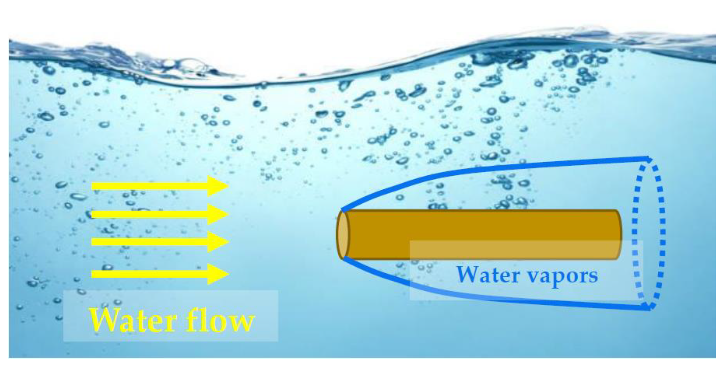
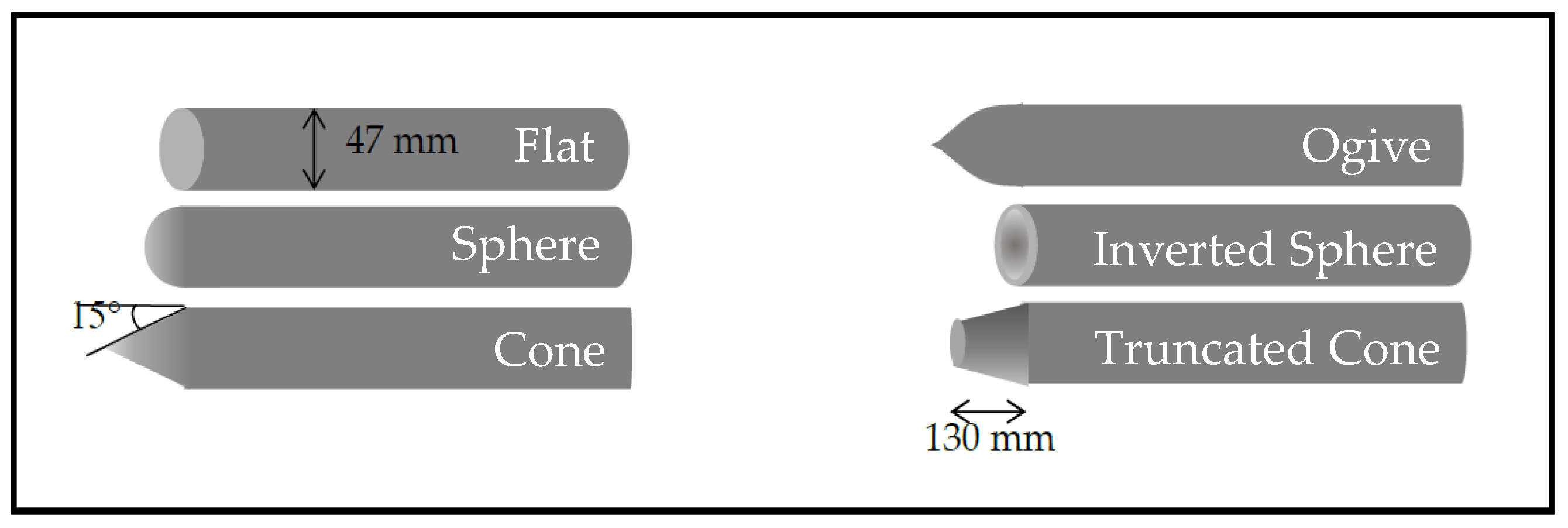
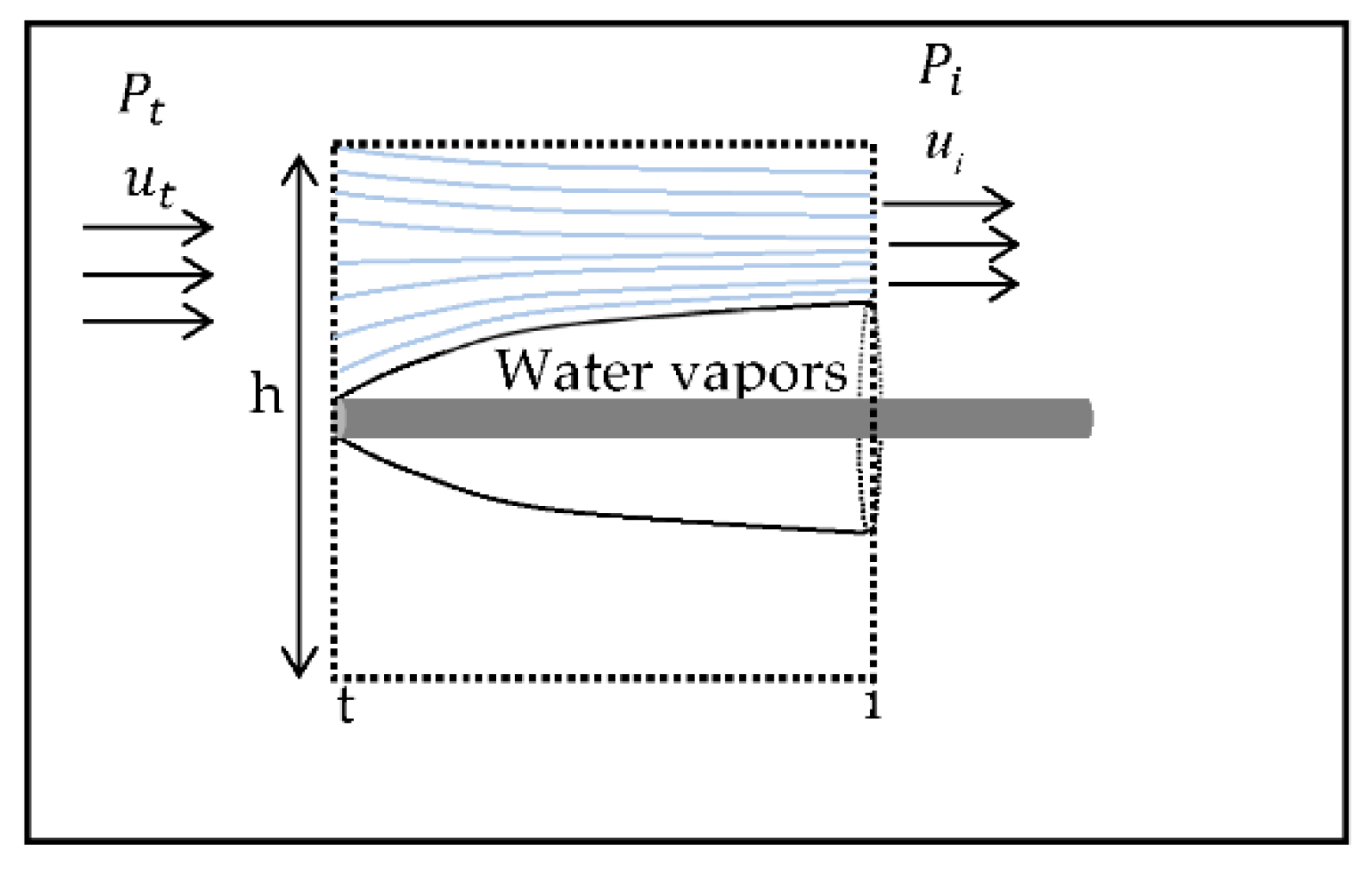
2. Problem Description

In this research, the development of supercavitation bubbles over axisymmetric cylindrical bodies moving underwater in a pool with a free surface has been investigated. The cavitation bubble forms due to the front edge cavitator (nose), causing change of water flow-field, flow separation, and pressure drop. When the pressure attains values below the equilibrium vapor pressure, evaporation of water (cavitation) occurs. Increasing the water flow velocity, the zone of reduced pressure extends, and the bubble grows until enveloping the entire body (Figure 1). The shape of the cavitator plays an important role in the bubble formation and development.

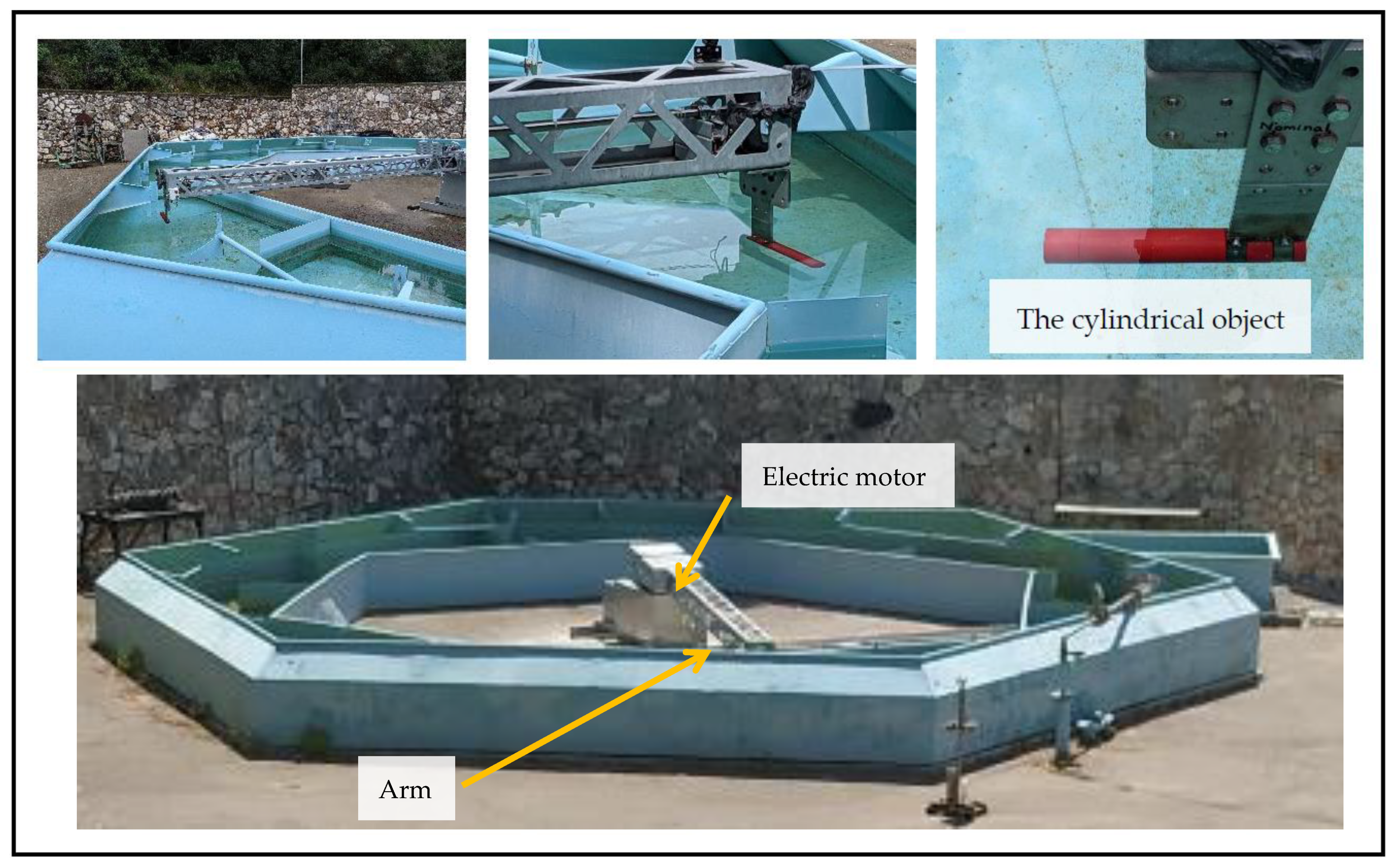
3. The Experimental System and Flow Conditions

The experimental system consists of a water pool with a depth of about 50–60 cm built from two hexagons. The outer hexagons with a radius of 5.2 m and inner hexagon with a radius of 4.3 m are diverted to one another to reduce the rotation of the water during the circular motion in the pool. An arm of 4.82 m length is connected to an Oemer electric motor of maximum power of 31 kW, with 1:28 Sumitomo transmission. The arm can hold bodies weighing a few kg and move them in the water with a velocity of up to 25 m/s (see Figure 2) in a 30 m circumference. The electric motor is controlled by an Emerson M700 controller. It communicates with a PC at a rate of 100 Hz via a National Instrument analog-to-digital device. The data displayed online include motor rpm and moment as well as motion speed, which can be controlled and changed in real time. A Go-Pro camera placed at the bottom of the pool or at the arm above the examined object provides pictures of the bobble formation and shape. A safety button is placed at the operator post. When pushed by the operator (in case malfunction or emergency), the power supply to the electric motor as well as the overall operation stop immediately.
The objects examined were held by the arm and were accelerated in the pool to the desired speeds. Six slender cylindrical bodies of 47 ± 0.1 mm diameter and 280 ± 1 mm length (aspect ratio of about 6) of the cylindrical section with different cavitators (noses) have been tested: a flat cavitator, a spherical cavitator, a conical cavitator with an angle of 15°, a cavitator of a truncated cone of 130 ± 0.5 mm height, a cavitator of an inverted sphere, and an ogive cavitator (see Figure 3). The bubble created over the bodies was examined for different speeds. In the range tested, the body’s length was much larger than the bubbles formed; hence, the aspect ratio had no impact on the results. The large distance between the channel side walls (over 1000 mm) as well as the location of the examined (47 mm diameter) bodies at about the midway between the free upper surface and the bottom (total of about 500 mm) were assumed to have no or only minimal effect on the flow around the submerged bodies.

4. Results

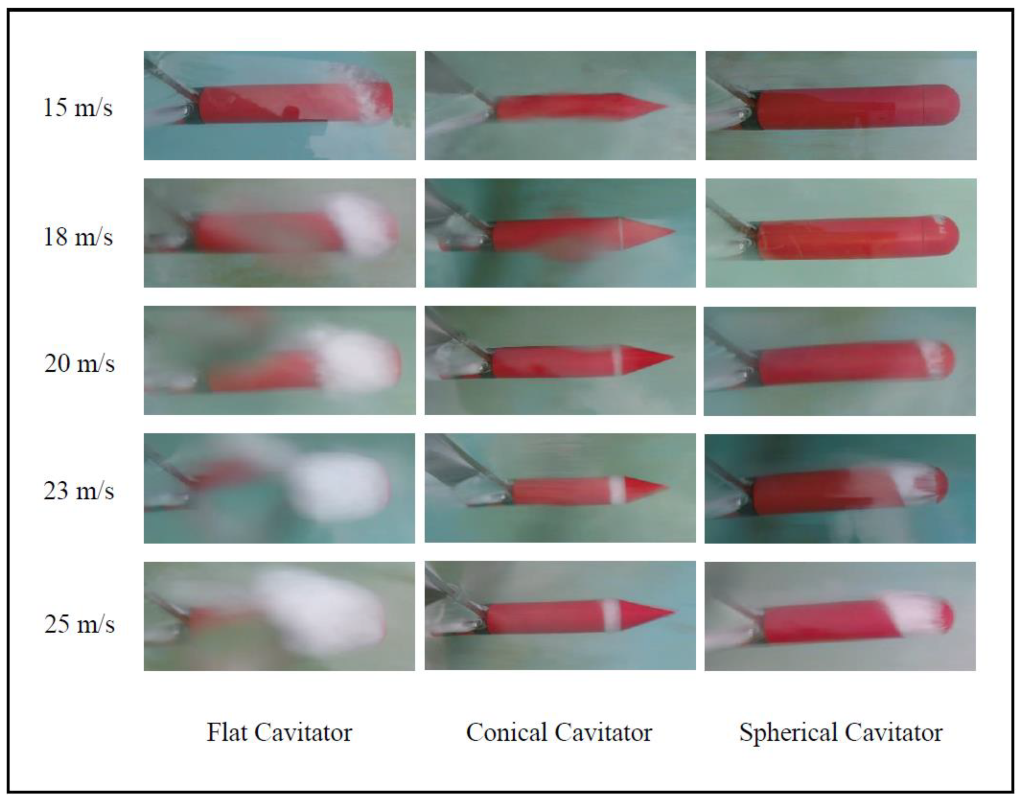
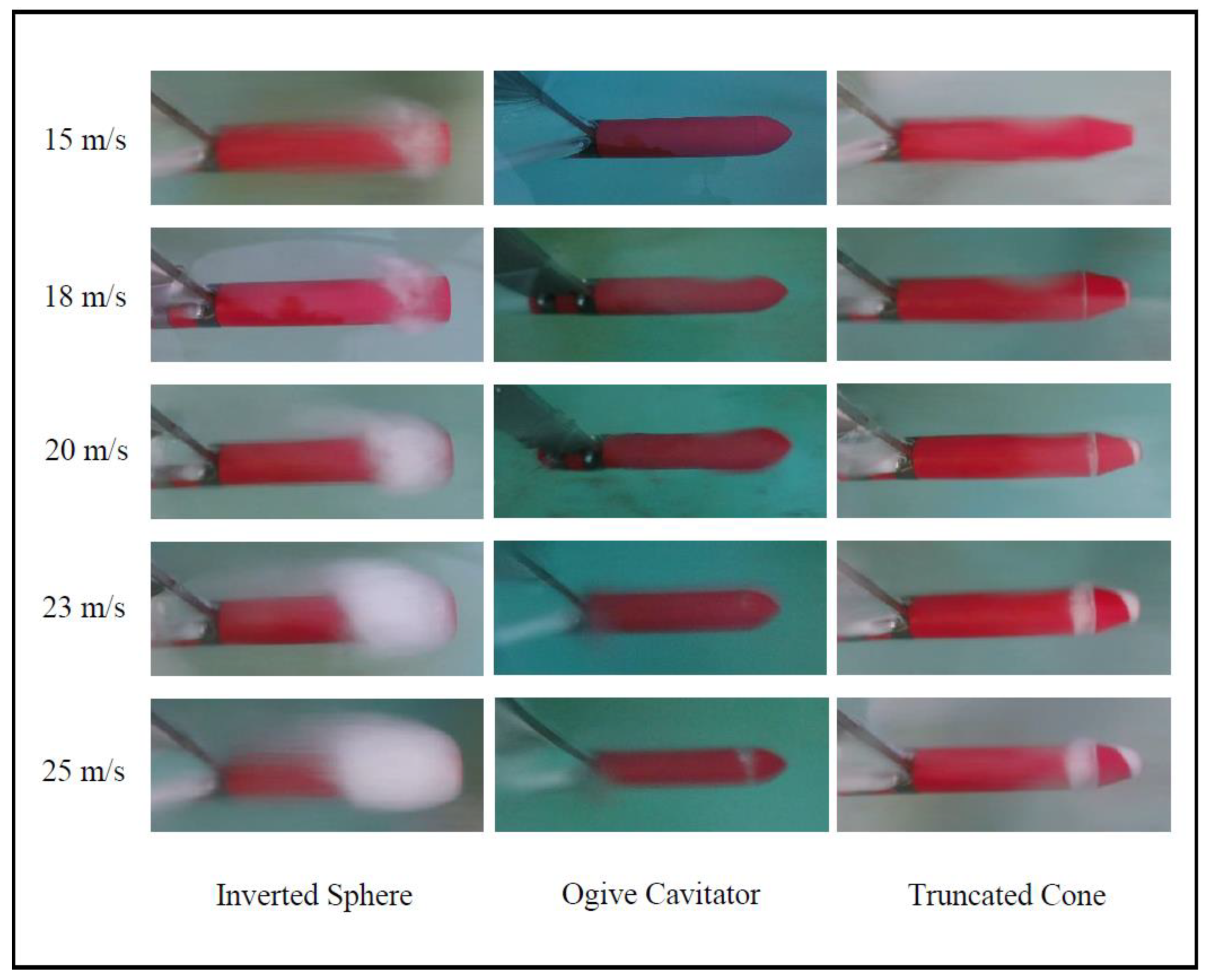
4.1. Stages of Bubble Development

The different stages in the bubble development along the body with increasing the flow velocity (motion speed) are presented in Figure 4 and Figure 5 for all six different cavitators. The observed geometries of the bubbles were different for each of the six different cavitators, as opposed to the results in a duct flow, where practically similar bubbles were obtained for the different cavitators [20]. The bubbles did not close on the body at any stage of the flow, and they remained open in their back edge, similarly to the results of a duct flow. The correlation of the bubble geometry to standard functions no longer holds in free-surface conditions, and each cavitator causes a different flow regime leading to a different bubble geometry.
We would like to present here a known expression for a supercavitation bubble shape, which was used by Semenenko (2001) [3] based on Logvinovich’s empirical results (1973) [16]:
f a = d 2 ( 1 + 6 d z ) 1 3
where d is the cavitator diameter, and z is the axial distance along the body expressed with the same length units as d.
We have figured out that Equation (1) could express the bubble shape for free-surface flow only at sufficiently high flow velocities. It is in contrast to bubbles in a duct flow, which could be described by this function at low speeds only. No other functions describing bubbles in both free-surface flows and duct flows have been found.
The cavitators of a less hydrodynamic shape impose a larger disturbance on the flow, causing the onset of cavitation at a lower speed, as well as a larger final bubble size.

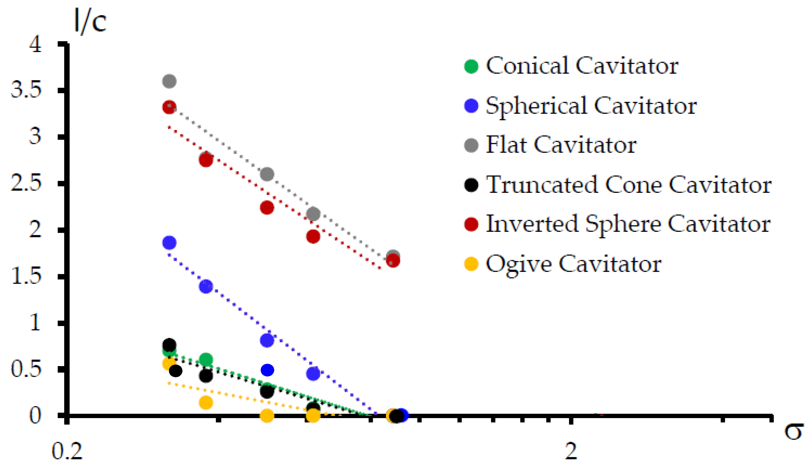
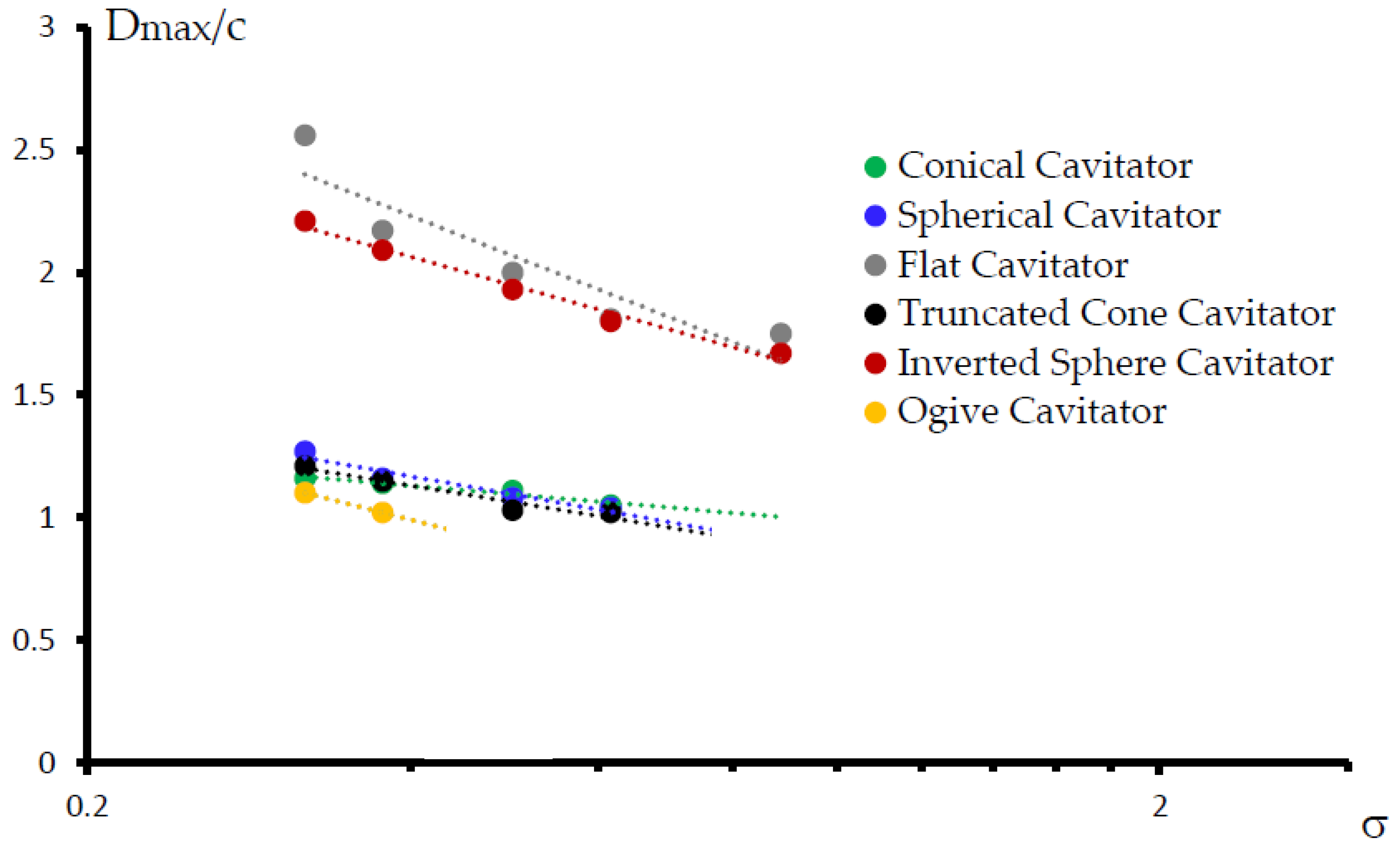
4.2. The Bubble Dimentions

The bubble dimensions (length and diameter) were measured for the different cavitators at a range of motion speeds, and the results are presented in Table 1 and Table 2, respectively. The measurement uncertainty is about ±0.5 mm.
Based on the experiments, a relation between the supercavitation bubble dimensions and the cavitation number of the flow has been deduced for all six cavitators (Figure 6 and Figure 7), according to Equation (2), which is valid in the range where bubble exists:
l / c = A σ n
where l is the bubble length, c is the diameter of the body, A , n are constants depending on the flow conditions, bubble position and form, and σ is the cavitation number of the flow, calculated according to Equation (3):
σ = P a P v 1 2 ρ U 2
where P a is the atmospheric pressure, P v is the vapor pressure of the water, ρ is the water density, U the water flow velocity relative to the body (motion speed of the underwater body). One can see from Table 1 and Table 2 and from Figure 6 and Figure 7 that the highest cavitation number (corresponding to the lowest relative flow velocity) for the onset of a natural cavitation bubble under these test conditions has been between about 1 for the cavitators with the largest influence (flat and inverted sphere cavitators) and 0.5 (for the ogive cavitator), corresponding to a relative flow speed of approximately 14 to 20 m/s, respectively.
All curves demonstrated the same general trend (which presents the value of the power n in Equation (2)) of increasing the relative length and diameter with decreasing the cavitation number (practically, when increasing the flow velocity). The two cavitators that showed the largest bubble expansion in both radial and axial dimensions were the flat cavitator and the inverted sphere cavitator. The other cavitators with decreasing bubble expansion order were as follows: the spherical cavitator (right after the first two), the conical and the truncated cone cavitators, with identical results of length in the same flow conditions; and last, the ogive, with the smallest bubble length. For the first two cavitators, the values of n were between 1.5 to 1.6; afterwards, the spherical cavitator had a 1.8 value of n; next, the values of n dropped under 1 to ~0.7 for the conical and truncated cone cavitators; and lastly, the ogive cavitator’s value was approximately n = 0.4. An interesting outcome regarding the resulting slopes is that the slopes of the curves describing the bubble length of the flat, inverted sphere and spherical cavitators were almost identical but larger than the curve slopes of the other cavitators that were also identical. Regarding the radial expansion, we can see that, according to our test data, the common relation shown in Equation (2) can present the behavior of the curves of the diameter versus the cavitation number as well, with different constants but a similar difference between the six cavitators: the flat and the inverted sphere cavitator showed the largest radial expansion, then those of the conical, truncated cone, and spherical cavitators, which were practically identical in magnitude, presenting very similar slopes as well. Last was the ogive cavitator, which was found to cause the smallest expansion, though its curve showed a similar slope to the five other cavitators.

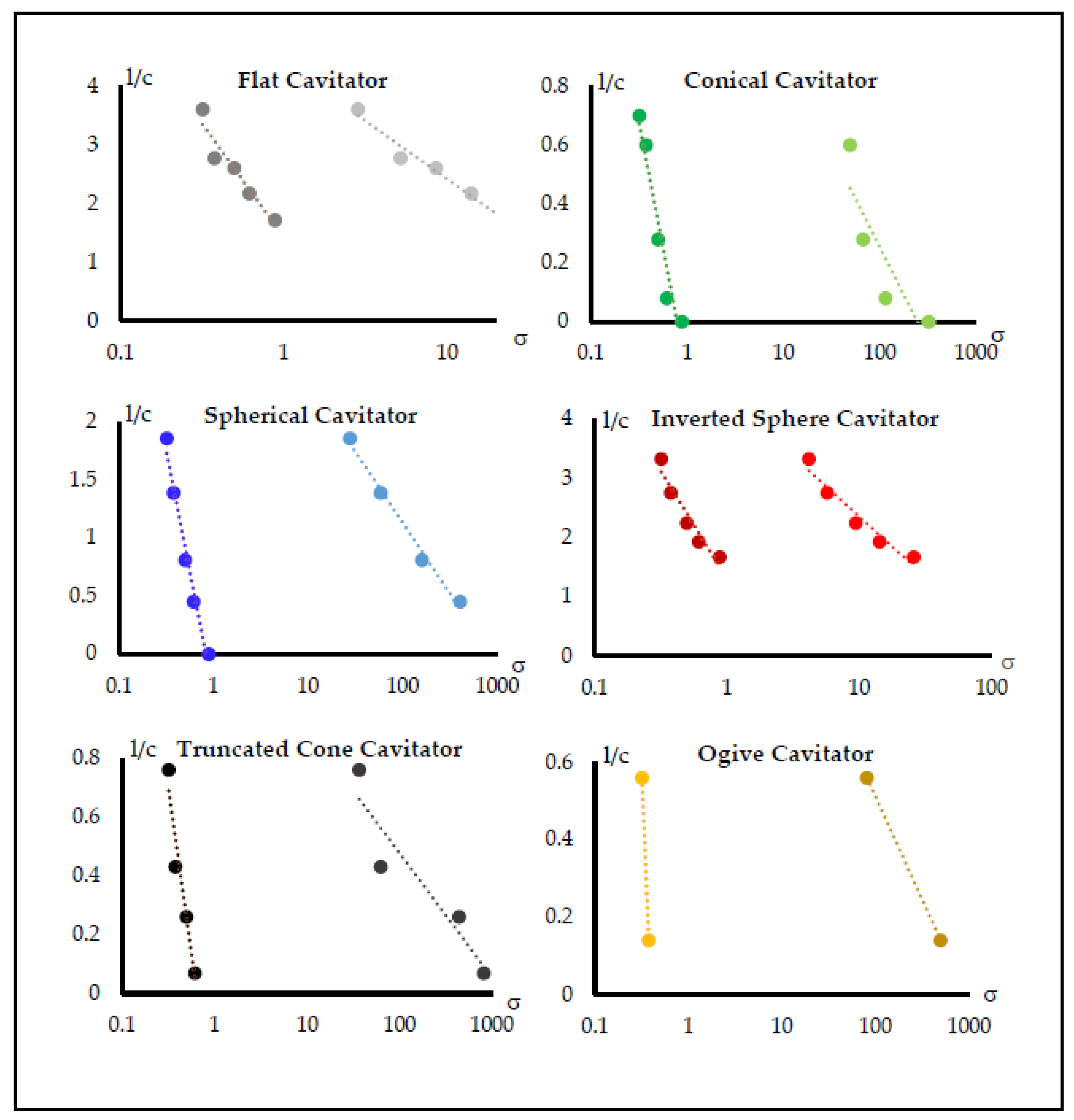
4.3. The Pressure Difference and the Cavitation Number

In order to evaluate the pressure difference created in the supercavitational flow, a control volume analysis was performed (Figure 8). The pressure difference is coupled to the cavitation creation and also leads to the cavitation bubble expansion. To calculate the pressure at a cross-section i (where the diameter of the bubble is maximal) with relation to the conditions at the cross-section t (where the front edge of the cavitator is placed), we assumed a one-dimensional flow with negligible viscosity effects. The control volume was chosen to be close to the boundaries of the system (the pool floor in the bottom and the free surface at the top), having an overall diameter of Dcv = h = 49 cm. From the conservation of mass, one can find the relation between the velocities at i and t cross-sections:
u i = u t A t A i
where u i and A i are the flow velocity and cross-section i, respectively ( u t , A t are the corresponding values at the cross-section t). The cross-section is calculated as an annular surface with diameter h minus the cavitator diameter at cross-section t and minus the bubble maximal diameter at cross-section i. Using the Bernoulli equation on a flow streamline between the initial cross-section t and a cross-section i and substituting Equation (4), we derive the pressure difference between section i and section t:
Δ P = P i P t = 1 2 ρ u t 2 ( 1 ( A t A i ) 2 ) ρ g h
where P i , P t are the pressures in section i and t, correspondingly, g is the gravitational acceleration, ρ is the density of the water, and h is the height difference. As the height contribution is three orders of magnitude smaller than the dynamic pressure, ρ g h / 1 2 ρ u 2 O ( 10 3 ) , this term in Equation (5) can be neglected.
Figure 9 shows the pressure difference established during the supercavitation bubble creation for the six cavitators. The largest pressure difference is predicted for the flat cavitator, then for the inverted sphere cavitator, and lastly for the other four. For all six cavitators, the pressure difference versus the velocity shows quadratic behavior as predicted by Equation (5). The pressure difference and the increase in flow velocity are both coupled to the expansion and growth of the cavitation bubble.
In a duct (bounded) flow, Arad Ludar and Gany [20] revealed that the cavitation bubble shape was dictated by the duct geometry, practically keeping a constant cross-section for the water flow between the supercavitation bubble boundary and the duct walls. In that case, bodies of the same diameter but of different cavitator (nose) shapes exhibited the same supercavitation bubble shape, though at different flow velocities. Contrarily, in a free-surface situation, this behavior no longer holds. The cavitator role in determining the supercavitation bubble development and dimensions (expanding and extending) was found to be fundamental and crucial.
Examining the bubble length development along the body with all six cavitators, a major difference in the curve magnitudes and slopes appears when defining the cavitation number for a different pressure difference characterizing the system. Calculation of the cavitation number as suggested in Equation (3) shows different results than calculation using the pressure difference from Equation (5) (see Figure 10). To learn about the bubble shape evaluation, the way of calculating the cavitation number describing the flow conditions should be chosen properly. The issue has not been treated in the past. The way of calculating the cavitation number is usually chosen according to the trivial factors describing the flow or based on the obvious characteristics as summarized by Franc and Mitchel [19]. The change in calculating the cavitation number not only changes the observation of the bubble development tendency with the flow conditions but may also change the conclusion from the comparison between the cavitators. The insights about the cavitator role in the supercavitation development are affected by the cavitation number calculation. The purpose of bringing up this issue and demonstrating it in Figure 9 is to make one aware of the way the cavitation number was defined when comparing results from different studies.

5. Conclusions

In the case of a duct (bounded) flow, the wall has a significant influence on the flow regime and on the development of a supercavitation bubble on a body within the flow. Contrarily, in a free-surface flow, the cavitator geometry is the most significant factor in determining the supercavitational flow, the onset of cavitation, as well as the bubble development and dimensions. Testing six different cavitators at the same flow conditions and examining the bubble development for each of those cavitators, one observes that a supercavitation bubble is created at the lowest flow velocity by a cavitator generating the largest disturbance in the flow (the flat cavitator), implying a more rapid change in the flow regime. The bubble created at the highest flow velocity occurred for the cavitator causing the least and more moderate disturbance in the flow; this was the ogive cavitator. In all cases, supercavitation relative bubble length and diameter were found to increase with decreasing the cavitation number (actually, increasing the flow velocity). Although certain cavitators affected the development of the bubble with the cavitator number in a similar manner, the bubble dimensions (both diameter and length) were different for the different cavitators. One significant conclusion is about the influence of the cavitation number calculation in examining the supercavitational flow. While examining the bubble length development along the body with all six cavitators, one can observe a substantial difference in magnitude and slope of the curves for different ways of defining the cavitation number, in particular the characteristic pressure difference chosen for the calculation. Hence, one should carefully examine the cavitation number calculation when comparing data from different investigations to avoid erroneous conclusions and misleading interpretations.

Author Contributions

This is academic research. It was conducted in full collaboration and involvement of both authors, as is commonly undertaken by a PhD student (L.A.L.) and thesis advisor (A.G.), with regard to conceptualization, evaluation, and presentation of the results. All authors have read and agreed to the published version of the manuscript.

Funding

This research received no external funding.

Institutional Review Board Statement

Not applicable.

Informed Consent Statement

Not applicable.

Data Availability Statement

Not applicable.

Conflicts of Interest

The authors declare no conflict of interest.

References

  1. Logvinovich, G.V.; Serebryakov, V.V. On methods of calculating a shape of slender axisymmetric cavities. Hydromechanics 1975, 32, 47–54. [Google Scholar]
  2. Serebryakov, V.V. Asymptotic solutions of axisymmetric problems of the cavitational flow under slender body approximation. In Hydrodynamics of High Speeds; Chuvashian State University: Cheboksary, Russia, 1990; pp. 99–111. [Google Scholar]
  3. Serebryakov, V.V. The models of the supercavitation prediction for high-speed motion in water. In Proceedings of International Scientific School; HSH-2002: Chebocsary, Russia, 2002. [Google Scholar]
  4. Semenenko, V.N. Artificial Supercavitation. Physics and Calculation. In Proceedings of the RTO Lecture Series 005 on Supercavitating Flows, Brussels, Belgium, 12–16 February 2001. [Google Scholar]
  5. Savchenko, Y. Supercavitation-Problems and Perspectives. Available online: http://resolver.caltech.edu/cav2001:Lecture.003.2001 (accessed on 1 August 2022).
  6. Wu, T.Y.T.; Whitney, A.K.; Brennen, C. Cavity-flow wall effects and correction rules. J. Fluid Mech. 1971, 49, 223–256. [Google Scholar] [CrossRef]
  7. Ahn, B.K.; Lee, T.K.; Kim, H.T.; Lee, C.S. Experimental investigation of supercavitating flows. Int. J. Nav. Archit. Ocean. Eng. 2012, 4, 123–131. [Google Scholar] [CrossRef]
  8. Ahn, B.K.; Jeong, S.W.; Kim, J.H.; Shao, S.; Hong, J.; Arndt, R.E. An experimental investigation of artificial supercavitation generated by air injection behind disk-shaped cavitators. Int. J. Nav. Archit. Ocean Eng. 2017, 9, 227–237. [Google Scholar] [CrossRef]
  9. Fridman, G.M.; Achkinadze, A.S. Review of Theoretical Approaches to Nonlinear Supercavitating Flows; Saint Petersburg State Marine Technical University, Ship Theory Department: Saint Petersburg, Russia, 2001. [Google Scholar]
  10. Kirschner, I.I.; Chamberlin, R.; Arzoumanian, S.A. Simple approach to estimating three-dimensional supercavitating flow fields. In Proceedings of the 7th International Symposium on Cavitation CAV2009, Ann Arbor, MI, USA, 16–20 August 2009. [Google Scholar]
  11. Kwack, Y.K.; Ko, S.H. Numerical analysis for supercavitating flows around axisymmetric cavitators. Int. J. Nav. Archit. Ocean Eng. 2013, 5, 325–332. [Google Scholar] [CrossRef]
  12. Brennen, C. A numerical solution of axisymmetric cavity flows. J. Fluid Mech. 1969, 37, 671–688. [Google Scholar] [CrossRef]
  13. Kinnas, S.A. The prediction of unsteady sheet cavitation. In Proceedings of the 3rd International Symposium on Cavitation, Grenoble, France, 7–10 April 1998. [Google Scholar]
  14. Scardovelli, R.; Zaleski, S. Direct numerical simulation of free-surface and interfacial flow. Annu. Rev. Fluid Mech. 1999, 31, 567–603. [Google Scholar] [CrossRef]
  15. Vasin, A.D. The Principle of Independence of the Cavity Sections Expansion (Logvinovich’s Principle) as the Basis for Investigation on Cavitation Flows; Central Aerodynamics Institute (TSAGI): Moscow, Russia, 2001. [Google Scholar]
  16. Shi, H.H.; Wen, J.S.; Zhu, B.B.; Chen, B. Numerical simulation of the effect of different object nose shapes on hydrodynamic process in water entry. In Proceedings of the 10th International Symposium on Cavitation, CAV2018, Baltimore, MD, USA, 14–16 May 2018. [Google Scholar]
  17. Logvinovich, G.V. Hydrodynamics of Flows with Free Boundaries; Published by the National Aeronautics and Space Administration and the National Science Foundation: Washington, DC, USA, 1973. [Google Scholar]
  18. Ahn, B.K.; Jeong, S.W.; Park, S.T. An experimental investigation of artificial supercavitation with variation of the body shape. In Proceedings of the 10th International Symposium on Cavitation CAV2018, Baltimore, MD, USA, 19 October 2016. [Google Scholar]
  19. Franc, J.P.; Michel, J.M. Fundamentals of Cavitation; Kluwer Academic Publishers: Dordrecht, The Netherlands, 2004. [Google Scholar]
  20. Arad Ludar, L.; Gany, A. Experimental study of supercavitation bubble development over bodies in a duct flow. J. Mar. Sci. Eng. 2020, 8, 28. [Google Scholar] [CrossRef]
  21. Gevari, M.T.; Ghorbani, M.; Svagan, A.J.; Grishenkov, D.; Kosar, A. Energy harvesting with micro scale hydrodynamic cavitation-thermoelectric generation coupling. AIP Adv. 2019, 9, 105012. [Google Scholar] [CrossRef] [Green Version]
Figure 1. A scheme of the physical problem.
Jmse 10 01244 g001
Figure 2. The experimental system.
Jmse 10 01244 g002
Figure 3. The examined supercavitation bodies.
Jmse 10 01244 g003
Figure 4. Bubble development for flat, conical, and spherical cavitators at different cruise speeds.
Jmse 10 01244 g004
Figure 5. Bubble development for inverted sphere, ogive, and truncated cone cavitators at different cruise speeds.
Jmse 10 01244 g005
Figure 6. The bubble length (in multiplies of body diameter) vs. the cavitation number for the six cavitators.
Jmse 10 01244 g006
Figure 7. The bubble maximal diameter (in multiplies of body diameter) vs. the cavitation number for the six cavitators.
Jmse 10 01244 g007
Figure 8. Control volume for evaluation of the pressure difference.
Jmse 10 01244 g008
Figure 9. The pressure difference in the flow for the different cavitators.
Jmse 10 01244 g009
Figure 10. The bubble length (in terms of body diameter) for the six cavitators vs. the cavitation number calculated in two ways, using Equation (3) in dark colors on the left and Equation (5) in light colors on the right.
Jmse 10 01244 g010
Table 1. The measured bubble length (in multiplies of body diameter) for different cavitators and motion speeds (the sign (-) indicates no bubble existence).
15 m/s18 m/s20 m/s23 m/s25 m/s
Conical Cavitator-0.080.280.60.7
Spherical Cavitator-0.450.811.391.86
Flat Cavitator1.712.172.62.773.6
Truncated Cone Cavitator-0.070.260.430.76
Inverted Sphere Cavitator1.671.932.242.753.32
Ogive Cavitator---0.140.56
Table 2. The bubble maximal diameter (in multiplies of body diameter) for different cavitators and motion speeds (the sign (-) indicates no bubble existence).
15 m/s18 m/s20 m/s23 m/s25 m/s
Conical Cavitator-1.051.111.141.16
Spherical Cavitator-1.041.081.161.27
Flat Cavitator1.751.8122.172.56
Truncated Cone Cavitator-1.021.031.151.21
Inverted Sphere Cavitator1.671.81.932.092.21
Ogive Cavitator---1.021.1
Publisher’s Note: MDPI stays neutral with regard to jurisdictional claims in published maps and institutional affiliations.

