Review

An Extensive Review of Liquid Hydrogen in Transportation with Focus on the Maritime Sector

by
Federico Ustolin
1,*,
Alessandro Campari
1 and
Rodolfo Taccani
2
1
Department of Mechanical and Industrial Engineering, Norwegian University of Science and Technology NTNU, 7034 Trondheim, Norway
2
Department of Engineering and Architecture, University of Trieste, 34127 Trieste, Italy
*
Author to whom correspondence should be addressed.
J. Mar. Sci. Eng. 2022, 10(9), 1222; https://doi.org/10.3390/jmse10091222
Submission received: 14 July 2022 / Revised: 18 August 2022 / Accepted: 24 August 2022 / Published: 1 September 2022
(This article belongs to the Special Issue Advanced Research in Innovative Ship Energy Systems)

Abstract

:
The European Green Deal aims to transform the EU into a modern, resource-efficient, and competitive economy. The REPowerEU plan launched in May 2022 as part of the Green Deal reveals the willingness of several countries to become energy independent and tackle the climate crisis. Therefore, the decarbonization of different sectors such as maritime shipping is crucial and may be achieved through sustainable energy. Hydrogen is potentially clean and renewable and might be chosen as fuel to power ships and boats. Hydrogen technologies (e.g., fuel cells for propulsion) have already been implemented on board ships in the last 20 years, mainly during demonstration projects. Pressurized tanks filled with gaseous hydrogen were installed on most of these vessels. However, this type of storage would require enormous volumes for large long-range ships with high energy demands. One of the best options is to store this fuel in the cryogenic liquid phase. This paper initially introduces the hydrogen color codes and the carbon footprints of the different production techniques to effectively estimate the environmental impact when employing hydrogen technologies in any application. Afterward, a review of the implementation of liquid hydrogen (LH2) in the transportation sector including aerospace and aviation industries, automotive, and railways is provided. Then, the focus is placed on the maritime sector. The aim is to highlight the challenges for the adoption of LH2 technologies on board ships. Different aspects were investigated in this study, from LH2 bunkering, onboard utilization, regulations, codes and standards, and safety. Finally, this study offers a broad overview of the bottlenecks that might hamper the adoption of LH2 technologies in the maritime sector and discusses potential solutions.

1. Introduction

In December 2019, the European Green Deal was presented [1]. The Green Deal aims to overcome different challenges such as climate change and environmental degradation. In 2022, the REPowerEU plan to rapidly reduce dependence on Russian fossil fuels and fast forward the green transition was introduced as part of the Green Deal [2]. Hydrogen will play a central role in the energy transition phase since it can be coupled with renewable energies and aid the achievement of Green Deal goals. For instance, a target of 10 million tons of domestic renewable hydrogen production and 10 million tons of imports by 2030 has been set as one of the REPowerEU plan initiatives [2]. Clean hydrogen produced by renewable energies (e.g., solar or wind) must be used to tackle global warming. However, other types of hydrogen production, such as blue hydrogen generated from natural gas in combination with a carbon capture and storage (CCS) technique to avoid the release of CO2 into the atmosphere, might be used in the energy transition phase.
One of the main issues when using hydrogen on a large scale is its very low density (0.0883 kg/m3 at atmospheric temperature and pressure [3]) which requires enormous volumes to store it. For this reason, hydrogen is either compressed or liquefied after its production. Liquid hydrogen (LH2) has a density three orders of magnitude higher (70.9 kg/m3 [3]) compared to atmospheric conditions. One of the main challenges in storing and handling LH2 is its ultra-low temperature (−253 °C at atmospheric pressure [3]) which makes it one of the coldest cryogenic fluids. In the past few decades, LH2 has been used mainly in the aerospace industry where large amounts of high energy content fuels are required to power rockets and spaceship engines. As a consequence, LH2 and its specific storage equipment still have high costs and low availability. However, LH2 seems to be one of the few solutions to transport large amounts of hydrogen over a long distance and power long-range large vehicles such as ships and airplanes. This is confirmed, for example, by the willingness of Airbus, the largest aeronautics and space company in Europe, to develop and build a zero-emission fleet composed of hydrogen-powered airplanes by 2035 [4].
Decarbonization must be attained in the transport sector which accounts for approximately one-quarter of global CO2 emissions according to the International Council on Clean Transportation (ICCT) [5]. The ICCT estimated that in the period 2019–2022, CO2 equivalent emissions from transportation will rise globally up to 11.9 Gt [5]. The marine sector is responsible for 11% of these global transportation emissions that must be drastically reduced to stop climate change-related issues. Different challenges must be faced when implementing a new fuel such as hydrogen in the maritime sector since infrastructures to store and distribute hydrogen are missing and a retrofitting of ships with hydrogen tanks, fuel cells, electric motors, or hydrogen-powered internal combustion engines is required [6]. Therefore, this transition will occur gradually and need an optimized plan in order to not waste precious investments and resources. This paper aims to highlight these challenges by providing an extensive overview of the utilization of LH2 in the transportation sector, specifically in the maritime field. The steps required for the effective deployment of hydrogen technologies will be described. Hence, the hydrogen colors and its carbon footprint are discussed at the beginning of the paper to clarify why only a few types of hydrogen production can satisfy the requirements to decarbonize the transport sector. Then, an overview of LH2 utilization in the aerospace, aviation, road, and railway sectors is given, with a focus on studies, past research projects, and future investments involving LH2 ships. Different critical aspects such as the lack of infrastructures, and technological and regulatory barriers are discussed at the end of the paper. To facilitate the reading of the article, a list of all the abbreviations used in the paper is presented in Table 1.

2. Hydrogen Production and Environmental Impact

Hydrogen as the most abundant substance in the universe can be found in nature bonded to numerous substances. For this reason, several hydrogen sources exist, such as water, hydrocarbons, and waste. Currently, the two most common hydrogen production methods are steam reforming, in which heat and water vapor are used to separate methane molecules into hydrogen and carbon, and electrolysis, where electricity is used to split water molecules into hydrogen and oxygen [7]. The description of additional hydrogen production techniques can be found in [8]. Nowadays, fossil fuels are mainly employed to produce hydrogen with consequent emissions of 900 Mt of CO2 annually [9].
Recently, many hydrogen color codes have been created to distinguish the different primary energy sources used to produce hydrogen [10]. In the literature, in some cases it is still unclear how these colors are defined, and this paper aims to serve as a reference point for this definition. The idea is to discuss the carbon footprint of the hydrogen color codes and their renewability to explore solutions to tackle greenhouse gas (GHG) emissions and consequent global warming. Life cycle analyses are required to provide the global warming potential (GWP) often measured in kg of CO2 equivalent. In addition, it must be kept in mind that hydrogen is an indirect greenhouse gas and the impact of its release into the atmosphere must be considered and assessed. Therefore, Section 2.1 introduces the hydrogen colors and their carbon footprints while the indirect GHG effect of hydrogen on the environment is discussed in Section 2.2.

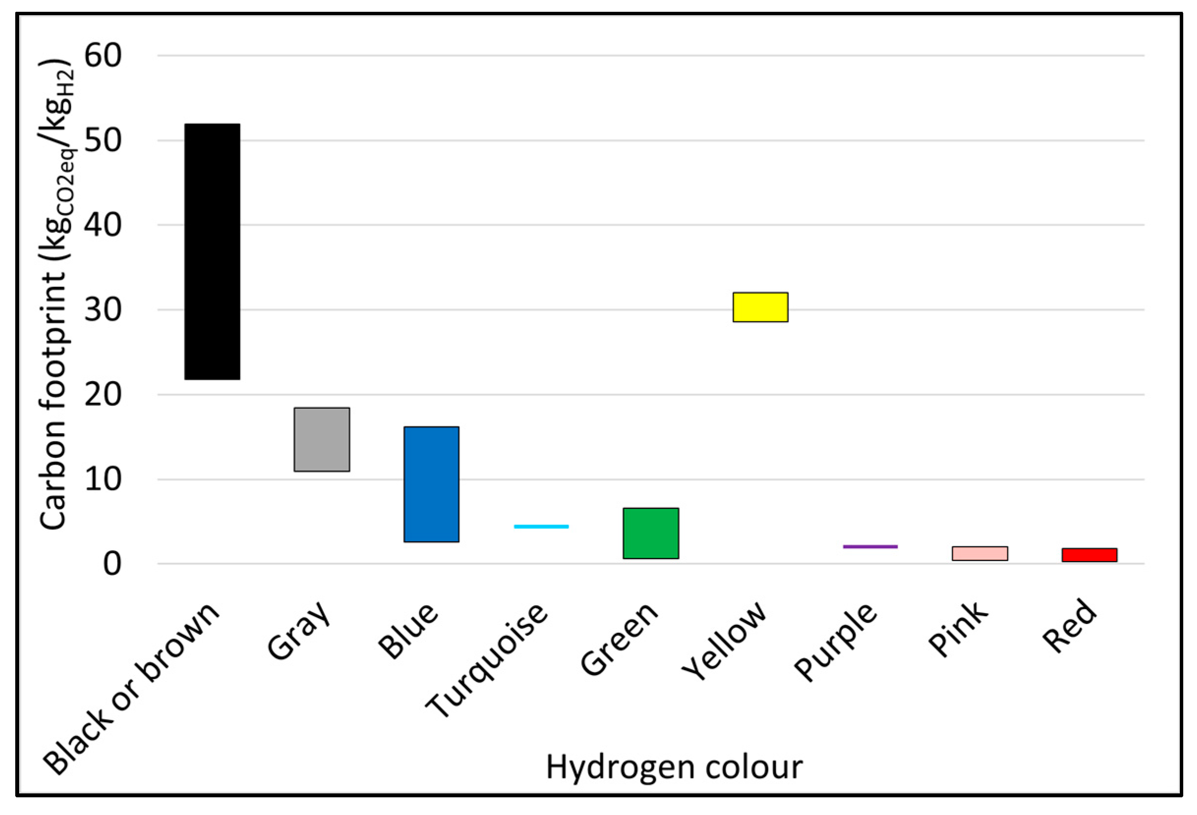
2.1. Hydrogen Colors and Carbon Footprint

The description of color codes together with their GWP estimated by different authors are reported in the following. Only the hydrogen production processes were investigated, thus the focus is not placed on the environmental impact of hydrogen storage methods. Moreover, the production costs analysis was neglected since it would not be a fair comparison for emerging techniques and it could even be difficult for well-established production methods affected by political decisions and financial markets [11].
Black and brown
When hydrogen is produced from black (bituminous) or brown coal (lignite) via gasification, it is called black or brown hydrogen. Although these color codes can be found on different websites [12,13,14] and reports [15], they are not widely used in scientific literature. Ajanovic et al. [10] propose to indicate hydrogen produced from fossil fuels without carbon capture utilization and storage (CCUS) as gray hydrogen. On the other hand, hydrogen emissions and costs largely vary depending upon the primary energy source and production technique, and the purpose of the color codes is to identify these characteristics. For this reason, brown/black and gray hydrogen are treated separately in this study. The process to produce black or brown hydrogen is coal gasification. Different types of coal gasification exist and these all operate at a temperature higher than 900 °C [16]. In general, air and steam are used at high temperatures during gasification, and CO2 and hydrogen are the main products of this process. Different carbon emission values in the range 21.8–51.9 kgCO2eq/kgH2 were estimated in [17,18]. Even though different modifications of the current gasification process have been proposed to reduce its emissions [17,18], the carbon footprint of this production technique remains one of the highest compared with other methods.
Gray
As anticipated, hydrogen is called gray when generated from methane (natural gas) through the steam reforming method where water and heat are used and the CCUS technique is not employed. Currently, most of the hydrogen produced worldwide is gray. The main products of this reaction are hydrogen and CO2. Again, the range of GHG emission values provided in the literature is broad, between 10.9–18.4 kgCO2eq/kgH2 [19,20]. The highest value might seem quite conservative since the second highest value is 13.8 kgCO2eq/kgH2 [21]. A reason for this could be that Howarth and Jacobson [20], who estimated a carbon footprint of 18.4 kgCO2eq/kgH2, considered also the emission of fugitive methane (unintentional release) from the hydrogen production plant.
Blue
Gray hydrogen becomes blue when CCS is adopted. The emissions can be drastically reduced. However, various production techniques can be employed to generate blue hydrogen; thus, the CCS efficiency and the fugitive methane amount can vary. For instance, Oni et al. [22] estimated the carbon footprints of autothermal reforming and natural gas decomposition (3.91 and 4.54 kgCO2eq/kgH2, respectively). Furthermore, the authors assumed 85% and 52% carbon capture for steam reforming, obtaining GHG emissions equal to 6.66 and 8.20 kgCO2eq/kgH2, respectively [22]. Even lower values were estimated by Antonini et al. [23] (2.6 kgCO2eq/kgH2). Moreover, these authors claimed that even negative GHG emissions could be reached by using biomethane for hydrogen production and the biogas digestate as fertilizer. On the other hand, other authors concluded that the blue hydrogen carbon footprint can be much higher (16.7 kgCO2eq/kgH2 [20]) if a methane leakage rate of 3.5% is considered. According to the International Energy Agency (IEA) [9], methane emissions can have an impact of 5.2 kgCO2eq/kgH2 in addition to the CO2 emissions. Recently, a paper written by Romano et al. [24] commenting on the work of Howarth and Jacobson was published. Romano et al. argued on different conservative assumptions made in the paper and demonstrated how the carbon footprint may be reduced drastically. This is an example to explain how arduous the determination of the blue hydrogen carbon footprint is and that it strongly depends on the initial assumptions, making it quite complex to attain a precise value or at least a narrower range. Nevertheless, leakages must be avoided to reduce the environmental impact of hydrogen production.
Turquoise
This color is similar to the previous ones in the sense that methane and a thermal energy source are used to produce hydrogen. The main difference is that methane pyrolysis is used instead of steam reforming. Specifically, three processes are considered for pyrolysis: thermal, plasma (Kvaerner process), and catalytic decompositions [10,25,26]. The by-products of this process are hydrogen and solid carbon, thus theoretically it does not emit any CO2. Another advantage is that carbon can be sold as a co-product as well [27]. On the other hand, the method can still be subject to fugitive methane. Interestingly, a net negative carbon footprint might be achieved by thermal decomposition if large amounts of power from the process are produced [27]. Despite this technique having been known for decades, it has not been applied to hydrogen production on a large scale yet.
Green
Green hydrogen is one of the most suitable production solutions to tackle the GHG emission issue. Hydrogen is produced from water via electrolysis, hence oxygen is also a by-product. In this study, hydrogen can be considered green only if the electricity generated from renewable sources is used to feed the electrolyzers. Hydrogen generated from water by using electricity from the grid is indicated with the yellow color. However, it is still not clear if this is always the case [10]. Despite the fact that the electrolysis process does not release any carbon, the green hydrogen lifecycle analysis carried out by Dufour et al. [28] revealed GHG emissions equal to 6.6 kgCO2eq/kgH2 assuming that the electricity is generated using photovoltaic solar panels. For the same primary energy source, Cetinkaya et al. [29] estimated a lower value of 2.4 kgCO2eq/kgH2. One of the most crucial parameters of solar panels’ life cycle that increases GHG emissions is their durability [28]. Instead, Ghandehariun and Kumar [30] estimated a GWP as low as 0.68 kgCO2eq/kgH2 for a wind-based hydrogen production plant. Similar values were obtained by Valente et al. [31] for wind power (0.63 kgCO2eq/kgH2) and hydropower systems (0.77 kgCO2eq/kgH2). Finally, Dincer [32] and Noussan et al. [33] proposed to characterize the hydrogen production from biomass through different processes as green hydrogen.
Yellow
The main difference between green and yellow hydrogen is that the latter is produced by using electricity supplied from the grid. This means that the total GHG emissions of yellow hydrogen mainly depend on how the electricity has been generated, and on the energy mix. For instance, the IEA [34] provided an example of hydrogen produced from water via electrolysis using the French electricity grid with an intensity of 50–70 gCO2/kWh, estimating a GHG emission of 2.6–3.6 kgCO2eq/kgH2. If the same production method is adopted in a country where the electricity has the global average carbon intensity (475 gCO2/kWh [34]), the GHG emissions when producing hydrogen would be three times higher. Assuming that the electricity is generated using coal-fired power plants, yellow hydrogen could have a higher environmental impact than brown and black hydrogen, as has been demonstrated by different studies [17,21], with a carbon footprint up to 32.0 kgCO2eq/kgH2 estimated in [35]. Some confusion exists for this color code as well, since on a few web pages [12,14,36] it is defined as hydrogen produced through electrolysis but using solar power. The authors of this paper encourage scientists and stakeholders to follow the indications provided in this study because solar power is already included in the green hydrogen code. In a scenario where yellow hydrogen is generated via solar power, green hydrogen would include both renewable and non-renewable energy sources leaving broad uncertainties about its carbon footprint.
Purple, pink, and red
Purple, pink, and red color codes have in common the use of nuclear energy to produce hydrogen. Heat, electricity, or both can be exploited to produce hydrogen from water through electrolysis, a thermochemical cycle [31], or a hybrid cycle. Ajanovic et al. [10] defined purple hydrogen as that produced from nuclear electricity through electrolysis. Although online this type of hydrogen is also called pink or red [12,14,36], the definition provided by Ajanovic et al. [10] is kept in this work to avoid adding confusion to the color codes. The authors of this paper suggest using the color red to indicate hydrogen generation through thermochemical cycles, while using pink (a color between red and purple) for hybrid cycles such as high-temperature electrolysis or hybrid thermochemical cycle. Valente et al. [31] conducted a life cycle analysis on different case studies by estimating carbon and acidification footprints of hydrogen production through nuclear power. In particular, the GHG emissions of purple (alkaline electrolysis), pink, and red were 2.0, 0.4–2.0, and 0.3–1.8 kgCO2eq/kgH2. On the other hand, the life cycle analysis on nuclear-based hydrogen production carried out by Valente et al. [31] performed badly in terms of the non-renewable energy footprint compared to steam methane reforming. Finally, nuclear power might be a good option to generate hydrogen and reduce GHG emissions during the energy transition phase, but all the drawbacks posed by this technology (viz. nuclear waste, safety) must be considered.
Aqua and white
Yu et al. [37] proposed a new method to produce hydrogen from oil sands (natural bitumen) and fields without emitting any CO2. The production process involves the utilization of electricity to supply air separation units, with the consequent injection of oxygen into the oil reservoir where a water-gas shift reaction takes place at 350 °C [37]. Therefore, synthesis gas and CO2 are generated but left underground, while hydrogen is extracted using palladium alloy membranes. The authors suggested calling it “aqua” hydrogen since it still exploits fossil fuel energy (blue) but does not emit CO2 (green). Beyond the avoidance of emissions and the exploitation of exhausted oil reserves, the hydrogen production cost is very promising (0.23 US$/kgH2). On the other hand, hydrogen extraction from fossil fuels is not a renewable method; thus, it can be advantageous during the energy transition phase but not in the long term. Furthermore, the carbon footprint of aqua hydrogen has not been determined yet. According to the previous observations, the GHG emissions would depend on the type of electricity (renewable or not) used in the air separation unit. Instead, Boretti [38] adopted the color aquamarine for hydrogen generated by thermochemical methane pyrolysis with a carbon catalyst through solar power. Methane pyrolysis recalls turquoise hydrogen, but in this case the heat is generated by a renewable source. Again, this is not a renewable method since it requires methane gas. Finally, white hydrogen has been defined differently, creating more confusion in the color codes. Boretti [39] assigned the white color to hydrogen produced by solar thermochemical water splitting. Therefore, this technology exploits thermal solar power and water, which are both renewable. However, online sources [12,14,36,40] describe differently white hydrogen as that which is geologically naturally occurring underground when generated by fracking. No scientific sources were found for this latter definition, hence the white color code proposed by Boretti [39] is kept in this paper.
In Table 2, all the hydrogen color codes previously described are presented by specifying their hydrogen and energy sources, as well as the techniques required to produce the hydrogen and their carbon footprints. In Figure 1, the carbon footprint estimated for each hydrogen color is depicted to graphically compare their environmental effect. It is important to notice that black (or brown) hydrogen has the highest carbon footprint, and the electrolysis process is not always the cleanest solution. For instance, yellow hydrogen uses electricity from the grid to feed the electrolysers, generating even higher emissions than gray hydrogen.
Potentially, it would be possible to determine the carbon footprint of the hydrogen color codes and conclude their sustainability. However, the carbon emissions estimation for some production techniques such as gasification and steam reforming can be arduous since they depend on several parameters (e.g., fugitive methane, CCS efficiency). In fact, very large GWP ranges were obtained by different authors for black, brown, gray, and blue hydrogen. A few conclusions can be drawn from this analysis with the available data: (i) black, brown, and yellow hydrogen have the highest carbon footprints, (ii) blue and turquoise hydrogen have the potential to achieve negative GHG emissions, (iii) green and nuclear-based hydrogen currently have the lowest carbon footprints, but (iv) only green, white, and blue (if produced from biomethane) hydrogen can be considered renewable.

2.2. Indirect Greenhouse Gas Effects

When assessing the environmental impact of hydrogen technologies, the effect of releasing hydrogen into the atmosphere due to leakages or venting must be investigated. Despite hydrogen being non-toxic and not corrosive, it is a short-lived indirect greenhouse gas (GHG) [41,42,43]. This means that hydrogen has an atmospheric lifetime of a few years before it completely oxidizes with hydroxyl radical (OH) [41,42,43]. The concentration of greenhouse gases increases in the troposphere and stratosphere due to hydrogen oxidation [42,43,44]. More precisely, this phenomenon leads to:
  • Reduction of OH in the troposphere.
  • Formation of ozone (a GHG) in the troposphere.
  • Formation of water vapor in the stratosphere.
The consequences of the abovementioned phenomena are as follows: Methane reacts with OH and decomposes in the troposphere. A reduction of OH will increase the atmospheric lifetime of methane. Always in the troposphere, a chain reaction starting from atomic hydrogen (a product of its oxidation) generates ozone, which is a GHG and facilitates the warming effect. Finally, water vapor is another product of hydrogen oxidation. If it is generated in the stratosphere, it stimulates the cooling of this latter with consequent enhancement of the warming effects. Additional details and information can be found in [41,42,43,44,45].
Recently, Ocko and Hamburg [45] modelled the consequences of hydrogen leakages in the atmosphere by considering different timescales. The authors noted that this type of analysis strongly depends on the selected timescale and the unknown leakage rate from hydrogen applications. Therefore, additional studies are needed to assess the real effect of hydrogen releases on atmosphere warming [45]. However, it can be concluded that hydrogen leakages must be avoided not only for environmental purposes but also for economic and safety aspects.

3. Liquid Hydrogen in the Transportation Sector

The liquefaction process is one of the most suitable techniques to increase hydrogen density. This is an energy-demanding process compared to hydrogen compression. The theoretical minimum energy required to liquefy hydrogen is equal to 2.3 kWh/kgLH2 if hydrogen is supplied at a pressure of 20 bar. Moreover, the catalytic conversion from normal (75% ortho-hydrogen and 5% para-hydrogen) to 100% para-hydrogen necessitates 0.65 kWh/kgLH2 [46]. Liquid hydrogen is converted to para-hydrogen in order to limit boil-off gas formation during storage [47]. In practice, up to 13.3 kWh/kgLH2 are required for the liquefaction depending upon the technique employed, the amount of hydrogen, and the efficiency of the plant [48]. This energy amount corresponds to almost 40% of the hydrogen’s lower heating value (33.3 kWh/kg [48]). On the other hand, power of approximately 3.0 kWh/h is needed to compress gaseous hydrogen up to 700 bar [49].

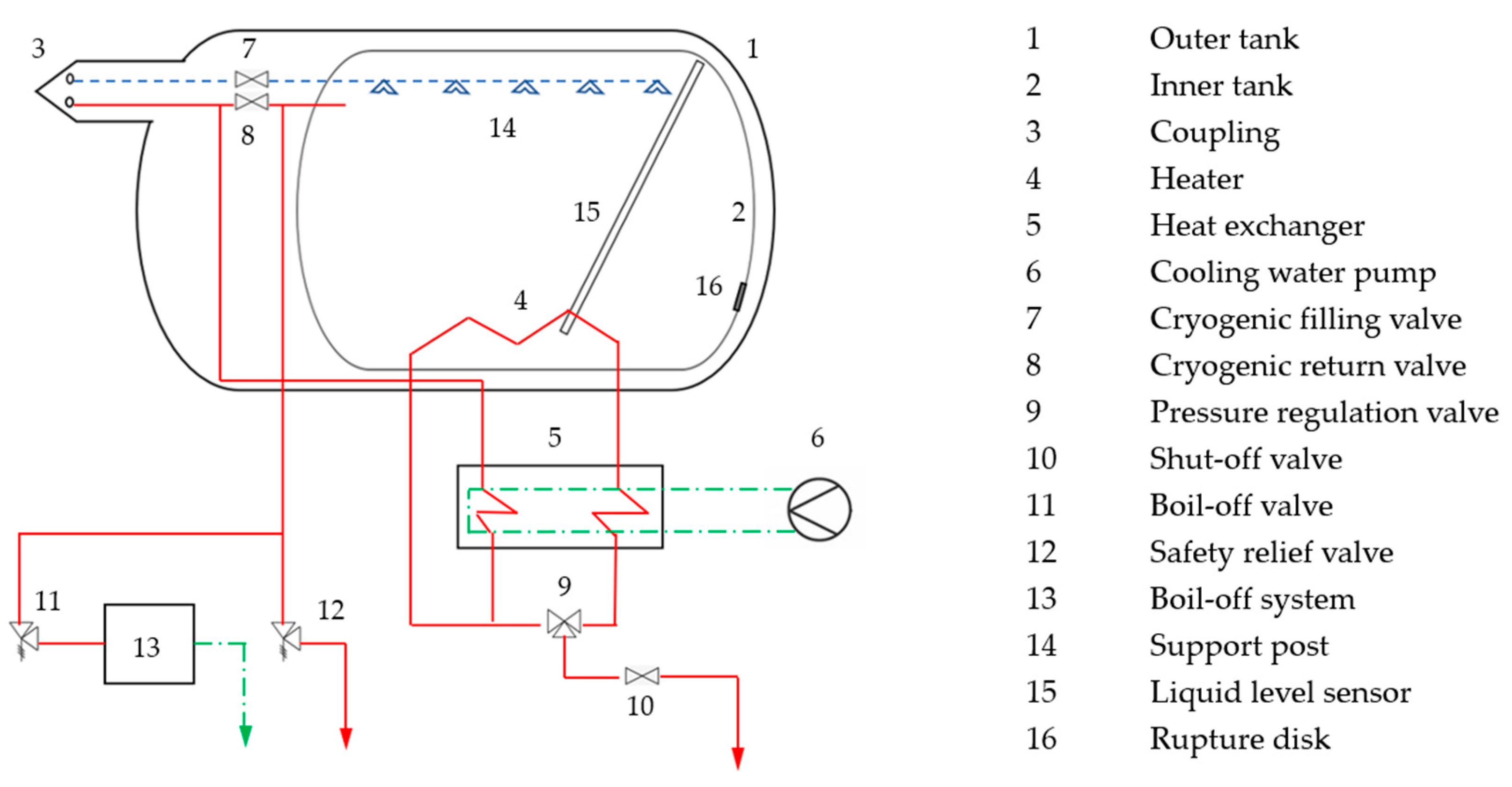
3.1. Liquid Hydrogen Storage

Cryogen storage tanks are typically cylindrical, double-walled containers with capacities of up to 10 kg of LH2 (i.e., 170 L of volume) for passenger cars [50]. The insulation system, for example, can be made of 70 layers of aluminum foils or aluminized polymers, separated by glass fibers or polymer spacers with a total thickness of approximately 30 mm [50]. It is designed to allow a boil-off loss lower than 1.5% per day [50]. The double-walled filling tube, the pressure relief valve, and the safety vent pass through the insulation system. Generally, a super-insulated tank operates at a pressure of around 4 bar, and the maximum allowable pressure before venting is 7 bar [50]. The internal pressure is controlled through an electric heating device [51,52]. Michel et al. suggested an improved pressure management system, in which part of the gas is heated and routed back inside the tank to transfer its heat to the liquid fuel depending on the pressure measured in the exit line. This solution avoids any electricity consumption and recovers part of the waste heat from the engine [53]. An example of an LH2 tank for passenger cars was fabricated in 2006 by the Austrian company Magna Steyr for the BMW Hydrogen 7. It is constituted of a double-walled steel vessel with an internal wall 2 mm thick, a 30 mm high-vacuum super-insulation system, and another 2 mm external wall. The pressure in the vacuum jacket is 0.1 bar at 20 K [54]. A normal dormancy period for these cryogenic tanks is slightly lower than 12 days. A schematic of an LH2 tank for automotive application is depicted in Figure 2.
On the other hand, large amounts of LH2 are stored in double-walled spherical tanks to maximize the volume-to-surface ratio. One example is the largest LH2 tank in the world installed at the NASA Kennedy Space Center. This tank has a volume of 3800 m3 and it has been in operation since the 1960s [46]. Instead of multi-layer insulation (MLI), the vacuum jacket is filled with perlite powder. Recently, NASA commissioned the construction of a larger stationary tank with a volume of 1.25 million gallons (approx. 5683 m3) and with insulation composed of glass bubbles which have been demonstrated to perform better than perlite, to support future missions to the Moon and Mars [55]. Moreover, an innovative heat exchanger system called integrated refrigeration and storage (IRAS) will be installed in the tank to minimize the boil-off and the scheduled releases through the pressure relief valve (PRV) [56,57].
Copious amounts of liquid hydrogen can be transferred using a cryogenic pump. This component needs to reach a pressure slightly higher than 5 bar (maximum operating pressure of the receiving tank), but the desired flow rate ranges between 300 and 1200 kg/min. An alternative method of transferring the LH2 is to use a pressure-build loop, in which a certain amount of liquid hydrogen is evaporated and then returns as gaseous hydrogen to the top of the tank, pressurizing it enough to drive the flow. This method does not require power, does not involve moving parts, but increases the pressure and heat content of the storage tank, thus increasing overall boil-off losses [58].
The refueling stations should also have a flow rate meter to keep track of fueling, pressure sensors, relief devices for safety reasons, a dispenser hose, and a connector to make the connection to the tender car. Vessels for cryogenic fuels are not designed to withstand high pressures and adding liquid to the tank would rapidly over-pressurize the remaining gas phase. Therefore, the gaseous hydrogen must be removed from the empty tank as it is filled with liquid. This can be done by simply venting the gas into the atmosphere. The total component cost for each refueling station is driven by the cost of the super-insulated LH2 tank, depending on the size of the storage system.

3.1.1. Materials for LH2 Tanks

Due to the extremely low temperature of liquid hydrogen (20 K), special materials are required for storage and transportation containers. The main requirements are the adaptability of materials in a liquid hydrogen environment, resistance to hydrogen embrittlement, mechanical properties, and thermophysical properties at cryogenic temperatures [8]. Considering the wide range of applications of LH2 technologies, the requirements for container materials are not the same for maritime, aerospace, automotive sectors, or stationary applications.
Stainless steel is the cryogenic material most widely used for liquid hydrogen vessels in applications where the weight of the containment system is not a constraining factor. Austenitic stainless steels are usually the first choice for liquid hydrogen transportation vessels due to their reliable performance at cryogenic temperatures [59]. The crystal structure of austenitic steels is face-centered cubic, thus implying a superior plastic deformation ability. With the decrease in temperature, the strength of the material tends to be improved while maintaining acceptable plasticity and impact resistance [60]. The macro properties of each grade of stainless steel are determined by the composition elements of the alloy, thus determining their suitability for different applications. In general, greater stability of the alloy at low temperatures can be obtained by adding a higher content of Ni and Cr [61].
The Cr-Ni austenitic stainless steels (300 series) are widely used for the storage of cryo-liquefied gases due to their superior overall performance. The difference in the alloy elements of stainless steel directly affects the final application of materials. For example, 316L stainless steel is suitable for the marine environment, since the greater content of Mo improves the resistance of steel to chloride ion corrosion; 321 stainless steel is used in environments where high corrosion resistance and heat resistance are required since the added Ti element improves the resistance to intergranular corrosion and the strength at elevated temperature [60]. The metallic materials suitable for cryogenic applications and hydrogen service are summarized in Table 3. The material costs have been categorized based on the market values found in [62].
The materials exposed to hydrogen manifest a detrimental effect on the tensile properties, fracture mechanical properties, and fatigue performance. This phenomenon is widely known as hydrogen embrittlement and results in material crack initiation and subsequent fracture due to the absorption and permeation of hydrogen atoms through the metal lattice [63,64,65]. For austenitic stainless steels, the elevated stability at low temperatures ensures good resistance to hydrogen embrittlement. However, this material damage is more likely to occur in metastable 304 stainless steel than in 310 and 316 thanks to their superior phase stability. The different microstructures and surface treatments have a significant influence on the material’s susceptibility to hydrogen embrittlement [66]. Fan et al. studied the effect of grain refinement on hydrogen embrittlement of 304 stainless steel, demonstrating that a smaller grain size can significantly reduce the stress concentration and the susceptibility to hydrogen embrittlement [67]. Hence, tight control of all the aspects of material forming, the maximization of the stability of the alloy, and the reduction of concentrated stresses are particularly important to increase the hydrogen embrittlement resistance of austenitic stainless steels.
Metals exposed to cryogenic temperatures generally manifest an increase in elastic modulus, tensile strength, and yield strength, along with an increase in fatigue performance and endurance limit [68]. The ductile–brittle transition characteristic of materials influences their plasticity at low temperatures [8]. Most metallic materials with body-centered cubic structures show a sharp decrease in plasticity below the ductile–brittle transition temperature; they cannot be used under cryogenic conditions since the significant decrease in the plasticity can induce brittle crack initiation and fractures [69]. On the other hand, for materials without brittle transition, the elongation tends to increase with decreasing temperature. To assess the suitability of materials to operate in a low-temperature environment, low-temperature impact toughness tests, drop weight tests, full thickness tests, and fracture mechanics tests are commonly performed. It is often necessary to carry out low-temperature impact toughness testing on the base metal, welds, and heat-affected zones (HAZs) for liquid hydrogen storage tank materials. The performance of weldments proves to be often worse than that of the base metal.
The plasticity and toughness of austenitic stainless steels do not show a significant reduction with the decrease in temperature, thanks to the face-centered cubic crystal structure.

3.2. Aerospace and Aviation Industry

In the past, LH2 has mainly been used in the aerospace industry, especially in the last 60 years due to space missions [50]. Despite LH2 utilization being proposed already in 1903 by Tsiolkovsky [70], it has only been investigated for aerospace applications since 1945 [50]. LH2 has been mostly used together with liquid oxygen (LOX) in rocket engines. Even though LH2/LOX systems have an exceptionally high specific impulse performance, their utilization was always implemented in rocket upper stages due to their low density which results in bulky tanks and additional weight and drag (aerodynamic resistance) for the rocket. Therefore, LH2/LOX propellants were used for the first time in the upper stages of the Centaur and Saturn space programs in 1958–1959. Centaur was an unmanned space missions program while Saturn was a manned moon voyage one [70]. Additional details on the development of LH2/LOX rocket engines can be found in [50]. After several technical difficulties and a few failures, the first successful launch of a NASA Atlas-Centaur rocket occurred in 1963. Between 1967 and 1972, during the Apollo moon flights, LH2/LOX engines were installed in the second and third stages of the Saturn-V rockets [50]. In parallel, the European space agency began to test LH2/LOX engines for the Ariane rocket program in 1964. The LH2/LOX Vulain-2 engine was then installed on the Ariane-V rocket. Also in Japan, LH2 has been used for rockets since 1986 [71]. LH2 and LOX were used again in the US as propellant fuels on board the space shuttle. Finally, it has been demonstrated that LH2 can be employed as a fuel for spaceplanes since it is a light fuel and its extremely low temperature can be exploited to cool the aerodynamic surface heated by air friction [50]. It must be added that NASA has employed hydrogen to power fuel cells (polymer electrolyte and alkaline types) to generate all the electricity and drinkable water on board spacecraft since 1965 [72].

Aviation Sector

Despite LH2 having been considered as airplane fuel already in 1938 by Sikorski, the first successful flight test was carried out in 1957 by a B-57 aircraft with one of the two engines powered by hydrogen stored on board in an LH2 tank with a volume of 1.7 m3 and pressurized by helium [50,70,73,74,75,76,77]. LH2 was used as a fuel to power one of the three engines of the Tu-155 aircraft developed by the Russian Tupolev company for the first time in 1988 [50,73,76]. The same year, a small four-seat Grumman-American “Cheetah” was the first and only airplane that flew solely powered by LH2 stored in a 40-gal tank (approx. 182 l) [50,76,77]. Even though the flight lasted barely 36 s at an altitude of 100 ft (30.5 m), it was recognized by the US National Aeronautic Association as a world record [77]. Other concepts of LH2 fueled airplanes were proposed as part of different projects, such as the Suntan project started in 1956 where a supersonic high-altitude reconnaissance aircraft was designed [50], or the Cryoplane project where passenger planes were being considered to be converted to LH2 propulsion [50,78]. Thorough descriptions of the abovementioned LH2 airplanes can be found in [50,70,76,77,79]. In 2012, Boeing developed and tested an LH2-powered high altitude long endurance (HALE) unmanned aerial vehicle (UAV) called Phantom Eye [80,81]. This UAV is designed to carry 450 lb (240 kg) of payload, fly at an altitude of 65,000 ft (approx. 19.8 km) at a cruise speed of 150 kt (approx. 292 m/s), with an endurance of 4 days [81,82]. The Ion Tiger is another UAV, developed by the Naval Research Laboratory (NRL), which has been the only UAV powered by LH2 [83]. More specifically, the Ion Tiger was a fixed-wing UAV with a 20.46-l LH2 tank installed on board and it established the endurance world record for small electric UAVs by continuously flying for 48 h and 1 min [84]. Recently, the study carried out jointly by the Clean Sky 2 Joint Undertaking and Fuel Cell and Hydrogen 2 Joint Undertaking [85] concluded that interest in LH2 powered airplanes has increased. Other proof of this are the three concepts for the world’s first zero-emission commercial aircraft powered by hydrogen revealed by Airbus in 2020 [4].

3.3. Road Transport

The first example of an LH2 fueled road vehicle dates back to 1971 when the Perris Smogless Association in the USA converted a Ford F250 pickup into the world’s first LH2/LOX fueled car. Two LH2 tanks (for a total capacity of 300 L) and a LOX tank were installed on the truck. The car was capable of running 160 km and 25 h [46]. Research on LH2-fueled vehicles and refueling technologies was conducted between 1979 and 1981 in cooperation between the German Aerospace Center (DLR) and the Los Alamos National Laboratories (LANL). DLR provided the onboard LH2 tank and the refueling technology. A Buick Century four-door sedan was adapted by LANL and proved its ability to run for 133 h, 3540 km, and to be refueled at least 60 times [86]. In 1967, General Motors and Opel started their research on hydrogen vehicles with the construction of an electro van equipped with cryo-tanks for both LH2 and LOX [87].
General Motors presented in 2000 a hydrogen-fueled car (HydroGen1) based on the Opel Zafira. The third generation HydroGen3 was the first car to get permission to operate on public roads. It was equipped with either a GH2 or an LH2 tank system to power a 60-kW electric engine. The super-insulated tank can store 4.6 kg or 68 L of LH2, sufficient to run 400 km. The entire system weight including mounting brackets reaches up to 90 kg. The maximum allowable speed was approximately 160 km/h [88].
In 1978, BMW started its research on hydrogen vehicles with a prototype internal combustion engine. One year later, the DLR presented a hybrid BMW 518 powered by hydrogen and gasoline. The car development was focused on the improved design of the LH2 storage system [89]. In 1988, BMW launched a prototype of the BMW 735i converted to hydrogen and equipped with a 120-L tank for LH2, capable of running 200 km. In 2000, a fleet of 15 BMW 750hL adapted with a cryo-tank to store 8 kg of LH2 on board was put into operation [90]. The latest generation of hydrogen-powered vehicles developed by BMW is the model Hydrogen 7 (adapted from the BMW 760iL). It is equipped with an 8 kg LH2 tank for a cruising range of about 200 km and average H2 fuel consumption of 3.6 kg per 100 km. The Hydrogen 7 goes from 0 to 100 km/h in 9.5 s (which is the average acceleration for a car of that power class), reaches a maximum speed of 230 km/h, and has a refueling time lower than 8 min. For a half-filled tank the holding time, i.e., the time for the complete emptying of the tank due to boil-off, is 9 days [91]. The BMW H2R, a racecar adapted to run on LH2, was developed in 2004 and equipped with an LH2-powered 210 kW engine. The acceleration from 0 to 100 km/h can be achieved within 6 s, and the maximum speed exceeded 300 km/h. A special 11 kg capacity LH2 tank with a design pressure of 3 bar, provided with a boil-off valve and two safety valves, was constructed for this racing car [53].
The Mercedes-Benz Group started its activities with hydrogen-driven road vehicles (including passenger cars, light-duty cars, and buses) in the mid-1980s with H2 and gasoline-fueled internal combustion engine cars [50]. In 1999, in the NECAR-4 prototype, LH2 storage was used to supply a 70-kW fuel cell powertrain. The cruising range was 450 km at a maximum speed of 145 km/h.
The Musashi Institute of Technology in Japan developed its first hydrogen-driven vehicle in 1971 and, except for the first car, all the following light-duty vehicles had an LH2 storage tank installed on board. A significant example is the Musashi-9, a refrigerator truck where the LH2 was not only used to feed the internal combustion engine but also to keep the transported goods at low temperatures, thus efficiently recovering the cold energy. The latest model is the Musashi-10 and dates back to 1997.

3.4. Railway Transport

Hydrogen has been used for the last two decades in the railway sector. The rail vehicles which use onboard hydrogen fuel as a source of energy for the traction motors of the auxiliaries are known as hydrail [92]. These vehicles can be powered either by burning hydrogen directly in an internal combustion engine or oxidizing hydrogen in a fuel cell system. In 2002, the first hydrogen-powered locomotive powered by Nuvera Fuel Cells was demonstrated in Val-d’Or (Quebec, Canada). It was a mining locomotive of 3.6 tons with a 17 kW fuel cell powertrain [93]. After that, a variety of pilot projects have been initiated all over the world. In April 2006, the world’s first hydrail railcar was developed by the East Japan Railway Company [94]. In November 2010, Southwest Jiaotong University in China demonstrated its first hydrail prototype. In 2016, Alstom revealed their newly developed iLint trains that were then deployed in Germany in 2017 [95]. Hydrogen is stored on board this fuel cell-powered train as compressed gas and it has a total autonomy of 1000 km with a maximum speed of 140 km/h [95].
Currently, most hydrogen trains commercialized in Europe, Asia, and America are fueled with compressed gaseous hydrogen. Nevertheless, the idea of developing liquid hydrogen-based locomotives has gradually gained ground in recent years. The main advantage of LH2 is the possibility of storing it at atmospheric pressure while having a volumetric energy density almost twice that of compressed gaseous hydrogen (CGH2) at 700 bar. The high energy storage density is advantageous given the nature of trains that may run a long distance, and the high-pressure hazard of CGH2 can be removed. In addition, LH2 has a high transfer efficiency and a quick charging speed, which allows for minimizing the number of refueling stations since a single stationary tank is able to fuel a large number of trains. Such advantages make LH2 an attractive option in the railway sector [96].
By 2021, the Korea Railroad Research Institute and Hyundai Rotem were implementing the core technology of the world’s first LH2-based locomotive. The aim of this project is to develop an LH2-fueled train capable of running a distance of 1000 km at a peak speed of 150 km/h with a single load. This technology would have a drive distance 60% higher than a train fueled with CGH2 compressed at 700 bar and a fuel charge time 20% lower. The 2.7 MW fuel cell propulsion system is constituted of several modules of 390 kW and is designed to supplement a conventional diesel engine. The first stage of the project will be the development of a hybrid LH2-diesel propulsion system, a high-insulated storage system for cryogenic fuel, and high-speed charging technology. This prototype will be tested on trams in the second half of 2022. After this phase, a large-capacity train and LH2 supply technology will be developed for commercialization [97].
Despite a volumetric energy density higher than that of CGH2, LH2 requires greater storage volumes than any liquid fossil fuel. Some rail applications are likely to store cryogenic hydrogen on board the locomotive, but to have more fuel storage capacity a fuel tender (i.e., a vehicle hauled to the locomotive containing the fuel) must be used. The main advantages of using a tender are the possibility for the locomotive to run a much greater distance and the possibility to refuel the tender separately from the engine, meaning that a train could exchange an empty tender for a full one without waiting to refuel. It is also noteworthy that the components for LH2-dispensing are not common, particularly for large freight rail designs. Large-sized cryogenic tanks, high-capacity cryo-pumps, hose connectors, and super-insulated piping are not commercially available, meaning that custom components would be needed for initial demonstration projects. Hence, the costs and layouts of these refueling facilities should be viewed with great uncertainty [58].
There are still many technical challenges in developing solutions based on LH2 in the railway sector. Recently, Madovi et al. [98] carried out a feasibility study for hydrogen fuel cell technology using the Piedmont intercity service (North Carolina, USA) as a case study. Six train configurations and powertrain options as well as nine energy supply options were considered and compared with the traditional diesel supply. The results demonstrated that a hydrail is feasible and a low-carbon hydrogen supply is possible. Despite these promising findings, the least favorable pathways have been shown to be liquid delivery using electrolysis with electricity provided by the grid and by renewable sources; liquid delivery using steam-methane reforming and biomass for hydrogen production have no substantial advantages over a conventional diesel system [98].

3.5. LH2 Delivery

Previously, only vehicles powered by LH2 were reported and described. However, hydrogen must be delivered from the production site to the end users, and this can be done through pipelines, trucks, trains, ships, or barges [46]. Therefore, these types of vehicles can be employed for hydrogen transport and can be either fueled by hydrogen or other fuels. Hydrogen delivery is outside the scope of this paper, and it has not been described further. Additional information on hydrogen delivery can be found in [8].

4. Maritime Sector

4.1. State of the Art of Liquid Hydrogen Technologies in the Maritime Sector

Before focusing on the challenges of using liquid hydrogen on board a vessel, the current status of the employment of liquid hydrogen technologies in the maritime sector is provided in this section. Many feasibility studies on liquid hydrogen-powered vessels, as well as on liquid hydrogen tankers, have been carried out in the past and are collected in Section 4.1.1. In this study, these two main types of ships are both called LH2 vessels. In Section 4.1.2, the LH2 vessels that have been recently built and are in operation and the ones expected to be built in the near future are described. The attention is then placed on the bunkering process for LH2 vessels in Section 4.1.3 by pointing out that there are few LH2 bunkering facilities worldwide. Finally, other studies on LH2 equipment, instrumentation, and phenomena (e.g., sloshing) are reported in Section 4.1.4 to introduce and highlight the challenges in adopting LH2 technologies in the marine sector.

4.1.1. Feasibility Studies for Liquid Hydrogen Ships

Several feasibility studies have been carried out on hydrogen boats and ships. Moreover, an extensive literature review on the use of hydrogen on board vessels can be found in [99,100,101,102]. However, these studies focused on the utilization of fuel cells for maritime applications, and LH2 storage on board was not considered. Therefore, an overview of LH2 ship studies is reported in this section by dividing these into the following types of ships:
  • Container feeders.
  • Ferries.
  • Research vessels.
  • Platform supply vessels and construction support vessels.
  • Harbor tugs.
  • Tankers and bunkering vessels.
Container feeders
In 2012, Rohde and Sames [103] developed a concept design for a zero-emission container feeder. This ship had an overall length of 137.22 m, a trial speed of 15 kn, and a container intake of 1000 TEU (twenty-foot equivalent unit). A hybrid system composed of fuel cells and batteries was considered to generate electricity for both propulsion and onboard energy supply. The fuel cell system consisted of 10 fuel cell stacks with a nominal power of 0.5 MW each. Moreover, a 3 MW battery system was used to cover the power peaks. This system was then recharged by the fuel cells when the load was low as usually occurs in this type of hybrid systems (see Section 4.2). Hydrogen is used as fuel and stored in liquid form in multiple pressurized IMO (International Maritime Organization) Type C tanks with a total capacity of 920 m3. The volume of the LH2 tanks was estimated to run the ship over a 10-day trip.
Recently, Ye et al. [104] compared liquid ammonia (LNH3) and both compressed and liquid hydrogen as fuels for vessels powered by polymer electrolyte fuel cells. In this article, two case studies were investigated: a water taxi and a container ship with a capacity of 2600 TEU. If hydrogen was used as fuel, 141 fuel cell stacks with a nominal power of 198 kW each were needed to generate electricity on board. In addition, a battery system with a capacity of 1100 kWh was required to provide the start-up energy. LH2 was considered for the cargo ship since hydrogen could not be stored as compressed gas due to volume constraints. An LH2 storage volume of 2754 m3 was estimated, and the hypothetical storage tank wall material was aluminum alloy 2219. This is in line with the previous study of Rohde and Sames [103] where a smaller ship was conceptualized. With this analysis, Ye et al. demonstrated that the emissions can be drastically reduced when green hydrogen and ammonia are employed compared to fuel-oil engine systems. Finally, an economic analysis (cumulative costs) of the different ships was provided.
Ferries
Rohde and Nikolajsen [105] studied the feasibility of a fuel cells-powered ferry for the Scandlines’ Vogelfluglinie that was expected to connect Germany (Puttgarden) with Denmark (Rødby) and be deployed in 2017. The ferry with an overall length of 181.2 m and speed of 18.5 kn could load both passengers (1500) and cargo. A hybrid power system composed of high-temperature PEM fuel cells (total power of 8.3 MW) coupled with a 2.4 MWh battery system was drafted. Therefore, the waste heat from the fuel cells was supposed to be used for onboard services such as heating. LH2 would have been used as fuel and stored in Type C tanks installed above the deck. The total volume of the storage system was estimated to be the 140 m3 required to operate the vessel for 48 h.
Pratt and Klebanoff [106] published an exhaustive feasibility assessment for a high-speed passenger ferry called SF-BREEZE which stands for San Francisco Bay Renewable Energy Electric vessel with Zero Emissions. The ship’s features and layout were determined by considering several aspects such as weight distribution, hazardous zone requirements, performance characteristics, bunkering procedures, and a preliminary risk assessment.
Moreover, a parametric economic analysis was conducted by considering the costs of the vessel components as well as fuel prices. An environmental assessment was conducted through a “well-to-waves” (WTW) analysis, so not only the emissions of the vessel but also the hydrogen production methods. The ship was a catamaran that could host up to 150 passengers, had a top speed of 35 kn, with a total installed power of 4.92 MW. A total of 164 Hydrogenics HyPM HD30 fuel cell modules organized in 41 racks with a power of 120 kW each constituted the power system. LH2 was used as fuel and stored on the top deck of the ferry in a Type C vessel with a capacity of 20.5 m3 (1200 kg) to guarantee two round trips of 50 nm by keeping 200–400 kg of LH2 as margin. The advantages seen by the employment of LH2 technologies on the ferry over diesel engines were the elimination of emissions if renewable hydrogen was used, higher response time during power peaks, lower onboard noise and vibration, removal of diesel spills with consequence fuel odor, as well as exhaust gas odor. A thorough discussion regarding codes and standards for the usage of hydrogen in the maritime sector was provided in the report (see Section 4.3).
Research vessels
To the authors’ knowledge, only two feasibility studies have been carried out on LH2 research vessels. Firstly, Madsen et al. [107] investigated the possibility of designing a coastal research vessel named Zero-V and powered by hydrogen. The feasibility study analyzed different aspects: technical, regulatory, and economic. The outcome of this study was a trimaran with a range of 2400 nm (15 days), cruise speed of 10 kn, and a hull made of aluminum 170 ft (51.8 m) long, 56 ft (17.1 m) wide, with a draft of 12 ft (3.7 m). The hypothetical power plant was composed of 60 Hydrogenics HyPM HD 30 PEM fuel cell stacks with a nominal power of 30 kW each and organized on 10 different racks for a total power of 1800 kW. Two lithium-ion battery banks had been considered also as part of the power system. Hydrogen was supplied to the fuel cells and stored in liquid form in two tanks with a total capacity of 11,680 kg (approx. 83 m3 per tank) placed in an elevated position, over the main deck. The authors demonstrated that WTW GHG emissions can be dramatically reduced when comparing the LH2 vessel using renewable hydrogen with a diesel-fueled ship. Additional details and the results of the economic analysis can be found in [107].
In 2021, Klebanoff et al. [108] analyzed the feasibility of replacing a diesel-electric coastal/research ship (R/V Robert Gordon Sproul) of the Scripps Institution of Oceanography with either a battery hybrid one (battery/diesel-electric) or a hydrogen hybrid vessel (hydrogen/diesel-electric). The characteristics of the research vessel were similar to the one investigated by Madsen et al. [107]. In particular, the cruise speed, range, and endurance were the same, while the hull was slightly smaller in the Sproul ship (125 ft or 38.1 m of overall length). The installed power on board was 1185 kW. The hydrogen hybrid variant has four 200 kW FCwave™ modules manufactured by Ballard Power Systems and a small lithium-ion battery. A detailed description of the fuel cell room can be found in [108]. Hydrogen was stored in a single tank with a capacity of almost 15 m3 and positioned on the first platform below the main deck. Klebanoff et al. demonstrated that the battery hybrid ship had an endurance of 2.5 h in battery-only mode, while the hydrogen hybrid vessel could sustain up to 23.4 h when running only on hydrogen and thus without any emissions. Furthermore, a larger reduction of WTW GHG emissions could be achieved with the hydrogen hybrid configuration (if renewable hydrogen was employed) compared with the other two energy systems (diesel-electric, battery hybrid). On the other hand, higher capital costs were estimated for the hydrogen hybrid variant compared with the battery one.
Platform supply vessels and construction support vessels
In 2014, CMR Prototech led a project where the feasibility of building a platform supply vessel (PSV) powered by polymeric electrolyte membrane (PEM) fuel cells fed by hydrogen stored either in compressed gaseous or liquid form was explored [109]. The outcome of this project indicated that the onboard storage must be in the liquid phase due to space limitations, and a daily hydrogen consumption of 1700 kg was estimated. Therefore, it was suggested to refuel the vessel one or two times per week with corresponding LH2 tank volume requirements of 192 and 108 m3.
In 2019, Ulstein Design & Solutions BV and Nedstack fuel cell technology BV designed the ULSTEIN SX190 Zero Emission DP2 construction support vessel [110], a hydrogen-powered offshore vessel [111]. The design foresees the implementation of a hybrid power system (hydrogen/diesel) capable of running up to four days in the zero-emission (only hydrogen) mode thanks to a 2 MW fuel cell system. The total onboard installed power is 7.5 MW. Currently, the designers have included only a compressed gaseous hydrogen storage solution. However, they already envisaged the implementation of LH2 tanks to extend the range and endurance of the vessel up to one month [112]. In this manner, the vessel could be run solely on hydrogen. Two LH2 tanks with a volume of 300 m3 each are expected to be installed below deck, hence in an enclosed space. The tank position is in contrast with the other studies presented in this paper where the LH2 tanks had been considered in an open space.
Harbor tugs
Menon and Chan [113] carried out a feasibility analysis for a 2 MW hydrogen harbor tugboat named HyForce. The authors compared the hydrogen tugboat with an existing diesel one by carrying out a techno-economic and environmental footprint analysis. Two power systems had been compared, the first one composed of two diesel internal combustion engines with a power of 1 MW, and the second one consisting of 10 PEM fuel cell stacks with a nominal power of 200 kW coupled with a lithium-ion battery system. Hydrogen is stored in the liquid phase in 50 m3 tanks.
Tankers and bunkering vessels
Already in 1998, a consortium of Japanese industries published a study on the large-scale transport of LH2 [114]. Abe et al. presented a conceptual design for a large LH2 tanker with an installed power on board of 100 MW and the LH2 stored in four spherical or prismatic tanks with a volume of 50,000 m3 each. Different types of insulation for the LH2 tanks were investigated to keep the boil-off gas (BOG) between 0.2 and 0.4%/day. The authors assumed that the ship with an overall length of 330 m was designed to cover a 6000 nm trip in 10 days, thus with a cruising speed of 20–25 kt. Additional specifications of this LH2 carrier can be found in [114].
In 2015, Kawasaki Heavy Industries [115] designed two LH2 tankers. The large-scale carrier had four spherical tanks (vacuum insulated) with a volume of 40,000 m3 each. On the other hand, the small-scale LH2 tanker had installed on board two cylindrical tanks with a volume of 1250 m3. The latter was built and entered into operation in February 2022 (see Section 4.1.2). The BOG rate for both tanks was assumed to be equal to 0.2%/day. The energy generated on board was provided by a hydrogen gas engine and a diesel engine on the large- and small-scale carriers, respectively.
In 2018, Jeong et al. [116] proposed the adoption of a liquefied natural gas (LNG)–LH2 hybrid propulsion system for an LNG tanker. The aim was to reduce the CO2 emissions of the tanker and comply with future GHG regulations. The authors assumed two different scenarios in which the CO2 reduction was equal to 40% and 50%. In the first case, an IMO Type C tank of 720 m3 was required to store the LH2, provide the same energy demand, and reduce the CO2 emitted by the ship by 40%, while the LH2 tank volume had to be increased up to 1460 m3 for the second scenario [116]. It is worth noting that the amount of LNG BOG used by the ship was reduced due to the implementation of the hydrogen system. This technical issue was solved by the authors by recommending the installation of an LNG BOG re-liquefaction system. This system was composed of a heat exchanger which exploits the cold energy of the LH2 drawn from the tank. On the other hand, both the LNG and LH2 are vaporized by means of a glycol-water system. The hydrogen is then supplied to a PEM fuel cell system which is coupled with a Lithium-ion battery, while a dual-fuel diesel-electric (DFDE) engine is fed by the natural gas [116].
Another concept design for an LH2 tanker was proposed by Alkhaledi et al. [117] in 2021. The LH2 tanker named “Jamila” was designed to transport and be fueled by LH2. Four large cylindrical LH2 tanks with a volume of 70,000 m3 were designed to fit at the bottom of the hull. Due to the light density of LH2 compared with LNG, this ship had an unusually shallow draft at full load (approx. 10 m) for a ship 370 m long and 75 m wide. The authors selected a 50 MW combined-cycle hydrogen gas turbine instead of an internal combustion engine for the ship propulsion. Therefore, fuel cells and batteries were not considered in this case unlike in most of the studies previously described. Several ship specifications can be found in [117].
An LH2 bunker vessel was preliminarily designed by Moss Maritime, in cooperation with Equinor, Wilhelmsen, Viking Cruises, and DNV [109]. The bunker ship has an overall length of 137 m, speed of 15 kn, and range of 20,000 nm. The idea was to provide a solution for the lack of LH2 bunkering infrastructures during the energy transition phase. The vessel, with a cargo capacity of 9000 m3 (640 tons) of LH2 stored in two tanks of 4500 m3, is designed to be refueled directly at a hydrogen liquefaction plant. Then, the vessel could provide bunkering services for hydrogen merchant ships along the Norwegian coast. In addition, the bunker vessel will serve in open sea transport, and a laden voyage of a maximum of 25 days is expected [118]. The feasibility studies and the designs of LH2 vessels heretofore described are collected in Table 4. The values of the LH2 tank volumes were provided since it is a critical parameter for the ship design and its operation (e.g., bunkering).
Other studies
Korberg et al. [119] performed a techno-economic assessment of alternative fuels and propulsion systems for the maritime sector. The authors carried out a fuel cost analysis for different types of fuels such as biofuels, bio-electrofuels, liquid hydrogen, and electricity. Then, different costs such as utilization rates, propulsion, onboard fuel storage, and reduced cargo space were included in the analysis. The types of ships investigated were large ferries, general cargo, bulk carriers, and container vessels. Furthermore, the propulsion systems considered in this study were internal combustion engines, fuel cells, or batteries for different travel distances. As expected, LH2 currently has the highest cost in all configurations compared with the other fuels. On the other hand, LH2 can significantly reduce GHG during its lifecycle if produced by renewable sources. This was confirmed by Gilbert et al. [120] who assessed the air emissions during the lifecycle of many alternative fuels when employed in the shipping sector. These authors estimated that LH2 produced from fossil sources without any CCS is the most polluting fuel compared to the conventional ones, while renewable LH2 is the cleanest.

4.1.2. Liquid Hydrogen Vessels

To the authors’ knowledge, the only LH2 ship currently in operation is the Suiso Frontier. This is an LH2 carrier with an LH2 storage capacity of 1250 m3, an overall length of 116 m, and a speed of 13 kn [121]. The ship delivered its first LH2 cargo on 25 February 2022 at the Port of Kobe (Japan) after being loaded in Australia and covering the 9000-km journey to Japan [122]. Suiso Frontier is powered by a diesel engine and was designed and built in 2019 as part of the CO2-free Hydrogen Energy Supply-chain Technology Research Association (HySTRA) project [123]. HySTRA was established in 2016 and is coordinated by Kawasaki Heavy Industries Ltd. and has Iwatani Corporation, Shell Japan Limited, and Electric Power Development Co. Ltd. as members [124]. This is a pilot project that aims to demonstrate a hydrogen energy supply chain between Australia and Japan. In fact, the whole chain from hydrogen production (through brown coal gasification) at Latrobe Valley (Australia), to liquefaction and storage at Hastings (Australia), transportation by LH2 ship, and unloading of the LH2 at Kobe (Japan), was realized during the HySTRA project [123]. Several analyses and experiments were conducted during the project. For instance, the behavior of the LH2 stored in the tank installed on board was observed prior to the construction of Suiso Frontier. On 2 February 2017, the first experiment of the HySTRA project which consisted of LH2 transportation by ship within Osaka Bay was successfully performed [125]. Two LH2 tanks were installed on board the ship Fukae-maru (50 m long with a gross weight of 449 tons), a larger container with a volume of 400 L which was used to store the LH2 and transfer it to a smaller 20-L vessel instrumented for experimental purposes. More details of this and other experiments are provided in Section 4.1.4. Therefore, the Fukae-maru is considered an LH2 ship in this study since it successfully transported LH2, even though only in small quantities and for a short distance.
The world’s first LH2 ferry named MF Hydra has been already built and delivered by Westcon to the Norled company. MF Hydra is a double-ended Roll-On-Roll-Off-Passenger (Ro-Pax) ferry with a length of 82.4 m, a speed of 10 kn, and able to carry up to 80 cars, 10 trailers, and 290 passengers [126]. The power system is composed of fuel cells (two stacks with 200 kW each) and battery systems [127]. Two diesel generators are also present on board [128]. LH2 is stored in an 80-m3 tank installed on the top deck of the vessel [129]. The vessel is being tested in Norway and will be in operation at the Hjelmeland-Nesvik-Ombo connection [126]. LH2 will be provided by Linde from 2022 (see Section 4.1.3) [130]. It is worth mentioning that MF Hydra received the award Ship of the Year in 2021 [131].
The HyShip project is funded by the European Union’s Horizon 2020 research and innovation program and aims to design and construct a new Ro-Ro ship powered by LH2 [132,133]. This vessel named Topeka is expected to be in operation from 2024 and to be operated by the Norwegian group Wilhelmsen. Topeka will be powered by a “classical” hydrogen hybrid configuration, i.e., a battery (1000 kWh) and a PEM fuel cell (3 MW) system [132]. Moreover, this project will establish an LH2 supply chain and bunkering platform. In fact, Topeka will transport both coastwise customer cargo and LH2 to be delivered to bunkering sites.
The FreeCO2ast project is part of a PILOT-E scheme funded by the Research Council of Norway, Innovation Norway, and Enova, which together with SINTEF Ocean and Prototech are aiming to develop large, long-range zero-emission vessels [134]. One of these vessels is the Havila Kystruten, a passenger ship that should be able to sail for 20 h without emissions thanks to a hydrogen-battery power system. The fuel cell system will have a power of 3.2 MW and up to 3.5 tons of LH2 will be stored on board [135].
Finally, the Scripps Institution of Oceanography submitted a proposal to the state of California based on the study on the LH2 research vessel Robert Gordon Sproul previously described [108]. The institution applied for support in the construction of the vessel with the hydrogen hybrid configuration, and on 23 July 2021 it was announced that the funding was granted [136]. Therefore, construction should have commenced in the fall of 2021 [108]. For this reason, this vessel was added to the list of LH2 ships in this study.
A total of six LH2 ships were identified in this study and are collected in Table 5. It must be reminded that all the ships transporting LH2 were included, even vessels powered exclusively by diesel engines. Moreover, all the hydrogen ships and boats fueled by compressed gaseous hydrogen were excluded from this analysis. It can be noticed from the ship descriptions that an increasing interest has been manifested in LH2 ships worldwide in the last few years. In fact, the first project which considered the construction of an LH2 hydrogen ship (HySTRA) started in 2016 and its results can be appreciated just now.

4.1.3. Bunkering

Usually, bunkering facilities can have different configurations depending on how the fuel is transferred. There are four main types of bunkering:
  • Truck to ship (TTS).
  • Ship to ship (STS).
  • Bunker station.
  • Swappable containers.
This means that in the TTS, either a truck tanker (for liquid fuels) or a tube trailer (for gaseous fuels) is connected to the ship to fill its tanks. This bunkering configuration is more flexible and initial costs might be reduced compared to a bunker station since a fixed storage container is not required. A high level of flexibility can be reached also by the STS method. The ship can be filled even when not docked. Moreover, if the vessel is at the berth, the refueling can occur on the side opposite to the shore. In this manner, there are no issues with simultaneous operations, and only the infrastructure necessary to fill the bunker vessel is required. On the other hand, costs cannot be lessened since the bunker ship must be built, operated, and maintained. The same conclusion can be drawn for the bunker station. In addition, significant flexibility can be attained with a permanent and fixed infrastructure. The main advantage of this solution is that large amounts of fuel can be stored at the harbor. Finally, swappable containers offer great flexibility and can reduce bunkering time. However, this solution is not feasible when large amounts of fuel are needed on board.
Lately, an increasing interest has been shown in hydrogen fueling ships, as demonstrated by the handbook for hydrogen-fueled vessels published by DNV in 2021 [137]. The main difference between LH2 and the other types of bunkering fuels is its extremely low temperature. Different phenomena may occur beyond the fast vaporization of hydrogen, and all the substances except helium will condense or even solidify in contact with LH2. For these reasons, LH2 transferring equipment must be extremely well insulated. Furthermore, any air content in pipes and tanks must be removed by purging with helium. It should be noticed that the EIGA standard 06/19 [138] foresees purging with nitrogen with the subsequent removal of this latter with cold gaseous hydrogen for LH2 transfer. Cooling down and warming up the equipment will avoid the formation of an unbearable thermal gradient with consequent mechanical stresses which might lead to the rupture of the hardware. DNV defined in a recent report [139] three methods to transfer LH2 to the fuel tank of a ship:
  • With a cryogenic pump.
  • By pressure differential.
  • A combination of the above.
The first method is used when large amounts of LH2 have to be transferred, as reported by Peschka already in 1992 [46]. Suitable materials for ultra-low temperatures must be employed to construct cryogenic pumps. The piston pump developed by Linde is designed to be immersed in LH2. The LH2 has initially 3 bar and 24.6 K. The pump can vaporize it and increase its pressure up to 875 bar with a temperature range of 30–60 K [140]. For this reason, cryogenic pumps are used in hydrogen refueling stations (HRSs) with LH2 storage to fill hydrogen vehicles with 700-bar pressurized tanks. Moreover, the HRS footprint can be reduced since there is no need for refrigeration or high-pressure storage when cryogenic pumps are employed [141]. However, the pressure should not be increased by two orders of magnitude when transferring LH2 between two storage containers, so centrifugal pumps are adopted in this case [46]. If the cryogenic pump will not be included in the bunkering facility design, then the LH2 must be transferred by generating a pressure differential between the two tanks. In particular, the pressure of the supply tank must be increased using a vaporizer. This forces the evaporation of a fraction of the LH2, thus intentionally generating BOG. In this fashion, the tank pressure is built up and the transfer can occur. Both methods can theoretically be implemented in the TTS, STS, and bunker station configurations previously described.
The TTS configuration for LH2 would not only need the truck but also a very well insulated loading arm system (LAS), also called a bunker boom, installed on the quay. The LAS is a complex system composed of flexible LH2 hoses, fixed pipelines, valves, dry break couplings, and safety devices such as an emergency release system. Long flexible hoses as a replacement for the LAS are discouraged since these are affected by a large heat flux compared with the LAS [139]. LH2 could also be offloaded in an intermediate double-walled insulated storage vessel to avoid refueling from the road tanker. However, this solution recalls the permanent bunker station. Bunker rates for the TTS solution vary between 1000 and 4000 kg/h [139]. According to Pratt and Klebanoff [106], considering the bunkering of 1000 kg of LH2, the times for inserting and cooling down equipment (e.g., pipes, tank) before LH2 transfer, and for purging and warming up afterwards, are 40 and 30 min, respectively. The bunkering time of these operations could be reduced if innovative transfer procedures are considered such as the ones proposed for the aviation sector by Mangold et al. [142]. The same issues would be manifest for an STS configuration. This is a suitable option for LH2 bunkering since it provides flexibility, and its feasibility has been demonstrated by Moss Maritime [109] in the study described in Section 4.1.1. STS bunker rates can reach 300 m3/h [109].
DNV [139] concluded that swappable containers should not be adopted for LH2 bunkering due to safety reasons such as the risk related to hoisting liquefied gas containers. Interestingly, in 1994, Petersen et al. [143] considered mobile containers the best solution for shipping LH2. The authors validated their choice by demonstrating that (i) a high degree of redundancy can be achieved because a failure of the tank would not affect the carrier, (ii) costs can be reduced by using the same tank for storage and transport of LH2, (iii) tank inspection and survey would be independent of the ship ones, and (iv) loading arms and (v) high-rate LH2 pumps can be avoided [143].
To the authors’ knowledge, only two LH2 bunkering facilities exist worldwide: the one at the Port of Hastings (Australia), to load the LH2 tanker Suiso Frontier, and the one at the Port of Kobe (Japan) named Hy touch Kobe, to unload the same ship [123]. Both facilities were developed and built during the HySTRA project (see Section 4.1.2). The first one had an LH2 storage capacity of 41 m3, which was expected to be increased up to 1250 m3 during the pilot project [144]. Instead, a 2500 m3 LH2 spherical vacuum double-shell tank with a capacity of 2250 m3 has been already installed at the Hy touch Kobe facility [145]. The BOG generated while the LH2 is stored is compressed and kept in a pressurized tank to avoid venting with the consequent waste of hydrogen. The LH2 is transferred from the tanker through a LAS with a 6-inch (152.4 mm) diameter double-walled vacuum insulated line [123]. An emergency release system is also built in the LAS. Therefore, this type of bunkering facility is a bunker station.
According to Linde [130], the new LH2 ferry MF Hydra (see Section 4.1.2) will be refueled with the hydrogen produced at the Leuna Chemical Complex close to Leipzig (Germany) from 2022. Linde recently built at this chemical plant a new 24 MW PEM electrolyzer [130]. A TTS solution could be expected, as the one planned for the Zero-V research vessel previously described (see Section 4.1.2) [107]. The authors of the Zero-V study consulted the technical representatives of Linde and Air Products gas suppliers to verify the LH2 bunkering feasibility. They considered simultaneous bunkering of two road tankers to reduce the bunkering time. A total time of 9 h was calculated to fill the ship tanks with a capacity of 5840 kg each [107]. The trucks should be hooked up to a dock stationary fueling stanchion that connects the trailers with the tanks of the ship.

4.1.4. Other Studies Related to Liquid Hydrogen for Maritime Applications

Several studies were conducted in the past on LH2, especially in the aerospace industry. Lately, different investigations have been carried out on the application of LH2 in the maritime field. For instance, the behavior of hydrogen when stored on board a ship was analyzed in 2017 by Maekawa [125]. The LH2 was stored in a 20-L experimental tank installed on board the Fukae-maru (see Section 4.1.2) to measure the liquid level, temperature, and pressure in the tank. In addition, different tests such as ship motion and acceleration, and rapid depressurization were successfully performed. The authors concluded that the increase rate of LH2 temperature and tank pressure was large if the ship rolling angle was six degrees [125]. In 2018, Maekawa et al. [146] used a similar setup always installed on the Fukae-Maru vessel to investigate the LH2 temperature and pressure increase rates as well as the LH2 sloshing within the tank during a zigzag maneuver. Measurements inside the LH2 tank are very challenging due to the ultra-low temperature effect. To prove this, Nakano et al. [147] recently focused on the temperature monitoring systems for LH2 employed in marine applications. The authors rightly claimed that accurate temperature measurements are required also for commercial transactions since the LH2 density can vary consistently in a small range of temperature and pressure. Finally, in 2022, Smith et al. [148] proposed a model to simulate both sloshing and BOG formation within the cryogenic tanks of LH2 carrier ships.

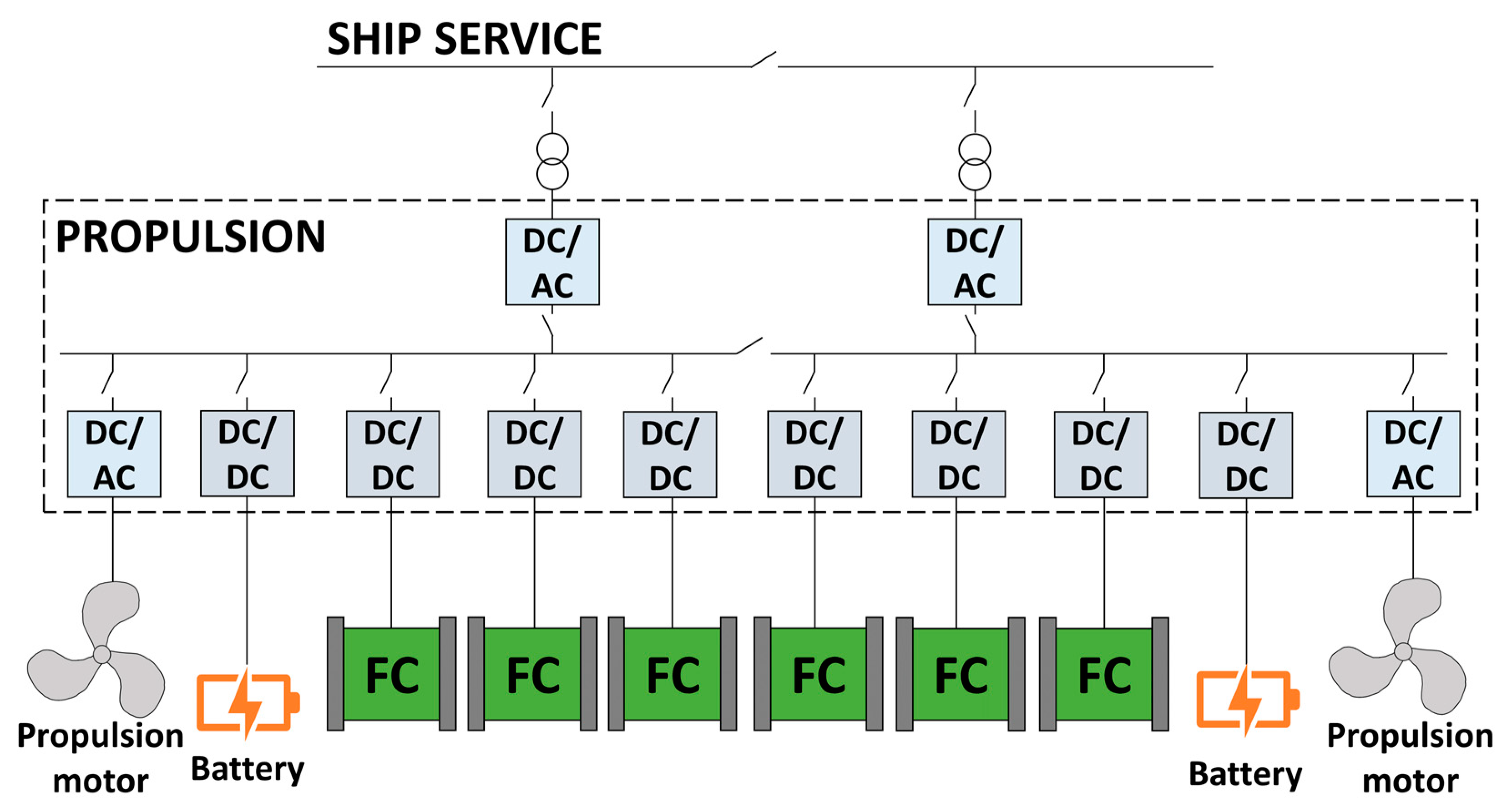
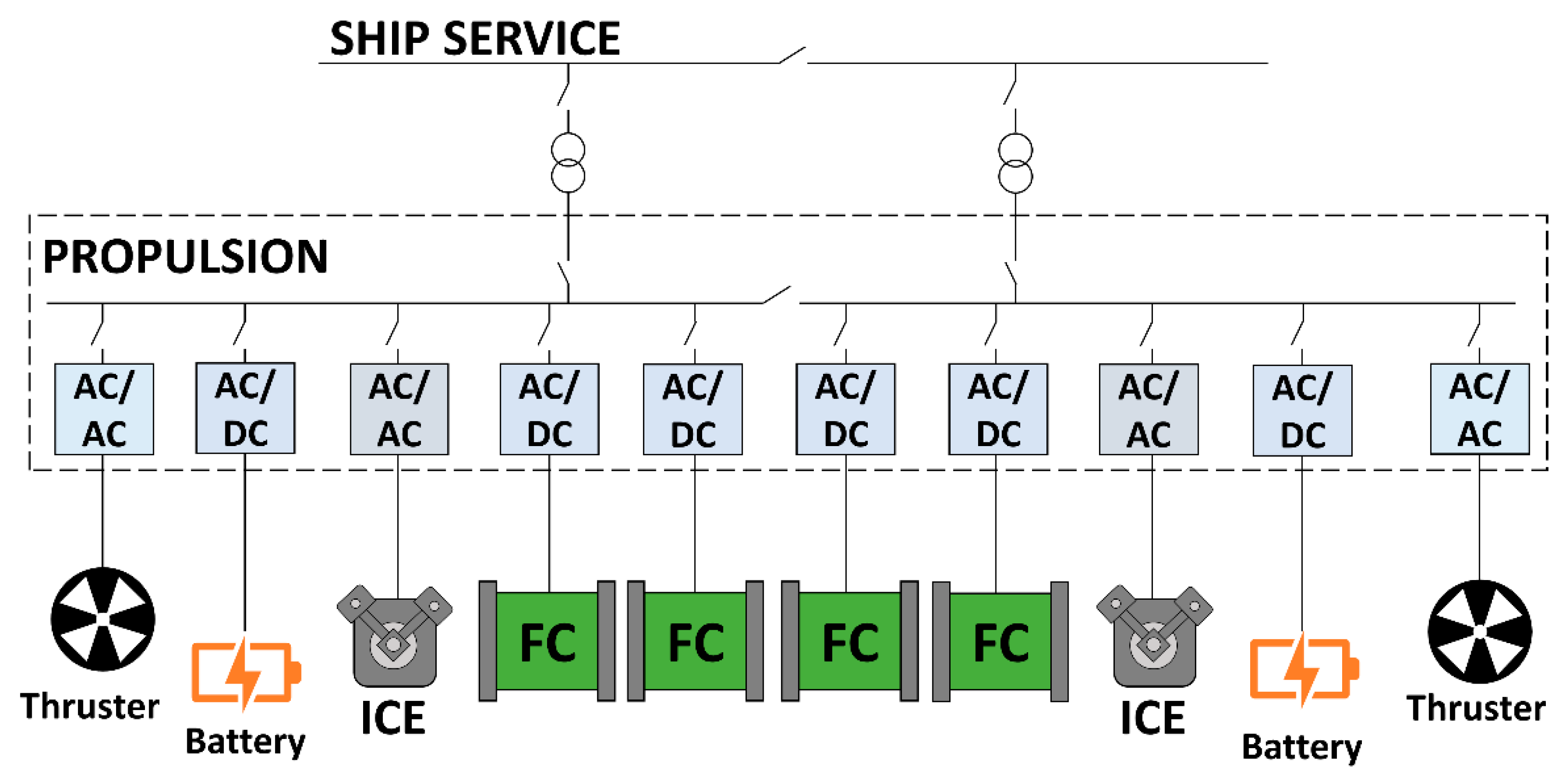
4.2. Hydrogen Utilization on Board

The power needed for propulsion and the onboard energy supply can be generated from LH2 through:
  • Internal combustion engines (ICEs).
  • Fuel cells (FCs).
  • Hybrid (batteries and fuel cells).
  • Gas or steam turbines.
Most of the abovementioned studies consider installing an FC system [105,109,135] or a hybrid (batteries and fuel cells) system [99,103,104,106,112,132,133] to generate the power required by the ship to maximize its efficiency. A few studies took into account the utilization of different types of fuels on board, such as hydrogen and diesel employed in FCs and diesel generators, respectively [108,110,111,112,125,126,128,131], or hydrogen and natural gas which power FCs and DFDE engines, respectively [116]. On the other hand, only Kawasaki Heavy Industries [115] designed a ship where LH2 is supplied to gas engines, while Alkhaledi et al. [117] proposed using hydrogen in a combined-cycle gas turbine. The schematics of the hybrid (fuel cells and batteries) system and the FCs and ICEs system can be found in Figure 3 and Figure 4, respectively. These figures are reported as examples of how the fuel cells can be integrated with the power system on board. It can be noticed that the management of electricity becomes critical in these setups. This is demonstrated by the elevated number of devices necessary either to adjust the voltage of the direct and alternative electric currents (DC/DC and AC/AC converters) or to convert it from direct to alternative current or vice versa (DC/AC or AC/DC). In particular, the switchboard works with direct current when batteries and FCs are used (Figure 3), while alternative current will flow in it when ICEs are installed (Figure 4). This is justified by the fact that batteries and FCs generate direct current and ICE the alternative one.
The LH2 storage components are common to all the systems described heretofore. In fact, a very well thermally insulated tank (see Section 3.1) is required to store LH2, as well as an evaporator and heat exchangers, since FC, ICE, and gas turbines necessitate gaseous hydrogen at a temperature close to the atmospheric one. All the pieces of equipment which will be in contact with LH2 (tank, piping, evaporator, heat exchangers, etc.) must be made of appropriate materials (see Section 3.1.1). Despite this representing a technological and economic challenge, the cold provided by the LH2 can and should be exploited for onboard purposes. For instance, additional electricity can be generated by means of a semi-closed recuperative gas turbine cycle with either nitrogen or helium as working fluid, and LH2 as a cold heat sink, as proposed by Zhang and Lior [149]. Otherwise, the cold can be exploited for service utilities such as refrigeration and air conditioning purposes.

4.3. Codes, Standards and Regulations

As previously mentioned, codes and standards for the use of hydrogen in the maritime sector have not been developed yet, neither to design LH2 vessels nor the bunkering facilities. This represents a bottleneck for the implementation of hydrogen as a fuel on board ships. In many feasibility studies presented in Section 4.1.1 of this paper, the authors proposed adapting regulations and technologies developed for LNG to LH2 [106,107,108].

4.3.1. LH2 Vessel Design

Different regulations must be followed when designing an LH2 vessel. The codes must be chosen according to the type of vessel. For instance, Pratt and Klebanoff [106] selected the most suitable regulations for the design of a small passenger vessel for the feasibility study on the SF BREEZE ferry. In particular, the authors used as base regulation the 46 Code of Federal Regulations (CFR) Subchapter T—Small Passenger Vessels. On the other hand, the main code applied for the implementation of hydrogen technologies has been the 2015 international code of safety for ships using gases or other low-flashpoint fuels (IMO MSC 95/22/Add.1), known as the IGF Code. This code has been widely adopted to design ships both with storage of compressed gaseous and cryogenic liquid hydrogen in [106,107,108,113]. The main limitations of the IGF code are that it was developed for LNG and for vessels that belong to the safety of life at sea (SOLAS) category. This latter is an international maritime treaty for merchant vessels, thus not applicable to small passenger ships operating in inland waters. After a thorough comparison of the chemical and physical properties of LNG and LH2, Pratt and Klebanoff [106] concluded that these two substances have enough in common that it is appropriate to employ the IGF code as a regulatory starting point for the design of an LH2 ferry.
Other standards selected by Pratt and Klebanoff [106] were: IMO CCC 2/3/1 (IGF Code with Fuel Cell Additions), ASME B31.12 Hydrogen Piping and Pipelines, ANSI/CSA America FC1-2004 Stationary Fuel Cell Power Systems, IEC 62282-2-100:2020—Fuel Cell Technologies—Part 2-100: Fuel Cell Modules—Safety, and IEC 62282-3-100:2019—Fuel Cell Technologies—Part 3-100: Stationary Fuel Cell Power Systems—Safety. It can be noticed that these codes and standards are not specifically written for liquid hydrogen. On the other hand, the IMO adopted in 2016 the resolution MSC.420(97) for the international code of the construction and equipment of ships carrying liquefied gases in bulk (IGC Code), with the title “Interim recommendations for carriage of liquefied hydrogen bulk”. Both Kamiya et al. [115] and Alkhaledi et al. [117] adhered to the IGC code to design the LH2 tankers described in Section 4.1.1. Based on these IMO interim recommendations, ClassNK published the guidelines for liquefied hydrogen carriers for the safe construction and operation of LH2 carriers [150]. The ClassNK guidelines were followed by Jeong et al. [116] to carry out the analysis of an LNG-LH2 hybrid propulsion system for an LNG carrier.

4.3.2. LH2 Bunkering Facilities

As for the design of LH2 ships, regulations, codes, and standards for the bunkering of LH2 have not been developed yet. However, a few regulations for LH2 transfer could be adapted for bunkering. One example of regulation is the Safety of storage, handling, and distribution of liquid hydrogen, Doc 06/19, written by the European Industrial Gases Association (EIGA) [138]. Pratt and Klebanoff [106] combined regulations and guidelines with technical knowledge of hydrogen systems to define a regulatory approach for LH2 bunkering. In particular, these authors considered several documents written by the US CFR, the United States Coast Guard (USCG), the American Bureau of Shipping (ABS), DNV-GL, and the ISO. Additional details on these regulations can be found in [106]. Furthermore, the authors suggested integrating or referring to existing regulations developed for hydrogen such as ASME B31.12 (Hydrogen Piping and Pipelines) and NFPA 2 (Hydrogen Technologies Code) in future LH2 bunkering standards. Similarly, DNV-GL highlighted the gap in the IGF code regarding bunkering of both gaseous and liquid hydrogen and explicitly stated that bunkering rules for LH2 do not exist [151]. Therefore, DNV-GL suggested exploiting the bunkering procedures for LNG and the experience gained in transferring LH2 onshore to determine the first requirements for LH2 bunkering. Additionally, quantitative risk analyses are required to establish the rules and LH2 bunkering procedures. Another example of a feasibility study for LH2 bunkering is provided in the recent DNV report previously mentioned [139]. In this case, the aim was to identify hydrogen bunkering scenarios for inland navigation vessels.

4.4. Safety

The regulations described in Section 4.3 such as the IGF code address several safety aspects in the implementation of LNG in the maritime sector. For this reason, LH2 is often compared with LNG to comprehend the applicability of the available regulations to LH2 technologies. Pratt and Klebanoff [106] performed a thorough comparison between LNG and LH2 by focusing on their physical properties and safety aspects. A description of hydrogen chemical and physical properties that may represent a safety concern can be found in [8]. The authors considered both hydrogen permeation and embrittlement to investigate potential faults that can lead to the loss of integrity of hydrogen storage equipment. Hence, spills of fuel were assumed as possible critical events during an accident based on the experiments carried out on LH2 releases in the past. LH2 leakages and spills could disperse more slowly than CGH2 losses due to the higher density, hence these scenarios require the development of dedicated release models and consequences analysis [152]. Moreover, several phenomena that might occur after the loss of containment of LNG and LH2 storage equipment were analyzed. A comprehensive description of different types of ignition (spontaneous, explicit), ignition sources (weak (thermal), strong (shock wave)), and combustion properties were provided. Other consequences of failure considered in [106] were fires (jet and pool), explosions (deflagration and detonation), and the deflagration to detonation transition (DDT). A DDT is an explosion that evolves from a deflagration, i.e., the flame front speed is lower than the speed of sound, to a detonation (flame front speed > sound speed). Both hydrogen and natural gas can undergo DDT, but hydrogen is more susceptible to DDT [106]. For a DDT to occur, the hydrogen concentration in air must be higher than 12% in volume, a weak ignition source would be enough, and obstacles responsible for enhancing the generation of turbulences, thus the flame acceleration, should be present. More precisely, DDT may occur at a certain distance in confinement even without obstacles if the hydrogen concentration reaches 30%vol in air (close to stoichiometric ratio) [153]. On the other hand, a hydrogen concentration of 12%vol in air would be enough to attain DDT in the presence of obstacles. The outcomes of the comparison of LNG and LH2 were that LH2 evaporates more easily, and its spills are smaller and shorter in time. Even though it is well known that hydrogen has a wider flammability range (4–75%vol in air) than LNG (5.3–15%vol in air for methane), their vapors ignite with weak thermal ignition sources. Furthermore, both hydrogen and natural gas can directly explode if their concentration is in their flammability range in enclosure spaces by means of a strong (e.g., shock wave) ignition source. Despite the fact that hydrogen flame temperature can be higher than the natural gas one, LH2 fires last less long than LNG ones thanks to the higher flame speed. In addition, LH2 fires have a lower thermal radiation that is largely absorbed by the air humidity. Hydrogen embrittlement does not manifest for LNG technologies, and it can be solved for hydrogen by selecting appropriate materials (e.g., 304 and 316 stainless steel) during the design phase of equipment as already explained in Section 3.1.1. In the case of LH2, low-temperature embrittlement must be considered as well. For this reason, carbon steels must be avoided since they are prone to this phenomenon (see Section 3.1.1). Finally, Pratt and Klebanoff [106] concluded that similar risks can arise from the utilization of both LH2 and LNG in the maritime sector since their physical and combustion properties are similar.
The previous comparison considered the fire and explosion phenomena already investigated for LNG and LH2 and attempted to determine the probability and consequences of spills on board. This is a quite complex task to solve since the maritime sector is a new application for LH2, thus an emerging technology from which emerging risks might arise. For instance, it is not possible to determine the probabilities of failure of certain critical events because accident databases do not exist yet. Moreover, the probability and consequences of some phenomena were not taken into account. Two physical explosions, namely boiling liquid expanding vapor explosion (BLEVE) and rapid phase transition (RPT), might happen after the accidental release of cryogenic fluids, even non-flammable ones. BLEVE is a phenomenon that can occur after the catastrophic rupture of a vessel containing a superheated liquid. The explosion is produced by the expansion of the compressed gaseous phase and the flashing of a fraction of the liquid. Beyond the blast wave and the throwing of fragments (e.g., tank debris) in the surrounding area, a fireball can develop if the substance is flammable and is ignited by an external source. On the other hand, RPT is a well-known phenomenon for LNG and may manifest when the cryogenic fuel is released onto or into the water due to the sudden heat transfer and flashing of the cryogenic liquid into vapor. Therefore, the explosion is generated without any combustion or chemical reaction. It is still unclear if RPT is a characteristic phenomenon for LH2, thus experimental tests on LH2 release onto water such as the ones carried out during the Norwegian project SH2IFT [154,155] are required. In [155], it has been demonstrated that LH2 tanks have excellent performance when engulfed in propane fires since the resistance time was between 1 and 4 h depending on the type of insulation (vacuum jacket filled either with perlite or MLI). Additional details on the BLEVE and RPT phenomena and their modelling for LH2 can be found in [156,157,158,159,160,161,162,163,164,165,166]. Finally, safety risks related to the condensation of air components (nitrogen and oxygen) may derive from LH2 technologies [167]. In fact, in the case of an LH2 release, both nitrogen and oxygen can condensate or even solidify due to the extremely low temperature of LH2. This cannot happen for LNG since its boiling temperature at atmospheric pressure is higher than that of air. These observations are made to note that many safety aspects must not be neglected during the implementation of LH2 technologies in the maritime sector.
All these considerations are necessary for the determination of hazardous zones. The IGF code described in Section 4.3 provides indications to establish appropriate hazardous distances (e.g., from pressure relief valve outlets and air inlets) [106]. Different regulations require carrying out a detailed risk assessment to establish the separation distances. In the case of the SF-BREEZE high-speed ferry, the Elliott Bay Design Group (EBDG) performed a preliminary risk assessment for the feasibility study [106]. Other examples of the determination of hazardous areas for LH2 vessels are the research vessels Zero-V [107] and Robert Gordon Sproul [108]. These can be reduced by implementing appropriate and effective safety barriers such as fire protection and water spray systems. Finally, the general safety recommendations to consider during the implementation of LH2 technologies on board ships are the following: adopt appropriate measures to avoid fuel leaks, minimize ignition sources and confined spaces, supply adequate ventilation in enclosure, and monitor these spaces to keep the fuel concentration below 0.4%vol in air to avoid any combustion. It is also critical and fundamental to keep in mind that emerging risks might arise, and different phenomena must be still investigated further for LH2.

5. Challenges for the Implementation of Liquid Hydrogen in the Maritime Sector

In the previous sections, past works on the implementation of LH2 technologies in the transport sector were presented. The studies focused on maritime applications demonstrated the feasibility of using and storing LH2 on board. In the following, the findings of the works previously described are discussed by considering the challenges and bottlenecks for deployment of LH2 in the maritime sector.
Environmental aspects must be always considered even when using hydrogen on board vessels. As demonstrated in Section 2, hydrogen has virtually no emissions when used to generate electricity on ships, but the environmental impacts of its entire lifecycle can be very different depending on how the hydrogen is produced and even transported. For complete decarbonization of the maritime sector, black (or brown), gray, blue, and yellow hydrogen must be avoided. Moreover, both scheduled (venting) and unintentional (leakages) releases of hydrogen into the atmosphere must be limited to prevent the intrinsic indirect GHG effect of hydrogen. Furthermore, the release of hydrogen can have consequences in terms of costs and safety since precious fuel is lost and flammable atmospheres are created during releases.
Many technical challenges are met with when storing LH2 both in the harbors and on board vessels due to the cryogenic nature of this substance. Extremely well-insulated (e.g., vacuumed MLI) storage devices (tanks, pipes, valves, etc.) must be employed to keep LH2 in the liquid phase, i.e., at a temperature close to its boiling point. This means that appropriate tanks must be built to store LH2 both onshore (ports) and on board ships. The current challenge is represented by the low availability of this type of components since few suppliers exist worldwide. Therefore, this low availability has a negative implication for the cost of these devices. Moreover, the cryogenic nature of LH2 affects the BOG formation with consequent venting. This process is needed to keep the pressure of the LH2 tank within a safety threshold and avoid its rupture. As previously mentioned, the release of a flammable gas has a negative influence on environment, costs, and safety. One solution for onshore storage systems (e.g., in ports) would be to adopt an IRAS system such as the one developed by NASA where the internal temperature of the LH2 tank is kept close to the boiling point thanks to a refrigerating system. In this fashion, hydrogen venting is avoided. It was demonstrated that the cost of the electricity required to power the IRAS is lower than the cost of dispersing hydrogen in the atmosphere [56,57]. In addition, the negative environmental impact represented by the indirect GHG effect, as well as the safety concerns, are avoided. Another solution would be to collect the BOG in an additional pressurized tank capable of bearing high pressures as currently carried out at the only LH2 bunkering facility in Kobe, Japan. On the other hand, neither an IRAS system nor additional tanks can be installed on board ships. In this case, the BOG can be used to generate the power needed on board, for instance by feeding the FC system. Therefore, the release of hydrogen would be limited to accident scenarios (low-probability events). Nevertheless, it has been demonstrated that LH2 tanks seem to perform very well in accident scenarios such as fire engulfment. During the tests carried out in [155], the resistance time of the tank to a propane fire was quite long (between 1 and 4 h) depending on the type of insulation (perlite or MLI). Another considerable challenge is the management of electricity on board. The amount of generated electricity would be higher compared to conventional ship designs where ICEs are used. The electricity management must be carried out efficiently and safely. On the other hand, electricity management should not be a relevant issue onboard LH2 tankers propelled by diesel engines such as the existing Suiso Frontier.
The utilization of cryogenic equipment represents a challenge in terms of materials, as described in Section 3.1.1. Only materials for cryogenic applications must be employed, having a negative consequence in terms of costs. Moreover, these materials must be suitable for the marine environment as well, thus capable of resisting corrosion. The advantage of the cryogenic equipment is that it is double walled to increase the thermal insulation performance. This means that the cryogenic materials can be used to build the internal wall (e.g., inner tank), while the external one can be made of a material suitable for the marine environment. In addition, the behavior of many materials for cryogenic applications must be investigated further to assess their performances when exposed to fatigue cycles. The integrity of hydrogen equipment is critical to avoid loss of containment which may lead to severe accidents. Effective inspection and maintenance methodologies must be developed for hydrogen technologies deployed in new applications, as discussed in [168].
The lack of infrastructure is one of the most critical bottlenecks for the deployment of LH2 in the maritime sector. Again, all the aspects previously discussed (technical, economic, material, and safety) are also relevant for bunkering facilities. One possibility would be to retrofit existing infrastructures. However, this option must be assessed for each harbor and understood if it can be advantageous in terms of costs, while a high safety level must be guaranteed. Despite the fact that hydrogen technology costs were not analyzed in this study, the economic aspect is another critical bottleneck for the deployment of LH2 in the maritime sector. This is a common limitation for most emerging technologies when large-scale production has not commenced yet. High costs are expected during the transition phase to construct the necessary infrastructure or retrofit existing ones, and to design and build LH2 vessels composed of expensive devices such as cryogenic equipment, fuel cells, and batteries.
A broad analysis of the safety aspects of LH2 technologies employed in the maritime sector was provided in Section 4.4. It has been demonstrated that hydrogen has many properties (e.g., high buoyancy at atmospheric temperature, low-radiation flame, high-speed flame, non-toxic) that make it a safer fuel compared to the traditional ones, and other characteristics that can generate safety concerns (e.g., wide flammability range, low minimum ignition energy, detection issues). Therefore, the design of new vehicles powered by LH2 must be optimized to exploit the safe hydrogen properties and prevent accidents that can be initiated by hazardous hydrogen properties. The safety of humans, structure integrity, as well as environmental issues, must be central when designing ships and ports where LH2 will be employed. Depending on the type of ship, different persons (e.g., workers, ship crew, passengers) might be involved in potential accidents as well as other vehicles (e.g., cars, buses, trucks). Thus, each situation must be analyzed carefully and differently depending on the application requirements. Furthermore, atypical accident scenarios (e.g., BLEVE and RPT) that are often neglected by conventional risk assessment techniques due to their low probabilities must be investigated for an emerging technology. The research in terms of safety will aid the development of new regulations that will boost the deployment of LH2 technologies in the maritime field.
As a result of the findings of this study, one of the main suggestions is that the future design of both LH2 ships and infrastructures must be optimized and tailored based on the harbor and ship needs. It must be assessed if LH2 is the best solution for each application. For instance, most of the studies previously described have estimated that LH2 is best suited for long-range ships and where large amounts of hydrogen must be transported. Furthermore, the requirements for an LH2 tanker (hydrogen amount, power requirement, etc.) would be quite different than for an LH2 ferry. In addition, guidelines, recommendations, codes, and standards for the design of LH2 ships and LH2 distribution and storage infrastructures, and for LH2 handling on board as well as in the harbor, have not been developed yet but are necessary for the safe and efficient implementation of LH2 technologies in the maritime sector. Future works are required on each aspect analyzed in this study (technical, economic, material, safety), as previously described in this section.

6. Conclusions

An overview of the utilization of LH2 as a fuel in the transport sector was provided in this paper. All the most critical aspects were considered including environmental issues (CO2 equivalent emissions during hydrogen production), feasibility and technical challenges, and safety. The different hydrogen colors were defined to provide a complete reference that is missing in the literature. Moreover, it has been demonstrated that the employment of hydrogen as a fuel in transportation can tackle environmental issues only if its carbon footprint is minimized. An extensive overview of the employment of LH2 in the transport sector has been provided. Previous experiences demonstrate that LH2 can be used as a fuel in all types of transportation: road, aerospace and aviation, railway, and maritime. The focus here has been placed on the maritime sector since LH2 is preferred over compressed gaseous hydrogen for long-range voyages of large ships. The technical, economic, regulatory, and safety barriers were highlighted and discussed. LH2 can substitute fossil fuels in the maritime sector only if the abovementioned bottlenecks are removed. In particular, the costs of LH2 and the components required to handle and store it must be reduced, and the lack of infrastructure overcome. Many suggestions for future studies from technical and safety perspectives were provided. The main suggestion given by the authors is that the design of LH2 technologies must be optimized for each application (e.g., type of ship, size of harbor). Finally, it must be demonstrated that LH2-powered ships are as safe as or even safer than conventional ships in order to stimulate the development of appropriate regulations and promote the deployment of LH2 technologies in the maritime field.

Author Contributions

Conceptualization, F.U.; methodology, F.U.; formal analysis, F.U. and A.C.; investigation, F.U. and A.C.; writing—original draft preparation, F.U., A.C. and R.T.; writing—review and editing, F.U., A.C., and R.T.; visualization, F.U. and A.C.; supervision, R.T. All authors have read and agreed to the published version of the manuscript.

Funding

This research received no external funding.

Institutional Review Board Statement

Not applicable.

Informed Consent Statement

Not applicable.

Data Availability Statement

Not applicable.

Conflicts of Interest

The authors declare no conflict of interest.

References

  1. European Commission. A European Green Deal. Available online: https://ec.europa.eu/info/strategy/priorities-2019-2024/european-green-deal_en (accessed on 16 August 2022).
  2. European Commission. REPowerEU: A Plan to Rapidly Reduce Dependence on Russian Fossil Fuels and Fast Forward the Green Transition. Available online: https://ec.europa.eu/commission/presscorner/detail/en/IP_22_3131 (accessed on 16 August 2022).
  3. NIST. NIST Chemistry WebBook 69. Available online: https://webbook.nist.gov/chemistry/ (accessed on 16 August 2022).
  4. Airbus. Airbus Reveals New Zero-Emission Concept Aircraft. Available online: https://www.airbus.com/en/newsroom/press-releases/2020-09-airbus-reveals-new-zero-emission-concept-aircraft (accessed on 16 August 2022).
  5. International Council on Clean Transportation (ICCT). VISION 2050, A Strategy to Decarbonize the Global Transport Sector by Mid-Century. 2020. Available online: https://theicct.org/wp-content/uploads/2021/06/ICCT_Vision2050_sept2020.pdf (accessed on 16 August 2022).
  6. Taccani, R.; Ustolin, F.; Zuliani, N.; Pinamonti, P.; Pietra, A. Fuel Cells and Shipping Emissions Mitigation. In Proceedings of the NAV International Conference on Ship and Shipping Research, Trieste, Italy, 20–22 June 2018. [Google Scholar]
  7. U.S. Energy Information Administration. Hydrogen Explained–Production of Hydrogen. Available online: https://www.eia.gov/energyexplained/hydrogen/production-of-hydrogen.php (accessed on 16 August 2022).
  8. Ustolin, F.; Paltrinieri, N.; Berto, F. Loss of Integrity of Hydrogen Technologies: A Critical Review. Int. J. Hydrogen Energy 2020, 45, 23809–23840. [Google Scholar] [CrossRef]
  9. International Energy Agency (IEA). Global Hydrogen Review 2021; IEA: Paris, France, 2021; Available online: https://www.iea.org/reports/global-hydrogen-review-2021 (accessed on 16 August 2022).
  10. Ajanovic, A.; Sayer, M.; Haas, R. The Economics and the Environmental Benignity of Different Colors of Hydrogen. Int. J. Hydrogen Energy 2022, 47, 24136–24154. [Google Scholar] [CrossRef]
  11. Recharge–NHST Media Group Green Hydrogen Now Cheaper to Produce than Grey H2 across Europe Due to High Fossil Gas Prices. Available online: https://www.rechargenews.com/energy-transition/green-hydrogen-now-cheaper-to-produce-than-grey-h2-across-europe-due-to-high-fossil-gas-prices/2-1-1098104 (accessed on 16 August 2022).
  12. Dodgshun, J. Hydrogen: Clearing Up the Colours. Available online: https://www.enapter.com/newsroom/hydrogen-clearing-up-the-colours (accessed on 16 August 2022).
  13. Droege, T. Williams Companies—What Are the Colors of Hydrogen? Available online: https://www.williams.com/2021/04/23/what-are-the-colors-of-hydrogen/ (accessed on 16 August 2022).
  14. National Grid. The Hydrogen Colour Spectrum. Available online: https://www.nationalgrid.com/stories/energy-explained/hydrogen-colour-spectrum (accessed on 16 August 2022).
  15. Bridges, T.; Merzian, R. Hydrogen and Climate: Trojan Horse or Golden Goose?: Request for Input—National Hydrogen Strategy; The Australia Institute: Canberra, Australia, 2019. [Google Scholar]
  16. Midilli, A.; Kucuk, H.; Topal, M.E.; Akbulut, U.; Dincer, I. A Comprehensive Review on Hydrogen Production from Coal Gasification: Challenges and Opportunities. Int. J. Hydrogen Energy 2021, 46, 25385–25412. [Google Scholar] [CrossRef]
  17. Li, J.; Cheng, W. Comparative Life Cycle Energy Consumption, Carbon Emissions and Economic Costs of Hydrogen Production from Coke Oven Gas and Coal Gasification. Int. J. Hydrogen Energy 2020, 45, 27979–27993. [Google Scholar] [CrossRef]
  18. Li, G.; Cui, P.; Wang, Y.; Liu, Z.; Zhu, Z.; Yang, S. Life Cycle Energy Consumption and GHG Emissions of Biomass-to-Hydrogen Process in Comparison with Coal-to-Hydrogen Process. Energy 2020, 191, 116588. [Google Scholar] [CrossRef]
  19. Postels, S.; Abánades, A.; von der Assen, N.; Rathnam, R.K.; Stückrad, S.; Bardow, A. Life Cycle Assessment of Hydrogen Production by Thermal Cracking of Methane Based on Liquid-Metal Technology. Int. J. Hydrogen Energy 2016, 41, 23204–23212. [Google Scholar] [CrossRef]
  20. Howarth, R.W.; Jacobson, M.Z. How Green Is Blue Hydrogen? Energy Sci. Eng. 2021, 9, 1676–1687. [Google Scholar] [CrossRef]
  21. Siddiqui, O.; Dincer, I. A Well to Pump Life Cycle Environmental Impact Assessment of Some Hydrogen Production Routes. Int. J. Hydrogen Energy 2019, 44, 5773–5786. [Google Scholar] [CrossRef]
  22. Oni, A.O.; Anaya, K.; Giwa, T.; Di Lullo, G.; Kumar, A. Comparative Assessment of Blue Hydrogen from Steam Methane Reforming, Autothermal Reforming, and Natural Gas Decomposition Technologies for Natural Gas-Producing Regions. Energy Convers. Manag. 2022, 254, 115245. [Google Scholar] [CrossRef]
  23. Antonini, C.; Treyer, K.; Streb, A.; van der Spek, M.; Bauer, C.; Mazzotti, M. Hydrogen Production from Natural Gas and Biomethane with Carbon Capture and Storage—A Techno-Environmental Analysis. Sustain. Energy Fuels 2020, 4, 2967. [Google Scholar] [CrossRef] [Green Version]
  24. Romano, M.C.; Antonini, C.; Bardow, A.; Bertsch, V.; Brandon, N.P.; Brouwer, J.; Campanari, S.; Crema, L.; Dodds, P.E.; Gardarsdottir, S.; et al. Comment on “How Green Is Blue Hydrogen?”. Energy Sci. Eng. 2022, 10, 1944–1954. [Google Scholar] [CrossRef]
  25. Amin, A.M.; Croiset, E.; Epling, W. Review of Methane Catalytic Cracking for Hydrogen Production. Int. J. Hydrogen Energy 2011, 36, 2904–2935. [Google Scholar] [CrossRef]
  26. Schneider, S.; Bajohr, S.; Graf, F.; Kolb, T. State of the Art of Hydrogen Production via Pyrolysis of Natural Gas. ChemBioEng Rev. 2020, 7, 150–158. [Google Scholar] [CrossRef]
  27. Leal Pérez, B.J.; Medrano Jiménez, J.A.; Bhardwaj, R.; Goetheer, E.; van Sint Annaland, M.; Gallucci, F. Methane Pyrolysis in a Molten Gallium Bubble Column Reactor for Sustainable Hydrogen Production: Proof of Concept & Techno-Economic Assessment. Int. J. Hydrogen Energy 2021, 46, 4917–4935. [Google Scholar] [CrossRef]
  28. Dufour, J.; Serrano, D.P.; Gálvez, J.L.; González, A.; Soria, E.; Fierro, J.L.G. Life Cycle Assessment of Alternatives for Hydrogen Production from Renewable and Fossil Sources. Int. J. Hydrogen Energy 2012, 37, 1173–1183. [Google Scholar] [CrossRef]
  29. Cetinkaya, E.; Dincer, I.; Naterer, G.F. Life Cycle Assessment of Various Hydrogen Production Methods. Int. J. Hydrogen Energy 2012, 37, 2071–2080. [Google Scholar] [CrossRef]
  30. Ghandehariun, S.; Kumar, A. Life Cycle Assessment of Wind-Based Hydrogen Production in Western Canada. Int. J. Hydrogen Energy 2016, 41, 9696–9704. [Google Scholar] [CrossRef]
  31. Valente, A.; Iribarren, D.; Dufour, J. Harmonising Methodological Choices in Life Cycle Assessment of Hydrogen: A Focus on Acidification and Renewable Hydrogen. Int. J. Hydrogen Energy 2019, 44, 19426–19433. [Google Scholar] [CrossRef]
  32. Dincer, I. Green Methods for Hydrogen Production. Int. J. Hydrogen Energy 2012, 37, 1954–1971. [Google Scholar] [CrossRef]
  33. Noussan, M.; Raimondi, P.P.; Scita, R.; Hafner, M. The Role of Green and Blue Hydrogen in the Energy Transition—A Technological and Geopolitical Perspective. Sustainability 2021, 13, 298. [Google Scholar] [CrossRef]
  34. IEA. Hydrogen 2021. Available online: https://www.iea.org/reports/hydrogen (accessed on 16 August 2022).
  35. Wulf, C.; Kaltschmitt, M. Life Cycle Assessment of Hydrogen Supply Chain with Special Attention on Hydrogen Refuelling Stations. Int. J. Hydrogen Energy 2012, 37, 16711–16721. [Google Scholar] [CrossRef]
  36. World Economic Forum. Grey, Blue, Green—Why Are There So Many Colours of Hydrogen? Available online: https://www.weforum.org/agenda/2021/07/clean-energy-green-hydrogen/ (accessed on 16 August 2022).
  37. Yu, M.; Wang, K.; Vredenburg, H. Insights into Low-Carbon Hydrogen Production Methods: Green, Blue and Aqua Hydrogen. Int. J. Hydrogen Energy 2021, 46, 21261–21273. [Google Scholar] [CrossRef]
  38. Boretti, A. White Is the Color of Hydrogen from Concentrated Solar Energy and Thermochemical Water Splitting Cycles. Int. J. Hydrogen Energy 2021, 46, 20790–20791. [Google Scholar] [CrossRef]
  39. Boretti, A. There Are Hydrogen Production Pathways with Better than Green Hydrogen Economic and Environmental Costs. Int. J. Hydrogen Energy 2021, 46, 23988–23995. [Google Scholar] [CrossRef]
  40. Energy Observer. What Potential for Natural Hydrogen? Available online: https://www.energy-observer.org/resources/natural-hydrogen (accessed on 16 August 2022).
  41. Rahn, T.; Eiler, J.M.; Boering, K.A.; Wennberg, P.O.; McCarthy, M.C.; Tyler, S.; Schauffler, S.; Donnelly, S.; Atlas, E. Extreme Deuterium Enrichment in Stratospheric Hydrogen and the Global Atmospheric Budget of H2. Nature 2003, 424, 918–921. [Google Scholar] [CrossRef]
  42. Derwent, R.G.; Stevenson, D.S.; Utembe, S.R.; Jenkin, M.E.; Khan, A.H.; Shallcross, D.E. Global Modelling Studies of Hydrogen and Its Isotopomers Using STOCHEM-CRI: Likely Radiative Forcing Consequences of a Future Hydrogen Economy. Int. J. Hydrogen Energy 2020, 45, 9211–9221. [Google Scholar] [CrossRef]
  43. Paulot, F.; Paynter, D.; Naik, V.; Malyshev, S.; Menzel, R.; Horowitz, L.W. Global Modeling of Hydrogen Using GFDL-AM4.1: Sensitivity of Soil Removal and Radiative Forcing. Int. J. Hydrogen Energy 2021, 46, 13446–13460. [Google Scholar] [CrossRef]
  44. Field, R.A.; Derwent, R.G. Global Warming Consequences of Replacing Natural Gas with Hydrogen in the Domestic Energy Sectors of Future Low-Carbon Economies in the United Kingdom and the United States of America. Int. J. Hydrogen Energy 2021, 46, 30190–30203. [Google Scholar] [CrossRef]
  45. Ocko, I.B.; Hamburg, S.P. Climate Consequences of Hydrogen Leakage. Atmos. Chem. Phys. Discuss. 2022, 22, 9349–9368. [Google Scholar] [CrossRef]
  46. Peschka, W. Liquid Hydrogen—Fuel of the Future, 1st ed.; Springer: Wien, Austria, 1992; ISBN 9783709191286. [Google Scholar]
  47. Zhuzhgov, A.V.; Krivoruchko, O.P.; Isupova, L.A.; Mart’yanov, O.N.; Parmon, V.N. Low-Temperature Conversion of Ortho-Hydrogen into Liquid Para-Hydrogen: Process and Catalysts. Review. Catal. Ind. 2018, 10, 9–19. [Google Scholar] [CrossRef]
  48. Bracha, M.; Lorenz, G.; Patzelt, A.; Wanner, M. Large-Scale Hydrogen Liquefaction in Germany. Int. J. Hydrogen Energy 1994, 19, 53–59. [Google Scholar] [CrossRef]
  49. DOE. Energy Requirements for Hydrogen Gas Compression and Liquefaction as Related to Vehicle Storage Needs; DOE: Washington, DC, USA, 2009.
  50. Verfondern, K. Safety Considerations on Liquid Hydrogen; Forschungszentrum Jülich GmbH: Jülich, Germany, 2008. [Google Scholar]
  51. Tzimas, E.; Filiou, C.; Peteves, S.D.; Veyret, J.B. Hydrogen Storage: State-of-the-Art and Future Perspective; European Commission: Petten, The Netherlands, 2003; ISBN 9289469501. [Google Scholar]
  52. Krainz, G.; Bartlok, G.; Bodner, P.; Casapicola, P.; Doeller, C.; Hofmeister, F.; Neubacher, E.; Zieger, A. Development of Automotive Liquid Hydrogen Storage Systems. AIP Conf. Proc. 2004, 710, 35–40. [Google Scholar]
  53. Michel, F.; Fieseler, H.; Allidieres, L. Liquid Hydrogen Technologies for Mobile Use Friedel. In Proceedings of the 16th World Hydrogen Energy Conference WHEC, Zaragoza, Spain, 13–16 June 2006; pp. 694–702. [Google Scholar]
  54. Müller, C.; Fürst, S.; von Klitzing, W. Hydrogen Safety: New Challenges Based on BMW Hydrogen 7. In Proceedings of the Second International Conference on Hydrogen Safety, San Sebastian, Spain, 11–13 September 2007. [Google Scholar]
  55. NASA; Sempsrott, D. Kennedy Plays Critical Role in Large-Scale Liquid Hydrogen Tank Development. Available online: https://www.nasa.gov/feature/kennedy-plays-critical-role-in-large-scale-liquid-hydrogen-tank-development (accessed on 16 August 2022).
  56. Notardonato, W.U.; Swanger, A.M.; Fesmire, J.E.; Jumper, K.M.; Johnson, W.L.; Tomsik, T.M. Zero Boil-off Methods for Large-Scale Liquid Hydrogen Tanks Using Integrated Refrigeration and Storage. In Proceedings of the IOP Conference Series: Materials Science and Engineering, Madison, WI, USA, 9–13 July 2017; Institute of Physics Publishing: Bristol, UK, 2017; Volume 278, p. 012012. [Google Scholar]
  57. NASA; Granath, B. Innovative Liquid Hydrogen Storage to Support Space Launch System. Available online: https://www.nasa.gov/feature/innovative-liquid-hydrogen-storage-to-support-space-launch-system (accessed on 16 August 2022).
  58. Ehrhart, B.D.; Bran Anleu, G.; Mohmand, J.A.; Baird, A.R.; Klebanoff, L.E. Refueling Infrastructure Scoping and Feasibility Assessment for Hydrogen Rail Applications; Sandia National Lab.: Albuquerque, NM, USA, 2021. [Google Scholar]
  59. Qiu, Y.; Yang, H.; Tong, L.; Wang, L. Research Progress of Cryogenic Materials for Storage and Transportation of Liquid Hydrogen. Metals 2021, 11, 1101. [Google Scholar] [CrossRef]
  60. Park, W.S.; Yoo, S.W.; Kim, M.H.; Lee, J.M. Strain-Rate Effects on the Mechanical Behavior of the AISI 300 Series of Austenitic Stainless Steel under Cryogenic Environments. Mater. Des. 2010, 31, 3630–3640. [Google Scholar] [CrossRef]
  61. Edeskuty, F.J.; Stewart, W.F. Safety in the Handling of Cryogenic Fluids; Springer Science + Business Media: New York, NY, USA, 1996. [Google Scholar]
  62. Trading Economics Markets–Commodities. Available online: https://tradingeconomics.com/ (accessed on 16 August 2022).
  63. Hagen, A.; Alvaro, A. Hydrogen Influence on Mechanical Properties in Pipeline Steel: State of the Art; SINTEF: Trondheim, Norway, 2020; ISBN 9788214063110. [Google Scholar]
  64. Gangloff, R.P.; Somerday, B.P. Gaseous Hydrogen Embrittlement of Materials in Energy Technologies: Volume 1—The Problem, Its Characterisation and Effects on Particular Alloy Classes; Woodhead Publishing Ltd.: Sawston, UK, 2011; ISBN 9781845696733. [Google Scholar]
  65. Gangloff, R.P.; Somerday, B.P. Gaseous Hydrogen Embrittlement of Materials in Energy Technologies: Volume 2—Mechanisms, Modelling and Future Developments; Woodhead Publishing Ltd.: Sawston, UK, 2011; ISBN 9781845696733. [Google Scholar]
  66. San Marchi, C.; Somerday, B.P. SANDIA REPORT Technical Reference for Hydrogen Compatibility of Materials; Sandia National Laboratories (SNL): Albuquerque, NM, USA; Livermore, CA, USA, 2012.
  67. Fan, Y.H.; Cui, F.; Lu, L.; Zhang, B. A Nanotwinned Austenite Stainless Steel with High Hydrogen Embrittlement Resistance. J. Alloys Compd. 2019, 788, 1066–1075. [Google Scholar] [CrossRef]
  68. Anoop, C.R.; Singh, R.K.; Kumar, R.R.; Jayalakshmi, M.; Prabhu, T.A.; Tharian, K.T.; Narayana Murty, S.V.S. A Review on Steels for Cryogenic Applications. Mater. Perform. Charact. 2021, 10, 16–88. [Google Scholar] [CrossRef]
  69. Duthil, P. Material Properties at Low Temperature. CAS-CERN Accel. Sch. Supercond. Accel. Proc. 2014, 77–95. [Google Scholar] [CrossRef]
  70. Sloop, J.L. Liquid Hydrogen as a Propulsion Fuel, 1945–1959, NASA History Office; Report NASA SP-4404; Scientific and Technical Information Office, National Aeronautics and Space Administration: Washington, DC, USA, 1978.
  71. Nagai, H.; Taniguchi, H.; Suzuki, A.; Yamazaki, I. Development of H-II Rocket First Stage Propulsion System. In Proceedings of the 36th International Astronautical Congress IAF, Stockholm, Sweden, 7–12 October 1985; pp. 7–12. [Google Scholar]
  72. Baroutaji, A.; Wilberforce, T.; Ramadan, M.; Olabi, A.G. Comprehensive Investigation on Hydrogen and Fuel Cell Technology in the Aviation and Aerospace Sectors. Renew. Sustain. Energy Rev. 2019, 106, 31–40. [Google Scholar] [CrossRef]
  73. Winter, C.J. Hydrogen in High-Speed Air Transportation. Int. J. Hydrogen Energy 1990, 15, 579–595. [Google Scholar] [CrossRef]
  74. Brewer, G.D. Hydrogen-Fueled Aircraft. In Hydrogen: Its Technology and Implications; Cox, K.E., Williamson, K.D., Eds.; CRC Press: Boca Raton, FL, USA, 1979; p. 70. ISBN 9781351073295. [Google Scholar]
  75. Weiss, S. The Use of Hydrogen for Aircraft Propulsion in View of the Fuel Crisis; NASA TM X-68242; NASA: Washington, DC, USA, 1973.
  76. Maniaci, D.C. Relative Performance of a Liquid Hydrogen-Fueled Commercial Transport. In Proceedings of the 46th AIAA Aerospace Sciences Meeting and Exhibit, Reno, NV, USA, 7–10 January 2008. [Google Scholar]
  77. Brewer, G.D. Hydrogen Aircraft Technology; CRC Press: Boca Raton, FL, USA, 1991. [Google Scholar]
  78. Airbus Deutschland GmbH. Liquid Hydrogen Fuelled Aircraft—System Analysis; Final Technical Report of CRYOPLANE Project; Airbus Deutschland GmbH: Hamburg, Germany, 2003. [Google Scholar]
  79. Dincer, I.; Acar, C. A Review on Potential Use of Hydrogen in Aviation Applications. Int. J. Sustain. Aviat. 2016, 2, 74. [Google Scholar] [CrossRef]
  80. Garceau, N.M.; Kim, S.Y.; Lim, C.M.; Cho, M.J.; Kim, K.Y.; Baik, J.H. Performance Test of a 6 L Liquid Hydrogen Fuel Tank for Unmanned Aerial Vehicles. IOP Conf. Ser. Mater. Sci. Eng. 2015, 101, 012130. [Google Scholar] [CrossRef] [Green Version]
  81. Boeing Phantom Eye. Available online: https://www.boeing.com/defense/phantom-eye/ (accessed on 16 August 2022).
  82. Boeing Boeing’s Phantom Eye Takes a Huge Step Forward. Available online: https://www.boeing.com/features/2014/02/bds-phantomeye-status-02-12-14.page (accessed on 16 August 2022).
  83. Stroman, R.O.; Schuette, M.W.; Swider-Lyons, K.; Rodgers, J.A.; Edwards, D.J. Liquid Hydrogen Fuel System Design and Demonstration in a Small Long Endurance Air Vehicle. Int. J. Hydrogen Energy 2014, 39, 11279–11290. [Google Scholar] [CrossRef]
  84. NRL’s Ion Tiger Beats Endurance Record for Small Electric UAVs. Fuel Cells Bull. 2013, 2013, 5. [CrossRef]
  85. Clean Sky 2 Joint Undertaking; Fuel Cells and Hydrogen 2 Joint Undertaking (FCH JU). In Hydrogen-Powered Aviation, A Fact-Based Study of Hydrogen Technology, Economics, and Climate Impact by 2050; Fuel Cells and Hydrogen Joint Undertaking: Brussels, Belgium, 2020.
  86. Stewart, W.F. Operating Experience with a Liquid Hydrogen Fueled Buick and Refueling System. Int. J. Hydrogen Energy 1984, 9, 525–538. [Google Scholar] [CrossRef]
  87. Arnold, G.; Wolf, J. Liquid Hydrogen for Automotive Application Next Generation Fuel for FC and ICE Vehicles. J. Cryog. Soc. Jpn. 2005, 40, 221–230. [Google Scholar] [CrossRef]
  88. Von Helmolt, R.; Eberle, U. Fuel Cell Vehicles: Status 2007. J. Power Sources 2007, 165, 833–843. [Google Scholar] [CrossRef]
  89. Peschka, W. Operating Characteristics of a LH2-Fuelled Automotive Vehicle and of a Semi-Automatic LH2-Refuelling Station. Int. J. Hydrogen Energy 1982, 7, 661–669. [Google Scholar] [CrossRef]
  90. Peschka, W. Cryogenic Processes and Equipment; ASME: New York, NY, USA, 1984. [Google Scholar]
  91. Wallner, T.; Lohse-Busch, H.; Gurski, S.; Duoba, M.; Thiel, W.; Martin, D.; Korn, T. Fuel Economy and Emissions Evaluation of BMW Hydrogen 7 Mono-Fuel Demonstration Vehicles. Int. J. Hydrogen Energy 2008, 33, 7607–7618. [Google Scholar] [CrossRef]
  92. U.S. Department of Transportation. Study of Hydrogen Fuel Cell Technology for Rail Propulsion and Review of Relevant Industry Standards; Federal Railroad Administration: Washington, DC, USA, 2021.
  93. Miller, A.R. Hydrogen Fuel Cell Rail Vehicles: Past, Present, and Future. In Proceedings of the 17th World Hydrogen Energy Conference, South Brisbane, Australia, 15–19 June 2008; pp. 17–20. [Google Scholar]
  94. Japan for Sustainability. East Japan Railway Company Development of the World’s First Fuel Cell Hybrid Railcar. Available online: https://www.japanfs.org/en/news/archives/news_id026406.html (accessed on 16 August 2022).
  95. Palmer, C. Hydrogen-Powered Trains Start to Roll. Engineering 2022, 11, 9–11. [Google Scholar] [CrossRef]
  96. Ruf, Y.; Zorn, T.; Akcayoz De Neve, P.; Andrae, P.; Erofeeva, S.; Garrison, F. Study on the Use of Fuel Cells & Hydrogen in the Railway Environment; European Union: Luxembourg, 2019. [Google Scholar]
  97. Hyundai Rotem Company. Why Is Hydrogen Energy the Future of Trains? Available online: https://tech.hyundai-rotem.com/en/green/why-is-hydrogen-energy-the-future-of-trains/ (accessed on 16 August 2022).
  98. Madovi, O.; Hoffrichter, A.; Little, N.; Foster, S.N.; Isaac, R. Feasibility of Hydrogen Fuel Cell Technology for Railway Intercity Services: A Case Study for the Piedmont in North Carolina. Railw. Eng. Sci. 2021, 29, 258–270. [Google Scholar] [CrossRef]
  99. Van Biert, L.; Godjevac, M.; Visser, K.; Aravind, P.V. A Review of Fuel Cell Systems for Maritime Applications. J. Power Sources 2016, 327, 345–364. [Google Scholar] [CrossRef] [Green Version]
  100. Dall’Armi, C.; Micheli, D.; Taccani, R. Comparison of Different Plant Layouts and Fuel Storage Solutions for Fuel Cells Utilization on a Small Ferry. Int. J. Hydrogen Energy 2021, 46, 13878–13897. [Google Scholar] [CrossRef]
  101. Sürer, M.G.; Arat, H.T. Advancements and Current Technologies on Hydrogen Fuel Cell Applications for Marine Vehicles. Int. J. Hydrogen Energy 2022, 47, 19865–19875. [Google Scholar] [CrossRef]
  102. Jeong, B.; Wang, H.; Oguz, E.; Zhou, P. An Effective Framework for Life Cycle and Cost Assessment for Marine Vessels Aiming to Select Optimal Propulsion Systems. J. Clean. Prod. 2018, 187, 111–130. [Google Scholar] [CrossRef]
  103. Rohde, F.; Sames, P. Conceptual Design of a Zero-Emission Open-Top Container Feeder. In Proceedings of the 8th International Conference on High-Performance Marine Vehicles (HIPER), Duisburg, Germany, 27–28 September 2012; pp. 207–215. [Google Scholar]
  104. Ye, M.; Sharp, P.; Brandon, N.; Kucernak, A. System-Level Comparison of Ammonia, Compressed and Liquid Hydrogen as Fuels for Polymer Electrolyte Fuel Cell Powered Shipping. Int. J. Hydrogen Energy 2022, 47, 8565–8584. [Google Scholar] [CrossRef]
  105. Rohde, F.; Nikolajsen, C. Zero-Emission Ferry Concept for Scandlines. In Proceedings of the 4th International Conference on Ship Efficiency, Hamburg, Germany, 23–24 September 2013. [Google Scholar]
  106. Pratt, J.W.; Klebanoff, L.E. Feasibility of the SF-BREEZE: A Zero-Emission, Hydrogen Fuel Cell, High-Speed Passenger Ferry; SANDIA REPORT, SAND2016-9719; Department of Transportation, Maritime Administration: Washington, DC, USA, 2016.
  107. Madsen, R.T.; Klebanoff, L.E.; Caughlan, S.A.M.; Pratt, J.W.; Leach, T.S.; Appelgate, T.B.; Kelety, S.Z.; Wintervoll, H.C.; Haugom, G.P.; Teo, A.T.Y.; et al. Feasibility of the Zero-V: A Zero-Emissions Hydrogen Fuel-Cell Coastal Research Vessel. Int. J. Hydrogen Energy 2020, 45, 25328–25343. [Google Scholar] [CrossRef]
  108. Klebanoff, L.E.; Caughlan, S.A.M.; Madsen, R.T.; Conard, C.J.; Leach, T.S.; Appelgate, T.B. Comparative Study of a Hybrid Research Vessel Utilizing Batteries or Hydrogen Fuel Cells. Int. J. Hydrogen Energy 2021, 46, 38051–38072. [Google Scholar] [CrossRef]
  109. Wilhelmsen. New Design Makes Liquefied Hydrogen Bunker Vessels a Reality. Available online: https://www.wilhelmsen.com/media-news-and-events/press-releases/2019/new-design-makes-liquefied-hydrogen-bunker-vessels-a-reality/ (accessed on 16 August 2022).
  110. Ulstein. SX190. Available online: https://ulstein.com/vessel-design/sx190 (accessed on 16 August 2022).
  111. Ulstein. Zero-Emission Operations in Offshore Construction Market. Available online: https://ulstein.com/news/zero-emission-operations-in-offshore-construction-market (accessed on 16 August 2022).
  112. Ulstein. Roadmap to Hydrogen Future. Available online: https://ulstein.com/news/roadmap-to-a-hydrogen-future (accessed on 16 August 2022).
  113. Menon, N.V.; Chan, S.H. Technoeconomic and Environmental Assessment of HyForce, a Hydrogen-Fuelled Harbour Tug. Int. J. Hydrogen Energy 2022, 47, 6924–6935. [Google Scholar] [CrossRef]
  114. Abe, A.; Nakamura, M.; Sato, I.; Uetani, H.; Fujitani, T. Studies of the Large-Scale Sea Transportation of Liquid Hydrogen. Int. J. Hydrogen Energy 1998, 23, 115–121. [Google Scholar] [CrossRef]
  115. Kamiya, S.; Nishimura, M.; Harada, E. Study on Introduction of CO2 Free Energy to Japan with Liquid Hydrogen. Phys. Procedia 2015, 67, 11–19. [Google Scholar] [CrossRef]
  116. Jeong, J.; Seo, S.; You, H.; Chang, D. Comparative Analysis of a Hybrid Propulsion Using LNG-LH2 Complying with Regulations on Emissions. Int. J. Hydrogen Energy 2018, 43, 3809–3821. [Google Scholar] [CrossRef]
  117. Alkhaledi, A.N.; Sampath, S.; Pilidis, P. A Hydrogen Fuelled LH2 Tanker Ship Design. Ships Offshore Struct. 2021, 17, 1555–1564. [Google Scholar] [CrossRef]
  118. NCE Maritime Cleantech. Norwegian Future Value Chains for Liquid Hydrogen; NCE Maritime Cleantech: Stord, Norway, 2019. [Google Scholar]
  119. Korberg, A.D.; Brynolf, S.; Grahn, M.; Skov, I.R. Techno-Economic Assessment of Advanced Fuels and Propulsion Systems in Future Fossil-Free Ships. Renew. Sustain. Energy Rev. 2021, 142, 110861. [Google Scholar] [CrossRef]
  120. Gilbert, P.; Walsh, C.; Traut, M.; Kesieme, U.; Pazouki, K.; Murphy, A. Assessment of Full Life-Cycle Air Emissions of Alternative Shipping Fuels. J. Clean. Prod. 2018, 172, 855–866. [Google Scholar] [CrossRef]
  121. Kawasaki Heavy Industries Ltd. World’s First Liquefied Hydrogen Carrier Suiso Frontier Launches Building an International Hydrogen Energy Supply Chain Aimed at Carbon-Free Society. Available online: https://global.kawasaki.com/en/corp/newsroom/news/detail/?f=20191211_3487&wovn=it (accessed on 16 August 2022).
  122. HySTRA. “Suiso Frontier” Loaded Liquefied Hydrogen Derived from Australian Brown Coal Returns to Kobe. Available online: https://www.hystra.or.jp/en/gallery/article.html (accessed on 16 August 2022).
  123. HySTRA. CO2-Free Hydrogen Energy Supply-Chain Technology Research Association. Available online: https://www.hystra.or.jp/en/ (accessed on 16 August 2022).
  124. Kawasaki Heavy Industries Ltd. CO2-Free Hydrogen Energy Supply-Chain Technology Research Association Commences Operations―Multi-Company Effort Takes a Step toward the Future of Hydrogen Energy. Available online: https://global.kawasaki.com/en/corp/newsroom/news/detail/?f=20160401_4614 (accessed on 16 August 2022).
  125. Maekawa, K.; Takeda, M.; Hamaura, T.; Suzuki, K.; Miyake, Y.; Matsuno, Y.; Fujikawa, S.; Kumakura, H. First Experiment on Liquid Hydrogen Transportation by Ship inside Osaka Bay. In Proceedings of the IOP Conference Series: Materials Science and Engineering, Madison, WI, USA, 9–13 July 2017; p. 012066. [Google Scholar]
  126. LMG Marin HYDRA. Available online: https://www.lmgmarin.no/references/485/hydra (accessed on 16 August 2022).
  127. Østvik, I. MF HYDRA–LH2 CAR FERRY, NORWAY. Available online: http://elizabethqueenseaswann.com/HISTORY/LH2_Ships_Ferries_Yachts_Hydrogen_Projects/MF_Hydra_Norled_Car_Ferry_Norway_Liquefied_Hydrogen_Liquide.html (accessed on 16 August 2022).
  128. FuelCellWorks. Norse Group Announces Launch of MF Hydra, World’s First LH2 Driven Ferry Boat. Available online: https://fuelcellsworks.com/news/norse-group-announces-launch-of-mf-hydra-worlds-first-lh2-driven-ferry-boat/ (accessed on 16 August 2022).
  129. Baird Maritime Vesel Review|Hydra—Norled Takes Delivery of Ferry Designed to Run on Liquid Hydrogen. Available online: https://www.bairdmaritime.com/work-boat-world/passenger-vessel-world/ro-pax/vessel-review-hydra-norled-takes-delivery-of-ferry-designed-to-run-on-liquid-hydrogen/ (accessed on 16 August 2022).
  130. Linde. Linde to Supply World’s First Hydrogen-Powered Ferry. Available online: https://www.linde.com/news-media/press-releases/2021/linde-to-supply-world-s-first-hydrogen-powered-ferry (accessed on 16 August 2022).
  131. Corvus Energy. The World’s First Hydrogen Ferry “MF Hydra” Awarded Ship of the Year 2021. Available online: https://corvusenergy.com/corvus-is-proud-supplier-to-mf-hydra-ship-of-the-year-2021/ (accessed on 16 August 2022).
  132. HyShip. About HyShip. Available online: https://hyship.eu/about/ (accessed on 16 August 2022).
  133. Wilhelmsen. HySHIP Project Clinches EUR 8M Funding Award. Available online: https://www.wilhelmsen.com/media-news-and-events/press-releases/2020/hyship-project-clinches-eur-8m-funding-award/ (accessed on 16 August 2022).
  134. Hav Hydrogen AS FreeCO2ast. Available online: https://www.havhydrogen.no/hav-hydrogen/freeco2ast/ (accessed on 16 August 2022).
  135. Osnes, K. Havyard Group ASA FreeCO2ast. Available online: https://www.gceocean.no/media/2677/freeco2ast-kristian-osnes.pdf (accessed on 16 August 2022).
  136. Scripps Institution of Oceanography UC San Diego Receives $35 Million in State Funding for New California Coastal Research Vessel. Available online: https://scripps.ucsd.edu/news/uc-san-diego-receives-35-million-state-funding-new-california-coastal-research-vessel (accessed on 16 August 2022).
  137. DNV. Handbook for Hydrogen-Fuelled Vessels, MarHySafe JDP Phase 1 1st Edition (2021-06); DNV: Bærum, Norway, 2021. [Google Scholar]
  138. EIGA–European Industrial Gases Association. Safety in Storage, Handling and Distribution of Liquid Hydrogen; Doc 06/19; EIGA: Saint-Josse-ten-Noode, Brussels, 2019. [Google Scholar]
  139. DNV. SuAc 1.1b Hydrogen Bunkering Scenarios–RH2INE Program: Sub-Study 1A: Safety Framework Conditions; Report No.: 10247894-2, Rev. 1; DNV: Bærum, Norway, 2021. [Google Scholar]
  140. Petitpas, G.; Aceves, S.M. Liquid Hydrogen Pump Performance and Durability Testing through Repeated Cryogenic Vessel Filling to 700 Bar. Int. J. Hydrogen Energy 2018, 43, 18403–18420. [Google Scholar] [CrossRef]
  141. U.S. DRIVE. Hydrogen Delivery Technical Team Roadmap; U.S. DRIVE: Wheat Ridge, CO, USA, 2017.
  142. Mangold, J.; Silberhorn, D.; Moebs, N.; Dzikus, N.; Hoelzen, J.; Zill, T.; Strohmayer, A. Refueling of LH2 Aircraft—Assessment of Turnaround Procedures and Aircraft Design Implication. Energies 2022, 15, 2475. [Google Scholar] [CrossRef]
  143. Petersen, U.; Würsig, G.; Krapp, R. Design and Safety Considerations for Large-Scale Sea-Borne Hydrogen Transport. Int. J. Hydrogen Energy 1994, 19, 597–604. [Google Scholar] [CrossRef]
  144. Hydrogen Energy Supply Chain Project Port of Hastings. Available online: https://www.hydrogenenergysupplychain.com/supply-chain/port-of-hastings/ (accessed on 16 August 2022).
  145. Kawasaki Heavy Industries Ltd. Kawasaki Completes World’s First Liquefied Hydrogen Receiving Terminal Kobe LH2 Terminal (Hy Touch Kobe). Available online: https://global.kawasaki.com/en/corp/newsroom/news/detail/?f=20201203_2378&wovn=it (accessed on 16 August 2022).
  146. Maekawa, K.; Takeda, M.; Miyake, Y.; Kumakura, H. Sloshing Measurements inside a Liquid Hydrogen Tank with External Heating-Type MgB2 Level Sensors during Marine Transportation by the Training Ship Fukae-Maru. Sensors 2018, 18, 3694. [Google Scholar] [CrossRef]
  147. Nakano, A.; Shimazaki, T.; Sekiya, M.; Shiozawa, H.; Ohtsuka, K.; Aoyagi, A.; Iwakiri, T.; Mikami, Z.; Sato, M.; Sugino, Y.; et al. Research and Development of Liquid Hydrogen (LH2) Temperature Monitoring System for Marine Applications. Int. J. Hydrogen Energy 2021, 46, 15649–15659. [Google Scholar] [CrossRef]
  148. Smith, J.R.; Gkantonas, S.; Mastorakos, E. Modelling of Boil-Off and Sloshing Relevant to Future Liquid Hydrogen Carriers. Energies 2022, 15, 2046. [Google Scholar] [CrossRef]
  149. Zhang, N.; Lior, N. A Novel Brayton Cycle with the Integration of Liquid Hydrogen Cryogenic Exergy Utilization. Int. J. Hydrogen Energy 2008, 33, 214–224. [Google Scholar] [CrossRef]
  150. ClassNK. ClassNK Megazine No.80 (2017 Edition)—ClassNK Guidelines for Liquefied Hydrogen Carriers; ClassNK: Tokyo, Japan, 2017. [Google Scholar]
  151. DNV-GL. Study on the Use of Fuel Cells in Shipping, EMSA European Maritime Safety Agency; DNV-GL: Bærum, Norway, 2017. [Google Scholar]
  152. Ehrhart, B.; Klebanoff, L.; Hecht, E.; Headley, A.; Ng, M.; Markt, C. Impact of Hydrogen for Rail Applications; Sandia National Lab. (SNL-NM): Albuquerque, NM, USA; Sandia National Lab. (SNL-CA): Livermore, CA, USA, 2019.
  153. Sherman, M.P.; Tieszen, S.R.; Benedick, W.B. FLAME Facility: The Effect of Obstacles and Transverse Venting on Flame Acceleration and Transition to Detonation for Hydrogen-Air Mixtures at Large Scale; SAND85-1264 R31989; Nuclear Regulatory Commission: Washington, DC, USA, Div. of Systems Research; Sandia National Labs.: Albuquerque, NM, USA, 1989.
  154. Van Wingerden, K.; Kluge, M.; Habib, A.K.; Skarsvåg, H.L.; Ustolin, F.; Paltrinieri, N.; Odsæter, L.H. Experimental Investigation into the Consequences of Release of Liquified Hydrogen onto and under Water. Chem. Eng. Trans. 2022, 90, 541–546. [Google Scholar] [CrossRef]
  155. Van Wingerden, K.; Kluge, M.; Habib, A.K.; Ustolin, F.; Paltrinieri, N. Medium-Scale Tests to Investigate the Possibility and Effects of BLEVEs of Storage Vessels Containing Liquified Hydrogen. Chem. Eng. Trans. 2022, 90, 547–552. [Google Scholar] [CrossRef]
  156. Ustolin, F.; Paltrinieri, N.; Landucci, G. An Innovative and Comprehensive Approach for the Consequence Analysis of Liquid Hydrogen Vessel Explosions. J. Loss Prev. Process Ind. 2020, 68, 104323. [Google Scholar] [CrossRef]
  157. Ustolin, F.; Salzano, E.; Landucci, G.; Paltrinieri, N. Modelling Liquid Hydrogen BLEVEs: A Comparative Assessment with Hydrocarbon Fuels. In Proceedings of the 30th European Safety and Reliability Conference and 15th Probabilistic Safety Assessment and Management Conference (ESREL2020 PSAM15), Venice, Italy, 1–5 November 2020. [Google Scholar]
  158. Ustolin, F.; Tolias, I.C.; Giannissi, S.G.; Venetsanos, A.G.; Paltrinieri, N. A CFD Analysis of Liquefied Gas Vessel Explosions. Process Saf. Environ. Prot. 2022, 159, 61–75. [Google Scholar] [CrossRef]
  159. Ustolin, F.; Lamb, J.J.; Burheim, O.S.; Pollet, B.G. Energy and Safety of Hydrogen Storage. Hydrog. Biomass Bioenergy 2020, 133–153. [Google Scholar] [CrossRef]
  160. Ustolin, F.; Iannaccone, T.; Cozzani, V.; Jafarzadeh, S.; Paltrinieri, N. Time to Failure Estimation of Cryogenic Liquefied Tanks Exposed to a Fire. In Proceedings of the 31st European Safety and Reliability Conference, Angers, France, 19–23 September 2021; pp. 935–942. [Google Scholar]
  161. Ustolin, F.; Scarponi, G.E.; Iannaccone, T.; Cozzani, V.; Paltrinieri, N. Cryogenic Hydrogen Storage Tanks Exposed to Fires: A CFD Study. Chem. Eng. Trans. 2022, 90, 535–540. [Google Scholar] [CrossRef]
  162. Ustolin, F.; Giannini, L.; Pio, G.; Salzano, E.; Paltrinieri, N. On the Mechanical Energy Involved in the Catastrophic Rupture of Liquid Hydrogen Tanks. Chem. Eng. Trans. 2022, 91, 421–426. [Google Scholar] [CrossRef]
  163. Odsæter, L.H.; Skarsvåg, H.L.; Aursand, E.; Ustolin, F.; Reigstad, G.A.; Paltrinieri, N. Liquid Hydrogen Spills on Water—Risk and Consequences of Rapid Phase Transition. Energies 2021, 14, 4789. [Google Scholar] [CrossRef]
  164. Aursand, E.; Odsæter, L.H.; Skarsvåg, H.L.; Reigstad, G.A.; Ustolin, F.; Paltrinieri, N. Risk and Consequences of Rapid Phase Transition for Liquid Hydrogen. In Proceedings of the 30th European Safety and Reliability Conference and 15th Probabilistic Safety Assessment and Management Conference (ESREL2020 PSAM15), Venice, Italy, 1–5 November 2020. [Google Scholar]
  165. Ustolin, F.; Odsæter, L.H.; Reigstad, G.; Skarsvåg, H.L.; Paltrinieri, N. Theories and Mechanism of Rapid Phase Transition. Chem. Eng. Trans. 2020, 82, 253–258. [Google Scholar] [CrossRef]
  166. Ustolin, F.; Åsholt Øygård, H.; Zdravistch, F.; Niemi, R.; Paltrinieri, N. Computational Fluid Dynamics Modeling of Liquid Hydrogen Release and Dispersion in Gas Refuelling Stations. Chem. Eng. Trans. 2021, 86, 223–228. [Google Scholar] [CrossRef]
  167. Ustolin, F.; Ferrari, F.; Paltrinieri, N. Prediction of Condensed Phase Formation during an Accidental Release of Liquid Hydrogen. Chem. Eng. Trans. 2022, 91, 439–444. [Google Scholar] [CrossRef]
  168. Ustolin, F.; Wan, D.; Alvaro, A.; Paltrinieri, N. Risk-Based Inspection Planning for Hydrogen Technologies: Review of Currents Standards and Suggestions for Modification. IOP Conf. Ser. Mater. Sci. Eng. 2021, 1193, 012075. [Google Scholar] [CrossRef]
Figure 1. Carbon footprints of various hydrogen colors.
Jmse 10 01222 g001
Figure 2. Cryogenic tank for onboard storage of liquid hydrogen (adapted from [52]).
Jmse 10 01222 g002
Figure 3. Propulsion and service system block diagram for a hybrid (fuel cells and batteries) system (adapted from [107]; abbreviations: AC: alternative current, DC: direct current, FC: fuel cell).
Jmse 10 01222 g003
Figure 4. Propulsion and service system block diagram for a hybrid (fuel cells, batteries, and internal combustion engines) system (adapted from [108]; abbreviations: AC: alternative current, DC: direct current, FC: fuel cell, ICE: internal combustion engine).
Jmse 10 01222 g004
Table 1. List of all the abbreviations used in the study.
AbbreviationMeaning
ABSAmerican Bureau of Shipping
AC Alternative Current
ATRAutothermal Reforming
BLEVEBoiling Liquid Expanding Vapor Explosion
BOGBoil-Off Gas
CCGTCombined Cycle Gas Turbine
CCSCarbon Capture and Storage
CCUSCarbon Capture Utilization and Storage
CFRCode of Federal Regulations
CGH2Compressed Gaseous Hydrogen
CH4Methane
DCDirect Current
DDTDeflagration to Detonation Transition
DFDEDual-Fuel Diesel-Electric
DLRGerman Aerospace center
EBDGElliott Bay Design Group
EIGAEuropean Industrial Gas Association
FCFuel Cell
GEGas Engine
GHGGreenhouse Gas
GWPGlobal Warming Potential
HAZHeat Affected Zone
HRSHydrogen Refueling Station
ICCTInternational Council on Clean Transportation
ICEInternal Combustion Engine
IEAInternational Energy Agency
IMOInternational Maritime Organization
IRASIntegrated Refrigeration and Storage
LANLLos Alamos National Laboratories
LASLoading Arm System
LH2Liquid Hydrogen
Li-ionLithium-ion
LNGLiquefied Natural Gas
LNH3Liquid Ammonia
LOXLiquid Oxygen
MLIMulti-Layer Insulation
NGDNatural Gas Decomposition
NRLNaval Research Laboratory
OHHydroxyl Radical
PaxPassengers
PEMPolymeric Electrolyte Membrane
PRVPressure Relief Valve
PSVPlatform Supply Vessel
Ro-RoRoll-On Roll-Off
RPTRapid Phase Transition
SMRSteam Methane Reforming
SOLASSafety Of Life At Sea
STSShip To Ship
TEUTwenty-foot Equivalent Unit
TTSTruck To Ship
UAVUnmanned Aerial Vehicle
USCGUnited States Coast Guard
WTWWell-To-Waves
Table 2. Hydrogen color codes, sources, and their carbon footprints (abbreviations: CCS: carbon capture and storage; SMR: steam methane reforming; ATR: autothermal reforming; NGD: natural gas decomposition; n.a.: not available).
Hydrogen Color CodeRef.Hydrogen SourceEnergy SourceTechniqueCCSCarbon Footprint
(kgCO2eq/kgH2)
Black or brown[17,18]CoalThermalGasificationNo21.8–51.9
Gray[19,20]Natural gasThermalSMRNo10.9–18.4 a
Blue[20,22]Natural gasThermalSMR; ATR; NGDYes2.6 b–16.2
Turquoise[27]MethaneThermalPyrolysisNo4.4
Green[30,31]WaterElectricity (renewables)ElectrolysisNo0.63–6.6
Yellow[21,35]WaterElectricity (grid mix)ElectrolysisNo28.6–32.0
Purple[31]WaterElectricity (nuclear)ElectrolysisNo2.0
Pink[31]WaterThermal + Electricity
(nuclear)
High-temperature electrolysisNo0.4–2.0
Red[31]WaterThermal (nuclear)Thermochemical
cycle
No0.3–1.8
Aqua[37]Oil reservoirsThermalWater-gas shift
reaction
Non.a.
White[38]WaterThermal (solar)Thermochemical water splittingNon.a.
a Total emissions: CO2 fugitive and methane (CH4) emissions. b Considering blue hydrogen produced from autothermal reforming process and CCS.
Table 3. Materials suitable for liquid hydrogen service.
MaterialAlloy GradeRemarks [59]Cost [62]
Aluminum alloys2029Suitable for aerospace applicationsMedium-Low
2219Suitable for aerospace applications
Titanium alloys-Elongation, toughness, and fracture toughness decrease at cryogenic temperatureHigh
Copper alloys-Highly ductile and toughness at cryogenic temperatureMedium-High
Austenitic stainless steels304Susceptible to hydrogen embrittlementLow
310Not susceptible to hydrogen embrittlement
316Not susceptible to hydrogen embrittlement
316LSuitable for the marine environment
321Highly resistant to corrosion
Table 4. Feasibility studies and design of LH2 ships ordered chronologically (abbreviations: DFDE: dual-fuel diesel-electric, H2: hydrogen, ICE: internal combustion engine, PEMFC: polymeric electrolyte membrane fuel cell, GE: gas engine, CCGT: combined cycle gas turbine, Li-ion: lithium-ion, n.a.: not available).
YearRef.Ship NameTypeLH2 Volume
(m3)
Power SystemComments
1998[114]-Tanker4 × 50,000Diesel ICEDeveloped during the WE-NET research program
2012[103]-Container feeder920H2 PEMFC +
battery
Multiple H2 pressurized IMO Type C tanks
2013[105]-Ro-Pax ferry140H2 HTPEMFC +
battery
-
2014[109]-Platform
supply vessel
108–192H2 PEMFCLH2 tank volume depends on 6 or 12 days range
2015[115]-Tanker2 × 1250
4 × 40,000
Diesel ICE +
H2 GE
Two LH2 tankers designed by Kawasaki to transport LH2 from Australia to Japan
2016[106]SF-BREEZEHigh-speed ferry~20.5H2 PEMFC-
2017[109]Moss
Maritime
Bunker vessel2 × 4500n.a.-
2018[107]Zero-VResearch vessel2 × ~83 aH2 PEMFC +
Li-ion battery
Range of 2400 nautical miles
2018[116]-Tanker700–1500H2 PEMFC +
Li-ion battery +
DFDE engine
LNG tanker; LH2/LNG hybrid system to power the ship
2019[110,111,112]UlsteinConstruction support vessel2 × 300H2 PEMFC +
Diesel ICE
Currently designed to store compressed hydrogen
2021[117]JamilaTanker4 × 70,000H2 GT-CC-
2021[108]Robert Gordon SproulResearch
vessel
~15H2 PEMFC +
Li-ion battery +
Diesel ICE
Hybrid hydrogen/diesel power system
2022[113]HyForceHarbor tug50H2 PEMFC +
Li-ion battery
-
2022[104]-Container feeder2754H2 PEMFC +
battery
Comparison between LH2 and LNH3
a Estimated by considering the mass capacity of the tanks and the LH2 density of 70.9 kg/m3.
Table 5. LH2 ships (abbreviation: Ro-Ro: roll-on, roll-off; Pax: passengers, H2: hydrogen, ICE: internal combustion engine, PEMFC: polymeric electrolyte membrane fuel cell, n.a.: not available).
Ref.StatusShip NameTypeLH2 Volume
(m3)
Power SystemComments
[124]In operationFukaemaruTanker0.4Diesel ICETwo LH2 tanks (20 L and 400 L) were transported by the ship for experiments
[122]In operationSuiso FrontierTanker1250Diesel ICEHySTRA project; vessel in operation since 2022, powered by diesel engines
[125,126,128] TestingMF HydraRo-Pax ferry80H2 HTPEMFC +
Li-ion battery +
Diesel ICE
Currently testing; expected in operation in 2023
[132,133]DesignHavila KystrutenPassenger ship~50H2 PEMFC +
battery
Part of the FreeCO2ast project
[131]DesignTopekaRo-Ron.a.H2 HTPEMFC +
Li-ion battery +
Diesel ICE
Part of the HyShip project; commercial service expected in 2024
[135]ConstructionRobert Gordon SproulResearch vessel15H2 PEMFC-
Publisher’s Note: MDPI stays neutral with regard to jurisdictional claims in published maps and institutional affiliations.

