Article

Comparative Assessment and Parametric Optimisation of Large Marine Two-Stroke Engines with Exhaust Gas Recirculation and Alternative Turbocharging Systems

1
Marine Engineering College, Dalian Maritime University, Dalian 116026, China
2
Maritime Safety Research Centre, Department of Naval Architecture, Ocean and Marine Engineering, University of Strathclyde, 100 Montrose Street, Glasgow G4 0LZ, UK
3
Dalian Marine Diesel Co., Ltd., Dalian 116021, China
*
Authors to whom correspondence should be addressed.
J. Mar. Sci. Eng. 2022, 10(3), 351; https://doi.org/10.3390/jmse10030351
Submission received: 10 February 2022 / Revised: 22 February 2022 / Accepted: 24 February 2022 / Published: 2 March 2022
(This article belongs to the Section Ocean Engineering)

Abstract

:
Although the exhaust gas recirculation (EGR) technology has been proven effective to decrease the marine engine’s nitrogen oxides (NOx) emissions, it is associated with a considerable fuel consumption increase and challenges to the engine–turbocharger matching. This study aims to parametrically optimise the EGR and turbocharging system settings of a large marine two-stroke engine with the objective of obtaining the highest engine efficiency whilst ensuring compliance with the prevailing NOx emissions limits. Two typical configurations of the investigated engine (baseline and alternative) are modelled in the GT-SUITE software. Parametric simulations are performed with EGR rates up to 40% along with cylinder bypass rates up to 50%, and the simulation results are analysed to quantify the impact of the engine operation with EGR on the performance and NOx emissions parameters. For the baseline engine configuration, the EGR rate increase considerably deteriorates the brake specific fuel consumption (BSFC), which is attenuated by opening the cylinder bypass valve. The optimal combinations of the EGR and cylinder bypass rates for each operating point are identified for both configurations. Following the comparative assessment between the two engine configurations, recommendations for the engine operating modes are proposed, leading to BSFC improvement in the region of 0.7 to 2.9 g/kWh. This study provides insights for the operational settings optimisation of two-stroke engines equipped with EGR systems, contributing towards the reduction of the associated environmental carbon footprint.

1. Introduction

Maritime transport underpins global supply chain linkages and economic interdependency, with shipping being estimated to handle over 80% of global merchandise trade [1]. The reduction of exhaust gas emissions from shipping operations has increasingly become a topic of public interest [2]. Due to the adverse effects of the nitrogen oxides (NOx) on the environment and human health [3], the issue of marine engines NOx emissions reduction gained considerable attention by the governments and related organisations. The International Maritime Organisation (IMO) has enforced the NOx emissions regulations [4] for marine engines. The most stringent NOx Tier III emission limits (TIII limits) that are implemented in Emission Control Areas (ECAs) [5] are reduced by about 80% compared to the Tier I limits. It is an immense challenge for shipowners to achieve these high NOx reduction ratios while not impacting the engine fuel economy, which is associated with the carbon emissions and the brake specific fuel consumption (BSFC) [6,7].
In recent years, technologies developed to optimise the combustion process, including fuel injection strategy optimisation, the Miller cycle, and wet combustion, have been investigated to reduce the engine NOx emissions. Diesel engines use direct injection compression ignition, and, thus, the combustion process is remarkably affected by the fuel injection strategy [8]. With the development of electronically controlled injection systems for diesel engines, multiple injections, as well as the precise control of injection timings and injected fuel amounts, have been realised [9]. Several studies have focused on the optimisation of injection strategies such as pilot injection [10,11], split injection [12,13], injection timing [14,15], and injection pressure [16]. Their results demonstrate that the fuel injection strategy optimisation is not sufficient to enable the engine to meet the TIII limits due to its limited capability of NOx emissions reduction. The Miller cycle decreases the effective engine compression ratio by adjusting the exhaust valve or intake valve timings, resulting in a lower maximum combustion temperature, thereby reducing the NOx formation [17,18]. Rinaldini et al. [19] employed the CFD software KIVA to evaluate the potential and limitations of the Miller cycle in reducing NOx and soot emissions for high-speed direct injection diesel engines, concluding that the NOx and soot emissions can be reduced by 25% and 60%, respectively. Gonca et al. [20] used experiments and a two-zone model to investigate the impacts of the Miller cycle on engine performance and emissions, demonstrating NO emissions reduction of 30% associated to power loss of 2.5% with 5° CA late intake valve closing. The air humidity increases the specific heat capacity of the in-cylinder working medium and dilutes the oxygen, thereby reducing the maximum combustion temperature and the NOx emissions. The NOx reduction potential of wet combustion technologies, including intake air humidification [21,22], direct water injection [23,24], and fuel-water emulsion [25,26], have been studied. The derived results indicate that they have potential for reducing NOx emissions in the range from 25% to 50%, which was associated with an increase of the BSFC from 0.5% to 2% [27].
Since the NOx reduction potential of the single technology, including fuel injection strategy optimisation, the Miller cycle, and wet combustion, is limited, the combined application of these technologies has been studied [28,29]. Furthermore, several studies have focused on the combined application of these technologies with exhaust gas recirculation (EGR) to achieve compliance with the NOx TIII limits [30,31,32]. The EGR reduces the generated NOx during the combustion process by decreasing the O2 concentration and increasing CO2 concentration in the scavenge air, which results in a reduction of the peak combustion temperature [33,34]. The EGR experimental testing on a marine two-stroke engine demonstrated a reduction in NOx emissions by more than 70% [35]. Ji et al. [36] proposed an optimal emissions reduction strategy for a marine two-stroke engine combing the Miller cycle, intake air humidification, EGR, and controlled injection, leading to engine compliance with the TIII limits and improved BSFC and NOx emissions trade-off. Imperato et al. [37] reported that combining the Miller cycle with a relatively low EGR rate reduced the NOx emissions by 90%. Due to the effectiveness in considerably reducing the NOx emissions, the EGR system has been employed in a variety of large marine diesel engines [38,39,40].
Shirai et al. [38] described the shipboard testing of an EGR system installed to a marine two-stroke diesel engine, achieving 80% NOx emissions reduction with the fuel injection timing control. Kaltoft et al. [41] reported the operation of several types of marine two-stroke diesel engines with installed EGR systems. The results showed that these engines complied with the TIII limits, although a slight increase in BSFC and other emissions were reported. Higashida et al. [42] reported that the combination of an EGR system with the wet combustion technology and the optimisation of the injection strategy rendered a marine two-stroke diesel engine met the TIII limits. To address the problem of increased quantities of soot and black smoke during acceleration from low engine loads, novel EGR control algorithms were developed and used for the EGR systems setting control by Moser et al. [43].
Although the EGR system has been proven effective to reduce the marine engine’s NOx emissions to the TIII limits, it is essential to employ an effective turbocharging system that compromises the contradictory turbocharger (TC) matching requirements [44] operating with the EGR system switched on or off, so that the engine achieves the highest possible efficiency. The low-pressure EGR (LP-EGR) system only slightly affects the TC performance [45,46] since it is installed at the turbine outlet and the compressor inlet, i.e., the engine low pressure side. However, the LP-EGR system has higher requirements for exhaust gas filtration and cleaning, especially for marine two-stroke diesel engines that use heavy fuel oil. Moreover, the LP-EGR system is not as compact as the high-pressure EGR (HP-EGR) system, as low pressure leads to lower density of the EGR loop working medium [47]. The following two HP-EGR configurations are the most typical for marine two-stroke diesel engines [48]:
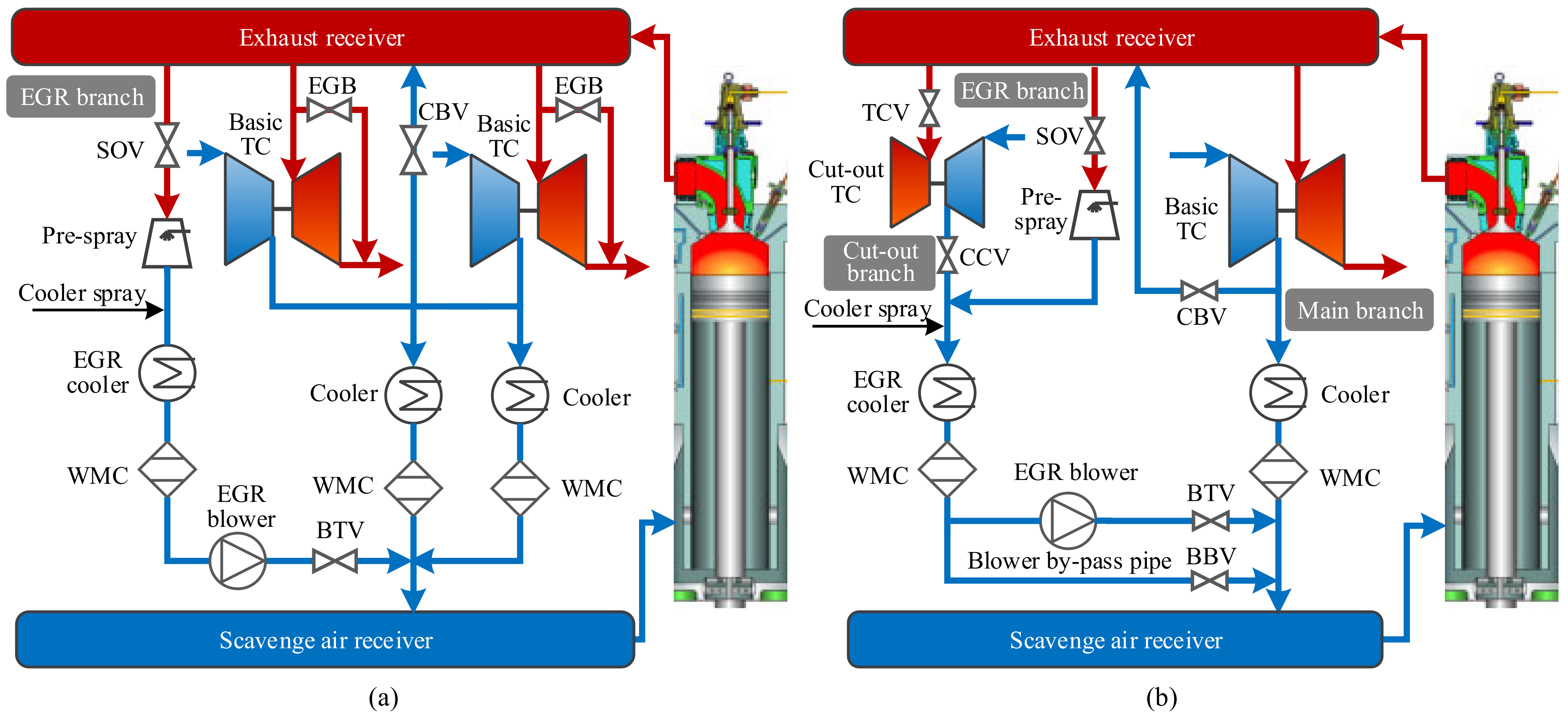
  • The baseline engine configuration (BL-EGR) consists of one or more turbochargers (TCs) of the same size connected in parallel. The EGR branch is connected between the exhaust gas and scavenging air receivers, while being switched on/off by a valve. The EGR flow is controlled by the EGR blower. A turbine bypass branch is switched on when the engine operates at high loads, with the EGR branch switched off to avoid the TC over speeding.
  • The alternative engine configuration (AL-EGR) consists of two turbochargers of different size (large and small) connected in parallel. The EGR branch is connected between the exhaust gas and scavenging air receivers, whereas it can be switched on/off by appropriate valves. With the EGR branch switched on, the small TC is switched off, whereas both TCs operate when the EGR branch is switched off.
The detailed descriptions of these two configurations are provided in Lu et al. [49], whereas their layouts are presented in Figure 1. The studies discussed in the preceding paragraphs [35,36,37,38,42,43,45,46,47], as well as more recent studies [50,51,52], focused on the BL- EGR configuration for marine diesel engines equipped with one TC unit. However, studies on the BL-EGR engine configuration for larger size marine diesel engines equipped with two or more parallel TCs are not available in the pertinent literature.
Studies on the AL-EGR engine configuration are limited. Kaltoft et al. [41] reported the shipboard testing and the corresponding results for a large marine two-stroke engine, whereas Kim and Kim [53] investigated the shafting system torsional vibrations and the carbon emissions. In a previous authors’ study [49], the capacity ratio between the large turbocharger (TC-L) and the small turbocharger (TC-S) was parametrically investigated, quantifying the effects of the TC selection on the engine performance parameters. However, comprehensive assessments of the BL-EGR and AL-EGR engine configurations, as well as studies to optimise the systems settings, are not available in the literature.
This study aims to parametrically optimise the EGR and turbocharging system settings for a large marine engine employed as the prime mover in an ocean-going tanker ship. Two engine configurations are modelled in the GT-SUITE v2020 software (Gamma Technologies: Westmont, IL, USA). Parametric runs were performed to quantify the impact of the EGR operation on the engine performance and emissions. A comparative assessment between the two investigated configurations is performed, which leads to recommendations for the operating modes and optimal settings for the most fuel-efficient engine operation complying with both NOx emissions Tier II and III limits.
Hence, this study, although it employs similar modelling tools as the previous authors’ study [49], investigates different scenarios and cases studies with different operating modes and parametric optimisation. This study’s novelty is associated with the following activities: (a) the parametric study of a large marine two-stroke diesel engine equipped with two parallel TCs of the same size (BL-EGR engine configuration); (b) the optimisation of the EGR and cylinder bypass rates for the BL-EGR engine configuration; (c) the quantification of the impact of the AL-EGR configuration settings on the performance and NOx emissions; (d) the recommendation of the most fuel-efficient operating modes for the AL-EGR engine configuration; and (e) a comparative assessment of the BL-EGR and AL-EGR engine configurations.

2. Methodology

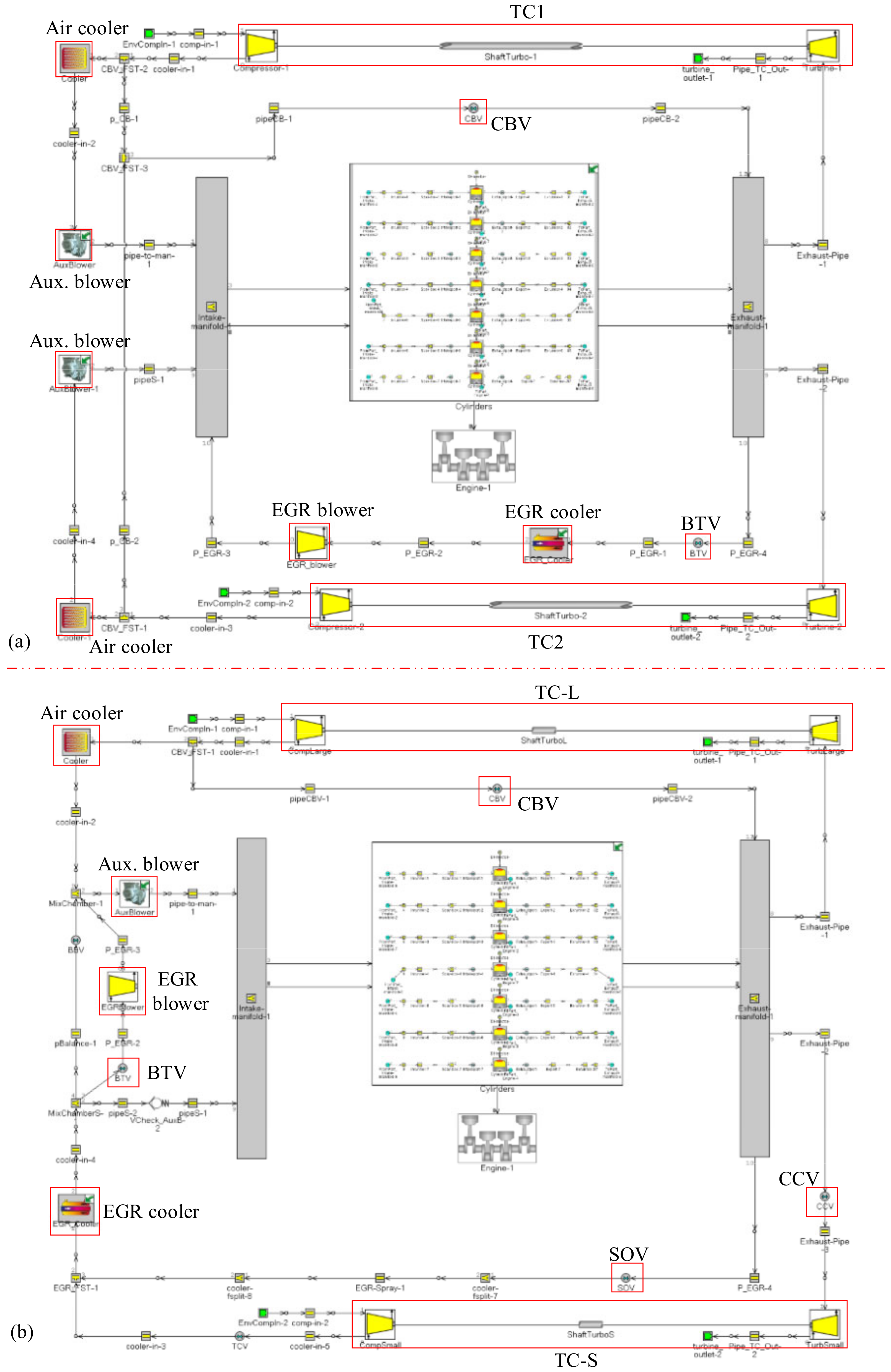
2.1. Engine Modelling Description

This study investigates the MAN 7G80ME engine, which is a large marine diesel engine of the two-stroke type. Table 1 lists the technical specifications of this engine according to [54]. The GT-SUITE software [55], which offers the tools and functionalities to enable effective engine modelling, was employed in this study to develop models of the zero/one-dimensional type that sufficiently represent both of the investigated engine configurations. These models were based on an existing model for the engine cylinders assembly (previously developed by the authors and reported in [49]). This model was subsequently expanded to incorporate the sub-models for the turbocharging and EGR systems. The flowcharts of the developed models are illustrated in Figure 2. The model of the BL-EGR engine configuration includes sub-models for the EGR system, the cylinder bypass branch, and the two identical TCs (TC1 and TC2). The model of the AL-EGR engine configuration includes sub-models for the EGR branch, the TC-L, the TC-S, and the cylinder bypass branch.

2.1.1. Engine Core Component Modelling

The DIPulse model [56,57,58], which is available in GT-SUITE, was used to represent the cylinders combustion. The NOx emissions were estimated by the use of the extended Zeldovich mechanism [59]. These models were calibrated by employing the engine performance data (indicated mean effective pressure (IMEP), cylinder pressure, charge air flow, and NOx emissions), at 25%, 50%, 75%, and 100% loads. Although the required data for modelling (the exhaust gas valve area, scavenging ports area, exhaust gas timing, air mass flow, injected fuel mass, start of injection, etc.) are available, the cylinder scavenging and the fuel injection parameters still need to be calibrated.
For calibrating the combustion model, the Three Pressure Analysis (TPA) model and the Measured and Predicted (M+P) Analysis model, available in GT-SUITE [60], were employed. TPA employs one cylinder block (including the scavenging ports, the exhaust valve, and the crank train) and uses the measured cylinder pressure as an input to calculate the cylinder heat release rate (HRR). The single-cylinder model was subsequently employed by providing the HRR as input and using the scavenging model to calculate the in-cylinder pressure variation. The calibration of the scavenging model was accomplished by comparing the simulated and measured cylinder pressures.
The M+P Analysis model is a single-cylinder engine model that includes the injector and the engine crank train. The air volumetric efficiency and the air trapping ratio of using the cylinder at 25%, 50%, 75%, and 100% engine loads were provided as inputs (instead of the scavenging model). This model employs the DI-Pulse combustion model to predict the in-cylinder pressure variation. The calibration of the injection model and the preliminary calibration of the combustion model were carried out by comparing the predicted and measured cylinder pressures.
The DIPulse model parameters that need calibration include the ignition delay, entrainment rate, premixed combustion rate, and diffusion combustion rate coefficients. A single set of values for these parameters is required to provide the best match at the whole-engine operating envelope. GT-SUITE includes the Advanced Direct Optimizer (ADO) [60] that was employed to optimise the DIPulse model parameters, selecting a Genetic Algorithm along with its default settings as presented in Table 2. The performed optimisation was targeted to minimise the objective function that includes the Root Mean Squared Error (RMSE) between the predicted and the measured burn rate; the latter was calculated by using the measured cylinder pressure, as explained in the previous paragraph. The recommended ranges of values for the DIPulse model multipliers are illustrated in Table 3 [60]. The optimisation function in the ADO was employed to carry out simulations in all considered operating points (25%, 50%, 75%, and 100% loads) at each iteration, the results of which were used to calculate the average RMSE.
The modelling details of the air cooler, the auxiliary, the scavenging receiver, exhaust receiver, and the connecting piping were previously described [49,61].
The weighted average values of the BSFC ( W B S F C ) [62] and the NOx emissions ( W N O x ), taking into account the 25%, 50%, 75%, and 100% loads, are used to compare the BSFC and the NOx emissions. W B S F C and W N O x are described according to the following equations:
W B S F C = ( B S F C i P i   W F i ) ( P i   W F i )
W N O x = ( N O x i P i   W F i ) ( P i   W F i )
where i is the engine load (25%, 50%, 75%, and 100%), B S F C , P ,   N O x , and W F are the BSFC, the engine power, and the NOx emissions the weighting factor, respectively [63].

2.1.2. Turbocharger and EGR System Modelling

The turbochargers are modelled by employing the respective performance maps of the compressors and turbines [49]. Considering that two TCs of the A270 type can provide the air flow rate required for the investigated engine operation at the MCR point, this TC unit was selected for the BL-EGR engine configuration. The compressor map of this TC [64,65] was provided as the input to the corresponding model. For the AL-EGR engine configuration, the compressor maps for the large and small TCs were estimated by scaling the compressor map of the A270 TC according to the air flow rate. The ratio between the TC-L and the TC-S capacities was considered to be 70:30, which is in alignment with the recommendations for the engine–turbocharging matching reported in Lu et al. [49]. It is noted that due to the lack of pertinent data, in all the scaled compressors maps, the pressure ratio, efficiency, and speed were assumed to be the same as that of the available map (although slight variations are expected). The turbine maps were estimated by scaling the swallowing capacity and efficiency curves of the respective available maps.
The engine coolers (air cooler and EGR cooler) are modelled by considering the cooler effectiveness as a function of the corresponding flow rates and the temperature of the cooling media at the inlet. The pressure drops are calculated as functions of the corresponding mass flow rates squared. The other engine piping (cylinder bypass (CB) and EGR branches) are modelled as one-dimensional elements by employing the equations derived by the mass, momentum, and energy conservation. The EGR blower controls the EGR rate, which is calculated as:
ϕ E G R = m ˙ E G R m ˙ E G R + m ˙ c m ˙ C B
where m ˙ E G R represents the EGR mass flow rate, m ˙ c represents the sum of the two TC compressor air mass flow rates, and m ˙ C B denotes the CB air mass flow rate.
The CB rate is calculated as:
ϕ C B = m ˙ C B m ˙ c

2.2. Optimisation of the EGR Rate for the AL-EGR Engine Configuration

It is essential to optimise the settings of the AL-EGR engine configuration operating at the TIII mode to minimise the engine BSFC and simultaneously reduce the engine NOx emissions below the respective limits. The optimisation was carried out considering the following four steps:
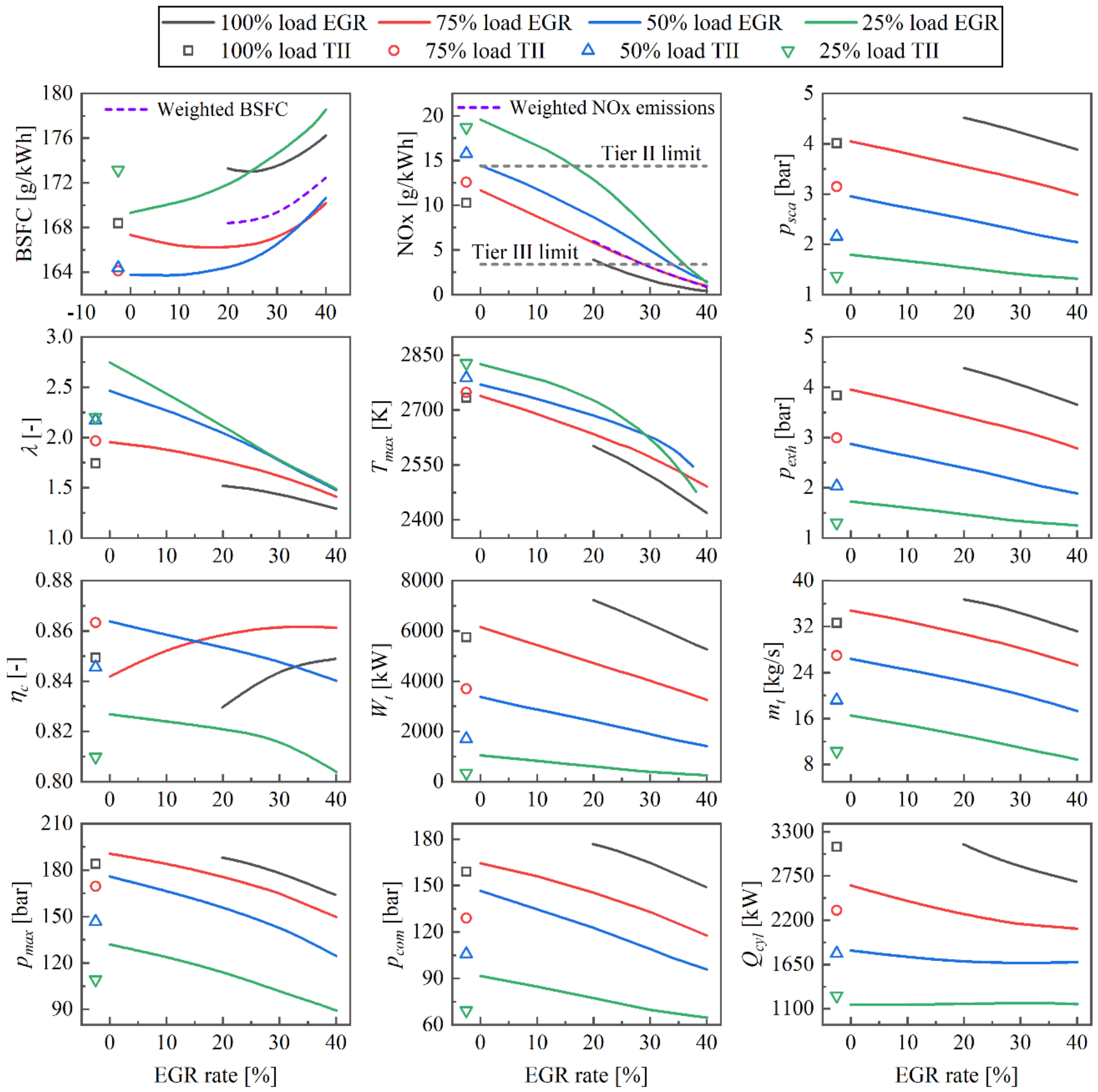
  • The AL-EGR engine configuration model was used to perform the simulation runs considering the engine operation with EGR rates up to 40% (TC-L and EGR are activated, whilst TC-S is deactivated). The derived BSFC and NOx emissions as a function of the EGR rate were obtained;
  • The derived simulation results were further processed by employing Gaussian fitting, considering the BSFC and NOx emissions as the dependent variables, whereas the EGR rate is taken as the independent variable;
  • The weighted BSFC and NOx functions as functions of the EGR rate (denoted with x) were estimated according to the following equations by employing the weighted BSFC and NOx for specific EGR rate values based on Equations (1) and (2).
F B S F C x = P i W F i f i x ( P i   W F i )
H N O x x = P i W F i h i x ( P i   W F i )
where i represents 25%, 50%, 75%, and 100% loads, whereas f i x , h i x , P i , and W F i represent the engine BSFC, the NOx emissions, the engine power, and the weighted factor at 25%, 50%, 75%, and 100% loads, respectively;
4.
The constrained, nonlinear, multivariable function that uses the interior-point algorithm in MATLAB R2020b (The MathWork Inc., Natick, MA, USA) was employed to optimise the EGR rates at 25%, 50%, 75%, and 100% engine loads, according to the following formulation:
  • Objective function: min F B S F C x ;
  • Optimised variables: X = x i , x i denotes the EGR rate (in percentage) at 25%, 50%, 75% and 100% loads;
  • Constraints: H N O x x ≤ 3.4 g/kWh, 20 < x i < 40. It should be noted that additional performance optimisation goals can be achieved by adjusting the constraint values of the upper and lower limits of the EGR rate at each load.

2.3. Simulated Cases

Simulation runs were carried out considering the engine operation with EGR rates up to 40%; however, the engine operation does not always comply with the TIII limits. Therefore, the term “EGR mode” was henceforth employed. The “TIII mode” constitutes a subset of the “EGR mode”, referring to the engine operating conditions with EGR that meet the TIII limits (which corresponds to 3.4 g/kWh).
For quantifying the effects of the EGR and TC system settings on the engine performance and NOx emissions, simulation runs were conducted for the engine operating at the TII mode (EGR branch switched off) and the EGR mode (0–40% EGR rates). For the BL-EGR engine configuration, to assess the impact of the CB rate on the TC performance improvement in the EGR mode, additional simulation runs were carried out considering the engine operation with the 40% EGR rate, as well as to optimise the CB and EGR rates for minimising the engine BSFC and ensuring compliance with the TIII limits. Furthermore, for the AL-EGR engine configuration, the simulation runs for the proposed operating modes were performed to assess their effectiveness for improving the engine BSFC, while still meeting the TIII limits. The overview of the performed simulation runs is presented in Table 4.

3. Results and Discussion

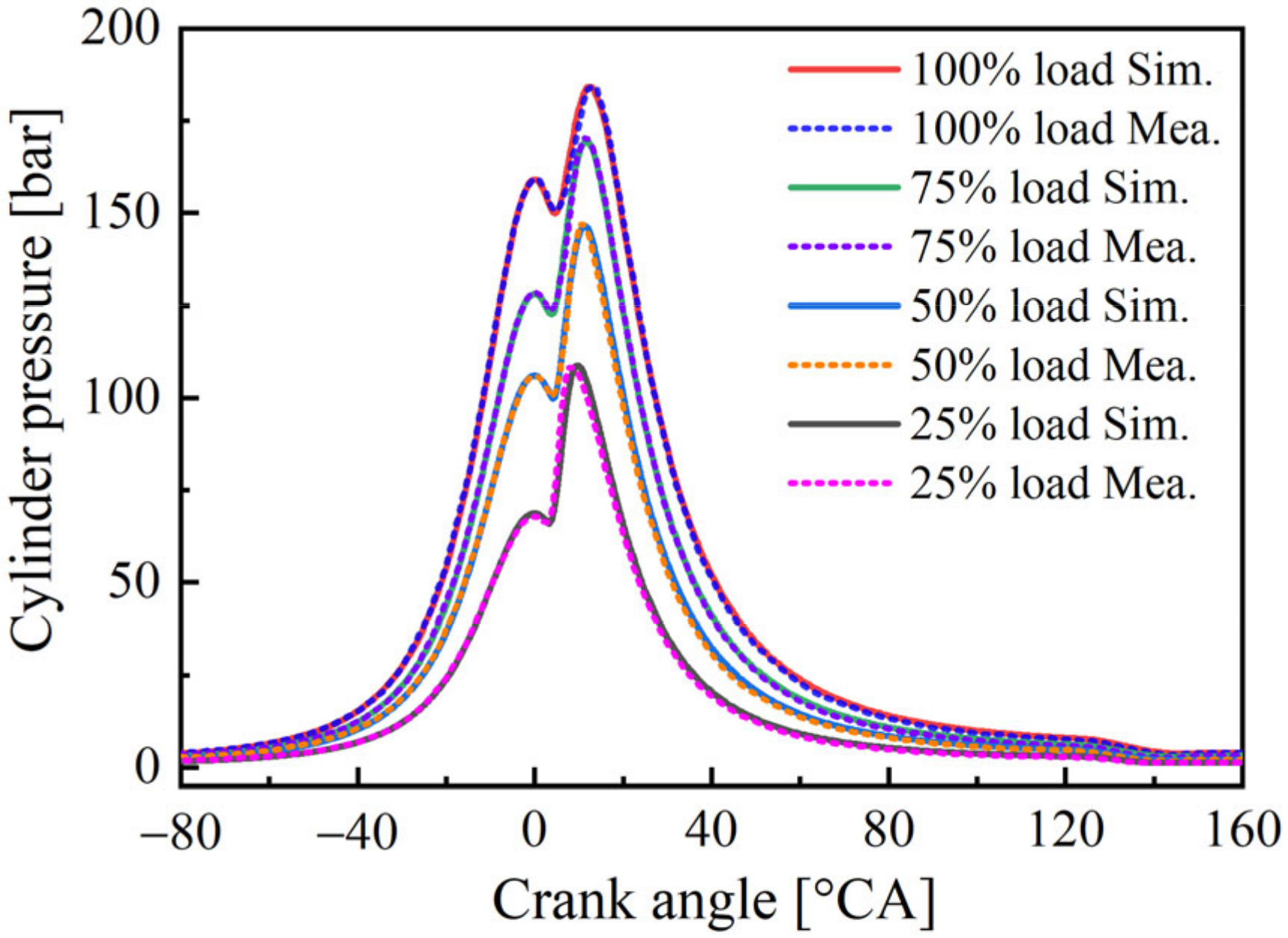
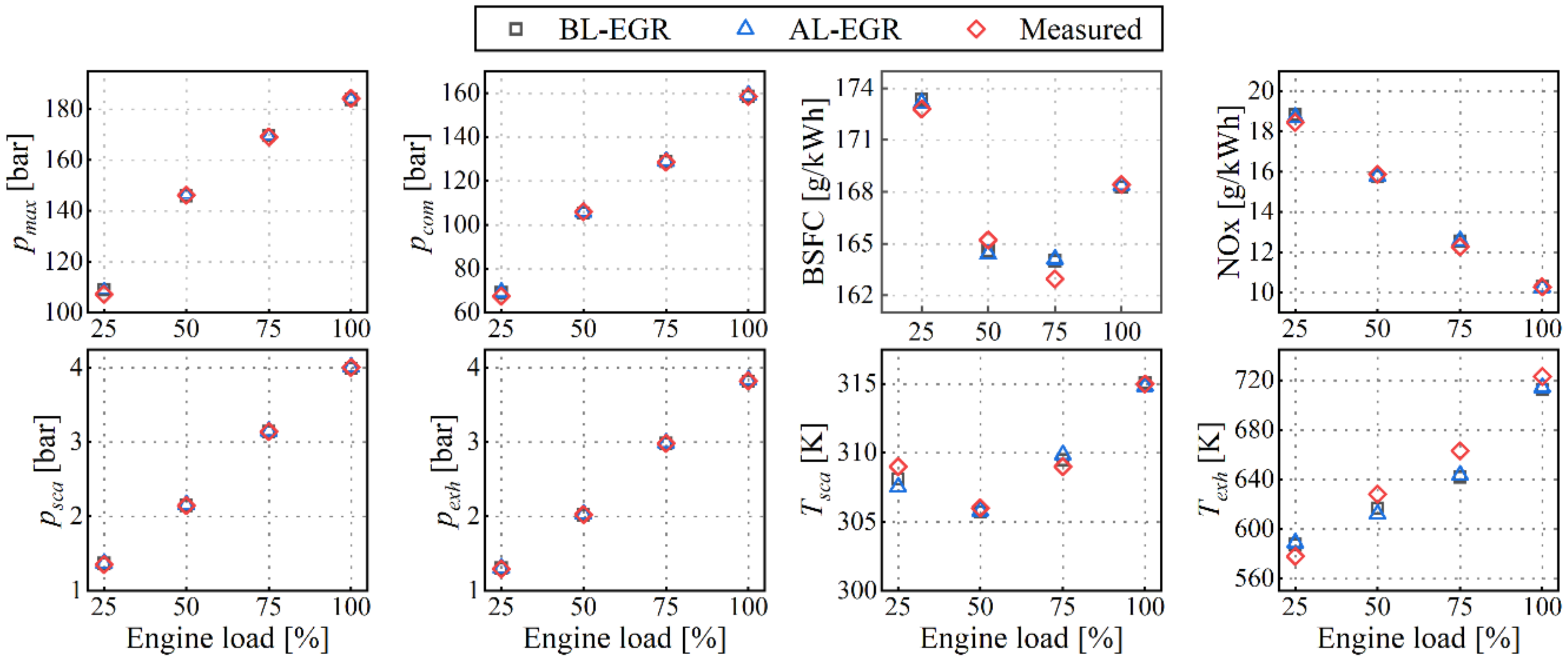
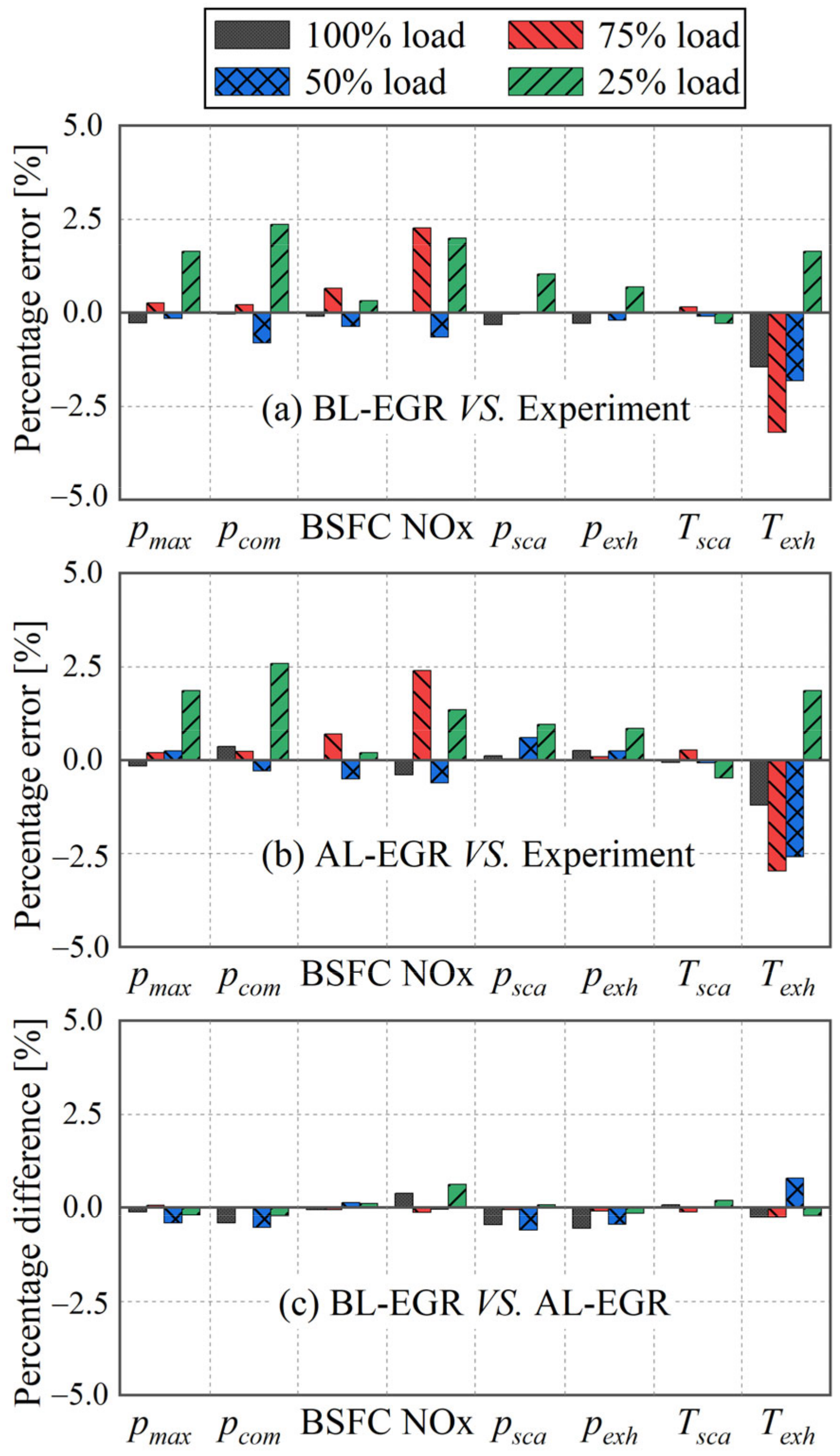
3.1. Model Validation

The model of the engine core assembly corresponding to the Tier II (TII) operating mode was validated against measured data during the engine shop trials corresponding to steady state conditions at several loads from 25% to 100%. To set up this model, the pressure and temperature at the engine core assembly boundaries, acquired at the engine factory acceptance tests, were employed as boundary conditions.
The obtained relative percentage errors between the predicted parameters and their respective measured values are summarised in Table 5. These errors are found within the range of ±3.2%. The measured and the predicted cylinder pressures are presented in Figure 3. The predicted values are in reasonable agreement with the measured values.
Simulation runs with the models of the BL-EGR and AL-EGR engine configurations at the TII mode (EGR system switched off) were conducted. Figure 4 presents the predicted results and their comparison with the respective measured values. As illustrated in Figure 5a,b, the relative percentage errors (between the measured and predicted values for the engine BL-EGR and AL-EGR configurations are found to be less than ±3.2%. The simulation predictions are in sufficient agreement with the measured values. Figure 5c presents the relative percentage difference between the predicted parameters from the models for the BL-EGR and AL-EGR engine configurations. As deviations less than ±0.8% were exhibited, it is deduced that the developed models can be used for the comparative assessment of the two engine configurations.

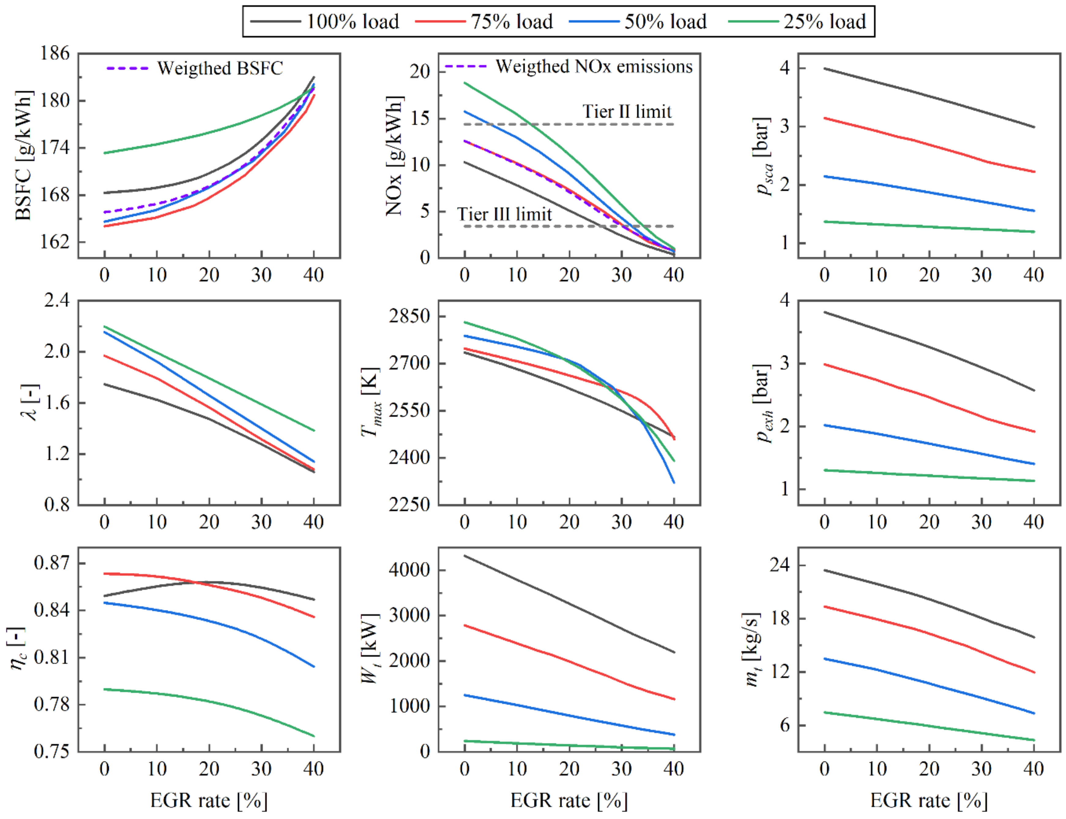
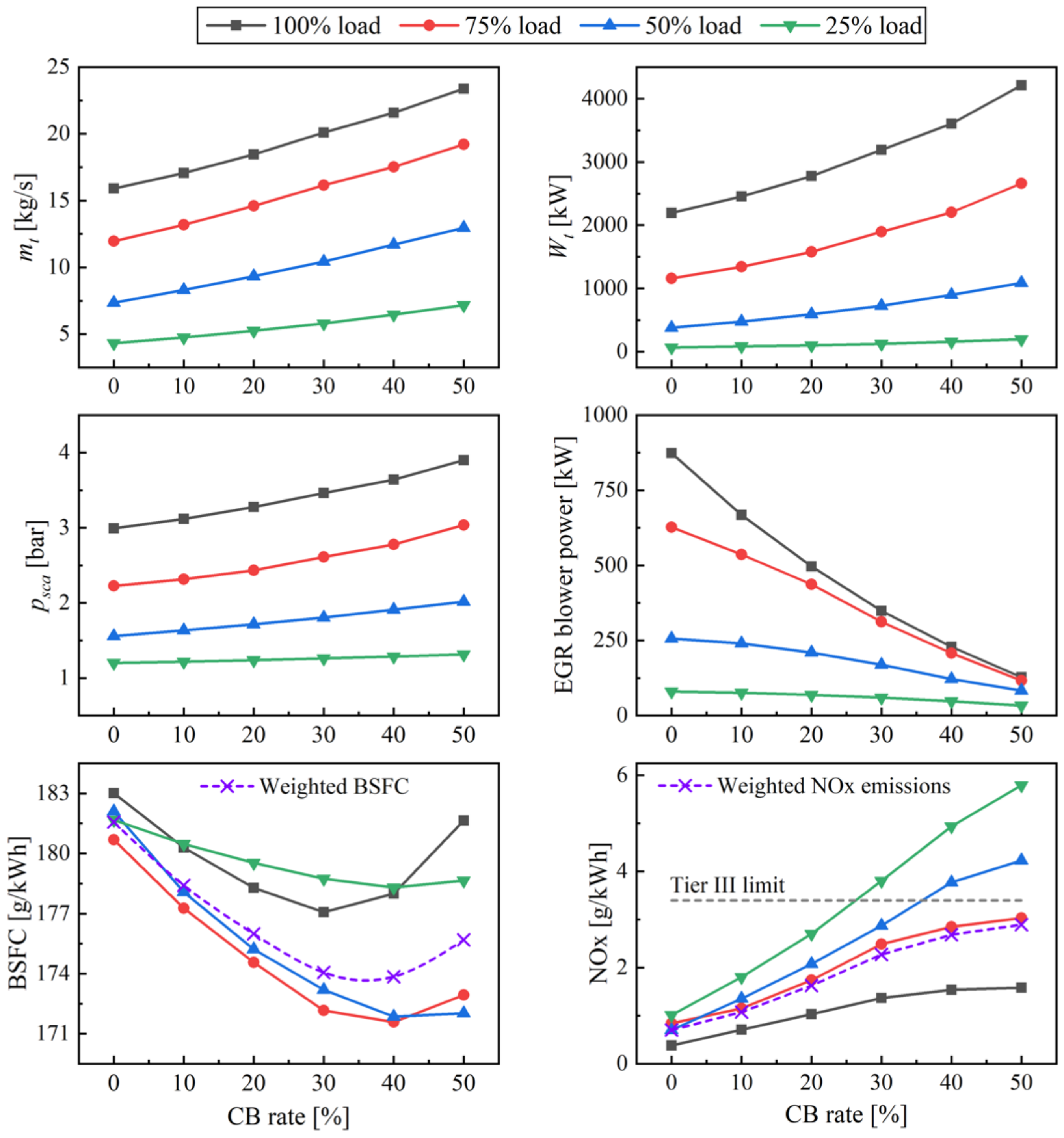
3.2. Impact of the BL-EGR Engine Configuration Settings on the Engine Performance and NOx Emissions

This section investigates the effects of the BL-EGR system settings on the engine performance and emissions. Simulations at steady state conditions were performed taking into account the engine running at the TII mode (EGR deactivated; EGR rate equals 0%), as well as the engine operation with EGR rates up to 40%. The predicted results are presented in Figure 6. It should be noted that the engine turbocharging system consists of two identical TC units connected in parallel, and, therefore, only the results for the first TC are presented.
The increase of the EGR rate results in decreased exhaust gas receiver pressure and the TC turbine flow, which, in turn, reduces the turbine power. Consequently, the compressor operates to areas of lower mass flow rate and pressure ratio, as shown in Figure 7, which causes the decrease of the scavenge air receiver pressure and the air–fuel ratio. As a result, the engine BSFC and NOx emissions are affected. As presented in Figure 6, the NOx emissions and the burned zone peak temperature at all investigated engine loads decrease with increasing EGR rate. According to the NOx generation mechanism, the reduction of the NOx emissions is mainly caused by the reduction of the burned zone peak temperature. For EGR rate values higher than 26%, the NOx emissions at 100% load reach values below 3.4 g/kWh (which corresponds to the TIII limits for this engine). For 25%, 50%, and 75% loads, meeting the TIII limits requires slightly higher EGR rates (34%, 32%, and 30.5%, respectively). The EGR rate corresponding to the weighted NOx emissions that comply with the TIII limits is about 30%, which results in a weighted BSFC of 173.6 g/kWh. Due to the slower combustion rate attributed to the decrease of the trapped air–fuel ratio, the engine BSFC at all investigated loads monotonously increase with increasing EGR rate. These results are in alignment with the pertinent literature [46] and provide the anticipated trade-off between the engine BSFC and the NOx emissions (decrease of the NOx emissions is associated with the BSFC increase).
It can be observed that the compressor surge margin decreases with an increase in the EGR rate. For the case of 40% EGR rate, the surge margin was calculated to be 10.8%, 16.3%, 25.1%, and 44.7% at 100%, 75%, 50%, and 25% loads, respectively. These values are within the acceptable limits (typically around 12%) accepted by the engine manufacturers for avoiding compressor surging during the engine transient operation. In addition, at 25%, 50%, and 75% engine loads, the compressor operates at lower efficiency areas. Figure 6 also demonstrates the change of the compressor efficiency with increasing EGR rate. At 25%, 50%, and 75% engine loads, the compressor efficiency fraction reduces by 0.02, 0.04, and 0.03, respectively, as the EGR rate increases from 0% to 40%. Moreover, at 25%, 50%, 75%, and 100% engine loads, the scavenge air receiver pressure decreases by 25%, 29%, 27%, and 13%, respectively, as the EGR rate increases from 0% to 40%.
A solution to compensate for the deterioration of the engine and turbocharger performance at higher EGR rates is to bypass the charge air bypass (from the compressor outlet to the turbine inlet) by switching on the cylinder bypass valve (CBV). The CB rate effects on the engine and turbochargers performance was investigated for an EGR rate of 40% (this value was selected as it resulted in the highest BSFC values).
As presented in Figure 8, the turbine power and exhaust gas mass flow increase with the increase of the CB rate at all investigated loads. Consequently, the adverse impacts for the EGR system operation on the compressor are attenuated. As shown in Figure 7, the compressor operating points for all investigated loads almost approach their position corresponding at the TII mode (0% EGR rate) whilst the CB rate increases to 50%. The scavenge air receiver pressure is also restored close to the respective levels at the TII mode. As a result, the engine BSFC is improved compared to the case of the closed CB valve, whereas the NOx emissions gradually increase. The minimum BSFC values are exhibited in the region of 30–40% CB rate, depending on the engine load. This is attributed to the compressor efficiency, which gradually approaches its peak value and then is reduced. It is deduced from Figure 7 that an optimal point of the CB rate exists for every load that minimises the BSFC, whilst the compliance of the weighted NOx emissions to the TIII limits is ensured. The CB rate optimal values (to achieve the lowest BSFC) are 40% for 25%, 50%, and 75% loads, whereas it is 30% for 100% load. Considering the weighted BSFC, the CB rate optimal value is about 35% and provides the minimum weighted BSFC of about 173.6 g/kWh.
In addition, the electrical power consumption of the EGR blower reduces with the CB valve opening, which is attributed to the lower pressure rise (from the exhaust gas receiver to the scavenge air receiver). When the CB system is deactivated, the EGR blower power is around 1.3%, 2.1%, 3.4%, and 3.6% of the engine brake power at 25%, 50%, 75%, and 100% loads, respectively, whereas it reduces to around 0.8%, 1.0%, 1.1%, and 1.4%, respectively, when optimal CB rates values are used.
The optimisation of the CB and EGR rates to minimise the engine BSFC of the BL-EGR engine operating in the TIII mode (complying with TIII limits; 3.4 g/kWh) was subsequently investigated by performing parametric runs, considering the ranges of the CB and EGR rates. The EGR rate was controlled in the model by adjusting the EGR blower speed (which affects the EGR blower power). Based on the derived simulation results, the EGR rates that minimise the BSFC for each engine load and CB rates in the range 0–50% are presented in Figure 9. At 25%, 50%, 75%, and 100% loads, the optimal CB rates were found to be 34%, 40%, 32%, and 9%, respectively, whereas the optimal EGR rates were calculated as 42.3%, 39.2%, 36.5%, and 27.1%, respectively. The engine BSFC values corresponding to these operating points were calculated as 178.9 g/kWh, 172.2 g/kWh, 170.8 g/kWh, and 172.9 g/kWh, respectively. Compared to the respective values with the CB valve closed, the engine BSFC reduced by 0.4 g/kWh, 1.4 g/kWh, 2.0 g/kWh, and 0.1 g/kWh.

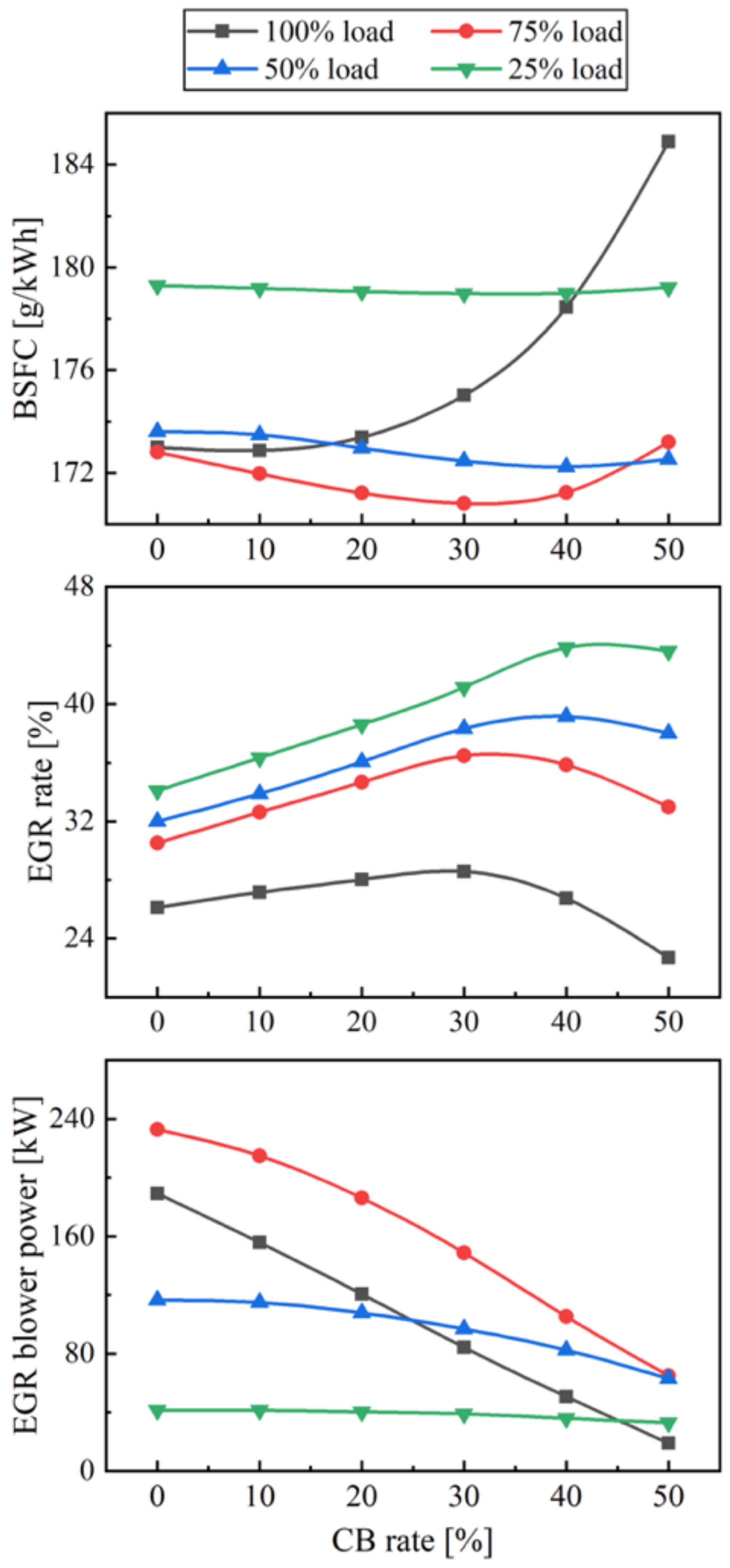
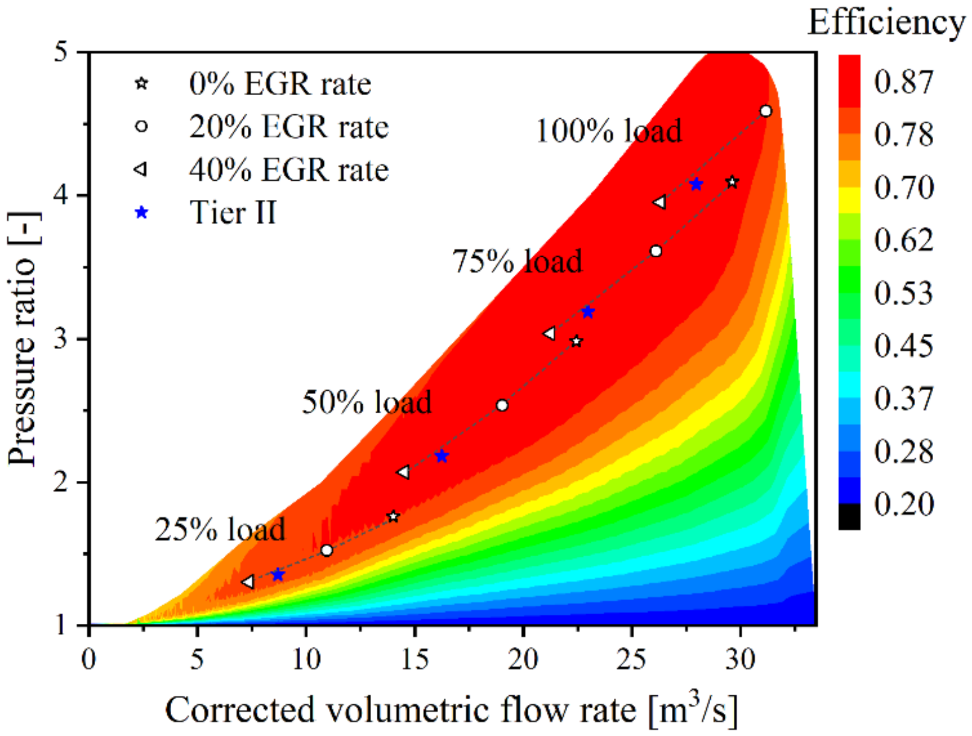
3.3. Impact of the AL-EGR Engine Configuration Settings on the Engine Performance and NOx Emissions

This section investigates the effects of the AL-EGR engine configuration settings on the engine performance and emissions parameters. Simulation runs at steady state conditions were carried out, taking into account the engine operation at the TII mode (TC-L and TC-S are switched on, whilst EGR is deactivated) as well as the EGR mode with EGR rates up to 40% (TC-L and EGR are activated, whilst TC-S is deactivated). The predicted results are illustrated in Figure 10; symbols denote the results for the TII mode, whereas the solid lines denote the results for the EGR mode). For the EGR mode and engine operating at 100% load, only the predicted results are illustrated for the EGR rates higher than 20%. For lower EGR rates, the TC-L speed exceeds the overspeed limit caused by the considerable increase of the exhaust gas pressure (leading to high exhaust gas mass flow rate). This demonstrates that a moderate EGR rate is unavoidable for the engine at 100% load. For operation at this load with EGR rates lower than 20%, alternative matching configurations are required, which include a larger TC-L size (and thus a smaller TC-S size) or exhaust gas bypass (EGB).
For the engine operation where the TC-S is deactivated, the equivalent exhaust gas flow area reduces, and the exhaust gas only flows through the TC-L turbine. Compared with the same loads in the TII mode, the exhaust gas receiver pressure increases, as only the TC-L operates. The increased exhaust gas pressure and mass flow rate lead to an increase of the turbine power, which causes the TC-L compressor to operate at a higher turbocharger speed, as shown in Figure 11. Consequently, the air mass flow rate and the scavenge air receiver pressure increase, which leads to an increase in the in-cylinder compression and maximum pressures. Figure 10 demonstrates that as the EGR rate increases, the TC-L compressor efficiency increases for 100% and 75% loads, whereas it decreases at 50% and 25% loads. Moreover, the TC-L compressor efficiency is lower than that in the TII mode at 75% and 100% loads (reduction is more pronounced at the higher load), whereas this situation is reversed at 25% and 50% loads (increase is more pronounced at the lower load). The air–fuel ratio is also affected by the cylinder scavenging efficiency; a decreasing trend in the air–fuel ratio is observed as the EGR rate increases. With the increase of the EGR rate, the TC-L turbine exhaust gas flow decreases, and the equivalent exhaust gas flow area gradually increases. Thus, the exhaust gas receiver pressure, the turbine power, the scavenge air receiver pressure, the cylinder compression pressure, the cylinder maximum pressure, and the air–fuel ratio gradually decrease. The operating points of the TC-L compressor move downwards and leftwards; however, the compressor surge margin is always maintained in an acceptable range (more than 16%).
As shown in Figure 10, the peak temperature of the cylinder burned zone and the NOx emissions at all investigated engine loads monotonously decrease with the EGR rate increase. At 100% load, the NOx emissions reduce below 3.4 g/kWh (denoting compliance with the TIII limits for EGR rates higher than 22%. For 25%, 50%, and 75% loads, compliance with the TIII limits requires a higher EGR rate (35.5%, 33.9%, and 28.8%, respectively). The minimum weighted BSFC is about 169.1 g/kWh with the 28.8% EGR rate taking into account that the weighted NOx emissions comply with the TIII limits.
In the EGR mode, the engine BSFC at different loads exhibits different variation trends with the increase of the EGR rate, as presented in Figure 10. At 25% and 50% loads, the engine BSFC increases monotonously with the increase of the EGR rate, which is attributed to the decrease of the in-cylinder maximum pressure caused by the decrease of scavenge air receiver pressure and the air–fuel ratio. In addition, the higher EGR rate causes a higher BSFC increase rate. It can be inferred that the air–fuel ratio has a greater impact on the combustion quality in the low air–fuel ratio zone, as it is also deduced from the simulation results shown in Figure 10. Excessively high EGR rates should be avoided, especially in the low engine loads. At 75% and 100% loads, with the EGR rate increase, the BSFC first decreases and then increases, although the air–fuel ratio monotonously decreases, which means that for the high loads, appropriately increasing the EGR rate can reduce NOx emissions without causing a significant engine BSFC increase. Moreover, the operating points of the TC-L compressor will move towards the high efficiency zone; for 100% load, the TC-L speed moves away from the overspeed limit with the increase of the EGR rate.
It must be noted that the engine operating in the EGR mode with the low EGR rates (0–20%) exhibits a lower BSFC than that in the TII mode at 25% and 50% loads, which is attributed to the apparent increase of the TC-L compressor efficiency and the scavenge air receiver pressure, as shown in Figure 10. It can be inferred that the increase of the compression pressure and the maximum pressure results in the reduction of the engine BSFC. It is apparent that the TC-L efficiency and the engine BSFC at 25% and 50% engine loads are improved for the engine running in the EGR mode with low EGR rates. Based on this finding, a fuel optimised TII mode was proposed, the details of which are described in Section 3.4. It is observed that at 75% load, the BSFC in the EGR mode with 0% EGR rate is greater than that in the TII mode, although the air–fuel ratio is only slightly lower, which is attributed to the engine–turbocharger matching setting in these two layouts.

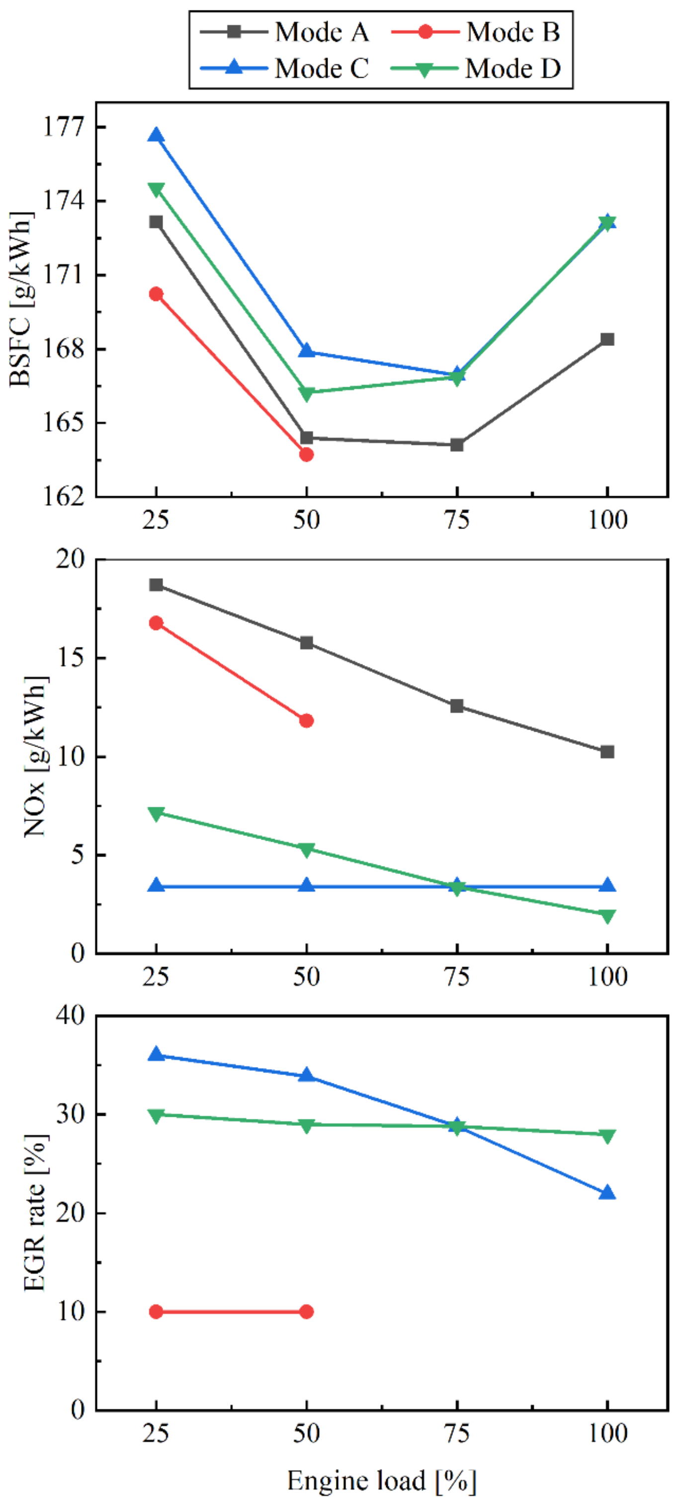
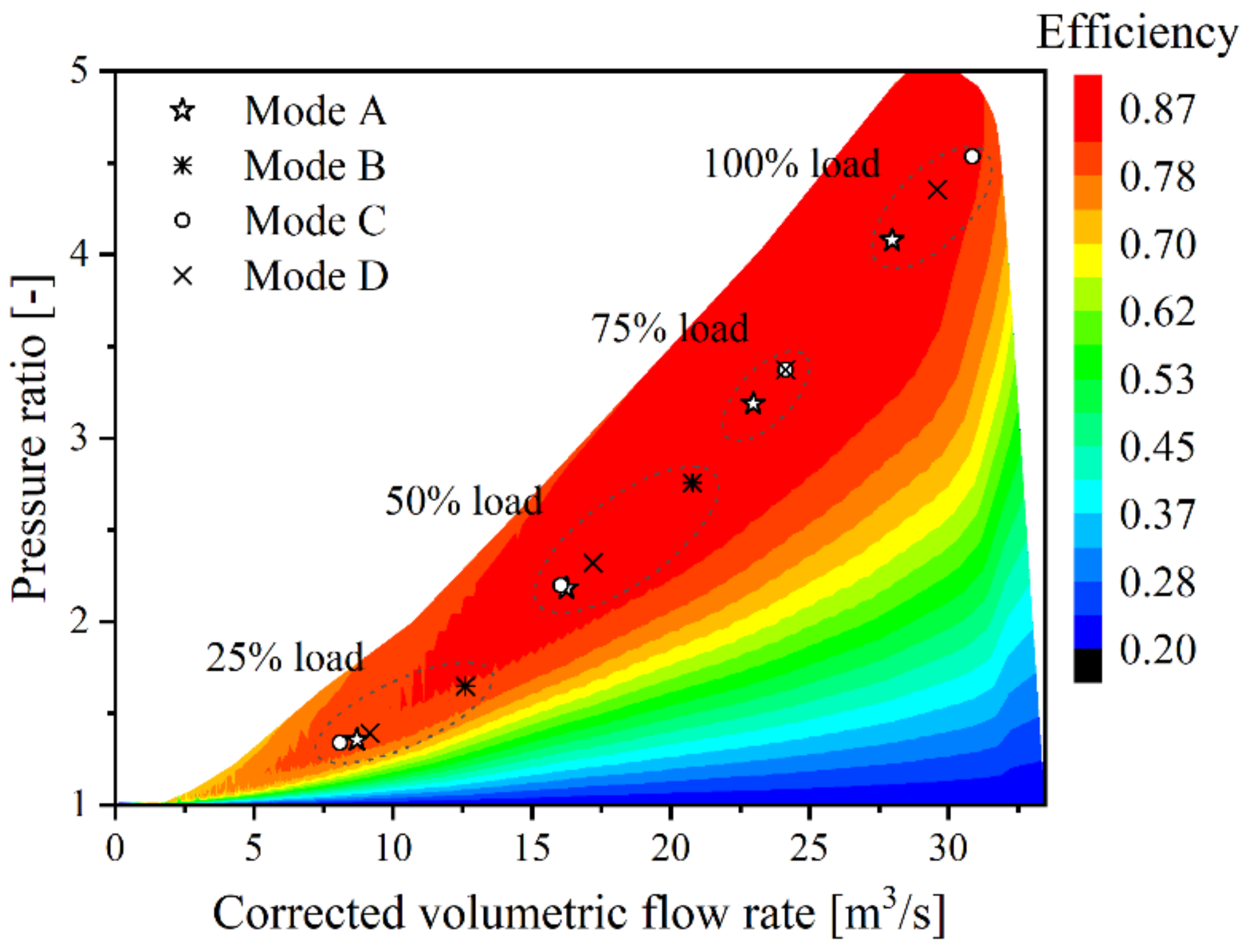
3.4. Proposed Operating Modes for the AL-EGR Engine Configuration

Based on the analysis in Section 3.3, the following four operating modes for the AL-EGR engine configuration are proposed: (1) Mode A (TII mode); (2) Mode B (fuel optimised TII mode); (3) Mode C (TIII mode); and (4) Mode D (optimised TIII mode).
Mode A is a general mode targeting the ship sailing in Non-ECAs. Operating in this mode with both TCs (TC-L and TC-S) activated and the EGR branch deactivated, the engine complies with the TII limits.
Mode B, a fuel-optimised TII mode, also complies with the TII limits and has a lower engine BSFC compared to mode A. It is only used at low loads (less than 50% load). In this mode, the TC-L is only activated (TC-S is deactivated) to increase the TC-L efficiency and the air–fuel ratio, which reduces the engine BSFC. It is recommended to cut off the EGR system to reduce the EGR system operating costs and maintenance workload. However, the EGR system can be activated at any time without restrictions in Mode B. It should be noted that the low EGR rate (10% EGR rate is investigated in this study) does not cause a significant increase of the engine BSFC, but it can further reduce the NOx emissions. Mode B is suitable for use in the following situations: (1) the TC-S encounters a fault or is under overhauling; (2) the engine has to operate at low loads, such as manoeuvring; (3) ship sails at reduced speed (slow steaming) to cut operating costs; or (4) transition stage of switching from Mode A to Mode C or D.
Mode C is the baseline TIII mode. In this mode, the TC-L is only activated (TC-S is deactivated) and the appropriate EGR rate is needed to ensure compliance with TIII limits (equal to 3.4 g/kWh) at all engine loads.
Mode D is a fuel-optimised TIII mode and is recommended for use within ECAs. The difference from Mode C is the application of the optimised EGR rates to ensure that the weighted NOx emissions comply with the TIII limits (equal to 3.4 g/kWh), whilst minimising the engine BSFC.
Figure 12 shows the predicted BSFC, NOx emissions, and required EGR rate at 25%, 50%, 75%, and 100% loads for the four proposed engine operating modes. Compared with Mode A, the engine BSFC and the NOx emissions in Mode B are both reduced, especially the engine BSFC at 25% load (lower by 2.9 g/kWh). In cases where the EGR system is deactivated, the engine BSFC further reduces. This is mainly attributed to the improvement of the TC-L efficiency and the movement of the operating points of the TC-L compressor to the high flow and pressure ratio zone (Figure 13), which leads to an increase in the engine air–fuel ratio (Figure 6). In addition, high compression pressure and temperature at low EGR rates are also beneficial to the combustion. The significant reduction of NOx emissions is attributed to the use of the EGR system. It should be noted that even if the EGR system is deactivated, the NOx emissions still comply with the TII emissions limits.
Compared with Mode C, the engine BSFC at 25% and 50% loads in Mode D reduces by 2.1 g/kWh and 1.66 g/kWh, respectively, whilst it only slightly changes at 75% and 100% loads. For 25% and 50% loads, the reduction of the EGR rate improves the TC-L compressor efficiency (Figure 10) and the operating point of the TC-L compressor moves to the high flow and pressure ratio zone (Figure 13), significantly increasing the air–fuel ratio (Figure 10), which, in turn, contributes to the improvement of the engine combustion performance. For 75% load, the engine BSFC remains almost constant, following a similar EGR rate pattern. For 100% load, although the increase of the EGR rate slightly reduces the air–fuel ratio, the lower average cylinder working medium temperature causes a reduction of the cylinder heat transfer loss (Figure 10). As a result, the engine BSFC only slightly increases. It is noted that the NOx emissions exhibit the opposite variation trend with the EGR rate increase at all investigated loads.
In summary, compared with Mode C, the weighted BSFC of 25%, 50%, 75%, and 100% loads for Mode D considerably reduces by 0.33 g/kWh, whilst the weighted NOx emissions remain unchanged (equals to 3.4 g/kWh). In addition, the EGR rates for all investigated loads are close to each other, and they are all maintained at around 30%, which will make the matching of the TC-L and the TC-S less challenging, since the capacity ratio of the TC-L and the TC-S can satisfy the engine air flow requirements for all loads. Moreover, operation according to the proposed mode D improves the TC-L efficiency and reduces the risk of TC-L overspeed at 100% load.

3.5. Comparative Assessment between the BL-EGR and AL-EGR Engine Configurations

Figure 14 presents the BSFC penalty and the EGR blower power consumption for the BL-EGR engine configuration operating in the TIII mode (NOx emissions just meets the TIII limit of 3.4 g/kWh) and the AL-EGR engine configuration operating in Mode D (optimised TIII mode). Except for 100% load, the BSFC penalty of the BL-EGR engine configuration is significantly greater than that of the AL-EGR engine configuration (around 4.2 g/kWh, 5.8 g/kWh, and 4.0 g/kWh at 25%, 50%, and 75% loads, respectively). Moreover, the BL-EGR engine configuration exhibits a higher EGR blower power compared with the AL-EGR engine configuration. The excess EGR blower powers are around 17 kW, 7 kW, 83 kW, and 117 kW at 25%, 50%, 75%, and 100% loads, respectively.
Figure 7 and Figure 11 show that the BL-EGR and the AL-EGR engine configurations have significantly different effects on the TC performance. For the BL-EGR engine configuration, the compressor operating points in the TII mode and the EGR mode with 0% EGR rate coincide. When the EGR branch is activated, the EGR reduces the mass flow of exhaust gas flowing through the turbine, resulting in the TC turbine power reduction. As the EGR rate increases from 0% to 40%, the compressor operating point of the BL-EGR engine configuration gradually moves from the position in the TII mode to the lower left (lower flow rate and pressure ratio), resulting in the reduction efficiency (and the compressor surge margin), and, as a result, the engine BSFC deteriorates. To reduce the EGR impact on compressor performance, the CB valve opening is employed as an effective measure.
For the AL-EGR engine configuration, the TC-L compressor operating point in the EGR mode with 0% EGR rate exhibits the largest deviation from its position in TII mode (moving upwards and rightwards). At high engine loads, the engine operation with 0% EGR rate will cause the TC-L overspeed, as well as excessive pressure and exhaust gas temperature, which may lead to engine and TC-L damage. Therefore, the mode switching between the TII mode and the EGR mode at high engine loads must be avoided. In the TIII mode, the exhaust gas flows through the TC-L turbine, as only the TC-L operates (TC-S is deactivated). This improves the TC-L performance and, thus, the TC-L compressor retains sufficient efficiency and acceptable surge margin. This effect was found to be more pronounced when the engine operates at low loads. As a result, the engine BSFC penalty for the AL-EGR engine configuration is lower compared to the BL-EGR engine configuration.
The corresponding requirements for the mode switching between the TII mode and the EGR mode for the BL-EGR and the AL-EGR engine configurations are different. For the BL-EGR engine configuration, the mode switching only needs to activate or deactivate the EGR branch and does not involve the activation or deactivation of any TC. Therefore, there is no strict requirement to switch operating modes. For the AL-EGR engine configuration, the mode switching involves the activation or deactivation of the EGR and the TC-S branches. Correspondingly, appropriate switching requirements and procedures are necessary. For example, the switching between the TII mode and the EGR mode should be performed at low loads (less than 50% load is recommended).
Although the introduction of the CB system increases the control complexity of the BL-EGR engine configuration, stricter requirements are expected for the mode switching and control of the AL-EGR engine configuration. As the EGR and the TC-S systems share some pipelines and components (EGR cooler and water mist catcher), the AL-EGR engine volume and cost are expected to be lower compared to the BL-EGR engine.

4. Conclusions

Two alternative configurations of a large marine two-stroke engine equipped with EGR systems (the baseline (BL-EGR) engine configuration and the alternative (AL-EGR) one) were numerically investigated, parametrically optimised, and comparatively assessed. Models for both engine configurations were developed in GT-SUITE and validated against pertinent engine measured data, indicating adequate accuracy. The major concluding remarks derived from this study are the following:
  • Both engine configurations complying with the Tier II NOx emissions limits exhibit almost similar performance and emissions, as their turbochargers operate at similar efficiency ranges;
  • For both configurations, EGR rates between 22% and 36% are required to render the engine meet the Tier III NOx emissions limits;
  • For the BL-EGR engine configuration, the engine BSFC increase can be compensated by opening the cylinder bypass valve, which also results in lower EGR blower power;
  • For the AL-EGR engine configuration, excessive EGR rates should be avoided at low engine loads, whereas the cylinder bypass opening is recommended to compensate for the engine BSFC increase;
  • For the AL-EGR engine configuration, a fuel-optimised Tier II mode (Mode B) is proposed for operation at low loads, demonstrating BSFC reduction up to 2.9 g/kWh compared to Mode A (standard Tier II mode). Furthermore, a fuel-optimised Tier III mode (Mode D) is proposed, improving the engine BSFC by up to 2.1 g/kWh compared to the non-optimised Tier III mode (Mode C);
  • The EGR rates of the proposed optimised modes were close to 30%, which makes the matching of the TC-L and the TC-S less challenging;
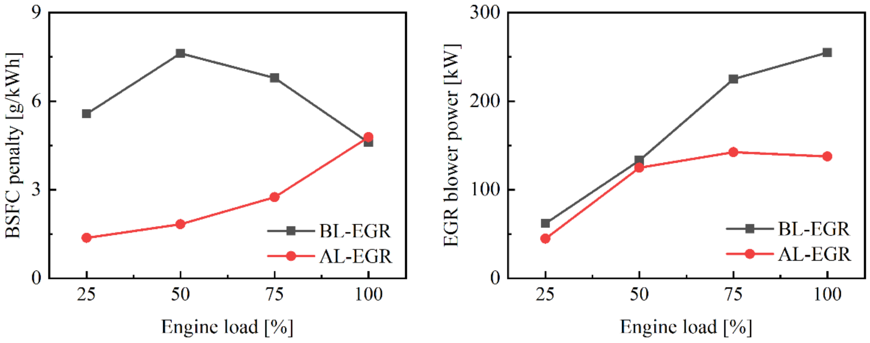
  • The AL-EGR engine configuration operating at the Tier III mode is more efficient (BSFC penalty was found reduced up to 5.8 g/kWh) and requires lower EGR blower power (up to 117 kW) compared to the BL-EGR engine configuration;
  • Compared to the BL-EGR engine, the AL-EGR engine is expected to occupy less volume, since part of the required pipelines and components (EGR cooler and water mist catcher) are shared between the EGR and turbocharging systems. However, the control logic of the AL-EGR engine is expected to be slightly more complex.
Taking into account the enormous pressure exerted on the shipping industry to reduce NOx emissions, the results of this investigation are useful for facilitating the decision-making process when selecting of the most fuel-efficient engine configuration, as well as for the optimisation of the engine operating modes. Future studies will investigate the effects of the TC activation/deactivation and controls on the operation of the engine configurations with the EGR systems, whilst considering the degradation of engine components.

Author Contributions

Conceptualization, D.L., G.T. and J.Z.; methodology, D.L., G.T. and J.Z.; software, D.L. and K.C.; validation, D.L. and K.C.; formal analysis, D.L. and G.T.; investigation, D.L.; resources, D.L. and K.C.; data curation, D.L. and H.Z.; writing—original draft preparation, D.L. and G.T.; writing—review and editing, D.L. and G.T.; visualization, D.L. and H.Z.; supervision, G.T. and J.Z.; project administration, D.L., G.T. and J.Z.; funding acquisition, J.Z. All authors have read and agreed to the published version of the manuscript.

Funding

This research was funded by the National Natural Science Foundation of China, grant number 62127806 and U1905212.

Institutional Review Board Statement

Not applicable.

Data Availability Statement

Data is contained within the article.

Acknowledgments

The authors affiliated with the Maritime Safety Research Centre (MSRC) greatly acknowledge the funding from DNV AS and RCCL for the MSRC establishment and operation. The opinions expressed herein are those of the authors and should not be construed to reflect the views of DNV AS or RCCL.

Conflicts of Interest

The authors declare no conflict of interest.

Nomenclature

m t Exhaust gas mass flow rate of turbine [kg/s]
p m a x Cylinder maximum pressure [bar]
p c o m Cylinder compression pressure [bar]
p e x h Exhaust gas receiver pressure [bar]
p s c a Scavenge air receiver pressure [bar]
P Engine power [kW]
Q c y l Cylinder heat transfer loss [kW]
T e x h Scavenge air receiver temperature [K]
T m a x Peak temperature of burned zone [K]
T s c a Scavenge air receiver temperature [K]
W F Weighting factor [-]
W B S F C Weighted average values of BSFC [g/kWh]
W N O x Weighted average values of NOx emissions [g/kWh]
W t Turbine power [kW]
λ Trapped air–fuel ratio [-]
η c Compressor efficiency [-]

Abbreviations

AL-EGR   Alternative engine configuration
BL-EGRBaseline engine configuration
BSFCBrake-specific fuel consumption
BTVBlower throttle valve
CBCylinder bypass
CBVCylinder bypass valve
CCVCompressor cut-out valve
ECAsEmission Control Areas
EGBExhaust gas bypass valve
EGRExhaust gas recirculation
HP-EGRHigh-pressure EGR
LP-EGRLow-pressure EGR
MCRMaximum continuous rating
SOVEGR shut-off valve
TCTurbocharger
TC-LLarge turbocharger
TC-SSmall turbocharger
TCVTurbine cut-out valve
TIITier II
TIIITier III

References

  1. United Nations. COVID-19 and Maritime Transport: Impact and Responses. In Transport and Trade Facilitation Series No. 15; United Nations Conference on Trade and Development; United Nations: San Francisco, CA, USA, 2021. [Google Scholar]
  2. Murphy, A.J.; Norman, A.J.; Pazouki, K.; Trodden, D.G. Thermodynamic simulation for the investigation of marine Diesel engines. Ocean Eng. 2015, 102, 117–128. [Google Scholar] [CrossRef] [Green Version]
  3. Lloyd’s Register. Emissions of Nitrogen Oxides from Marine Diesel Engines; Lloyd’s Register: London, UK, 2002. [Google Scholar]
  4. International Maritime Organization. Annex VI of MARPOL 73/78, Regulations for the Prevention of Air Pollution from Ships and NOx Technical Code; International Maritime Organization: London, UK, 2008. [Google Scholar]
  5. International Maritime Organization. Report of the Marine Environment Protection Committee on Its Seventy-First Session; Annex 1 Resolution MEPC.286(71), (Designation of the Baltic Sea and the North Sea Emission Control Areas); International Maritime Organization: London, UK, 2017. [Google Scholar]
  6. Paul, A.; Bose, P.K.; Panua, R.S.; Banerjee, R. An experimental investigation of performance-emission trade off of a CI engine fueled by diesel-compressed natural gas (CNG) combination and diesel-ethanol blends with CNG enrichment. Energy 2013, 55, 787–802. [Google Scholar] [CrossRef]
  7. Ammar, N.R.; Seddiek, I.S. Eco-environmental analysis of ship emission control methods: Case study RO-RO cargo vessel. Ocean Eng. 2017, 137, 166–173. [Google Scholar] [CrossRef]
  8. Agarwal, A.K.; Srivastava, D.K.; Dhar, A.; Maurya, R.K.; Shukla, P.C.; Singh, A.P. Effect of fuel injection timing and pressure on combustion, emissions and performance characteristics of a single cylinder diesel engine. Fuel 2013, 111, 374–383. [Google Scholar] [CrossRef]
  9. Ozkan, M.; Ozkan, D.B.; Ozener, O.; Yilmaz, H. Experimental study on energy and exergy analyses of a diesel engine performed with multiple injection strategies: Effect of pre-injection timing. Appl. Therm. Eng. 2013, 53, 21–30. [Google Scholar] [CrossRef]
  10. Liu, J.; Yang, F.; Wang, H.; Ouyang, M.; Hao, S. Effects of pilot fuel quantity on the emissions characteristics of a CNG/diesel dual fuel engine with optimized pilot injection timing. Appl. Energy 2013, 110, 201–206. [Google Scholar] [CrossRef]
  11. Andreadis, P.; Zompanakis, A.; Chryssakis, C.; Kaiktsis, L. Effects of the fuel injection parameters on the performance and emissions formation in a large-bore marine diesel engine. Int. J. Engine Res. 2011, 12, 14–29. [Google Scholar] [CrossRef]
  12. How, H.G.; Masjuki, H.H.; Kalam, M.A.; Teoh, Y.H. Influence of injection timing and split injection strategies on performance, emissions, and combustion characteristics of diesel engine fueled with biodiesel blended fuels. Fuel 2018, 213, 106–114. [Google Scholar] [CrossRef]
  13. Pelic, V.; Mrakovcic, T.; Radonja, R.; Valcic, M. Analysis of the Impact of Split Injection on Fuel Consumption and NOx Emissions of Marine Medium-Speed Diesel Engine. J. Mar. Sci. Eng. 2020, 8, 820. [Google Scholar] [CrossRef]
  14. Rakopoulos, C.D.; Rakopoulos, D.C.; Mavropoulos, G.C.; Kosmadakis, G.M. Investigating the EGR rate and temperature impact on diesel engine combustion and emissions under various injection timings and loads by comprehensive two-zone modeling. Energy 2018, 157, 990–1014. [Google Scholar] [CrossRef]
  15. Sun, X.; Liang, X.; Shu, G.; Lin, J.; Wang, Y.; Wang, Y. Numerical investigation of two-stroke marine diesel engine emissions using exhaust gas recirculation at different injection time. Ocean Eng. 2017, 114, 90–97. [Google Scholar] [CrossRef]
  16. Aalam, C.S.; Saravanan, C.G.; Anand, B.P. Impact of high fuel injection pressure on the characteristics of CRDI diesel engine powered by mahua methyl ester blend. Appl. Therm. Eng. 2016, 106, 702–711. [Google Scholar] [CrossRef]
  17. Li, T.; Gao, Y.; Wang, J.; Chen, Z. The Miller cycle effects on improvement of fuel economy in a highly boosted, high compression ratio, direct-injection gasoline engine: EIVC vs. LIVC. Energy Convers. Manag. 2014, 79, 59–65. [Google Scholar] [CrossRef]
  18. Zhao, J. Research and application of over-expansion cycle (Atkinson and Miller) engines—A review. Appl. Energy 2017, 185, 300–319. [Google Scholar] [CrossRef]
  19. Golovitchev, V.I.; Mattarelli, E.; Rinaldini, C.A. Potential of the Miller cycle on a HSDI diesel automotive engine. Appl. Energy 2013, 112, 102–119. [Google Scholar] [CrossRef]
  20. Gonca, G.; Sahin, B.; Parlak, A.; Ust, Y.; Ayhan, V.; Cesur, I.; Boru, B. Theoretical and experimental investigation of the Miller cycle diesel engine in terms of performance and emission parameters. Appl. Energy 2015, 138, 11–20. [Google Scholar] [CrossRef]
  21. Park, H.K.; Ghal, S.H.; Park, H.C.; Choi, S.W.; Kim, S.H. A Study on NOx Reduction of Marine 4-Stroke Diesel Engine Using Charge Air Humidification; SAE International: Warrendale, AR, USA, 2011. [Google Scholar]
  22. Zhang, Z.G.; Zhao, C.P.; Wang, Y.H.; Sun, Y.K.; Zheng, Z.Q. Effects of Intake Air Humidification on Combustion and Emissions in a Marine Diesel Engine. Combust. Sci. Technol. 2017, 23, 436–442. [Google Scholar] [CrossRef]
  23. Fahd, M.E.A.; Yang, W.; Lee, P.S.; Chou, S.K.; Yap, C.R. Experimental investigation of the performance and emission characteristics of direct injection diesel engine by water emulsion diesel under varying engine load condition. Appl. Energy 2013, 102, 1042–1049. [Google Scholar] [CrossRef]
  24. Zhu, S.; Hu, B.; Akehurst, S.; Copeland, C.; Branney, A. A review of water injection applied on the internal combustion engine. Energy Convers. Manag. 2019, 184, 139–158. [Google Scholar] [CrossRef]
  25. Alahmer, A.; Yamin, J.; Sakhrieh, A.; Hamdan, M.A. Engine performance using emulsified diesel fuel. Energy Convers. Manag. 2010, 51, 1708–1713. [Google Scholar] [CrossRef]
  26. Ghojel, J.; Honnery, D.; Al-Khaleefi, K. Performance, emissions and heat release characteristics of direct injection diesel engine operating on diesel oil emulsion. Appl. Therm. Eng. 2006, 26, 2132–2141. [Google Scholar] [CrossRef]
  27. Ithnin, A.M.; Noge, H.; Abdul Kadir, H.; Jazair, W. An overview of utilizing water-indiesel emulsion fuel in diesel engine and its potential research study. J. Energy Inst. 2014, 87, 273–288. [Google Scholar] [CrossRef]
  28. Zhou, S.; Gao, R.; Feng, Y.; Zhu, Y. Evaluation of Miller cycle and fuel injection direction strategies for low NOx emission in marine two-stroke engine. Int. J. Hydrog. Energy 2017, 42, 20351–20360. [Google Scholar] [CrossRef]
  29. Imperato, M.; Kaario, O.; Sarjovaara, T.; Larmi, M. Split fuel injection and Miller cycle in a large-bore engine. Appl. Energy 2016, 162, 289–297. [Google Scholar] [CrossRef]
  30. Bozza, F.; De Bellis, V.; Teodosio, L. Potentials of cooled EGR and water injection for knock resistance and fuel consumption improvements of gasoline engines. Appl. Energy 2016, 169, 112–125. [Google Scholar] [CrossRef]
  31. Jain, A.; Singh, A.P.; Agarwal, A.K. Effect of split fuel injection and EGR on NOx and PM emission reduction in a low temperature combustion (LTC) mode diesel engine. Energy 2017, 122, 249–264. [Google Scholar] [CrossRef]
  32. Sarangi, A.K.; Garner, C.P.; McTaggart-Cowan, G.P.; Davy, M.H.; Wahab, E.; Peckham, M. The effects of split injections on high exhaust gas recirculation low-temperature diesel engine combustion. Int. J. Engine Res. 2013, 14, 68–79. [Google Scholar] [CrossRef]
  33. NOx Reduction by Exhaust Gas Recirculation—MAN Explains. Available online: https://www.egcsa.com/exhaust-gas-recirculation-explained/ (accessed on 5 October 2021).
  34. Zheng, M.; Reader, G.T.; Hawley, J.G. Diesel engine exhaust gas recirculation—A review on advanced and novel concepts. Energy Convers. Manag. 2004, 45, 883–900. [Google Scholar] [CrossRef]
  35. MAN Diesel & Turbo. Exhaust Gas Emission Control Today and Tomorrow: Application on MAN B&W Two-Stroke Marine Diesel Engines; MAN Diesel & Turbo: Copenhagen, Denmark, 2008. [Google Scholar]
  36. Ji, W.X.; Li, A.; Lu, X.C.; Huang, Z.; Zhu, L. Numerical study on NOx and ISFC co-optimization for a low-speed two-stroke engine via Miller cycle, EGR, intake air humidification, and injection strategy implementation. Appl. Therm. Eng. 2019, 153, 398–408. [Google Scholar] [CrossRef]
  37. Imperato, M.; Kaario, O.; Larmi, M.; Sarjovaara, T. Emission reduction methods and split fuel injection in a marine four-stroke engine. J. Mar. Sci. Eng. 2018, 23, 94–103. [Google Scholar] [CrossRef]
  38. Shirai, T.; Skjoldager, P.; Yokobe, S.; Ibaragi, S. EGR system development on MES test engine 4S50ME-T9. In Proceedings of the 27th CIMAC World Congress, Shanghai, China, 13–17 May 2013. [Google Scholar]
  39. Hiraoka, N.; Miyanagi, A.; Kuroda, K.; Ito, K.; Nakagawa, T.; Ueda, T. The World’s First Onboard Verification Test of UE Engine with Low Pressure EGR complied with IMO’s NOx Tier III Regulations. Mitsubishi Heavy Ind. Tech. Rev. 2016, 53, 40. [Google Scholar]
  40. Nakagawa, T.; Ito, K.; Edo, K.; Miyanagi, A. The Latest Technologies of NOx Emission Control for UE Engines. In Proceedings of the 29th CIMAC World Congress, Vancouver, BC, Canada, 10–14 June 2019. [Google Scholar]
  41. Kaltoft, J.; Preem, M. Development of integrated EGR system for two-stroke diesel engines. In Proceedings of the 27th CIMAC World Congress, Shanghai, China, 13–17 May 2013. [Google Scholar]
  42. Higashida, M.; Nakamura, T.; Onishi, I.; Nakao, S.; Hosono, T.; Nishiyama, A. Challenge of environmentally-friendly low emission system to Tier 3 for two-stroke diesel engines. In Proceedings of the 28th CIMAC World Congress, Helsinki, Finland, 6–10 June 2016. [Google Scholar]
  43. Moser, M.; Busk, K.; Lockner, E.; Glas, G. Emissions Reduction through Sophisticated Control Strategies. In Proceedings of the 29th CIMAC World Congress, Vancouver, BC, Canada, 10–14 June 2019. [Google Scholar]
  44. Lion, S.; Vlaskos, I.; Taccani, R. A review of emissions reduction technologies for low and medium speed marine Diesel engines and their potential for waste heat recovery. Energy Convers. Manag. 2020, 207, 112553. [Google Scholar] [CrossRef]
  45. Wang, Z.G.; Zhou, S.; Feng, Y.M.; Zhu, Y.Q. EGR modeling and fuzzy evaluation of Low-Speed Two-Stroke marine diesel engines. Sci. Total Environ. 2020, 706, 135444. [Google Scholar] [CrossRef]
  46. Duan, X.; Liu, Y.; Liu, J.; Lai, M.C.; Jansons, M.; Guo, G.; Zhang, S.; Tang, Q. Experimental and numerical investigation of the effects of low-pressure, high-pressure and internal EGR configurations on the performance, combustion and emission characteristics in a hydrogen-enriched heavy-duty lean-burn natural gas SI engine. Energy Convers. Manag. 2019, 195, 1319–1333. [Google Scholar] [CrossRef]
  47. Wang, D.; Shi, L.; Zhu, S.; Liu, B.; Qian, Y.; Deng, K. Numerical and thermodynamic study on effects of high and low pressure exhaust gas recirculation on turbocharged marine low-speed engine. Appl. Energy 2020, 261, 114346. [Google Scholar] [CrossRef]
  48. MAN Energy Solutions. MAN Emission Project Guide: MAN B&W Two-Stroke Marine Engines; MAN Energy Solutions: Copenhagen, Denmark, 2019. [Google Scholar]
  49. Lu, D.; Theotokatos, G.; Zhang, J.; Zeng, H.; Cui, K. Parametric investigation of a large marine two-stroke diesel engine equipped with exhaust gas recirculation and turbocharger cut out systems. Appl. Therm. Eng. 2022, 200, 117654. [Google Scholar] [CrossRef]
  50. Tang, X.Y.; Wang, P.; Zhang, Z.Y.; Zhang, F.L.; Shi, L.; Deng, K.Y. Effects of high-pressure and donor-cylinder exhaust gas recirculation on fuel economy and emissions of marine diesel engines. Fuel 2022, 309, 122226. [Google Scholar] [CrossRef]
  51. Stoumpos, S.; Theotokatos, G. Multiobjective Optimisation of a Marine Dual Fuel Engine Equipped with Exhaust Gas Recirculation and Air Bypass Systems. Energies 2020, 13, 5021. [Google Scholar] [CrossRef]
  52. Alegret, G.; Llamas, X.; Vejlgaard-Laursen, M.; Eriksson, L. Modeling of a large marine two-stroke diesel engine with cylinder bypass valve and EGR system. IFAC-Pap. Elsevier Sci. 2015, 48, 273–278. [Google Scholar] [CrossRef]
  53. Kim, Y.G.; Kim, U.K. Effects of torsional vibration of a propulsion shafting system and energy efficiency design index from a system combining exhaust gas recirculation and turbocharger cut out. J. Mech. Sci. Technol. 2019, 33, 3629–3639. [Google Scholar] [CrossRef]
  54. MAN Energy Solutions. MAN B&W G80ME-C9.5-TII Project Guide Electronically Controlled Two-Stroke Engines, 1st ed.; Publication No. 7020-0157-04ppr; MAN Energy Solutions: Copenhagen, Denmark, 2018. [Google Scholar]
  55. Gamma Technologies. GT-SUITE Manual; Gamma Technologies: Westmont, IL, USA, 2016. [Google Scholar]
  56. Piano, A.; Millo, F.; Boccardo, G.; Rafigh, M.; Gallone, A.; Rimondi, M. Assessment of the Predictive Capabilities of a Combustion Model for a Modern Common Rail Automotive Diesel Engine; SAE World Congress and Exhibition: Detroit, MI, USA, 2016. [Google Scholar]
  57. Jung, J.; Song, S.; Hur, K.B. Numerical study on the effects of intake valve timing on performance of a natural gas-diesel dual-fuel engine and multi-objective Pareto optimization. Appl. Therm. Eng. 2017, 121, 604–616. [Google Scholar] [CrossRef]
  58. Park, S.; Cho, J.; Park, J.; Song, S. Numerical study of the performance and NOx emission of a diesel-methanol dual-fuel engine using multi-objective Pareto optimization. Energy 2017, 124, 272–283. [Google Scholar] [CrossRef]
  59. Lavoie, G.A.; Heywood, J.B.; Keck, J.C. Experimental and Theoretical Study of Nitric Oxide Formation in Internal Combustion Engines. Combust. Sci. Technol. 1970, 1, 313–326. [Google Scholar] [CrossRef]
  60. Gamma Technologies. Engine Performance Application Manual; Gamma Technologies: Westmont, IL, USA, 2016. [Google Scholar]
  61. Gamma Technologies. Flow Theory Manual; Gamma Technologies: Westmont, IL, USA, 2016. [Google Scholar]
  62. Sun, K.; Zhu, S.; Lu, Z.; Deng, K. Research on Turbocharging Systems Matching with Marine Low-Speed Two-Stroke Diesel Engines Using EGR. Diesel Engine 2018, 40, 1–7. [Google Scholar]
  63. China Classification Society. Testing and Inspection Guide on Nitrogen Oxide Emissions of Marine Diesel Engines; China Classification Society: Beijing, China, 2020. [Google Scholar]
  64. Shen, H.; Zhang, C.; Zhang, J.; Yang, B.; Jia, B. Applicable and comparative research of compressor mass flow rate and isentropic efficiency empirical models to marine large-scale compressor. Energies 2020, 13, 47. [Google Scholar] [CrossRef] [Green Version]
  65. Shen, H.; Zhang, J.; Yang, B.; Jia, B. Development of a Marine Two-Stroke Diesel Engine MVEM with In-Cylinder Pressure Trace Predictive Capability and a Novel Compressor Model. J. Mar. Sci. Eng. 2020, 8, 204. [Google Scholar] [CrossRef] [Green Version]
Figure 1. Baseline engine configuration (a) and alternative engine configuration (b) (CBV, cylinder bypass valve; EGB, exhaust gas bypass valve; WMC, water mist catcher; BTV, blower throttle valve; SOV, EGR shut-off valve; TCV, turbine cut-out valve; CCV, compressor cut-out valve).
Jmse 10 00351 g001
Figure 2. Flowcharts of GT-SUITE models for: (a) the baseline (BL-EGR) engine configuration; and (b) the alternative (AL-EGR) engine configuration.
Jmse 10 00351 g002
Figure 3. Predicted and measured cylinder pressure of the engine in the Tier II mode.
Jmse 10 00351 g003
Figure 4. Comparison of predicted values against measured data for the BL-EGR and AL-EGR engine configurations at the Tier II mode.
Jmse 10 00351 g004
Figure 5. Relative percentage errors of the engine at the Tier II mode: (a) between predicted and measured values for the BL-EGR engine configuration; (b) between predicted and measured values for the AL-EGR engine configuration; and (c) predicted values for the BL-EGR and AL-EGR engine configurations.
Jmse 10 00351 g005
Figure 6. Effects of BL-EGR engine configuration setting on performance and NOx emissions (λ, trapped air–fuel ratio; T m a x , peak temperature of burned zone; η c , compressor efficiency; W t , turbine power; m t , exhaust gas mass flow rate of turbine).
Jmse 10 00351 g006
Figure 7. Impact of the EGR rate and the CB rate on the compressor operating points of the BL-EGR engine configuration.
Jmse 10 00351 g007
Figure 8. CB rate impact on engine performance and power consumption of an EGR blower for the BL-EGR engine configuration with 40% EGR rate.
Jmse 10 00351 g008
Figure 9. Optimisation study results for the BL-EGR engine configuration operating at the Tier III mode.
Jmse 10 00351 g009
Figure 10. Effects of AL-EGR on engine performance and NOx emissions ( Q c y l , cylinder heat transfer loss).
Jmse 10 00351 g010
Figure 11. Effects of EGR rate on TC-L compressor operating points of the AL-EGR engine configuration.
Jmse 10 00351 g011
Figure 12. Predicted BSFC, NOx emissions, and required EGR rate for the four studied engine operating modes.
Jmse 10 00351 g012
Figure 13. TC-L compressor operating points for the four studied engine operating modes.
Jmse 10 00351 g013
Figure 14. Engine BSFC penalty and EGR blower power of the BL-EGR and the AL-EGR engine configurations operating at the Tier III mode.
Jmse 10 00351 g014
Table 1. Engine specifications.
TermsValue
Cylinder bore [m]0.8
Cylinder number [–]7
Stroke to bore ratio [–]4.65
Engine Speed at MCR 1 [rpm]58
Brake Engine Power at MCR [MW]24.44
Brake Mean effective pressure at MCR [bar]19.3
NOx reduction technologyEGR
TC-LABB A275
TC-SABB A265
1 MCR, Maximum continuous rating.
Table 2. Recommended settings of the Genetic Algorithm in the Advanced Direct Optimizer (ADO).
ParametersValue
Population size30
Number of generations34
Mutation rate0.5
Mutation rate distribution index15
Table 3. Recommended ranges of the DIPulse model coefficients.
CoefficientsMinimumMaximum
Ignition delay0.952.8
Entrainment rate0.31.7
Premixed combustion rate0.052.5
Diffusion combustion rate0.41.4
Table 4. Overview of the performed simulation runs.
ModelEngine Load (%)EGR Rate (%)Scope
Model of the engine block assembly;
Model of the BL-EGR engine configuration;
Model of the AL-EGR engine configuration
25; 50; 75; 100Not usedValidation against measured data
Model of the BL-EGR engine configuration25; 50; 75; 1000−40Quantification of the variations of the engine performance and NOx emissions as function of the EGR rate
Assessment of the impact of the BL-EGR system on the compressor performance
Identification of the EGR rate to meet TIII limits
40assess the effects of the CB rate for improving the TC performance and the electrical power consumption of the EGR blower
20−50Optimisation of the CB and EGR rates to minimise the engine BSFC ensuring compliance with the TIII limits
Model of the AL-EGR engine configuration25; 50; 75; 1000−40Quantification of the variations of the engine performance and NOx emissions as function of the EGR rate
Assessment of the impact of the AL-EGR system on compressor performance
Model of the AL-EGR engine configuration25; 50; 75; 10010−40Recommendation of the most fuel-efficient operating modes for the AL-EGR engine configuration complying with TII and TIII limits
Table 5. Relative percentage errors between predicted and measured values of the engine in the Tier II mode.
ParametersLoad [%]
255075100
Cylinder maximum pressure p m a x −0.2−0.20.31.3
Cylinder compression pressure p c o m 0.2−0.5−0.11.8
Brake specific fuel consumption−0.10.7−0.50.3
Brake NOx emissions−0.32.8−0.71.0
Scavenge air receiver pressure 1 p s c a −0.1−0.60.80.2
Exhaust gas receiver pressure 1 p e x h −0.1−0.70.50.1
Scavenge air receiver temperature 2 T s c a 0.00.3−0.1−0.6
Exhaust gas receiver temperature 2 T e x h −1.5−3.2−2.32.1
1 The absolute pressure was employed for calculating the pressure relative error. 2 K was used for calculating the temperature relative error.
Publisher’s Note: MDPI stays neutral with regard to jurisdictional claims in published maps and institutional affiliations.

