
Collision Risk Index Calculation Based on an Improved Ship Domain Model

Abstract
:1. Introduction
1.1. The Static Ship Domain Model
1.2. The Dynamic Analytical Ship Domain Model
1.3. The Fuzzy Ship Domain Model

| Domain By | Ship-Related Factor | Environment-Related Factors | Shape |
|---|---|---|---|
| Fuji [1] | Own ship’s size and target ship’s size | Weather conditions | Ellipse |
| Goodwin [3] | N/A | Weather conditions and COLREGs | Circular |
| Davis [4] | Own ship’s size | COLREGs | Circular |
| Coldwell [5] | Own ship’s size | Encounter situations and COLREGs | Ellipse |
| Sun [6] | N/A | Encounter situations, weather conditions, traffic conditions, and COLREGs | Ellipse |
| Pietrzykowski [8] | Own ship’s size, speed, and maneuverability | Weather conditions and traffic conditions | Polygon |
| Hanse [10] | Own ship’s size | N/A | Ellipse |
| Jia [11] | Own ship’s size and speed | Encounter situations and weather conditions | Ellipse |
| Wang Y.Y [15] | Own ship’s size and speed, and target ship’s size and speed | COLREGs | Polygon |
| Pietrzykowski [22] | Own ship’s size, speed, and maneuverability | Encounter situations, weather conditions, and traffic conditions | Ellipse |
| Wang Ning [23,24] | Own ship’s size, speed, and maneuverability | Encounter situations, weather conditions, COLREGs, and human factors | QSD |
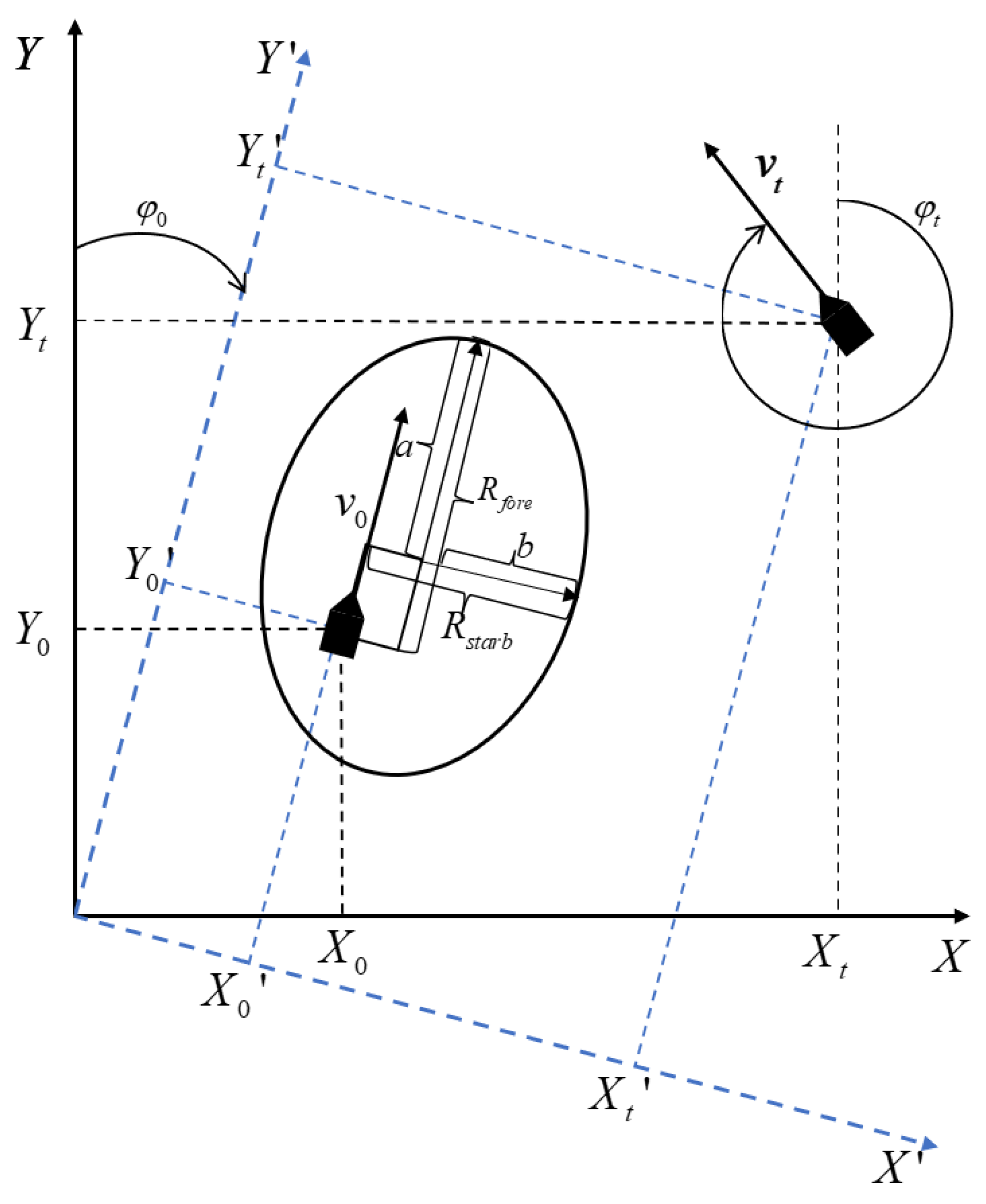
2. Construction of Elliptical Dynamic Ship Domain Model
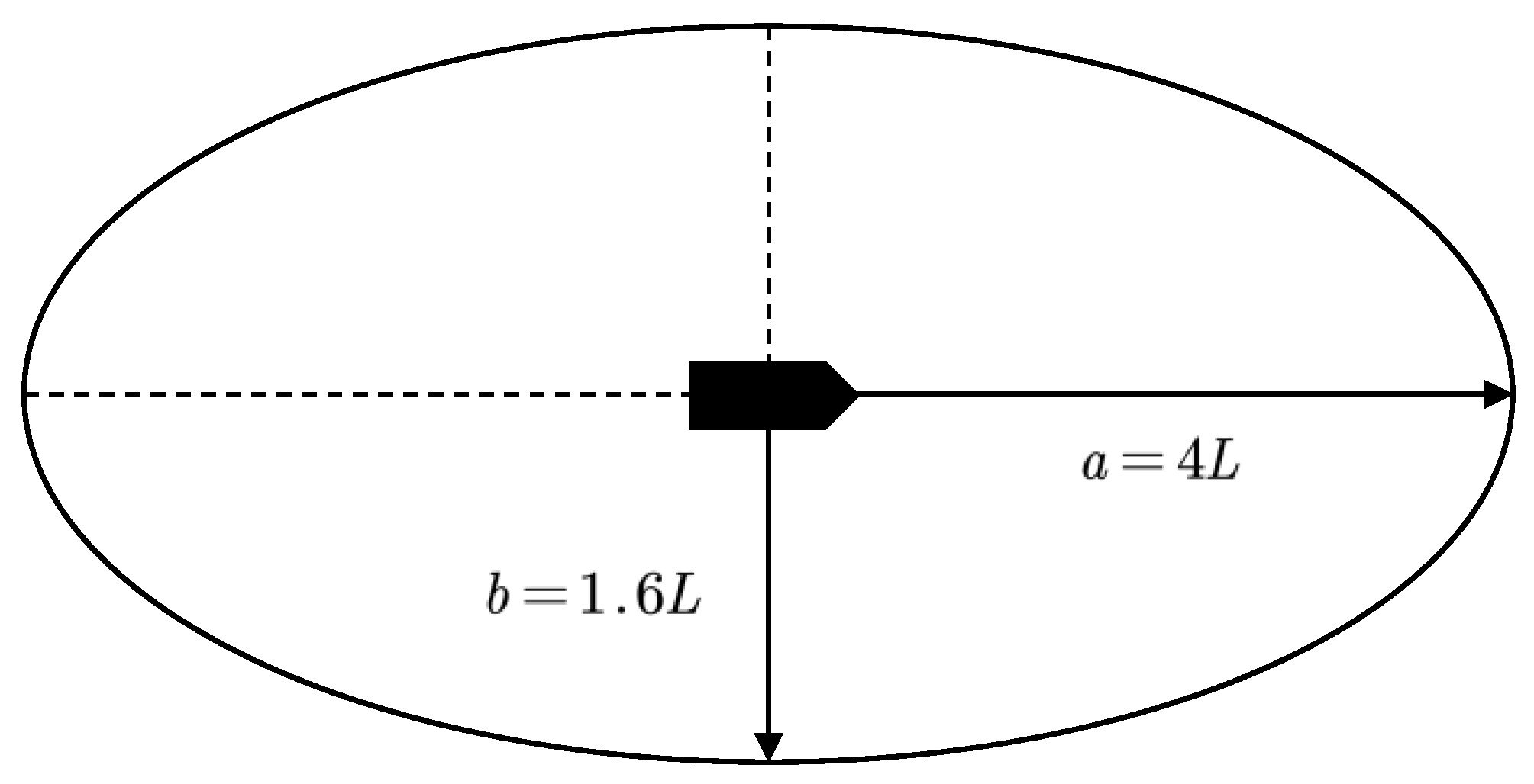
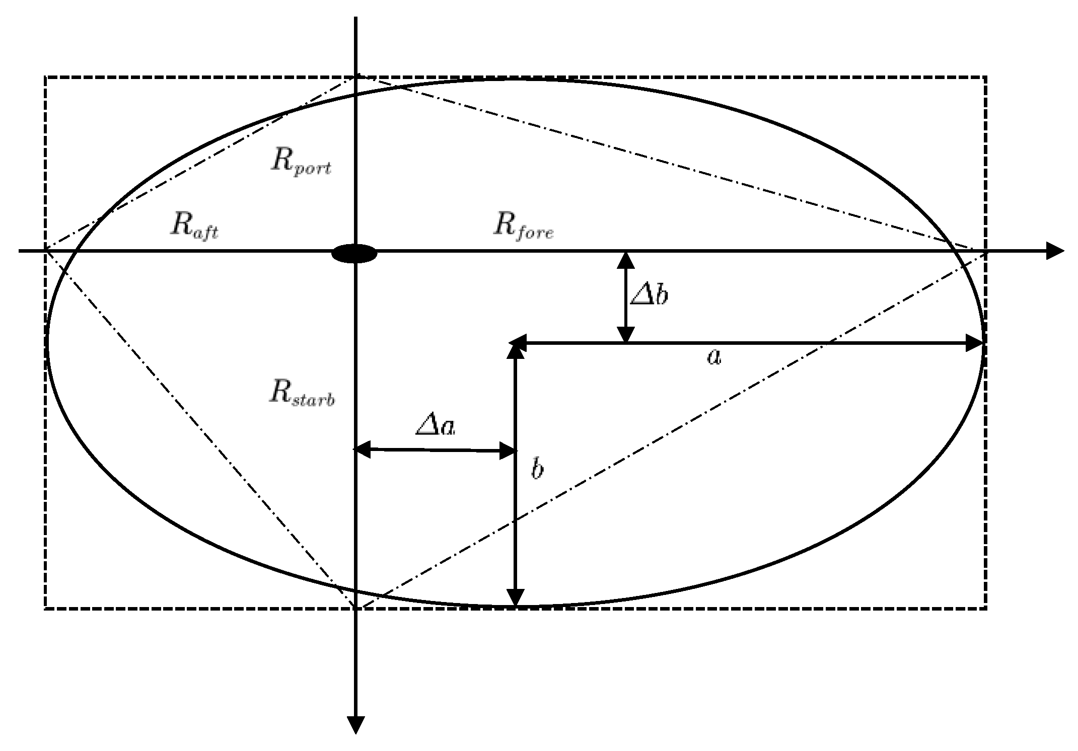
2.1. Elliptical Ship Domain Model
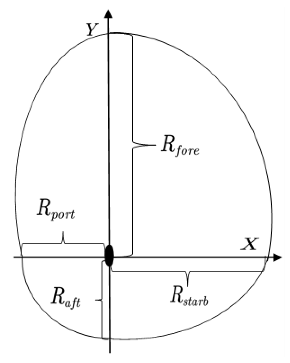
2.2. Quaternion Ship Domain Model
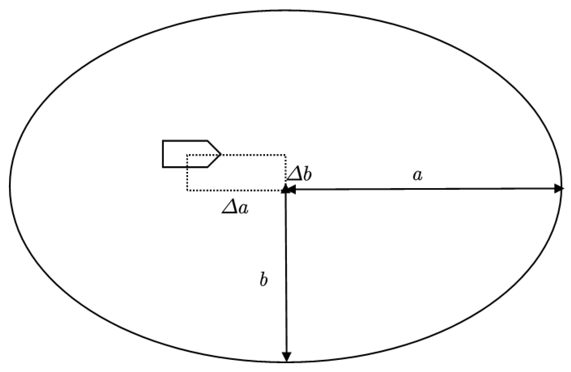
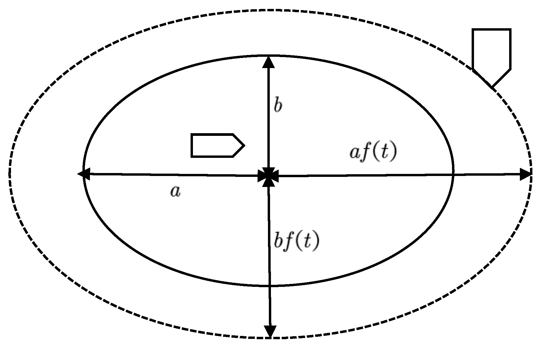
2.3. Construction of Elliptic Dynamic Ship Domain Model
2.3.1. Construction Principles
- (1)
- For the convenience of calculation and application, the elliptic ship domain is retained.
- (2)
- Considering the COLREGs and ship maneuvering habits, the ship cannot be set at the center of the ship domain, but will be offset like in the Coldwell ship domain. This study intends to offset the ship from the center of the elliptical ship domain to its lower left.
- (3)
- The size of the ship’s domain is related to the speed and maneuvering parameters of the ship, and it should be a dynamic domain that varies with the speed and length of the ship.
2.3.2. Constructive Method
2.3.3. Ship Domain Model Calculation
3. Collision Risk Index Model Based on Improved Ship Domain
3.1. Collision Risk Index
3.2. CRI Model Based on Improved Ship Domain
3.2.1. Calculation of CRI Based on Ship Domain
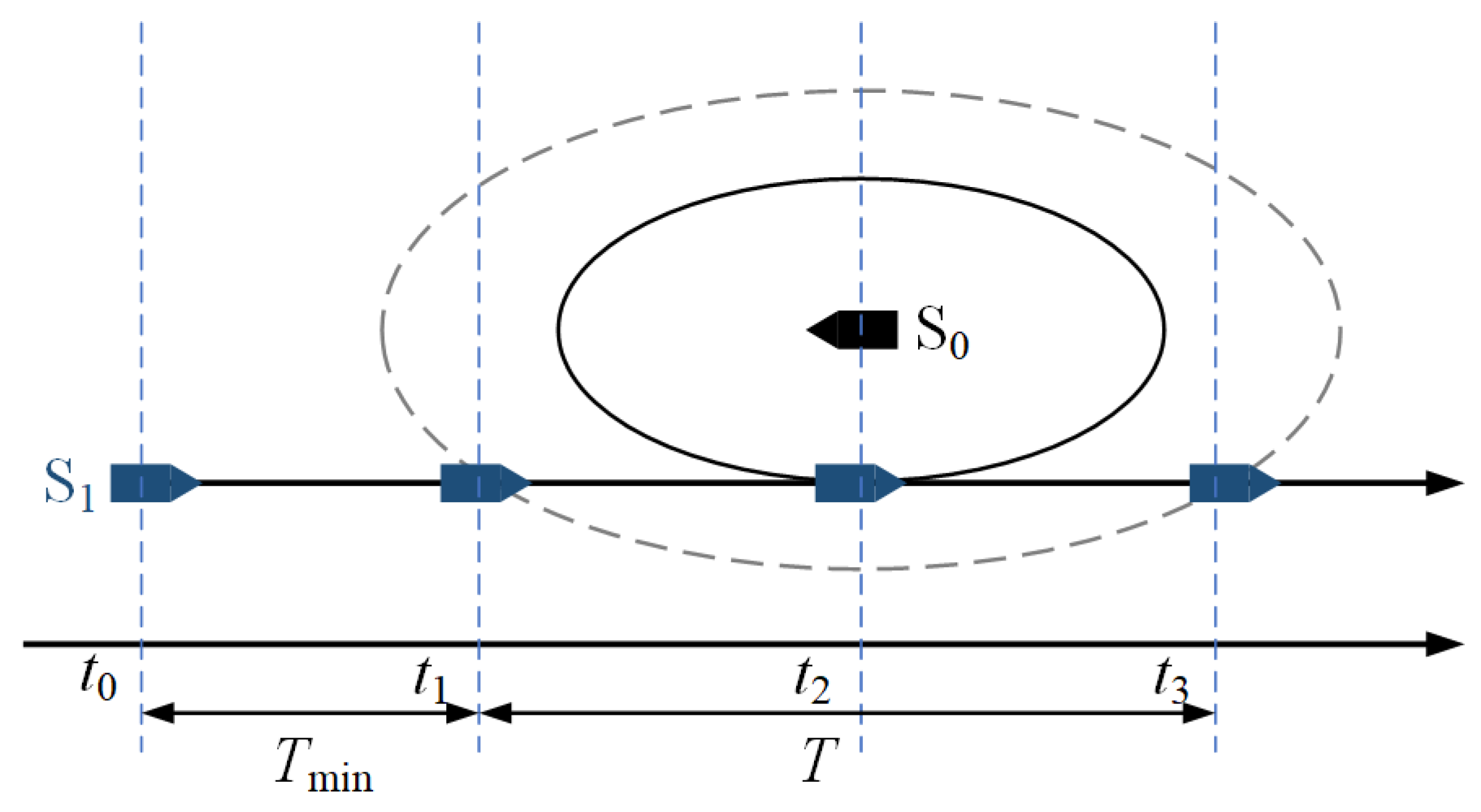
3.2.2. Elliptic Dynamic Ship Domain Calculation
- (1)
- When , , it indicates that TS’s invasion has ended.
- (2)
- When , , it indicates that TS’s invasion occurred at time and will end at time .
- (3)
- When , , it indicates that TS’s invasion has not yet occurred; it will invade OS’s domain at and leave the domain at .
3.2.3. The Improved CRI Model of the Ship Domain
4. Comparative Simulation of Ship CRI Models
4.1. Experimental Hypothesis
- (1)
- Ships encounter open waters with good visibility, and the influence of external environmental factors such as wind, waves, and currents are not considered.
- (2)
- OS size is only considered in the calculation of the ship domain, and OS length is ignored during other processing.
- (3)
- The minimum safety distance of the ship is set to 0.5 n miles, that is, . The process of perceiving the collision risk to making avoidance decisions to steering takes about 15 to 20 min. In this study, .
4.2. Comparison Simulation of the Improved CRI () and CRI ()
5. Conclusions
Author Contributions
Funding
Institutional Review Board Statement
Informed Consent Statement
Data Availability Statement
Conflicts of Interest
References
- Fuji, Y.; Shiobara, R. The Analysis of Traffic Accidents. J. Navig. 1971, 24, 534–543. [Google Scholar] [CrossRef]
- Szlapczynski, R.; Joanna, S. Review of Ship Safety Domains: Models and Applications. Ocean Eng. 2017, 145, 277–289. [Google Scholar] [CrossRef]
- Goodwin, E.M. A Statistical Study of Ship Domains. J. Navig. 1975, 28, 328–344. [Google Scholar] [CrossRef] [Green Version]
- Davis, P.V.; Dove, M.J.; Stockel, C.T. A computer simulation of marine traffic using domains and arenas. J. Navig. 1980, 33, 215–222. [Google Scholar] [CrossRef]
- Coldwell, T.G. Marine traffic behavior in restricted waters. J. Navig. 1983, 36, 430–444. [Google Scholar] [CrossRef]
- Sun, L. The Research on Mathematic Models of Decision-Making in Ship Collision Avoidance; Dalian Maritime University: Dalian, China, 2000. [Google Scholar]
- Liu, S. The Research of The Inland River Channel Transit Capacity where Ship is Crowed. Master’s Thesis, Dalian Maritime University, Dalian, China, 2002. [Google Scholar]
- Pietrzykowski, Z.; Uriasz, J. The Ship Domain—A Criterion of Navigational Safety Assessment in an Open Sea Area. J. Navig. 2008, 62, 93–108. [Google Scholar] [CrossRef]
- Pietrzykowski, Z.; Uriasz, J. The Ship Domain in A Deep-Sea Area. In Proceedings of the 3rd International Conference on Computer and IT Applications in the Maritime Industries, Siguenza, Spain, 9–12 May 2004. [Google Scholar]
- Hansen, M.; Jensen, T.; Lehn-Schiøler, T. Empirical Ship Domain Based on AIS Data. J. Navig. 2013, 66, 931–940. [Google Scholar] [CrossRef] [Green Version]
- Jia, C. Discussion on the Field of Ships in Crowded Waters. J. Dalian Marit. Univ. 1989, 4, 15–19. [Google Scholar]
- Xiang, Z.; Hu, Q.; Shi, C. Computation method of ship domains in restricted water based on AIS data. J. Transp. Eng. 2015, 15, 110–117. [Google Scholar]
- Smierzchalski, R.; Michalewicz, Z. Modelling of a ship trajectory in collision situations at sea by evolutionary algorithm. J. IEEE Trans. Evol. Comput. 2000, 4, 227–241. [Google Scholar] [CrossRef] [Green Version]
- Smierzchalski, R. On-line trajectory planning in collision situation at sea by evolutionary computation experiments. In Proceedings of the IFAC Conference on Computer Applications in Marine Systems, Glasgow, UK, 18–20 July 2001; pp. 84–89. [Google Scholar]
- Wang, Y.Y. An empirically-calibrated ship domain as a safety criterion for navigation in confined waters. J. Navig. 2016, 69, 257–276. [Google Scholar] [CrossRef] [Green Version]
- Guo, Z. Quantitative analysis of ship domain boundary. J. Wuhan Shipbuild. 2001, S1, 63–64. [Google Scholar]
- Wielgosz, M.; Pietrzykowski, Z. Ship domain in the restricted area—analysis of the influence of ship speed on the shape and size of the domain. J. Chin. J. Clin. Neurosurg. 2012, 36, 514. [Google Scholar]
- Dai, J.; Wang, D.; Liu, K. Calculation method of port restricted channel capacity based on ship domain model. J. Wuhan Univ. Technol. 2009, 33, 679–682. [Google Scholar]
- Jingsong, Z.; Zhaolin, W.; Fengchen, W. Comments on ship domains. J. Navig. 1993, 46, 422–436. [Google Scholar] [CrossRef]
- Zhou, D.; Zheng, Z.Y. Dynamic Fuzzy Ship Domain Considering the Factors of Own Ship and Other Ships. J. Navig. 2019, 72, 467–482. [Google Scholar] [CrossRef]
- Pietrzykowski, Z. Ship’s Fuzzy Domain—A Criterion for Navigational Safety in Narrow Fairways. J. Navig. 2008, 61, 499–514. [Google Scholar] [CrossRef]
- Pietrzykowski, Z.; Wielgosz, M. Effective ship domain—Impact of ship size and speed. Ocean Eng. 2021, 219, 108423. [Google Scholar] [CrossRef]
- Wang, N. An intelligent spatial collision risk based on the quaternion ship domain. J. Navig. 2010, 63, 733–749. [Google Scholar] [CrossRef]
- Wang, N. A novel analytical framework for dynamic quaternion ship domains. J. Navig. 2013, 66, 265–281. [Google Scholar] [CrossRef] [Green Version]
- Liu, Y.; Chen, H.; Hao, Y. A Risk-Degree Model of Collision Based on Fuzzy Theory. Navig. China 1998, 43, 25–31. [Google Scholar]
- Xu, Y.M.; Zhang, Y.L.; Shen, J.; Zou, C.; Guan, H.X.; Zhao, W. A Model of Ship Collision Risk Index Based on Fuzzy Set Theory. Ship Sci. Technol. 2021, 43, 82–87. [Google Scholar]
- Hu, Y.; Zhang, A.; Tian, W.; Zhang JHou, Z. Multi-Ship Collision Avoidance Decision-Making Based on Collision Risk Index. J. Mar. Sci. Eng. 2020, 8, 640. [Google Scholar] [CrossRef]
- Yu, J.; Liu, Z.; Zhang, X. DCA-Based Collision Avoidance Path Planning for Marine Vehicles in Presence of the Multi-Ship Encounter Situation. J. Mar. Sci. Eng. 2022, 10, 529. [Google Scholar] [CrossRef]
- Lee, H.J.; Rhee, K.P. Development of collision avoidance system by using expert system and search algorithm. Int. Shipbuild. Prog. 2001, 48, 197–212. [Google Scholar]
- Ahmed, Y.A.; Hannan, M.A.; Oraby, M.Y.; Maimun, A. COLREGs Compliant Fuzzy-Based Collision Avoidance System for Multiple Ship Encounters. J. Mar. Sci. Eng. 2021, 9, 790. [Google Scholar] [CrossRef]
- Liu, Z.; Wu, Z.; Zheng, Z. An Improved Danger Sector Model for Identifying the Collision Risk of Encountering Ships. J. Mar. Sci. Eng. 2020, 8, 609. [Google Scholar] [CrossRef]
- Chen, P.; Li, M.; Mou, J. A Velocity Obstacle-Based Real-Time Regional Ship Collision Risk Analysis Method. J. Mar. Sci. Eng. 2021, 9, 428. [Google Scholar] [CrossRef]
- Kijima, K.; Furukawa, Y. Design of automatic collision avoidance system using fuzzy inference. IFAC Proc. Vol. 2001, 34, 65–70. [Google Scholar] [CrossRef]
- Kijima, K.; Furukawa, Y. Automatic collision avoidance system using the concept of blocking area. IFAC Proc. Vol. 2003, 36, 223–228. [Google Scholar] [CrossRef]
- Lisowski, J. Determining the optimal ship trajectory in a collision situation. In Proceedings of the IX International Scientific and Technical Conference on Marine Traffic Engineering, Szczecin, Poland, 1 January 2001; pp. 192–201. [Google Scholar]
- Szlapczynski, R. A Unified Measure of Collision Risk Derived from the Concept of a Ship Domain. J. Navig. 2006, 59, 477–490. [Google Scholar] [CrossRef]


| Speed (Knots) | 5 | 6 | 7 | 8 | 9 | 10 | 11 | 12 | 13 | 14 | 15 | 16 | 17 | 18 | 19 | 20 |
|---|---|---|---|---|---|---|---|---|---|---|---|---|---|---|---|---|
| 5.270 | 5.674 | 6.042 | 6.381 | 6.697 | 6.995 | 7.276 | 7.544 | 7.799 | 8.045 | 8.280 | 8.508 | 8.727 | 8.940 | 9.146 | 9.347 | |
| 3.761 | 4.049 | 4.312 | 4.554 | 4.780 | 4.992 | 5.193 | 5.384 | 5.566 | 5.741 | 5.909 | 6.072 | 6.228 | 6.380 | 6.528 | 6.671 | |
| 2.417 | 2.648 | 2.863 | 3.063 | 3.253 | 3.433 | 3.605 | 3.770 | 3.929 | 4.082 | 4.231 | 4.375 | 4.515 | 4.651 | 4.784 | 4.914 | |
| 1.863 | 2.036 | 2.197 | 2.347 | 2.489 | 2.625 | 2.754 | 2.877 | 2.997 | 3.112 | 3.223 | 3.331 | 3.436 | 3.538 | 3.638 | 3.735 |
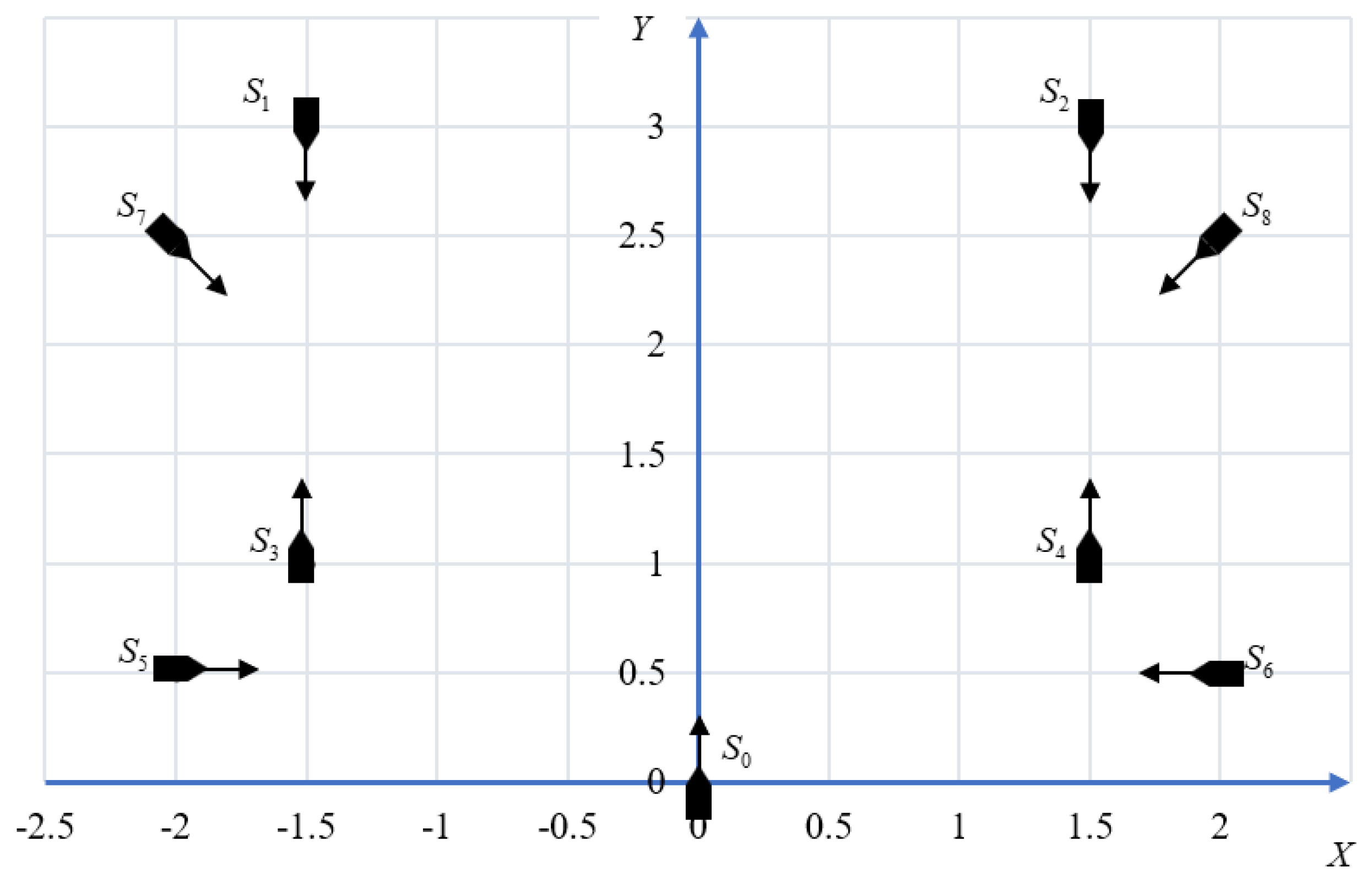
| Parameters | S0 | S1 | S2 | S3 | S4 | S5 | S6 | S7 | S8 |
|---|---|---|---|---|---|---|---|---|---|
| v (kn) | 10 | 10 | 10 | 8 | 8 | 10 | 10 | 10 | 10 |
| course (°) | 0 | 180 | 180 | 0 | 0 | 90 | 270 | 135 | 225 |
| X (n mile) | 0 | −1.5 | 1.5 | −1.5 | 1.5 | −2 | 2 | −2 | 2 |
| Y (n mile) | 0 | 3 | 3 | 1 | 1 | 0.5 | 0.5 | 2.5 | 2.5 |
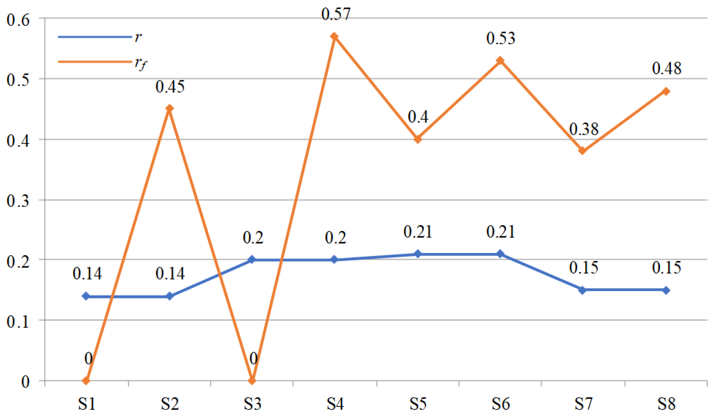
| Ship | DCPA/DS | TCPA | D/DS | r | fmin | Tmin | f(t) | rf |
|---|---|---|---|---|---|---|---|---|
| S1 | 3.00 | 9.00 | 6.71 | 0.14 | 1.86 | N/A | 2.88 | 0 |
| S2 | 3.00 | 9.00 | 6.71 | 0.14 | 0.87 | 8.36 | 1.89 | 0.45 |
| S3 | 3.00 | 30.00 | 3.61 | 0.20 | 1.86 | N/A | 2.01 | 0 |
| S4 | 3.00 | 30.00 | 3.61 | 0.20 | 0.87 | 7.28 | 1.02 | 0.57 |
| S5 | 2.12 | 7.50 | 4.12 | 0.21 | 0.68 | 7.66 | 2.90 | 0.40 |
| S6 | 2.12 | 7.50 | 4.12 | 0.21 | 0.51 | 2.98 | 1.43 | 0.53 |
| S7 | 1.78 | 9.99 | 6.40 | 0.15 | 0.38 | 10.01 | 3.39 | 0.38 |
| S8 | 1.78 | 9.99 | 6.40 | 0.15 | 0.31 | 5.89 | 2.01 | 0.48 |
Publisher’s Note: MDPI stays neutral with regard to jurisdictional claims in published maps and institutional affiliations. |
© 2022 by the authors. Licensee MDPI, Basel, Switzerland. This article is an open access article distributed under the terms and conditions of the Creative Commons Attribution (CC BY) license (https://creativecommons.org/licenses/by/4.0/).
Share and Cite
Li, W.; Zhong, L.; Xu, Y.; Shi, G. Collision Risk Index Calculation Based on an Improved Ship Domain Model. J. Mar. Sci. Eng. 2022, 10, 2016. https://doi.org/10.3390/jmse10122016
Li W, Zhong L, Xu Y, Shi G. Collision Risk Index Calculation Based on an Improved Ship Domain Model. Journal of Marine Science and Engineering. 2022; 10(12):2016. https://doi.org/10.3390/jmse10122016
Chicago/Turabian StyleLi, Weifeng, Lufeng Zhong, Yang Xu, and Guoyou Shi. 2022. "Collision Risk Index Calculation Based on an Improved Ship Domain Model" Journal of Marine Science and Engineering 10, no. 12: 2016. https://doi.org/10.3390/jmse10122016