1. Introduction
With the vigorous growth of target detection in computer vision, underwater target detection based on optical imaging plays an important role in fishery, aquaculture, underwater archaeology, marine military, and other fields [
1,
2,
3,
4]. In the field of marine fishery, traditional underwater frogmen fish and explore; they require a lot of equipment support and sufficient underwater experience, and they are also faced with life-threatening situations at any time. Long-term fishing operations lead to serious occupational diseases, and the cost of manual fishing operations is gradually increasing [
5]. Due to the limitation of fishing time and the impact of the marine environment, fishing operations provide great challenges. For example, the habitat of seafood is in the bottom of rocky reefs in the deep sea and in sediment with dense water and grass [
6]. It is a key task to adopt underwater object detection network algorithms to improve fishing accuracy.
Nowadays, with the rapid progress of Deep learning and its excellent performance in various fields, an increasing number of scholars are working on the use of deep learning methods in underwater target detection [
7]. However, due to the limitations of the marine environment, large-scale fishing equipment cannot be used in marine pastures. Nowadays, fishing operations are mainly carried out using underwater robots. Because of the limitation of real-time performance and the computing power of underwater equipment [
8,
9], large-scale networks cannot be deployed into underwater mobile equipment [
1]. However, there are few real-time and lightweight underwater target detection algorithms at this stage. Therefore, with the premise of ensuring detection precision, searching for ways to lighten the network and quicken the speed of detection has become an important part of subsequent research.
At this stage, there are two categories based on deep learning methods in the field of objection detection: one type is two-stage target obbjection algorithms that generate candidate bounding boxes, such as FastR-CNN [
10], FasterR-CNN [
11], Mask R-CNN [
12], etc. The candidate regions are generated by the network as target samples, then those samples with candidate regions are classified and edge regressed using convolutional neural networks. For example, Wei-Honglin used Roimix to simulate overlapping and blurred targets for enhancement based on the Faster R-CNN network, which effectively improved the detection accuracy [
6]. Fenglei Han proposed a CNN network to solve underwater image brightness by combining maximum RGB and grayscale images, and a new structure of DeepCNN was designed for classification regression prediction [
13]. The other type is regression-based one-stage object detection algorithms, such as the SSD algorithm [
14] and YOL-series algorithms [
15,
16,
17,
18]. The advantage of the one-stage algorithms over the two-stage target detection algorithms is better real-time capability, making them better suited to the needs of underwater fishing. For example, Minghua Zhang et al. used the multi-scale attention feature fusion (affm) [
19] module and Depthwise separable convolution based on YOLOv4 to lighten the network to improve the detection speed [
1]. Zhihua Liu et al. proposed a sample weighting network named SWIPENet, which improved the detection accuracy of small objects through high-resolution feature maps and a new sample weighting algorithm [
9].
Due to the degradation phenomenon caused by complex and changeable underwater scenes, the main forms of degradation are color distortion and blurring [
20,
21]. The image restoration of low-resolution images captured by underwater robots is a difficult question that needs to be handled. Improving image quality and color contrast can greatly improve overall detection accuracy. For image restoration, many scholars use the retinex [
22] and ssr algorithms for image restoration to decrease the influence of the incoming image on the reflection imaging of the object itself. The msr [
23] algorithm performs weighted fusion at different scales, then performs color balance and normalization on the results. Almahairi used the Cyclegan [
24] generative adversarial network to transfer style for image restoration. Li J. used the WaterGAN network for transfer learning through aerial images and noise vectors; however, this is considerably different from the real underwater images [
25]. When training in the neural network, this may have a negative impact on the overall sample, which is not conducive to the identification of real underwater scenes. Nan Wang used UWGAN [
26] for color recovery and defogging through U-NET to maintain similarity with the real scene. Whitening is a common method for underwater image restoration to restore the corrected offset colors.
The above works describes mainstream models and image restoration techniques in the field of underwater object detection, mainly aiming at a lightweight neural network and to solve the image blur caused by poor underwater imaging conditions and serious underwater robot visual jitter [
6,
27]. However, in our research we found that the large number of small targets in underwater images and the diversity of marine organisms led to the issue of missed detection in final recognition. The living habits of echinus, scallops, holothurians, and other marine organisms lead to coincidence and the dense distribution of targets, which makes the model have a low detection accuracy during prediction. With regard to the above questions, we chose the newer YOLOX algorithm in the YOLO family of one-stage object recognition algorithms as the base network for this paper. In contrast with the other object recognition networks of the YOLO series, the YOLOX algorithm adopts double-head decoupling and the anchor free algorithm to enhance the object detection velocity of the object detection network, which is more applicable to underwater detection and identification. We propose a network suitable for underwater object detection, which we name B-YOLOX-S. Several key points of our work are shown below:
1. The use of Poisson Matting to solve the negative impact of large differences in the various of categories in the dataset on the network. By clipping and screening the target anchor boxes of each category and then merging to achieve data amplification, the recognition ability of the network is improved.
2. We propose using the Haar wavelet transform [
28] for image restoration work. Different filters of the Haar wavelet pool are used for pooling processing to solve the large differences in image color caused by different water and different lighting conditions and the blurring of underwater images.
3. A new connection method of the neck layer is proposed. We propose a BIFPN-S algorithm, which retains the details of the image through a bidirectional feature extraction network to deal with the issue of low accuracy of small object detection. Moreover, in this paper we advance the multi-scale feature fusion performance of the network by fusing it with FPN to enhance the detection network’s ability to detect targets at different scales.
4. We use EIoU_Loss as the localization loss function in this paper to make the prediction box closer to the ground truth box, thereby accelerating the convergence speed and heightening the localization precision of the network.
2. Related Works
2.1. The YOLOX Algorithm
The YOLOX [
29] algorithm contains four models: the YOLOX-s, YOLOX-m, YOLOX-l, and YOLOX-x algorithms.
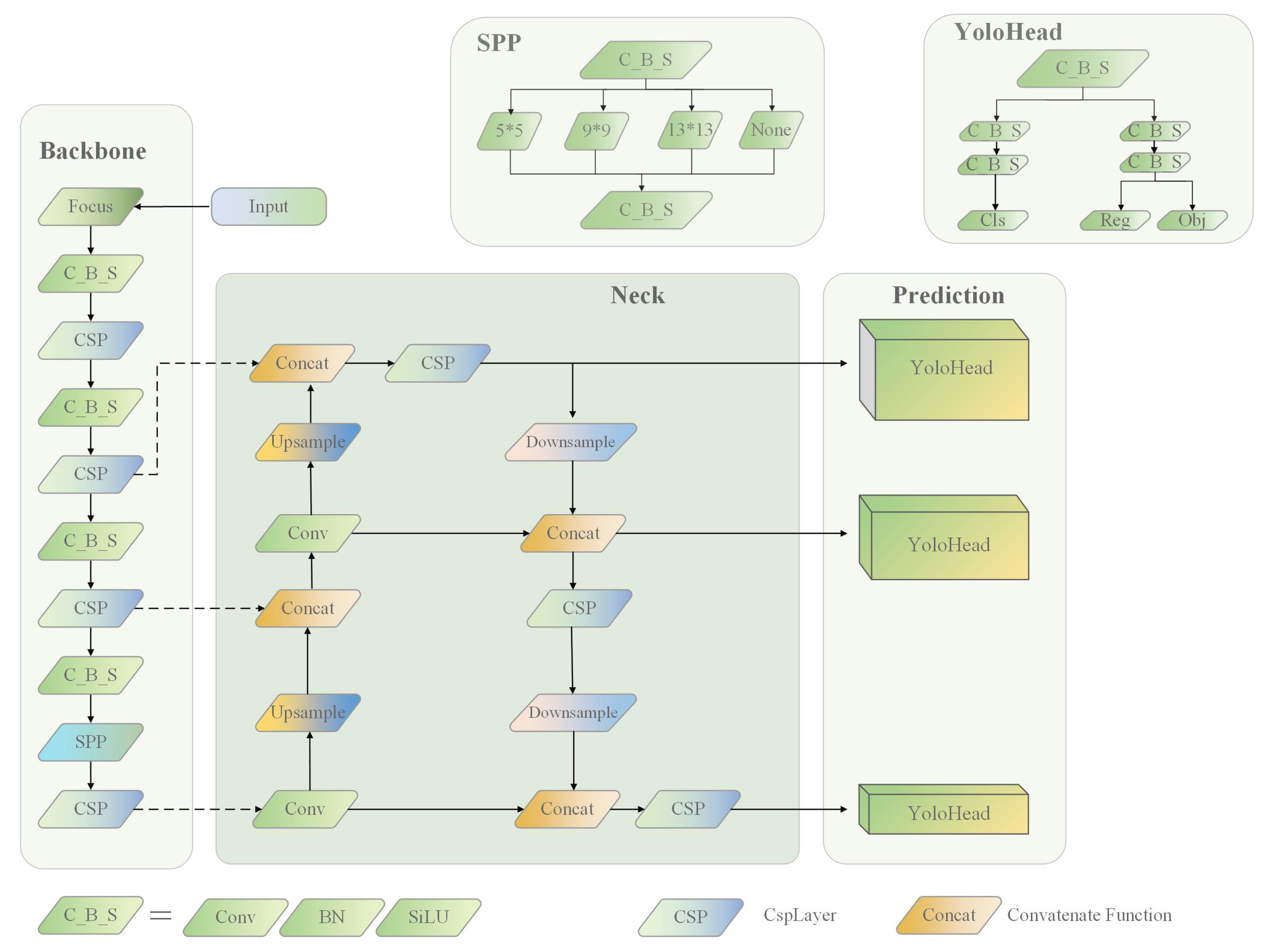
Figure 1 shows the structure of the YOLOX-s network, which is the least computationally intensive algorithm in the YOLO series, and is chosen as the base algorithm for this paper to better meet the needs of mobile hardware platforms deployed in underwater robots. Its channel scaling factor depth is 0.33 and its layer scaling factor width is 0.5. However, using the lightweight YOLOX-s algorithm suffers from poor recognition accuracy for underwater obscured targets and small underwater targets that cannot achieve accurate positioning performance.
Input layer: The methods of mosaic [
18] data augmentation and Mixup [
30] data augmentation are mainly used.
Mosaic data enhancements improves the algorithm by randomly scaling four photos, flipping left and right, and changing the color gamut of image saturation, tones, and brightness to enrich the dataset. Then, the processed photos are randomly distributed together to enhance the data in order to further strengthen the network’s learning of small targets and blocking targets.
Mixup: A new image is obtained by filling the two images up and down and left and right, respectively, and then performing weighted fusion.
Backbone layer: The backbone feature extraction network of YOLOX uses the Darknet53 network structure with a Spatial Pyramid Pooling (SPP) [
18] structure. The image of the input network is first extracted from the Cross-Stage Partial (CSP) Darknet to obtain the information of three feature layers, the three effective feature layers are transmitted to the Neck layer for feature enhancement. Using the focus network structure, four independent feature layers are obtained and then stacked to make sure the input channels are quadrupled.
Focus: By slicing the image, a value is obtained for every pixel in a picture, similar to neighborhood downsampling, resulting in four pictures. In this way, the W and H information is pooled into the channel space, and the input channels are expanded by a factor of four. By stitching and stacking them, the image becomes twelve channels, compared to the original RGB three-channel mode. Finally, the new image is convolved to obtain a two-fold downsampled feature map without information loss.
Neck Layer: As an enhanced feature extraction module in a YOLOX algorithm, the three feature layers obtained by the backbone feature extraction network are used for feature fusion in this layer. The detailed and semantic information of each effective feature layer is obtained by fusing the feature information of each scale in different feature layers. The PaNet (Path Aggregation Network) model is employed, which achieves feature fusion by upsampling and downsampling in the form of Feature Pyramid Networks(FPN) [
31] + Pixel Aggregation Network (PAN) [
18].
Prediction layer: In this case, classification and regression are performed in the YOLOX network using the YOLO head. The feature map transmitted from the Neck layer is judged by the corresponding feature points. The presence of objects in these feature maps, the type to which they belong and the object’s corresponding position information (x, y, w, h) are detected. Compared with the previous YOLO series, the YOLOX algorithm uses an anchor-free decoupled head in this layer.
YoloHead: Classification and regression were fused together in the single decoupled head used in the YOLO family of algorithms prior to the YOLOX algorithm. However, the focus of classification and regression tasks in YOLOX is different. Classification is mainly based on which category the extracted features belong to, while regression focuses more on parameter correction with the ground truth box details through the positioning loss function. Therefore, classifying and regressing the same feature map has an effect on the results, resulting in inaccurate positioning and classification [
32]. In YOLOX, the YOLO head implements classification and regression separately, and finally fuses them together in the prediction stage.
Anchor-free: Unlike the anchor-based approach used by the previous YOLO network, the anchor box [
33] is no longer used in YOLOX [
34]. Taking the input size of 640 × 640 as an example, the parameters of the anchor-based algorithm are three feature maps of 80 × 80, 40 × 40, 20 × 20, and each feature map has three anchor boxes corresponding to each pixel. Each anchor box has a number of data set types n, coordinate and attribute information x, y, w, h, and type information, for a total of n+5 parameters. The parameters used by the anchor-based algorithm are 3 × (80 × 80 + 40 × 40 + 20 × 20) × (n + 5) = 25,200 × (n + 5) prediction boxes. The anchor-free approach includes all prediction boxes in a feature map through multiple decoupling heads, meaning that its parameter quantity is (80 × 80 + 40 × 40 + 20 × 20) × (n + 5) = 8,400 × (n + 5). There are three scales of 8 × 8, 16 × 16, and 32 × 32 anchor size prediction boxes; thus, the number of parameters obtained using this method is reduced by nearly two thirds.
2.2. Data Augmentation
Although Deep Learning has performed well in the field of computer vision, a large number of training samples are required for training deep learning-based neural networks. However, using a small number of training samples is inadequate to support network training, leading to overfitting [
35]. Due to the particularity of target detection, if geometric transformation is directly used, the processing of the ground truth box can affect the accuracy of network detection [
36,
37,
38]. The use of data augmentation techniques can solve the above-mentioned drawbacks and heighten the robustness of the target recognition network without the added complexity of network inference. To enhance the adaptability of the target detection network in different scenarios and strengthen the robustness of target detection, many scholars have devoted themselves to researching image enhancement. The complex and changeable habitat environment of marine organisms, the numerous small underwater targets, and the severe disturbance of negative samples such as topography, rocks, and coral reefs mean that choosing which strategy to adopt in order to enhance data in underwater target detection has become a difficult problem.
In recent years, many scholars have used Cutmix [
39], Cutout [
40], and Mixup [
30] to enhance images in order to obtain satisfactory training results. Chunhe Song et al. improved the robustness of model recognition using Gaussian blur and image rotation for UAV transmission line inspection [
41]. In the Pascal VOC Challenge, the Ali Turing Lab proposed using the instance-balanced augmentation method to augment the dataset. First, the original image is magnified by one point five times to obtain the sample image, then the initial size is taken as the smooth window to translate the sample image horizontally and vertically three times. During the parallel shift process, different disturbance rules are used to obtain nine images of equal size to the original image for data augmentation. Kisantal et al. solved the problem of small target numbers through oversampling, then used the copy–paste strategy to augment the target class objects to perform data augmentation in order to advance the detection performance of their Neural Network [
42]. However, the current data enhancement methods do not deal well with obfuscation and overlap of underwater targets [
43]. Therefore, this paper uses the Poisson matting technique combined with style migration to solve the above problem from the perspective of data augmentation.
3. Materials and Methods
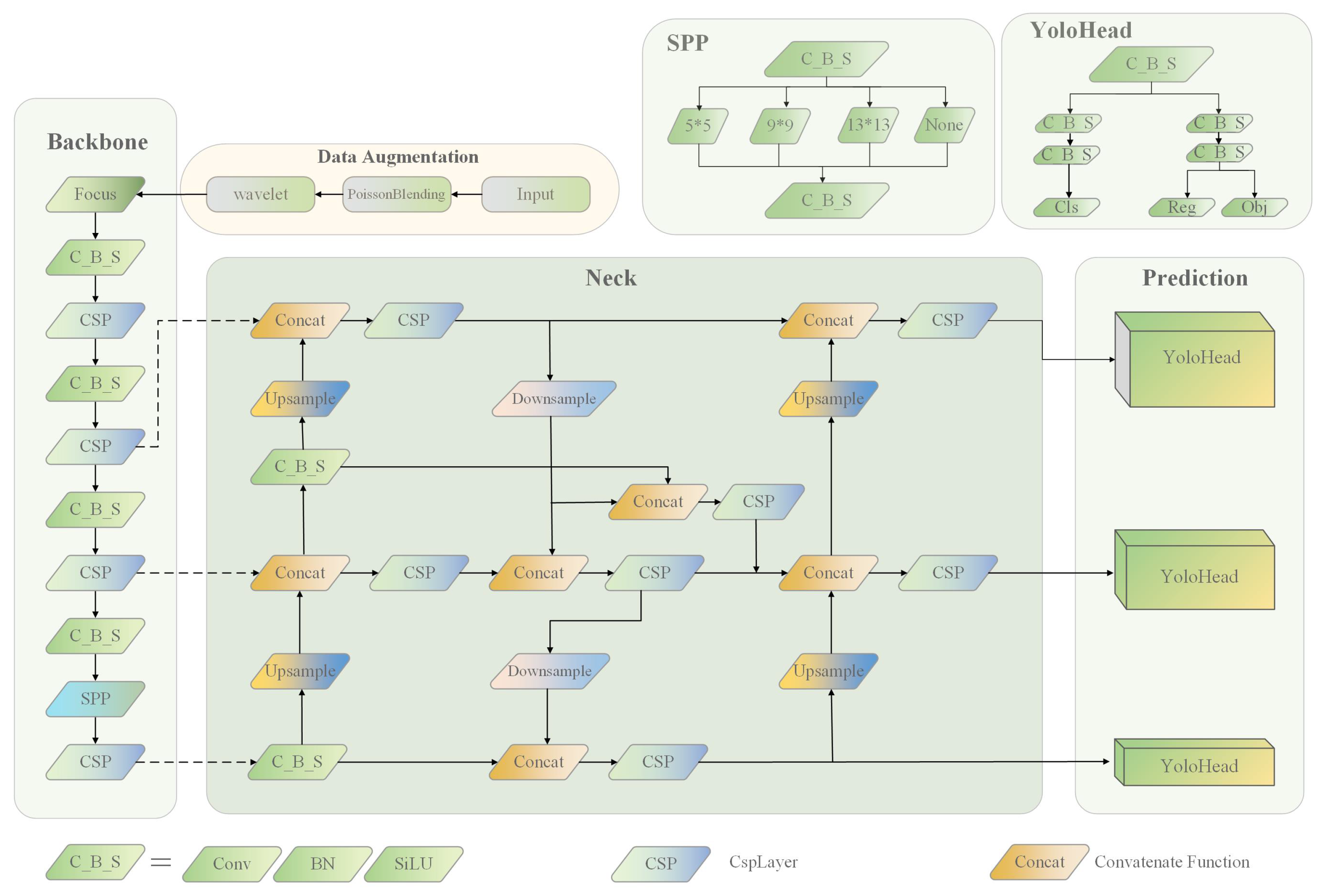
This section details the dataset used in this paper and the proposed object detection algorithm. The improved B-YOLOX-S model structure is shown in
Figure 2. First, the input end performs Poisson matting to complete data augmentation, then performs style transfer and image restoration processing through wavelet transform. After processing, the image is compressed to a resolution of 640 × 640 and input to the backbone layer of the network. Then, through feature extraction of the original image through the backbone network, three feature layers of 80 × 80, 40 × 40, and 20 × 20 are obtained. The three effective feature layers are transmitted to the Neck layer. The FPN + BIFPN-S module performs upsampling, downsampling, and multi-scale feature fusion on three different scale feature layers. Finally, the three effective feature layers after fusion are transmitted to the prediction layer of the network, and classification and regression prediction are performed through the decoupled head. The methods and datasets are described in detail in the following sections.
Section 3.1 mainly deals with the statistical analysis of the URPC dataset used in this paper.
Section 3.2 shows the data augmentation method from the two aspects of data augmentation and image restoration.
Section 3.3 and
Section 3.4 introduce our proposed feature fusion module and the localization loss function, respectively.
3.1. URPC Dataset
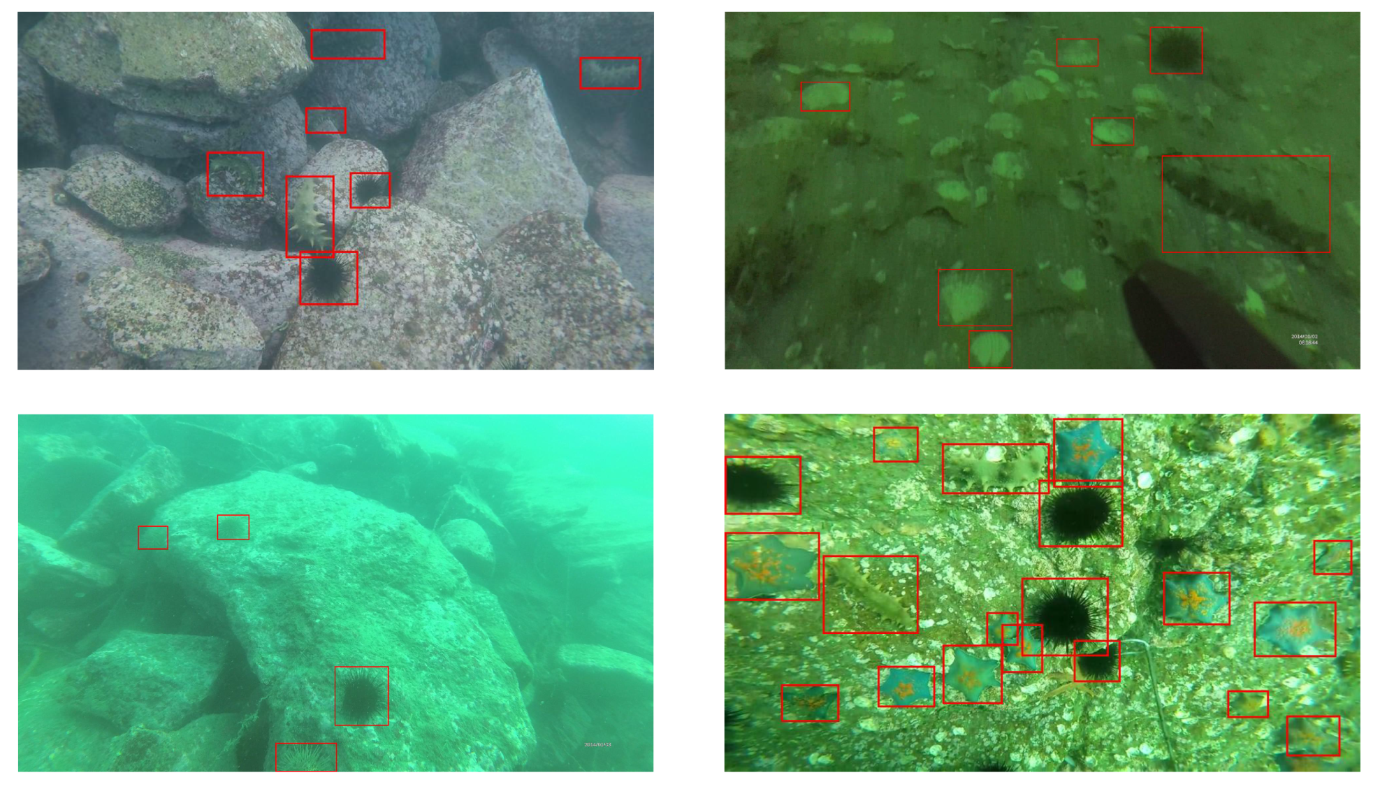
The dataset utilized in this paper was the public URPC2020 dataset, which was provided by Pengcheng Lab for use in the optical event of the underwater target detection algorithm of the Underwater Robotics Competition 2020. Sample data of this dataset are shown in
Figure 3. It contains target images of different waters, different geographical environments, and different lighting conditions.
The dataset contains 5543 underwater images, of which the categories in the dataset are echinus, scallop, starfish, and holothurian. Examples of ground truth boxes corresponding to each category are shown in
Figure 4.
The results of our analyses and the statistics of the URPC2020 dataset are shown in
Table 1:
The ‘Numbers’ column in
Table 1 represents the number of images corresponding to different resolution images. In this dataset, the number of images with an aspect ratio of 1 is 34,039, the number with an aspect ratio of 2 is 6585, the number with an aspect ratio of 3 is 717, the number with an aspect ratio of 4 is 82, the number with an aspect ratio of 5 is 12, the number with an aspect ratio of 6 is 2, and the number with an aspect ratio of 7 is 3.
3.2. Data Augmentation Strategy
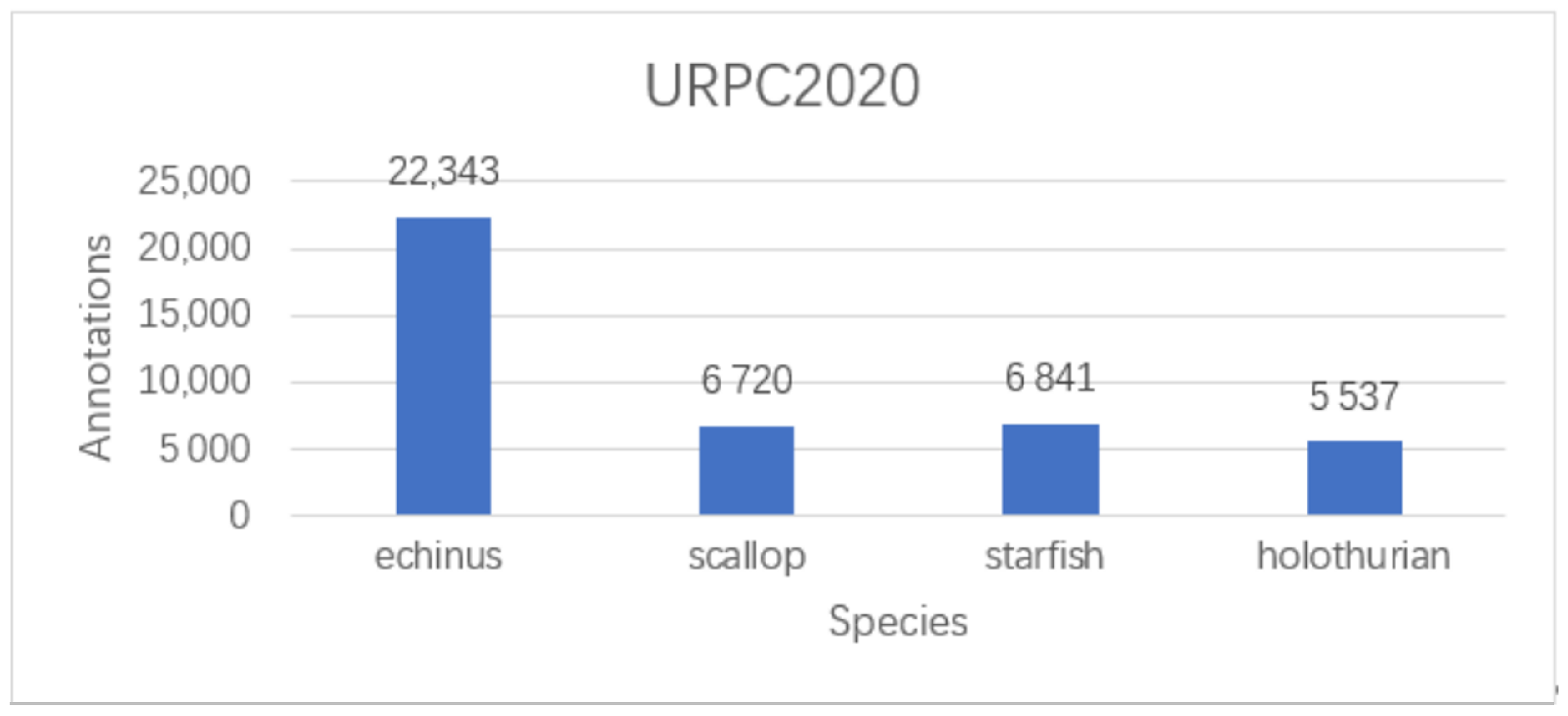
Through our analysis of the URPC2020 dataset and previous experiments with this dataset, we found the number corresponding to each category and its imbalance, as follows: echinus, 18,676; scallop, 5554; starfish, 5704; and holothurian, 4574. Insufficient training samples and class imbalance can lead to poor detection performance of the model [
42]. Sample augmentation is needed to balance the effect of the number of each sample category [
44]. Furthermore, the color of the water column varies widely under different light and water conditions. When the robot is shooting underwater, data energy is lost due to the absorption of light signals via the scattering effect of suspended substances in the seawater [
45]. The scattering of interfering light in the optical path leads to poor quality of the captured images and the occurrence of blurring and distortion blocking [
46]. Therefore, image restoration of underwater images is one of the key tasks of this paper. Finally, this paper uses the Poisson matting method to perform data augmentation operations on the dataset. This approach was used to handle the imbalance in the number of category samples in the UPRC2020 dataset. Then, wavelet transform was used to transfer the style of the images of different waters in the enhanced dataset to complete the image restoration work.
Section 3.2.1 and
Section 3.2.2 respectively introduce the implementation steps and core algorithms of Poisson fusion and image restoration through wavelet transform.
3.2.1. Poisson Matting
In Poisson matting, the content of the source image is indiscriminately fused to the target image without difference, instead of simply superimposing the pixel contents of the two images that need to be fused [
47]. The intrinsic approach is to ensure that the boundary pixels of the target image are guided by the gradient field of the target part of the source image during fusion; then, the pixels of the fusion region are generated. The source image passes its gradient field to the target image. Then, the target image is fused by its own characteristics through the gradient field of the target where the source image is located. The overall requirement is to keep the target part of the source image as similar as possible to the pixels generated in the fused region in the gradient field. This is reflected in the process of solving the mathematical equation to minimize the gradient difference as much as possible, thus minimizing the problem, as described by Equation (
1):
In Equation (
1),
represents the source image,
f indicates the pixel value of the source image,
represents its gradient value,
represents the pixel value of the target image,
v denotes the gradient of the original image, and
represents the source image boundary. The calculation of the gradient value is shown in Equation (
2), and the calculation of the divergence value is shown in Equation (
3).
where div is expressed as the divergence of the vector field and
x,
y represent the two gradient directions of the two-dimensional image.
To make the target image fus into the original image more realistically, the boundary of the generated region needs to be consistent with the boundary value of source images in the fusion region, that is, the Laplacian results of the two should be as consistent as possible. In solving Eqeuation (1), the solution with the smallest change is the solution of Poisson’s equation, such as Equation (
4), which is the Laplace equation satisfying the Dirichlet boundary condition:
In Equation (
4),
is the Laplacian operator.
We randomly cropped the category targets according to the label positions corresponding to the XML files in the dataset. The targets were categorized and filtered, and the blurred and incomplete images were eliminated to form a category dataset. When analyzing the categories in the original dataset, we found that the amount of echinus categories is significantly higher than other categories. Therefore, we retained the target number of echinus as a constant and performed Poisson matting of scallops, holothurians, and starfish to achieve data augmentation and to enhance the learning performance of our network.
The target in the above category template was randomly rotated and scaled to match the original image. The gradient fields of the category image and the image to be enhanced were calculated using a differential approach, and the extent of the category image was adjusted according to the target size in different resolutions in the dataset. The gradient fields of the enhanced images were processed using a mask; that is, a layer of mask was covered on the gradient field tensor of the enhanced image to select the location tensor of the region of interest. Gradient field fusion was performed on the masked gradient field and the category image. Convolution was performed using a Laplace convolution kernel to compute the scatter field of the fused image in order to compute the value of the equation BX = a. For the construction of the sparse matrix B, as shown in Equation (
5), each row of the matrix has five non-zero elements, corresponding to the convolution kernel of the Laplace algorithm; the value of its diagonal position is −4, and in each row the corresponding four non-zero elements in its adjacent positions have a value of 1.
Solving BX = a, a is the divergence of the image, as shown in Equation (
5). The equations are solved for each of the three channels in the image separately. Then, the corresponding pixel R-value, G-value, and B-value of each point are obtained, and the pixel values of the resulting X are replaced by the pixel at the fused position. Finally, the fused image and the XML file corresponding to the label position is generated.
In Equation (
6), the
value, the
value, and the
value are the matrix of the sought X. The right part of the equation is the scatter value of the source image, which is a.
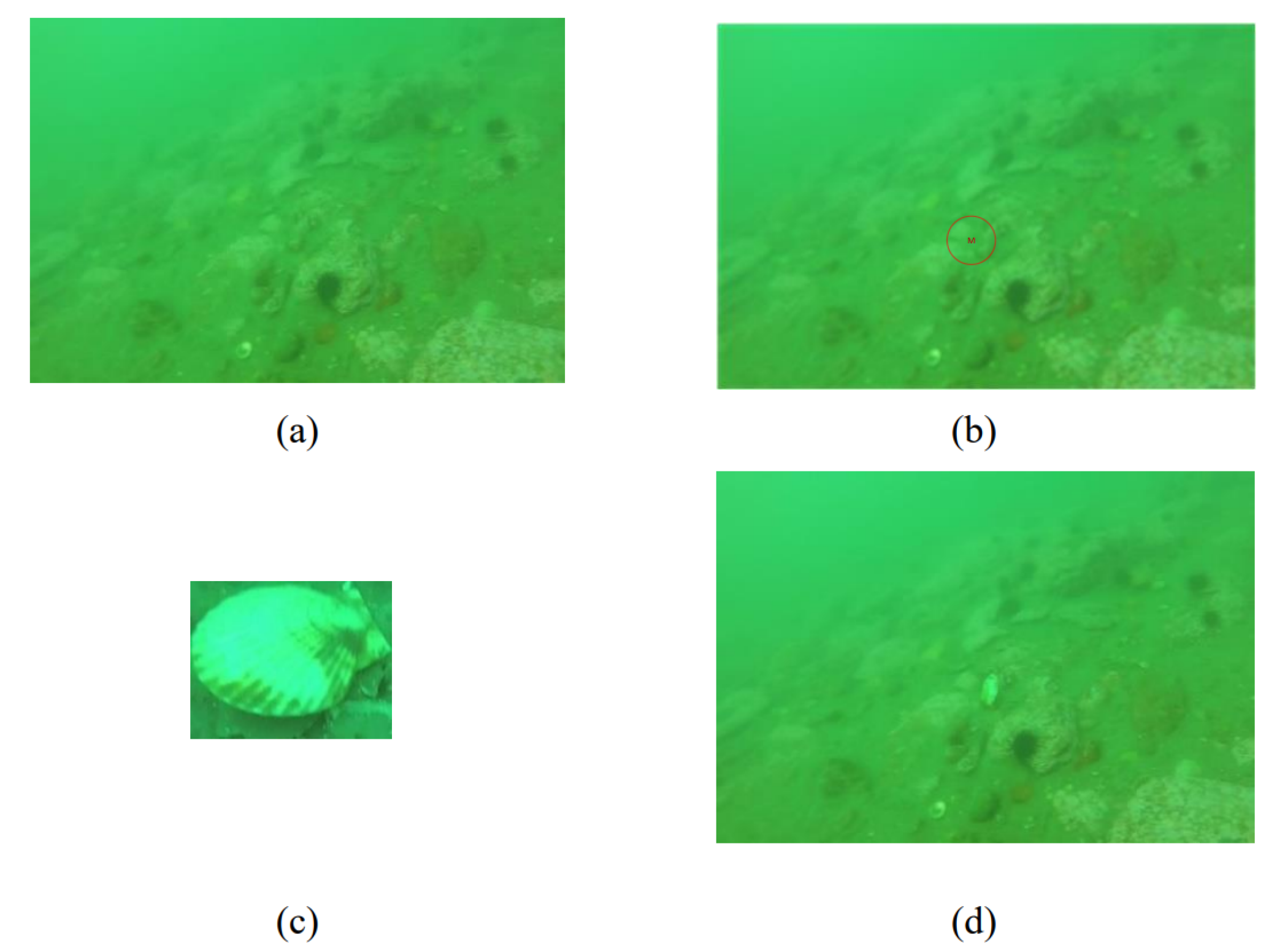
Taking the scallop enhancement as an example, we calculated the gradient value of each pixel of the background image in the category dataset. Point M was used to specify the enhanced position of the scallop template image in the background image, where point M is the center position of the scallop template, as shown in
Figure 5b. The specified target category ’scallop’ is selected from the category dataset, and the scallop image is matched with the original image. The gradient field of the fusion area is calculated, and the pixel R, G, and B values of the fusion point are obtained and replaced, as shown in
Figure 5d.
3.2.2. Image Restoration Based on Wavelet Transform
Underwater images exhibit an initial blue-green tint due to absorption of red wavelengths, as well as scattering from suspended matter, resulting in image distortion and blurring. In this paper, image restoration was performed on real images captured by underwater robots and the processed underwater images were Poisson matted without relying on any physical model. We used a novel encoder–decoder structure, using wavelet correction transformation as a network module through this network structure to perform style transfer learning and image restoration on underwater images with different colors and from different waters. Through high fidelity image recovery to improve global contrast, the impact of noise on images was decreased and degraded and distorted images were recovered and enhanced to keep the original details of the image.
Through singular value decomposition (SVD), the style information in the image was removed, the overall structure information of the image was retained, and pixel de-correlation, which is a whitening transformation, was realized. Coloring transformation was used to perform the inverse transformation of the whitening change. The image was then divided by the maximum pixel value of 255 to make its pixels between [0, 1]. Then, average subtraction was performed for each pixel in the image, centering at 0 to render each pixel value in the image. The eigenvalues needed to perform SVD were obtained by computing this 0-centered covariance matrix. The transformation equation is shown in Equation (
7):
where
B consists of the left singular vector,
A consists of the singular values of the normalized dataset covariance, and
Y is the normalized dataset, which is the hyperparameter responsible for controlling the whitening effect.
The Haar wavelet transform was used to restore the spatial signal without any amplification of noise, and style transfer was performed on the image. The Haar wavelet pooling operation has four sub-bands, which are composed of the high-frequency and low-frequency filters LLT, LHT, HLT, and HHT, respectively, as shown in
Figure 6. In this paper, we used a low frequency sub-band (LL) to capture smooth surface and texture information in images. The high frequency sub-bands (LH, HL, HH) were used to acquire edge information.
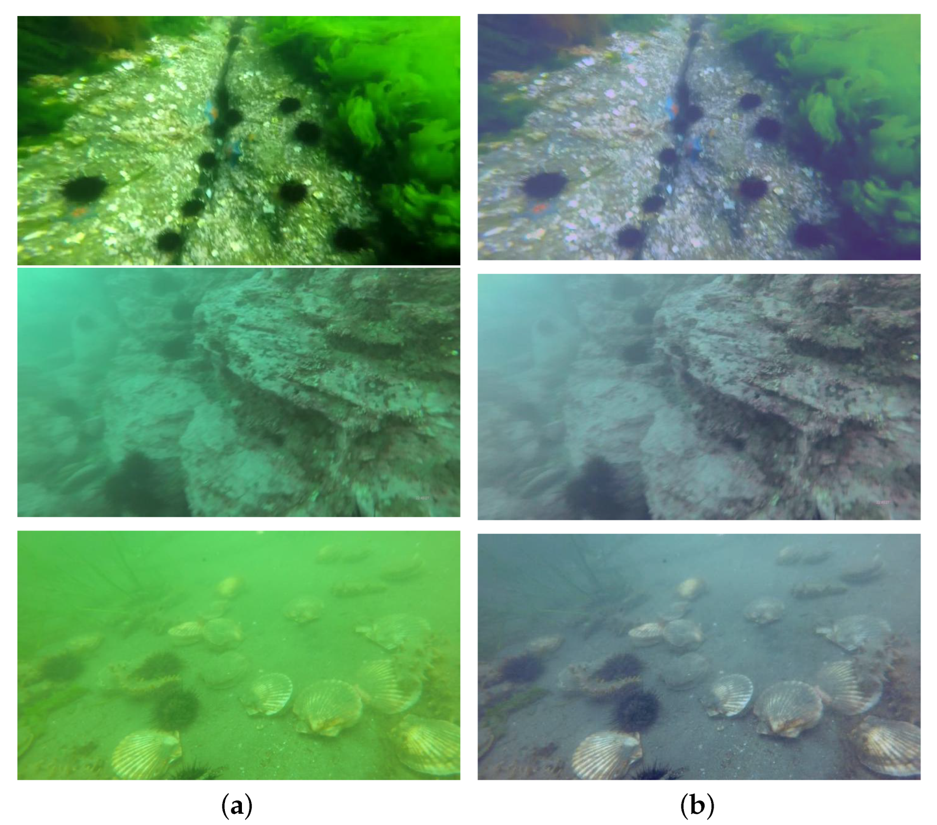
The semantic information captured using the low-frequency filter is passed to the next encoder module, while the high-frequency filter is directly connected with the decoder module. This method was used to prevent the loss of spatial information caused by the use of upsampling and maximum pooling, and to ensure high fidelity during image recovery. The mirror operation of wavelet pooling is a de-pooling operation. By convolving and summing the components, the primeval signal can be reconstructed with minimal noise amplification, which helps to preserve the structural information of the image and can help in performing style transfer and image restoration. Under the conditions of different waters, different depths, and different light scattering, the color and clarity of underwater images changes as well.
Figure 7 shows the comparison image before and after processing using the wavelet transform.
3.3. Strengthening the Feature Fusion Module
Based on the BiFPN algorithm proposed in EfficientDet [
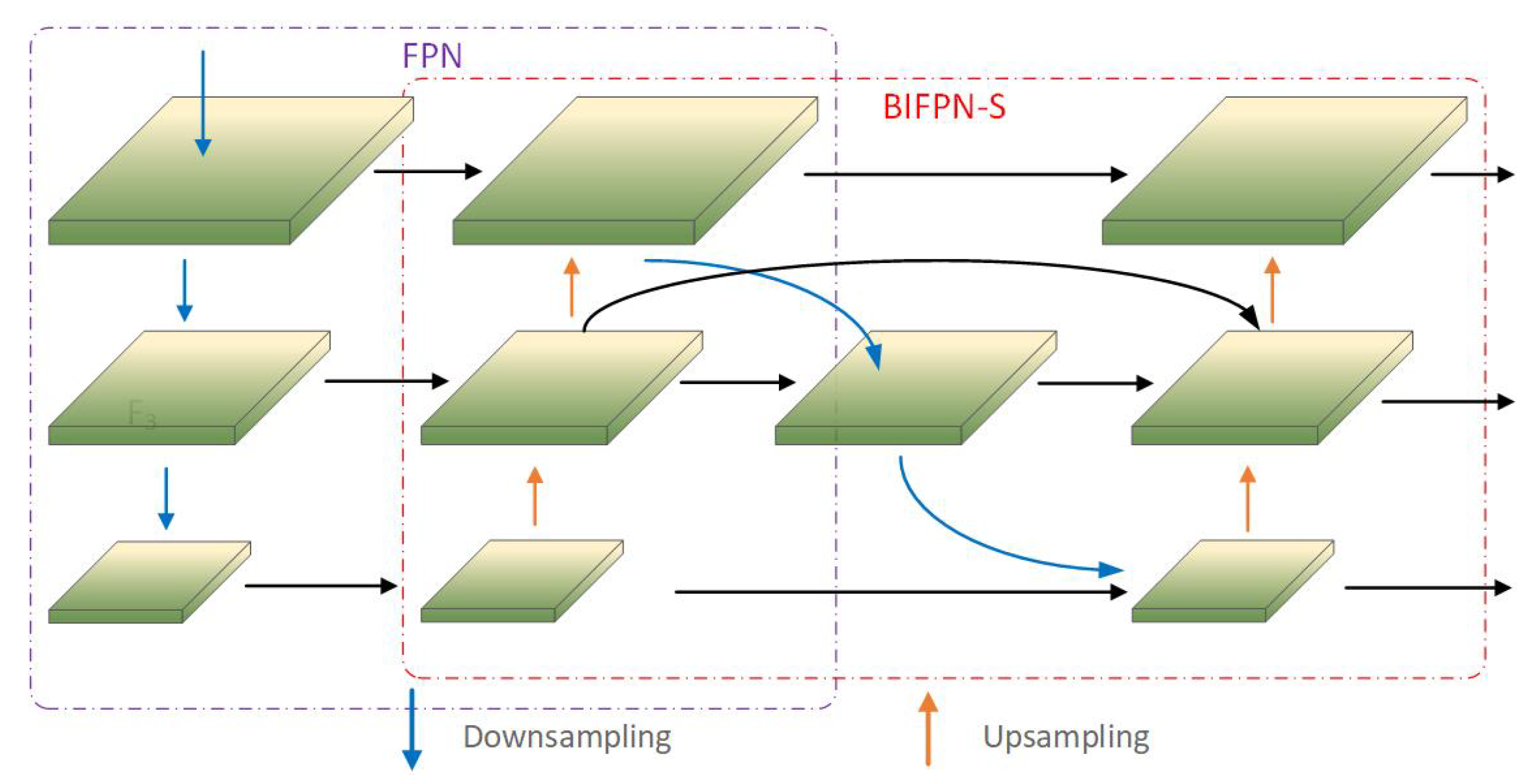
48], this paper proposes a highly efficient multiscale feature fusion algorithm, BIFPN-S, adapted to the YOLOX network, as shown in
Figure 8. First, the semantic information of the high-level feature maps was amplified using two layers of upsampling. Then, the texture features of the feature map were retained through two layers of downsampling to reduce the amount of computation. The detailed information of the mid-level feature map was preserved using a jump connection, and multi-scale feature fusion was performed. Finally, the feature maps were mapped to the target size after two layers of upsampling.
The BIFPN-S algorithm is a bi-directional feature pyramid network which is able to avoid a sharp drop in detection accuracy when detecting small objects, thereby preserving the image details in the underlying model. We used multi-scale feature fusion to extract higher-level semantic information through bottom-up downsampling, then used top-down upsampling to combine the feature map with high-level semantic information with the previous feature layer. This feature fusion was performed to provide information on different semantics and expand its recognition of objects with different resolutions. In the YOLOX network itself, nodes without feature fusion are removed to simplify the model of the network in order to accelerate the detection speed of the model. The feature map with high-level semantics uses the connecting edges from the original node to the final output to ensure stability of detection. The location information of the feature map is enhanced via multi-scale fusion through BIFPN-S to ensure more accurate positioning. Because FPN is mainly aimed at the enhancement of semantic features, it does not transmit the positioning information in the feature map, which affects the precision of object detection. FPN is used for fusion with the proposed BIFPN-S, allowing the strong localization features of BIFPN-S to fuse with the high semantic features of FPN. Ultimately, the detection speed and the detection precision of the enhanced feature extraction network are considerably improved compared with PanNet itself.
The proposed BIFPN-S algorithm was integrated into the YOLOX network, and its network structure is shown in
Figure 9. The original image is extracted to three feature layers through the CSPDarknet backbone network, then residual processing is performed by FPN to enhance feature extraction. The three enhanced effective feature layers are transmitted to the BIFPN-S algorithm for enhanced feature fusion, which better preserves the semantic information of the image.
3.4. Localization Loss Function
The loss function was calculated to compare the predicted results of the network with the true results. In the model of this paper, the loss function is composed of three components:
1. reg: determines the regression parameters of the feature points, then uses the prediction box and the ground truth box to calculate the IoU_Loss.
2. obj: determines whether the feature points contain objects. The feature points homologous to the ground truth box are all positive samples; otherwise, they are negative samples. A prediction is made as to whether the feature points of the over positive and negative samples contain objects to calculate the loss.
3. cls: judges the type of objects contained in the feature points. The calculation of loss is performed according to the prediction boxes of the kinds of feature points and the kinds of ground truth boxes.
As far as IoU is concerned, it is determined by the ratio of the area of the intersection of the predicted box and the ground truth box to the combined total area. However, IoU ignores the problem of unbalanced bounding box regression. A large number of boxes with little overlap with the anchor box plays a major role in the positioning of the bounding box. A loss function based on IoU leads to slow convergence and inaccurate regression positioning. Therefore, this paper uses EIoU_Loss as the positioning loss function.
The EIoU_Loss [
49] is an improvement of the localization calculation based on the CIoU_Loss. However, CIoU_Loss only considers the aspect ratio of the rectangular box, which ignores the difference in the confidence of the width and length itself, as in Equation (
8):
The definition of the value of v is shown in Equation (
9), and the gradient value of the width w and height h is shown in Equation (
10):
Because of the relative ratio of width and height used by CIoU_Loss, it can be seen from
that the gradients of
w and
h have opposite signs in value; that is, when one value of
w and
h increases, the other value decreases, and they cannot increase and decrease at the same time. When performing regression, if both
w and
h are larger than the detection target, if
h is larger than the target while
w decreases,
h needs to expand, resulting in a decrease in the convergence speed. Therefore, EIoU_Loss adds the side length loss (Lasp) to its loss function, and directly predicts
w and
h, to a certain extent, in order to solve situations in which the side length is wrongly amplified. Finally, EIoU_Loss modifies the aspect ratio part of CIoU_Loss to calculate the loss function separately for length and width. This modification makes the network more accurate in localization, and measures the overlapping area, side length, and center point, as shown in Equation (
11):
EIoU_Loss divides the loss function into the three components of IoU loss
, distance loss
, and side length loss
. The calculation of IoU is shown in Equation (
12), where
and
represent the height and width of the rectangle, respectively, for calculation of the localization loss function when the ground truth box and the prediction box coincide, that is, when the intersection ratio = 1 and the loss = 0. At this time they both have a high degree of coincidence, as shown in Equation (
13).
4. Experiments and Results
4.1. Experimental Environment and Training Parameter Settings
Table 2 shows the experimental environment configuration of this paper. The Pytorch version 1.7.0+cu101 deep learning framework was used, with an Intel(R) Core (TM) i7-9700 CPU @ 3.00 GHz, 16G memory, 2080 NVIDIA GeForce GTX graphics cards, and Windows 10 operating system; the software programming environment was Python 3.6.
The URPC2020 dataset training and test sets were divided following a ratio of 9:1. Among them, the training set contains 4988 pictures and the test set 555 pictures. The training set was then divided into 499 images in a 9:1 ratio for use as the validation set. During model training, there are four categories: echinus, scallop, starfish, and holothurian. In this paper, the pre-trained weights of the VOC dataset were used for the training of B-YOLOX-S. Because the YOLOX network requires a fixed input size, we set the input image resolution to a uniform 640 × 640. In the training process, a total of 100 epochs were set for training, and the confidence and non-maximum threshold (nms_iou) were set to 0.5. To make the network more capable during feature extraction and ensure the stability of the weights, the backbone layer was frozen for the first 50 epochs to accelerate the training efficiency of the network, then unfrozen for the last 50 epochs. During this time, the parameters of the network change. During training, the original figure of the learning rate of the first 50 groups was adjusted to 0.001 and the initial value of batch_size was adjusted to 32; while for the last 50 groups the value of the learning rate was set to 0.0001 and the value of batch_size to 16.
We ensured that there were pictures taken in different waters and under different lighting conditions in the training set, test set and validation set. There is obvious blurring in the images caused by camera shake when the underwater robot is shooting and by the underwater optical imaging conditions; the low-resolution images captured by the underwater robot are more blurred, and it is difficult to identify the target. Moreover, the label positions in the dataset are not accurate, and many targets are missed through manual labeling. Therefore, data enhancement was mainly performed on images with a resolution less than or equal to 720 × 405.
4.2. Evaluation Indicators
In this paper, representative evaluation indicators commonly used in target detection models are used, namely, the AP, mAP, and FPS parameters.
AP (Average Precision) reflects the average recognition accuracy of the model for each class. The AP value is approximated using a smoothing operation by calculating the area of the P–R(Precision–Recall) curve, with recall as the horizontal axis of the coordinate system and precision as the vertical axis of the coordinate system and the coordinate axis.
mAP (mean Average Precision) reflects the average AP value of all categories. In this paper, mAP50 and mAP75 are used to evaluate the model. For mAP50, the detection precision of the model had an IoU (Intersection over Union) threshold of 0.5, while for mAP75 the detection precision of the model had an IoU threshold of 0.75. mAP is one of the most important indicators of the target detection evaluation model, and is shown in Equation (
14):
In Equation (
14),
m is the individual category in the dataset, while
refers to the average detection accuracy corresponding to each category.
Parameter represents the number of parameters convolved in the network.
FPS (Frames Per Second) represents the number of images recognized in one second.
Apec, APho, APsc, and APst represent the AP values of echinus, holothurian, scallop, and starfish, respectively, with the IoU threshold set to 0.5.
4.3. Experimental Results
In
Section 4.3.1, we combine the proposed method with the YOLOX base network to conduct ablation experiments. In
Section 4.3.2, the validity of our model is verified by comparison with other mainstream models.
Section 4.3.3 presents our results and analysis on the URPC dataset.
4.3.1. Ablation Experiments
We conducted ablation experiments on the YOLOX-s network to visualize the better performance of the proposed method in underwater target detection and the effectiveness of each method. The ablation experiments were mainly performed at the Input layer, the Neck layer, and the Prediction layer of the model. To ensure the uniformity of the validation, the first 50 groups of experiments were used to freeze the backbone layer for training, and the last 50 groups were used to unfreeze the training.
This paper describes the following experiments conducted on the network. On the input of the network, the first step was to test the impact of the Poisson matting algorithm and our proposed wavelet transform algorithm on the model. In the second step, the two data enhancement algorithms proposed above were combined for comparative detection. For the Neck layer of the network, we verified the detection effect using the enhanced feature fusion algorithm BIFPN-S proposed in this paper, referred to here as Bs. For the Prediction layer, we sought to detect the influence of EIoU_Loss, used as the localization loss function in this paper on the model. The ablation experimental results are shown in
Table 3, where Apec, APho, APsc, and APst represent the AP values of echinus, holothurian, scallop, and starfish, respectively, with the IoU threshold set to 0.5
Table 3 shows the Poisson matting and the wavelet transform that were performed on the dataset; the verification analysis in the basic network of YOLOX-s shows that mAP increased by 2.86% and 1.87%, respectively. By combining the Poisson matting algorithm and the wavelet transform algorithm, the average detection accuracy improves by 3.5%. It can be seen from the comparison of mAP values that the data enhancement method used at the input end in this paper achieves considerable improvement in underwater target detection and recognition. For the Neck layer, with the replacement BIFPN-S algorithm proposed in this paper, the mAP is improved by 1.93% in our model, a slight increase, which reveals the applicability of the algorithm. By adding the EIoU_Loss module, the detection precision is increased by 1.87% and the detection speed is augmented without increasing the model parameters. This proves that modification of the localization loss function of YOLOX-s improves the recognition ability and detection rate of the model in complex environments. When combining the BIFPN-S algorithm proposed in this paper with the EIoU module, the mapping of this method on the dataset is 2.87% higher than without data augmentation. At the same time, the number and size of model parameters increases only slightly, and the training speed and training memory requirements of the improved network remain basically unchanged. The B-YOLOX-S algorithm proposed in this paper combines YOLOX-s with Poisson matting, wavelet transform, BIFPN-S, and EIoU_Loss. With only a slight increase in model size and the number of parameters, there is only a small decrease in detection speed and an increase of 5.05% in detection accuracy. Although the FPS is reduced, it continues to satisfy the demand of real-time recognition.
4.3.2. Comparison with Other Object Detection Algorithms
Table 4 shows the experimental results with the initial two-stage algorithm FasterR-CNN and the one-stage algorithms YOLOV3, YOLOV4, YOLOV5-s, YOLOX-s, and B-YOLOX-S (our proposed model). In this experiment, the input scale resolution of all models was 640 × 640. The results of calculation and comparison of the Parameter, Backbone, AP, mAP50, mAP75, and FPS indicators of different models in the URPC2020 dataset are shown in
Table 5.
From the analysis in
Table 5, the parameter value in our proposed B-YOLOX-S is obviously lower than in FasterR-CNN, YOLOV3, and YOLOV4, and slightly higher than YOLOV5-s in terms of model size; thus, it is easy to deploy on mobile platforms for detection and identification using underwater robots on the seabed. Taking FPS as the evaluation index to measure the target detection speed by comparing the FPS of different models, it can be concluded that the detection speed of the one-stage models is significantly higher than that of the two-stage model, and the detection speed of the B-YOLOX-S model is significantly faster than those of YOLOV3 and YOLOV4. While it is slightly slower than the YOLOV5-s model, it can nonetheless achieve real-time detection. Taking the mAP value and AP value as the indicators to measure the detection accuracy and using mAP50 as the evaluation indicator, the average detection accuracy of YOLOX-s are 4.3%, 3.7%, 2.22%, and 5.81% higher than other models, respectively. However, it is 5.05% lower than B-YOLOX-S. Comparing the results of mAP75, it can be intuitively seen that when the IoU threshold is 0.75, the detection accuracy of YOLOX-s shows good performance, which is significantly higher than others model by 20.87%, 19.58%, 12.97%, and 20.42%, respectively, and just 2.84% lower than our proposed model.
Based on the analysis of the AP values of echinus, holothurian, scallop, and starfish in
Table 5, it can be concluded that the detection accuracy of YOLOX-s has considerable advantages. This has many practical applications, and was our reason for selecting YOLOX-s as the basic model in this paper. Comprehensive analysis of the mAP value and AP value shows that the B-YOLOX-S network proposed in this paper has advantages in high-precision detection and a high detection accuracy pair, which is 2.84% higher than YOLOX-s. The mAP value and single category AP at the IoU thresholds of 0.5 and 0.75 are higher than the other models. The demonstrated accuracy of our method is the best among the other methods in terms of detecting target category occlusion and overlap. In summary, it can be seen from the comparative experiments that although there is a slight gap between the B-YOLOX-S and YOLOV5-s networks in terms of model size and detection speed, the detection accuracy of the former is significantly higher than other mainstream target detection algorithms, and it is more capable of meeting the needs of underwater target detection. Through the above comparative experiments, the validity and practicability of our model are verified.
4.3.3. Experimental Results on the URPC2020 Image Dataset
Through the above experiments, we compared the detection products of the YOLOX-s network and the B-YOLOX-S network on the URPC2020 dataset. We mainly show the detection images in the following two complex situations.
1. Detection of images in dense and overlapping states
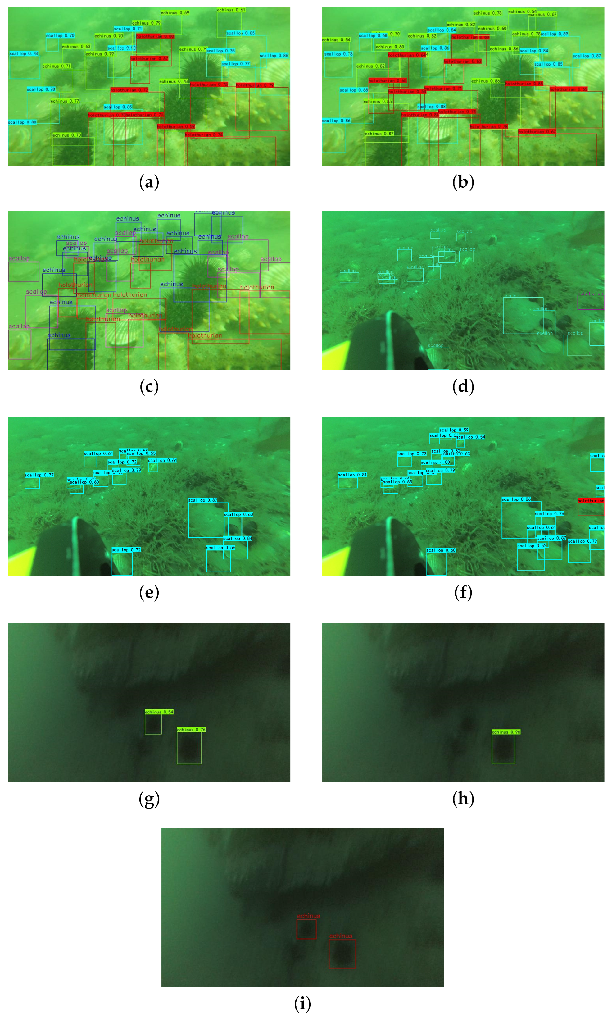
By comparing the underwater images in different dense and overlapping states, the detection results of image (a), image (b), and image (c) in
Figure 10 can be seen. When the targets of each category have serious overlap, the prediction box detected by B-YOLOX-S network is similar to the ground truth box, and the number of false detections is significantly smaller than that of the YOLOX-s algorithm. The analysis of image (g), image (h), and image (i) shows that the classification accuracy and localization accuracy are higher in the case of blurred environments and image distortion, and the miss detection rate is significantly lower than that of the YOLOX-s algorithm. Through the analysis of image (d), image (e), and image (f), it can be concluded that due to the influence of the target object’s habitat, for example when there are a large number of categories that are not part of this dataset, such as aquatic plants, reefs, and other factors that block a large area of the target object, the YOLOX-s algorithm detects only fifteen targets, which is four targets away from the ground truth box. Ours model, on the other hand, detects the real objects that are not observed through the artificially annotated ground truth box, which has practical application significance.
2. Small target detection in images including complex terrain
By comparing small target detection in images involving complex underwater terrain, the detection results of image (a), image (b), and image (c) in
Figure 11 are analyzed. The original YOLOX-s algorithm detects only two targets, while the algorithm in this paper detects a total of six targets with accurate positioning, no missed detection, and no false detection targets. In contrast, YOLOX-s has a high missed detection rate and inaccurate positioning of small targets in complex underwater scenes. Comparing the detection results of small targets in different waters, such as image (d), image (e), and image (f) in
Figure 11, the B-YOLOX-S algorithm detects a total of thirteen targets, the same as the ground truth box. The YOLOX-s model detects a total of nine targets, and misses two echinus targets. From this experiment, it can be concluded that the data augmentation algorithm used in this paper has good generalization in different waters. In analysing the detection results of image (g), image (h), and image (i), when the small target object is occluded, the model in this paper misses two targets and has no false targets, while the original YOLOX-s model misses four targets and incorrectly detects submerged rocks as echinus. Analysing of the detection results of image (g), image (h) and image (i), in which there are a lot of water plants and reefs in the water environment, the model in this paper accurately detects all targets, while YOLOX misses two targets. In cases in which the scallop targets are small and have a high similarity with the reef, the model in this paper demonstrates better recognition performance. Under the influence of various negative factors, using the multi-scale enhanced feature fusion module in our proposed model leads to a much lower miss rate and higher detection precision than the initial network.
In summary, the results of the B-YOLOX-S model are obviously better than those of the YOLOX-s model in the detection experiments in different scenes, and the recognition effect in different waters is significantly improved. In particular, the detection rate and error recognition rate are lower and more accurate in cases of target overlap, dense distribution, more small target categories, external occlusion, and image distortion, which illustrates the validity of our work.
6. Conclusions
In this paper, we propose a real-time detection algorithm, B-YOLOX-S, for underwater objects. First, the Poisson matting method is used to solve the differences in the amount of samples in the dataset, then style transfer and image restoration through wavelet transformation are used to achieve generalization in different waters. We propose a BIFPN-S multi-scale feature fusion network and combine it with FPN to reinforce the information extraction capability of the network for feature maps and to retain the detailed information of images. Aiming at the problem of accurate positioning of dense and overlapping targets, we use EIoU_Loss as a loss function to improve the precision of localization. The experimental data prove that the B-YOLOX-s algorithm performs well in sophisticated environments, such as those involving different water and lighting conditions. In the recognition of small underwater objects, the detection network proposed in this paper shows higher detection precision and recall rate along with a lower missed detection rate and false detection rate. Compared with the YOLOX-s algorithm, the AP values on the echinus, holothurian, scallop, and starfish categories are increased by 2.8%, 7.1%, 10.03%, and 1.21%, respectively. The lightweight model proposed in this paper is small in terms of parameters and easy to deploy on underwater vehicles for real-time detection and identification in fishing operations. In our next work, we intend to study a target detection model with higher recognition accuracy that can guarantee detection speed.


