Article

Simulation Modeling of a Ship Propulsion System in Waves for Control Purposes

1
Department of Industrial Engineering (DII), School of Polytechnic and Basic Sciences, University of Naples “Federico II”, 80125 Naples, Italy
2
Department of Mechanical, Energy, Management and Transportation Engineering (DIME), Polytechnic School, University of Genoa, 16145 Genoa, Italy
*
Author to whom correspondence should be addressed.
J. Mar. Sci. Eng. 2022, 10(1), 36; https://doi.org/10.3390/jmse10010036
Submission received: 13 December 2021 / Revised: 26 December 2021 / Accepted: 27 December 2021 / Published: 31 December 2021
(This article belongs to the Special Issue Smart Control of Ship Propulsion System)

Abstract

:
The article deals with a simulation approach to the representation of the ship motions in waves, interacting with the propulsion system behavior (diesel engine and propeller). The final goal is the development of a simulator, as complete as possible, that allows the analysis of the main engine thermodynamics in different sea conditions, also in the unfavorable event of dynamic instability of the hull, and the correct management of the other propulsion components. This latter aspect is particularly interesting in some of the last new energy solutions for decarbonization of ships, concerning, for example, auxiliary electric motors, powered by batteries, to support the traditional diesel-mechanical propulsion (especially in heavy weather conditions). From this point of view, a proper analysis of the engine dynamic performance, affected by particular sea states, is fundamental for a smart management and control of shaft generators/auxiliary electric motors, batteries, etc. To this end, the work presents and highlights the main features of a ship simulator, suitable for the study of the new propulsion solutions that are emerging in maritime transport. Some representative results will point out the complex non-linear behavior of the propulsion plant in waves. Moreover, a parametric roll scenario will be investigated, in order to highlight the capability of the conceived simulator in modeling the effects of the dynamic instability of the hull on the propulsion plant.

1. Introduction

Marine time-domain simulation has traditionally found its main use in the field of ship maneuverability, especially for the development of training simulators, which have become increasingly effective with the advent of virtual reality [1]. However, the scientific literature shows that dynamic simulation techniques have also been significantly adopted in ship design, although the most representative industrial applications are just only from the last twenty years. This is essentially due to the enhancement of computers and the development of particular commercial software for a more user-friendly application. In this framework, Genoa University was a pioneer in the development of simulators for evaluating the ship propulsion performance and analyzing pertinent machinery control logics [2]. A first significant example of a ship propulsion simulation with a full-scale validation is reported in [3]. It concerns the mechanical diesel propulsion system of a cruise ferry, while [4] proposes again the same approach to the validation of the methodology in the case of a small naval vessel. After the presentation and validation studies of the simulation method, Genoa University developed the first simulators for industrial applications in the cases of the aircraft carrier Cavour [5,6] and the Italian Navy Multi-Mission Frigates (FREMM) [7,8,9]. In both projects, real-time simulation was used to design and test the propulsion control system. The collaboration with the Italian Navy continued in the development of a simulation study for the propulsion system refitting of the tall ship Amerigo Vespucci (in this case, the square sail’s behavior was reproduced too [10,11]). These three applications represented a typical use of simulation in the design stage of a vessel, although it can also be used to evaluate the performance decay of already operating systems. In this regard, References [12,13] show simulation approaches to the representation of malfunctions/faults of marine engines and auxiliary systems for the thermal energy recovering from the exhaust gas of the engines. In the same research field, References [14,15,16] propose different simulation techniques (e.g., neural networks) for the marine engine diagnostics, while [17,18,19] show further examples of dynamic simulation approaches to the design of the ship energy systems
Focusing on marine propulsion systems, a good simulator is made up of several numerical sub-models that represent the main elements involved in ship propulsion. Surely, the main mover model can strongly characterize the complexity of the simulator as it can be faced with different approaches. Specific programming languages [20,21,22,23,24,25] or commercial software [26,27,28,29] can represent the engine behavior, with different levels of accuracy, according to the different purposes. On the contrary, the propeller is traditionally modeled by numerical tables, unless you want to describe further aspects, such as the dynamics of the rotation of the blades in the case of a controllable pitch propeller [30]. For other types of marine thruster, such as waterjet or cycloidal propellers, more complex models can be adopted [31,32,33]. Another important sub-model of the simulator certainly concerns the representation of the ship motions, which can be simulated with one [3,34], three (e.g., typical maneuverability simulators [35,36,37]), four [38] up to six degrees of freedom (DOF) [39]. Obviously, the complexity of the modeling grows in relation to the DOF number increasing. Moreover, different mathematical approaches may turn out to be more or less suitable for representing the motions of the ship at high or low speed (e.g., dynamic positioning applications [40]).
Due to the complexity of the whole ship dynamics, it is very difficult to develop a complete propulsion simulator taking into account both hull motions and main engine behavior. The whole ship dynamics in the time domain is usually studied by six DOF numerical models based on the equations of the rigid body motions. Several methods for the assessment of ship dynamic instabilities and maneuverability in waves have been extensively studied and compared [41,42]. However, all these numerical approaches disregard the propulsion power delivered by the main engine and rather assume ideal constant propeller revolutions or assume constant ship speed.
Several approaches of hull-propeller-engine interaction are available in the technical literature, although they mainly focus on the effects of the added resistance in waves, as underlined by [43]. In particular, in [43] the authors propose an interaction model of hull-propeller-engine by combining experimental data and numerical simulation in regular seas.
In [44], the simulation of the propeller performance accounts for the propeller emergence in waves, calculated beforehand from the estimation of ship motions in a head sea. The importance of developing a numerical model accounting for ship dynamics effects on the marine propulsion system performances has been recently pointed out in [45,46]. These research works account for simplified modeling of ship dynamics by means of a linear transfer function of heave and pitch and includes wake and propeller characteristic variations in regular waves.
Differently from the others, the present work shows a complete simulation approach to the description of the interaction between ship motions (six DoF) and machinery (i.e., prime mover and propeller), applicable in irregular sea, by combining the most sophisticated sub-models available in the state of the art, for a comprehensive simulation.
Indeed, the numerical model for ship dynamics is based on the so-called hybrid or blended non-linear approach, as described by [47,48].
Differently from [47], implemented in FORTRAN, the model adopted herein is developed and implemented in MATLAB/Simulink [49,50]. Similar to [47,51,52], it allows for the estimation of ship dynamic instabilities and maneuvering simulations in irregular waves with a fair level of accuracy. The main innovation of the present work is the interaction among the different propulsion components, in the presence of different sea states, accounting also for the possibility of simulating critical behaviors of the hull, such as dynamic instabilities. The weather conditions, in fact, greatly affect the hull motions, which, in turn, influence the behavior of the propeller and therefore the propulsion system. A constant wake factor in irregular sea is assumed, while ship speed changes because of the time-varying added resistance and propeller thrust.
The proposed simulation approach, described in its several sub-models, can become a useful tool for evaluating any critical issues on the engine, to be solved through appropriate control strategies. For the current application, a Ro-pax ship sailing in irregular sea is under investigation, assuming a thermodynamic model of a four-stroke medium diesel engine [53]. The results of several operational conditions are presented in order to point out the need for consistent interaction among the different sub-models for a proper depiction of the phenomena.

2. Numerical Model of the Simulator

The developed simulator aims at connecting existing sub-models of ship dynamics in irregular seas and a diesel engine, accounting for propeller actions in waves. The following subsections describe in brief each sub-model. The whole simulator is implemented in the MATLAB/Simulink platform.

2.1. Ship Dynamics in Wave

The numerical six DoF model for ship dynamics in waves (in the time domain) included all forces and moments acting on a sailing vessel in irregular sea. The hull surface was discretized by means of triangular panels up to the freeboard deck. Mass and inertia actions included all non-linear coupling terms of the rigid body dynamics. All non-linearities regarding hull geometry were accounted for in the calculation of Froude–Krylov and restoring actions.
Radiation forces and moments were implemented by means of the convolution integral technique, while diffraction forces and moments were obtained by linear superposition of regular wave components. The regular force components, which were the input data for both radiation and diffraction actions, were taken from potential strip theory calculations, carried out beforehand [54].
Additional details together with validations of the implemented numerical model, regarding ship motions and accelerations in waves, are available in [49]. It is worth noting, that the ship speed, in the reference applications, was set as constant, thus no attention was given to the effects of added resistance in waves (in addition to ship resistance in still water), which represents a demanding second-order problem [55].
In the current form of the simulation model, the ship resistance curve in still water was given as input data, while added wave resistance accounted only for first-order effects. In general, this approach could lead to approximate results, especially in the range of small wave components (i.e., smaller than ship length), where radiation and diffraction actions are predominant and the numerical modeling for these forces is not suited to the added wave resistance problem. On the other hand, the current approach provided quite accurate restoring and Froude–Krylov non-linear components, that for long waves (i.e., longer than ship length) became predominant.
Therefore, limiting the case studies to sea states characterized by a wavelength greater than ship length, this numerical model can be considered suited at the scope of the paper.
A brief validation of the model is presented in Table 1 for the hull KVLCC2, extensively studied for benchmark researches [56]. The experimental data (exp) available for this ship [56] concerned the speed reduction in regular waves given a fixed propeller revolution. The numerical simulations were carried out, including propeller actions but neglecting engine contribution. The obtained speed reduction in wave (sym) was compared against the experimental speed data.
As expected, the comparison of the results disclosed that the error on the speed reduction in waves decreased with wavelengths (λ) longer than ship length L. For this range of wavelength, the error remained below 10%.

2.2. Propeller Actions

The numerical model of the sailing ship in waves included screw propeller actions that were implemented by means of still water propeller coefficient KT and KQ, given as a function of the advance coefficient J. Propeller thrust has to balance ship resistance in waves, while propeller torque has to be balanced by the torque provided by the engine. The wake and the thrust deduction factors for modeling the propeller-hull interaction in irregular sea, refer to the still water condition.
The thrust Tprop and the torque Qprop at the propeller were obtained as follows:
Tprop = ρKT*Nprop2Dprop4  Qprop = ρKQ*Nprop2Dprop5
In Equation (1), KT* and KQ* are modified propeller coefficients in order to account for a propeller operating very close to the free surface due to the wave effects. In particular, the simulation approach proposed by [57], for modeling generalized ventilation losses, was used. According to [57], thrust and torque ventilation loss factors (βtv and βqv, respectively) can be introduced:
KT* = βtvKT  KQ* = βqvKQ
where βtv depends on the propeller type, propeller loading, and on the relative blade submergence 2h/Dprop, while βqv = (βtv)m, where m = 0.85 for open propeller type. When 2h/Dprop = −1, it means that the propeller is fully emerged, thus βtv = βqv = 0.
In this paper, a hull equipped with twin-screw open propellers was chosen for the purpose of the applications; therefore the forces at the left-side and the right-side propellers were modeled independently. Indeed, due to the hull dynamics in waves (in particular due to the roll motions), the twin propellers can experience different submergences and loadings, resulting in different thrust and torque.

2.3. Diesel Engine

Whereas the diesel engine model is part of the whole ship dynamics, it should catch the engine behavior during transients with acceptable accuracy but without excessive computational work. A 0D model based on a filling and emptying approach can be a good compromise between these different requirements [20,22]. All the main engine components were assumed as blocks connected to each other representing algebraic and/or differential equations according to the principles of mass and energy conservation. The fluid that followed the so-called air path was considered as an ideal gas which composition varied when flowing through the engine components; in each, the fluid parameters (temperature, pressure, and composition) were supposed to be uniform, so neglecting the momentum conservation equation. The engine was a four-stroke turbocharged and the turbine and compressor were modeled using steady-state maps, where flow rate and isentropic efficiency are a function of pressure and speed, corrected as usual.
Engine speed and turbocharger speed were calculated from time to time by dynamic equilibrium equations and represent two of the main states of the engine model, as pressures in inlet and outlet manifolds. The heat release due to the fuel-injected and burned in the cylinders was modeled by a classical double zone Wiebe function. The inlet valves timing could be varied to control the airflow at different engine speeds and loads.
The model was fine-tuned by comparing the simulation results with the data extracted from the factory data sheet until a good agreement was reached between them. A detailed description of the engine model and data accuracy evaluation can be found in [23].

2.4. Engine Controller

The function of the engine governor is to keep the rotation speed of the diesel engine constant despite the variation of propeller load because of wind, current, waves, and fouling by allowing the engine to increase or decrease the torque generated. In the case of wave-induced propeller torque variations, whose characteristic time is between 5 and 15 s, quite lower than the other cases listed, the governor must operate quickly enough to avoid excessive engine speed variations that could cause an engine power failure and, consequently, represent a potential risk for ship safety.
The governor determines the torque supplied by the engine acting on the amount of fuel injected at each engine cycle by means of the so-called fuel rack; the engine response depends on many engine states, as crankshaft speed, turbocharger speed, pressure in the receivers, and other parameters.
In this paper, the engine governor was modeled as a conventional PI (proportional integral) controller, which action is proportional to the shaft speed error and its integral over time. The two values that represent the controller proportional (kp) and integral (ki) gains were determined by analyzing the engine response to a sudden variation of the fuel rack position, starting with the Ziegler Nichols method and followed by a further fine-tuning.
Even in its basic configuration, the engine governor must have more functions, as smoke limiters, torque limiter to avoid overload, and set point rate limiter to prevent the risk of compressor surging.
In order to check the effectiveness of the implemented regulator, the following numerical test was carried out. Given the engine working at a reduced load, an acceleration ramp was set for an increase of 1/3 of the revolutions. From the results presented in Figure 1, the control action of the regulator guaranteed the realization of such acceleration within a time range of approximately three minutes. This confirmed that the overall behavior of the regulator was acceptable for the purposes of the current paper. The engine revolutions were the result of the solution of the classic dynamic equation of the shaft line [2,5], dependent on the rotating inertia of the whole propulsive chain (i.e., engine, gearbox, shaft, and propeller).

3. Case Study and Results
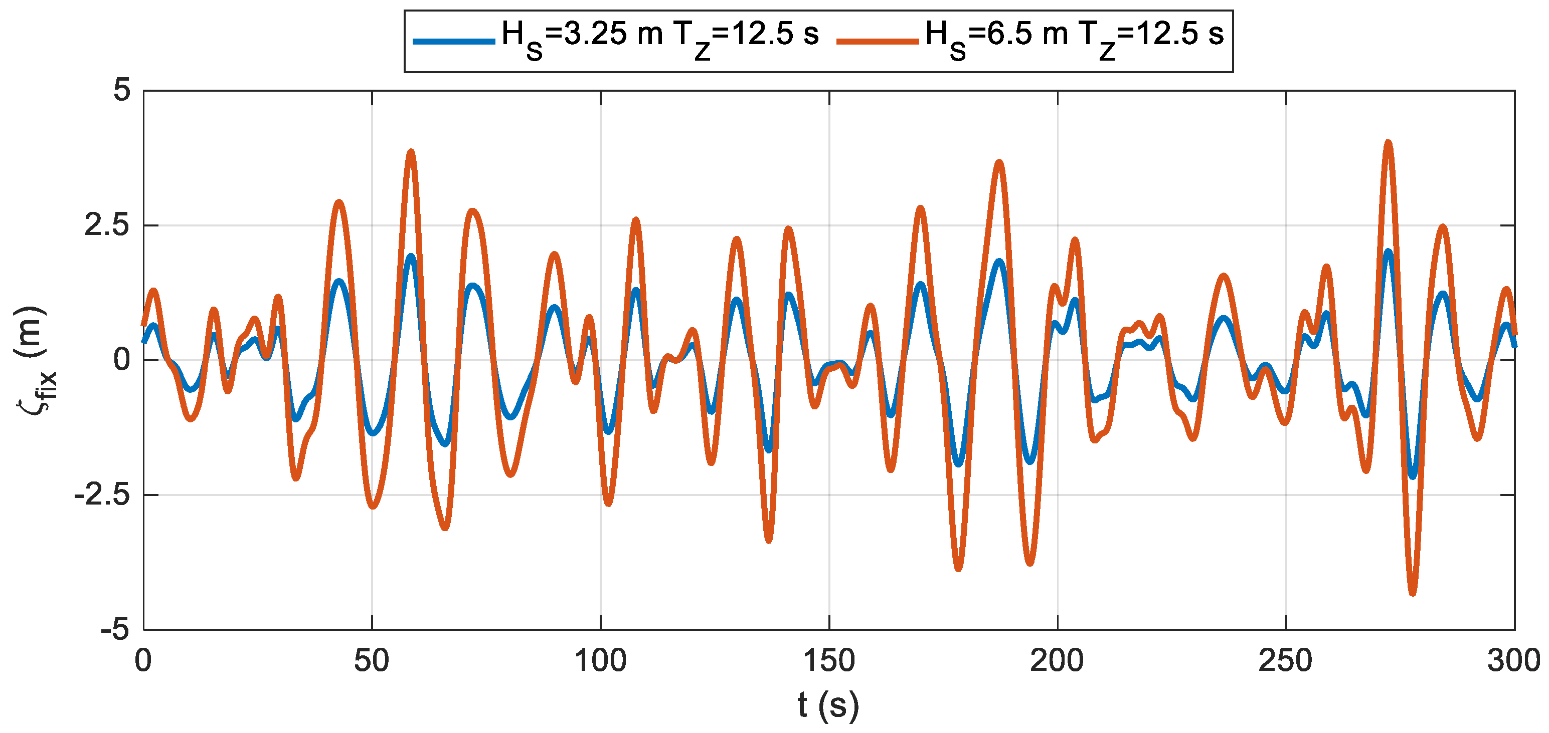
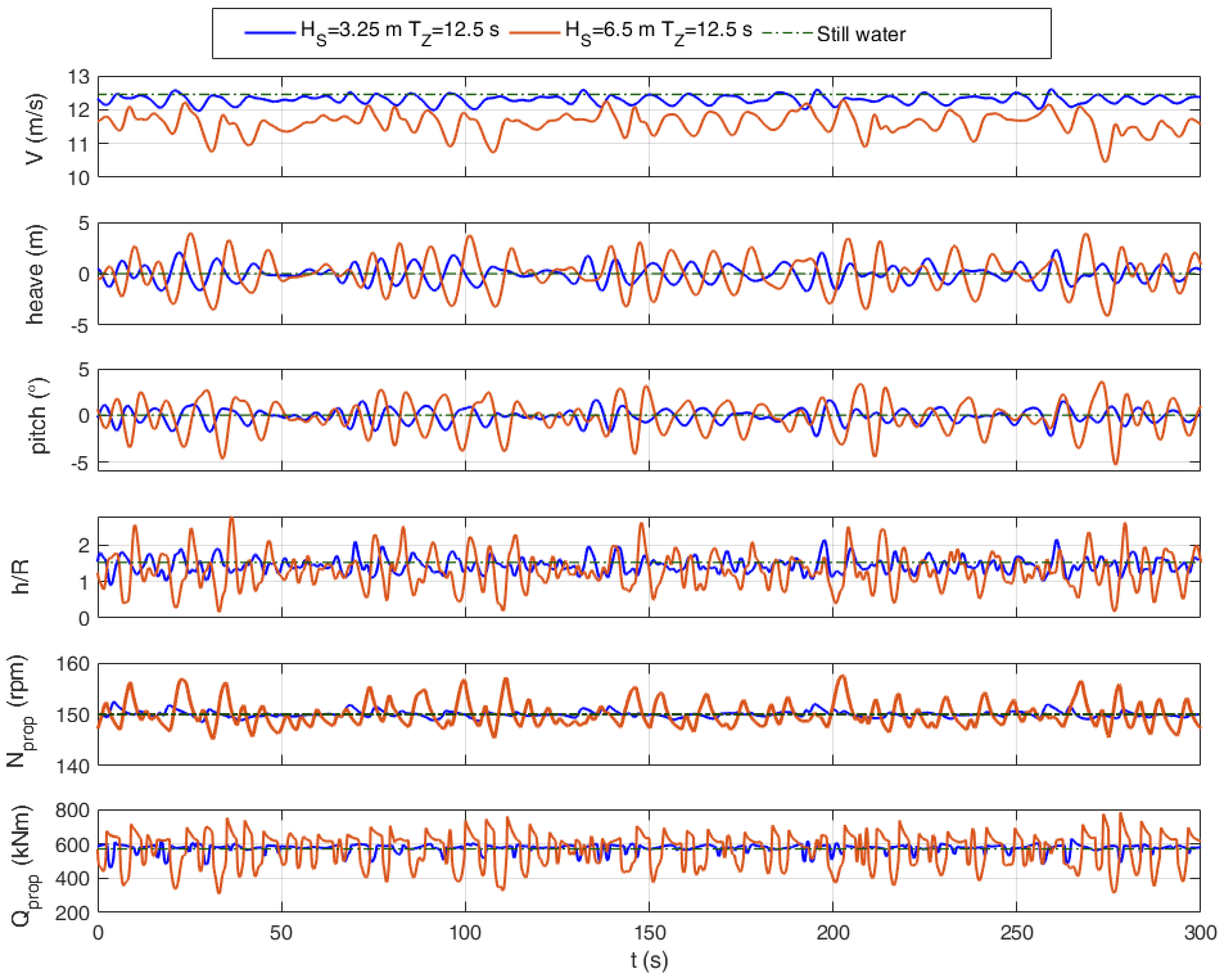
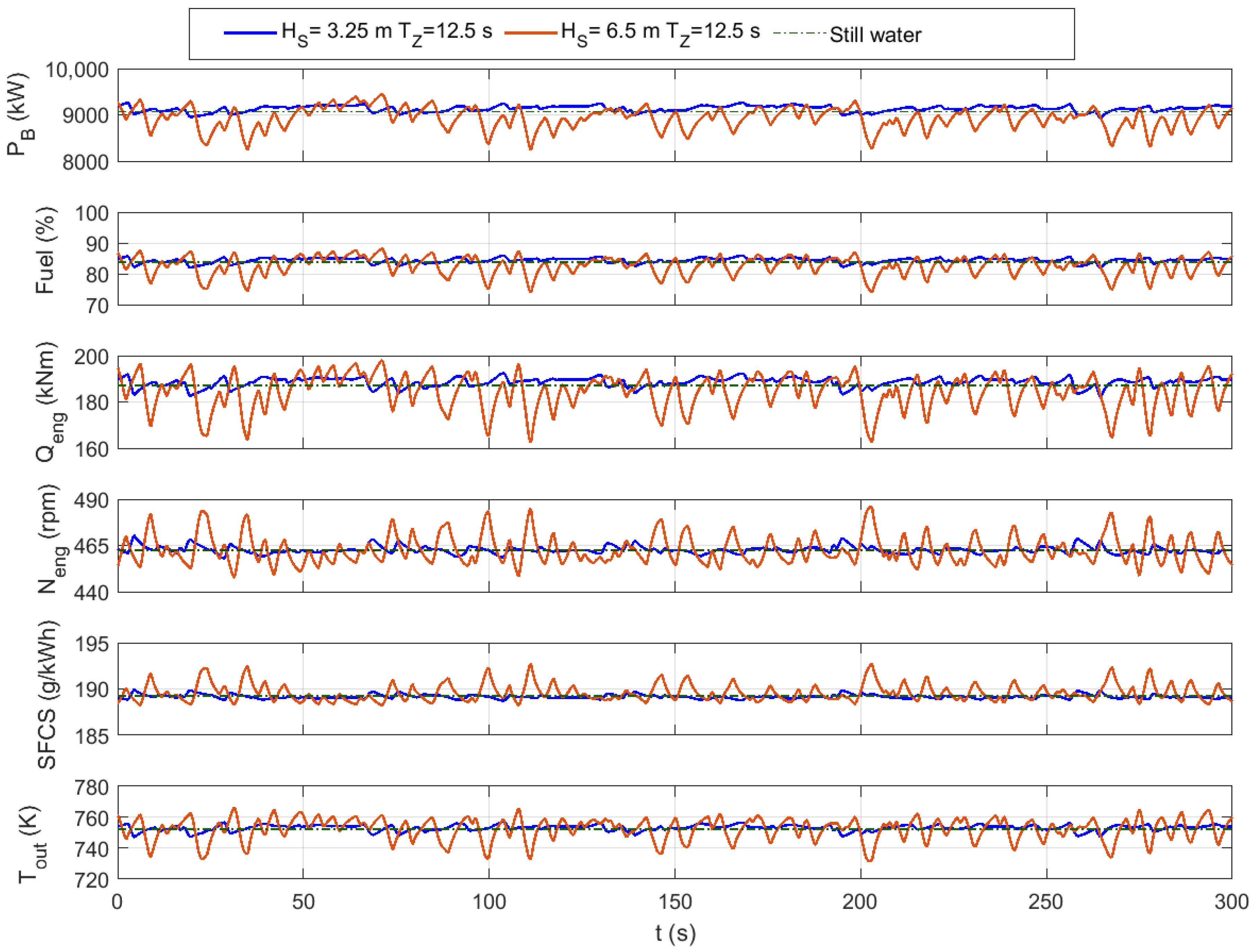
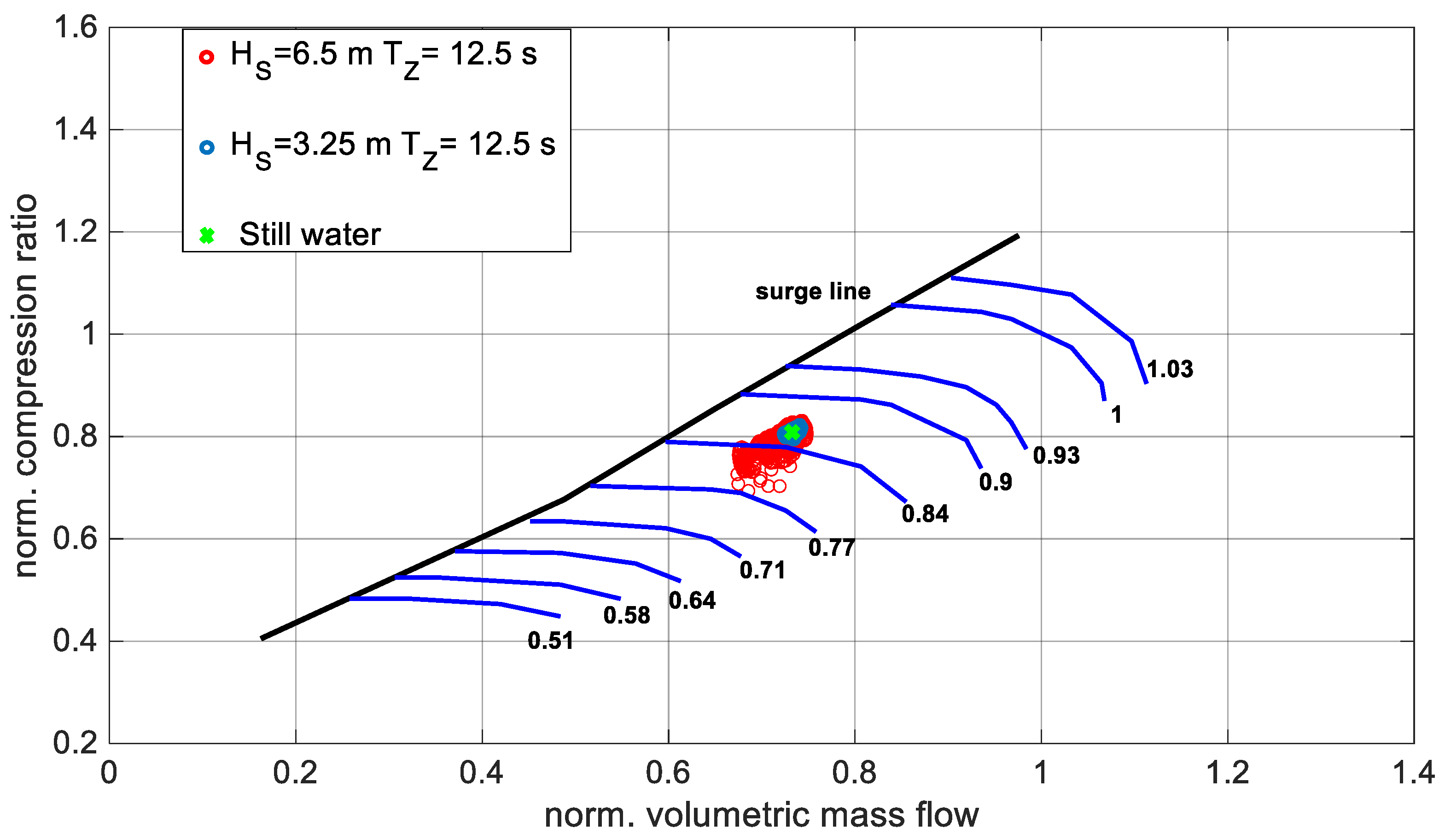
The hull chosen for the case study was a ro-pax ferry named SeatechD, which has been used for previous validations and applications of the method for ship dynamics in waves [49]. Since the hull model was developed mainly for research purposes on ship stability and maneuvering in waves [58], no precise information on propeller and engine at full scale are available. Therefore, at the scope of the case study, the maximum speed was set as 24 knots, (that is reasonable for the hull under investigation compared to other similar vessels) and two Wageningen B-series propellers (for which KT and KQ coefficients are available from [59]) were assumed in a twin-screw configuration.
These design choices allowed the use of two diesel engines of 12 MW each [60], for which the numerical model was developed in [53]. Table 2 provides a summary of the hull, propeller, and engine main data.
The sample irregular sea state for the simulation was obtained from the JONSWAP spectrum, given the significant wave height (Hs) and the zero-crossing period (Tz). The technique described in [49] was used for the generation of the irregular wave train.
The following application focuses on a realization of wave trains having a ratio of 1:2 of HS, i.e., two similar wave profiles were generated, differing only in the HS values that were HS = 6.5 m and HS = 3.25 m, respectively (see Figure 2). This analysis aimed at disclosing the non-linear behavior of the whole propulsion chain interacting with ship dynamics in waves. Moreover, an additional application will be carried out at a reduced speed in order to trigger a parametric roll that leads to non-symmetric loads on each propeller.

3.1. Results

The results of this subsection regard the hull–propeller–engine performances for the ship sailing in the head sea in irregular waves characterized by TZ = 12.5 s, HS = 6.5 m, and TZ = 12.5 s, HS = 3.25 m. For the sake of synthesis, we limited the outcomes of the time history to 300 s.
Figure 3 shows ship dynamics and propeller behavior: green dash-dotted line refers to still water results; solid blue line refers to the sea state characterized by the smaller wave height; solid orange line refers to the wave train with the doubled wave height. It is possible observing that, as expected, ship motions (heave and pitch) exhibited larger amplitude in case of larger wave height, but they were not in phase. This was related to a visible reduction in ship speed (approximately 2 knots for Hs = 6.5 m) that significantly changed the encounter frequency of the hull. Moreover, ship dynamics modified the value of h/R, that is the head of water at the propeller h divided by the propeller radius R. Keeping in mind that h/R = −1 implies a fully emerged propeller; in both cases, the propeller stayed at least partially immersed. While for the case Hs = 3.25 m the propeller was scarcely affected by the wave effects (as observable also from revolutions Nprop and torque Qprop), the larger wave amplitude Hs = 6.5 m induced a significant partial emergence of the propeller with h/R close to zero. This induced irregular profiles of propeller torque and revolution, with a reduction in torque and increase in the revolution when h/R tended to zero.
The propeller load directly influences the engine performances in terms of torque and revolutions, Qeng and Neng, respectively. Indeed, in Figure 4, it is possible to observe how the power profile provided by the engine PB exhibited larger fluctuations for sea state Hs = 6.5 m, together with an increase in the specific fuel consumption SFCS. Figure 4 also shows the temperature Tout of the exhaust gases at the cylinder, in order to point out the capabilities of the model in simulating the thermodynamics of the whole turbocharged diesel engine.
At the same scope, Figure 5 illustrates compressor behavior given the compressor map. For the sea state with Hs = 3.25 m, the working conditions of the compressor remained close to the steady working condition (i.e., referring to still water), while they became scattered in the case of Hs = 6.5 m.

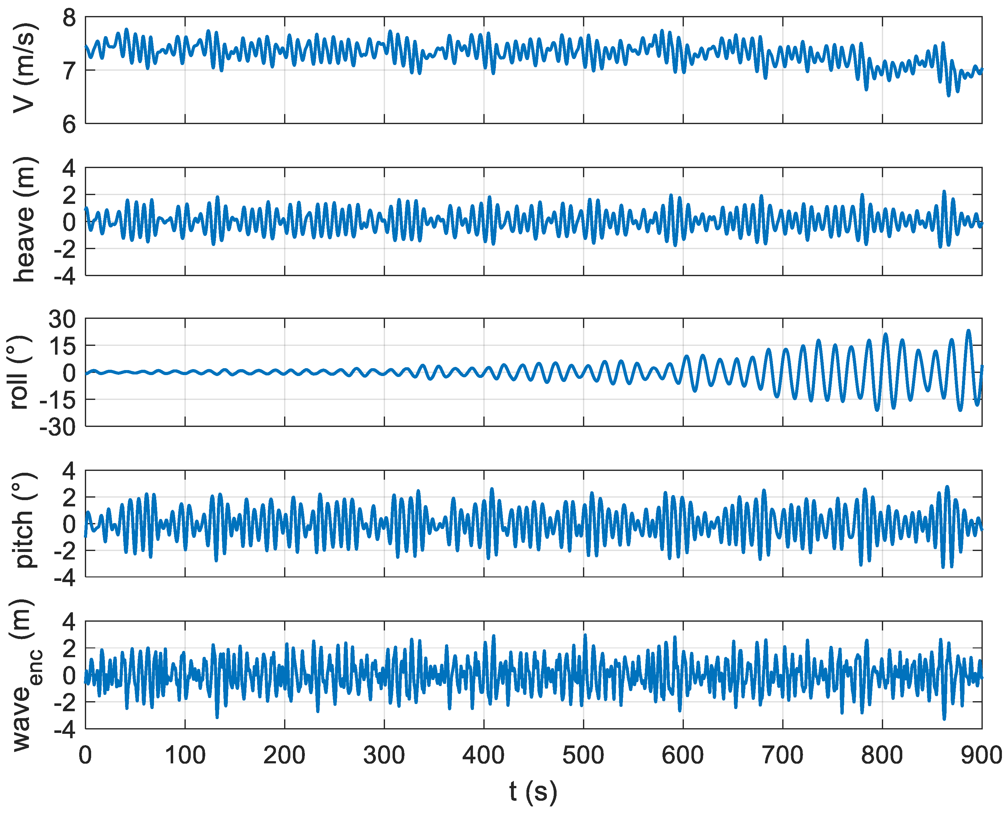
3.2. Results for Parametric Roll Scenario

A ship sailing at maximum speed in a severe–moderate sea state is quite unrealistic, for safety reasons; indeed, it is quite usual that the vessel operates at reduced speed, i.e., at a lower engine load. Actually, this situation could be even more dangerous for ships prone to dynamic instabilities, such as the parametric roll, as in the case of the ro-pax ferry under investigation. The developed code also allowed simulating engine performances in these peculiar circumstances, related to the non-linearities of the immersed hull geometry in waves.
It was found that the ship developed a parametric roll in a head sea in the presence of a sea state characterized by Hs = 4.5 m and Tz = 9.0 s, for a speed of around 15 knots. In such a scenario, the mean wave encounter period was half of the natural roll period of the hull (around 17.5 s), as observable in Figure 6. This figure shows the ship dynamics in waves, focusing on the development of a parametric roll with maximum oscillations of around 20°. This situation induced a non-symmetric behavior of the two propellers and consequently of the two diesel engines. In Figure 7, the starboard propeller and engine outcomes are identified by solid blue lines, while the port propeller and engine outcomes are identified by solid orange lines. It is possible to notice that in presence of a small roll perturbation (i.e., absence of roll), the two propulsion drive chains behaved equally. Once parametric roll develops, the behaviors of starboard-side and port-side propellers and engines were almost 180° out of phase; actually, they were not completely opposite due to the effects of coupling of roll, heave, and pitch on propellers. This results in a large oscillation of engine powers due to the reduction in the propeller torque in correspondence with the propeller emergence, associated with a significant increase in revolutions.

4. Conclusions

This paper concerned the development of a comprehensive numerical model for simulating engine performances accounting for ship dynamics in waves and its effects on propeller loading characteristics. This model represents a first step in the development of a numerical tool to analyze and control the ship propulsion system in unsteady conditions.
From the overall analysis of the numerical outcomes, it is possible to disclose that there was no proportional behavior between the sea state and hull–propeller–engine interaction. In other words, the variation in engine power and consumption did not show a linear behavior with the height of the sea state but depended on multiple interacting factors. Therefore, due to the complexity of phenomena, a simplified approach is not recommended for the assessment of engine performance in waves.
The numerical model presented herein is capable to account for non-linearities that arise from the hull dynamics in waves and interact with the propulsion system. In particular, in this research, the performances of the twin propellers and engines were simulated in event of parametric roll instability in head sea navigation (where usually no roll motion is expected). The main outcomes showed that this critical condition induced a somewhat nonsymmetrical behavior of the thermodynamic engine parameters with large oscillations of torque and revolutions
However, all obtained results can currently provide only a qualitative assessment of hull–propeller–engine behavior, since relevant validations of the complete model are still missing.
It is worth underlining that the main idea behind this research was the possibility to connect hull dynamics with any kind of propulsion system configurations, therefore allowing the modeling and the analysis of the performances of, among other, hybrid propulsion systems. In particular, by combining the prime mover (e.g., a diesel engine equipped with a PTO/PTI shaft generator) to batteries (or fuel cells or even renewable energy sources) for smoothing out the fluctuation of the propeller load, it is possible to optimize the ship propulsion efficiency in sizeable sea waves. The proposed simulator could test a specific control strategy, in order to achieve an averaged load of the diesel engine in severe waves, while the battery system, through the PTO/PTI modes of the shaft generator, will be discharged during short peaks and charged during short dips. Therefore, the engine load can be more constant, by improving fuel efficiency and reducing maintenance costs.

Author Contributions

Conceptualization, M.A. (Maria Acanfora) and M.A. (Marco Altosole); methodology, M.A. (Maria Acanfora), M.A. (Marco Altosole), F.B., L.M. and U.C.; software, M.A. (Maria Acanfora) and U.C.; formal analysis, M.A. (Maria Acanfora), M.A. (Marco Altosole), F.B. and L.M.; investigation, M.A. (Maria Acanfora), M.A. (Marco Altosole), F.B., L.M. and U.C.; resources, M.A. (Maria Acanfora) and U.C.; data curation, M.A. (Maria Acanfora); writing—original draft preparation, M.A. (Maria Acanfora), M.A. (Marco Altosole) and F.B.; writing—review and editing, M.A. (Maria Acanfora), M.A. (Marco Altosole), L.M. and F.B. All authors have read and agreed to the published version of the manuscript.

Funding

This research received no external funding.

Institutional Review Board Statement

Not applicable.

Informed Consent Statement

Not applicable.

Data Availability Statement

Not applicable.

Conflicts of Interest

The authors declare no conflict of interest.

Nomenclature

DpropPropeller diameter
hHead of water on the propeller shaft
HSSignificant wave height
JAdvance coefficient
KQPropeller torque coefficient
KTPropeller thrust coefficient
LShip length
NengEngine revolutions
NpropPropeller revolutions
QengEngine torque
QpropPropeller torque
RPropeller radius
SFCFSpecific fuel consumption
ToutTemperature of the exhaust gases at the cylinder outlet
TpropPropeller thrust
TZZero crossing period
VShip speed
waveencWave profile encountered by the ship
ζfixWave profile in the inertial (fixed) frame
βqvTorque ventilation loss factors
βtvThrust ventilation loss factors
λWavelength
ρDensity of the sea water

References

  1. Okazaki, T.; Nishizaki, C. A study on situation awareness of ship maneuvering simulator training. Int. J. Emerg. Trends Eng. Technol. 2015, 3, 21–30. [Google Scholar]
  2. Altosole, M.; Figari, M.; Martelli, M. Time-Domain Simulation for Marine Propulsion Applications. In Proceedings of the 2012—Summer Computer Simulation Conference, SCSC 2012, Part of SummerSim 2012 Multiconference, Genova, Italy, 8–11 July 2012; Volume 44, pp. 36–43. [Google Scholar]
  3. Campora, U.; Figari, M. Numerical simulation of ship propulsion transients and full-scale validation. Proc. Inst. Mech. Eng. Part M J. Eng. Marit. Environ. 2003, 217, 41–52. [Google Scholar] [CrossRef]
  4. Benvenuto, G.; Carrera, G.; Figari, M.; Campora, U. Interaction Between Ship Propulsion Plant Automation and Simulation. In Proceedings of the 12th International Congress of the International Maritime Association of the Mediterranean, IMAM 2005—Maritime Transportation and Exploitation of Ocean and Coastal Resources, Lisbon, Portugal, 26–30 September 2005; Volume 1, pp. 617–626. [Google Scholar]
  5. Altosole, M.; Figari, M.; Bagnasco, A.; Maffioletti, L. Design and Test of the Propulsion Control of the Aircraft Carrier “Cavour” using Real-Time Hardware in the Loop Simulation. In Proceedings of the SISO European Simulation Interoperability Workshop 2007, EURO SIW 2007, Genova, Italy, 18–20 June 2007; pp. 67–74. [Google Scholar]
  6. Altosole, M.; Benvenuto, G.; Figari, M.; Campora, U. Real-Time Simulation of a COGAG Naval Ship Propulsion System. In Proceedings of the 12th International Congress of the International Maritime Association of the Mediterranean, IMAM 2007—Maritime Industry, Ocean Engineering and Coastal Resources, Varna, Bulgaria, 2–6 September 2008; Volume 1, pp. 331–337. [Google Scholar]
  7. Altosole, M.; Dubbioso, G.; Figari, M.; Viviani, M.; Michetti, S.; Trapani, A.M. Simulation of the Dynamic Behaviour of a Codlag Propulsion Plant. In RINA, Royal Institution of Naval Architects—Warship 2010: Advanced Technologies in Naval Design and Construction, London, UK, 9–10 June 2010; The Royal Institution of Naval Architects: London, UK, 2010; pp. 109–115. [Google Scholar]
  8. Michetti, S.; Ratto, M.; Spadoni, A.; Figari, M.; Altosole, M.; Marcilli, G. Ship Control System Wide Integration and the use of Dynamic Simulation Techniques in the Fremm Project. In Proceedings of the International Conference on Electrical Systems for Aircraft, Railway and Ship Propulsion, ESARS 2010, Bologna, Italy, 19–21 October 2010. [Google Scholar]
  9. Altosole, M.; Figari, M.; Martelli, M.; Orrù, G. Propulsion Control Optimisation for Emergency Manoeuvres of Naval Vessels. In Proceedings of the INEC 2012—11th International Naval Engineering Conference and Exhibition, Edinburgh, UK, 15 May 2012. [Google Scholar]
  10. Altosole, M.; Figari, M.; Ferrero, C.; Giuffra, V.; Piva, L. Propulsion Retrofitting of the Tall Ship Amerigo Vespucci: Automation Design by Simulation. In Proceedings of the 2014 International Symposium on Power Electronics, Electrical Drives, Automation and Motion, SPEEDAM 2014, Ischia, Italy, 18–20 June 2014; pp. 313–318. [Google Scholar]
  11. Altosole, M.; Piastra, F.; Canepa, E. Performance analysis of a motor-sailing propulsion system for control design purposes. Ships Offshore Struct. 2016, 11, 688–699. [Google Scholar] [CrossRef]
  12. Altosole, M.; Campora, U.; Martelli, M.; Figari, M. Performance decay analysis of a marine gas turbine propulsion system. J. Ship Res. 2014, 58, 117–129. [Google Scholar] [CrossRef]
  13. Altosole, M.; Campora, U.; Laviola, M.; Zaccone, R. Deterioration effects on the performance of a steam plant for the waste heat recovery from a marine diesel engine. Ships Offshore Struct. 2019, 14, 867–878. [Google Scholar] [CrossRef]
  14. Zaccone, R.; Altosole, M.; Figari, M.; Campora, U. Diesel Engine and Propulsion Diagnostics of a Mini-Cruise Ship by using Artificial Neural Networks. In Towards Green Marine Technology and Transport—Proceedings of the 16th International Congress of the International Maritime Association of the Mediterranean, IMAM 2015, Pula, Croatia, 21–24 September 2015; CRC Press/Balkema: Boca Raton, FL, USA, 2015; pp. 593–602. [Google Scholar]
  15. Campora, U.; Cravero, C.; Zaccone, R. Marine gas turbine monitoring and diagnostics by simulation and pattern recognition. Int. J. Nav. Archit. Ocean Eng. 2018, 10, 617–628. [Google Scholar] [CrossRef]
  16. Campora, U.; Capelli, M.; Cravero, C.; Zaccone, R. Metamodels of a gas turbine powered marine propulsion system for simulation and diagnostic purposes. J. Nav. Arch. Mar. Eng. 2015, 12, 1–14. [Google Scholar] [CrossRef] [Green Version]
  17. Altosole, M.; Campora, U.; Donnarumma, S.; Zaccone, R. Simulation Techniques for Design and Control of a Waste Heat Recovery System in Marine Natural Gas Propulsion Applications. J. Mar. Sci. Eng. 2019, 7, 397. [Google Scholar] [CrossRef] [Green Version]
  18. Barone, G.; Buonomano, A.; Forzano, C.; Palombo, A. Implementing the dynamic simulation approach for the design and optimization of ships energy systems: Methodology and applicability to modern cruise ships. Renew. Sustain. Energy Rev. 2021, 150, 111488. [Google Scholar] [CrossRef]
  19. Barone, G.; Buonomano, A.; Forzano, C.; Palombo, A.; Vicidomini, M. Sustainable energy design of cruise ships through dynamic simulations: Multi-objective optimization for waste heat recovery. Energy Convers. Manag. 2020, 221, 113166. [Google Scholar] [CrossRef]
  20. Benvenuto, G.; Campora, U.; Carrera, G.; Casoli, P. A Two-Zone Diesel Engine model for the Simulation of Marine Propulsion Plant Transients. In Proceedings of the MARIND 98, Second International Conference on Marine Industry, Varna, Bulgaria, 28 September–2 October 1998. [Google Scholar]
  21. Mrzljak, V.; Medica, V.; Bukovac, O. Quasi-dimensional diesel engine model with direct calculation of cylinder temperature and pressure|Kvazi-dimenzijski model dizelskog motora s direktnim izračunom tlaka i temperature u cilindru. Tech. Gaz. 2017, 24, 681–686. [Google Scholar]
  22. Altosole, M.; Benvenuto, G.; Campora, U.; Laviola, M.; Zaccone, R. Simulation and performance comparison between diesel and natural gas engines for marine applications. Proc. Inst. Mech. Eng. Part M J. Eng. Marit. Environ. 2017, 231, 690–704. [Google Scholar] [CrossRef]
  23. Altosole, M.; Campora, U.; Figari, M.; Laviola, M.; Martelli, M. A diesel engine modelling approach for ship propulsion real-time simulators. J. Mar. Sci. Eng. 2019, 7, 138. [Google Scholar] [CrossRef] [Green Version]
  24. Mrzljak, V.; Medica, V.; Bukovac, O. Volume agglomeration process in quasi-dimensional direct injection diesel engine numerical model. Energy 2016, 115, 658–667. [Google Scholar] [CrossRef]
  25. Mrzljak, V.; Žarković, B.; Poljak, I. Fuel mass flow variation in direct injection diesel engine—Influence on the change of the main engine operating parameters. Pomorstvo 2017, 31, 119–127. [Google Scholar]
  26. Theotokatos, G.; Stoumpos, S.; Lazakis, I.; Livanos, G. Numerical Study of a Marine Dual-Fuel Four-Stroke Engine. In Proceedings of the 3rd International Conference on Maritime Technology and Engineering, MARTECH 2016, Lisbon, Portugal, 4–6 July 2016; Volume 2, pp. 777–786. [Google Scholar]
  27. Tadros, M.; Ventura, M.; Guedes Soares, C. Data Driven In-Cylinder Pressure Diagram Based Optimization Procedure. J. Mar. Sci. Eng. 2020, 8, 294. [Google Scholar] [CrossRef] [Green Version]
  28. Mocerino, L.; Soares, C.G.; Rizzuto, E.; Balsamo, F.; Quaranta, F. Validation of an Emission Model for a Marine Diesel Engine with Data from Sea Operations. J. Mar. Sci. Appl. 2021, 20, 534–545. [Google Scholar] [CrossRef]
  29. Senčić, T.; Mrzljak, V.; Blecich, P.; Bonefačić, I. 2D CFD Simulation of Water Injection Strategies in a Large Marine Engine. J. Mar. Sci. Eng. 2019, 7, 296. [Google Scholar] [CrossRef] [Green Version]
  30. Altosole, M.; Martelli, M.; Vignolo, S. A mathematical model of the propeller pitch change mechanism for the marine propulsion control design. Sustainable Maritime Transportation and Exploitation of Sea Resources. In Proceedings of the 14th International Congress of the International Maritime Association of the Mediterranean, IMAM 2011, Genova, Italy, 13–16 September 2011; Volume 2, pp. 649–656. [Google Scholar]
  31. Altosole, M.; Benvenuto, G.; Figari, M. Performance Prediction of a Planing Craft by Dynamic Numerical Simulation. In Proceedings of the 7th Symposium on High Speed Marine Vehicles, 2005 Conference, HSMV 2005, Napoli, Italy, 21–23 September 2005; Volume 2005, pp. 105–111. [Google Scholar]
  32. Altosole, M.; Benvenuto, G.; Figari, M.; Campora, U. Dimensionless Numerical Approaches for the Performance Prediction of Marine Waterjet Propulsion Units. Int. J. Rotating Mach. 2012, 2012, 321306. [Google Scholar] [CrossRef] [Green Version]
  33. Altosole, M.; Donnarumma, S.; Spagnolo, V.; Vignolo, S. Marine Cycloidal Propulsion Modelling for DP Applications. In Proceedings of the 7th International Conference on Computational Methods in Marine Engineering, MARINE 2017, Rome, Italy, 29–31 May 2017; Volume 2017, pp. 206–219. [Google Scholar]
  34. Tavakoli, S.; Najafi, S.; Amini, E.; Dashtimansh, A. Ship acceleration motion under the action of a propulsion system: A combined empirical method for simulation and optimization. J. Mar. Eng. Technol. 2021, 20, 200–215. [Google Scholar] [CrossRef]
  35. Sutulo, S.; Soares, C.G. Mathematical Models for Simulation of Manoeuvring Performance of Ships. In Marine Technology and Engineering; Taylor & Francis Group: London, UK, 2011; pp. 661–698. [Google Scholar]
  36. Altosole, M.; Boote, D.; Brizzolara, S.; Viviani, M. Integration of numerical modeling and simulation techniques for the analysis of towing operations of cargo ships. Int. Rev. Mech. Eng. 2013, 7, 1236–1245. [Google Scholar]
  37. Ircani, A.; Martelli, M.; Viviani, M.; Altosole, M.; Podenzana-Bonvino, C.; Grassi, D. A simulation approach for planing boats propulsion and manoeuvrability. Trans. R. Inst. Nav. Archit. Part B Int. J. Small Cr. Technol. 2016, 158(Part B1), B-27–B-42. [Google Scholar]
  38. Piaggio, B.; Viviani, M.; Martelli, M.; Figari, M. Z-Drive Escort Tug manoeuvrability model and simulation. Ocean Eng. 2019, 191, 106461. [Google Scholar] [CrossRef]
  39. Martelli, M.; Viviani, M.; Altosole, M.; Figari, M.; Vignolo, S. Numerical modelling of propulsion, control and ship motions in 6 degrees of freedom. Proc. Inst. Mech. Eng. Part M J. Eng. Marit. Environ. 2014, 228, 373–397. [Google Scholar] [CrossRef]
  40. Donnarumma, S.; Martelli, M.; Vignolo, S. Numerical Models for Ship Dynamic Positioning. In Proceedings of the VI International Conference on Computational Methods in Marine, Rome, Italy, 15–17 June 2015; pp. 1078–1088. [Google Scholar]
  41. Spanos, D.; Papanikolaou, A. International Benchmark Study on Numerical Simulation Methods for the Prediction of Parametric Rolling of Ships in Waves. NTUA-SDL Report, Rev. 4. 2009. Available online: http://old.naval.ntua.gr/sdl/sibs/intact/BENCHMARK_REPORT_NTUA-rev.1.0.pdf (accessed on 12 December 2021).
  42. Shigunov, V.; El Moctar, O.; Papanikolaou, A.; Potthoff, R.; Liu, S. International benchmark study on numerical simulation methods for prediction of manoeuvrability of ships in waves. Ocean Eng. 2018, 165, 365–385. [Google Scholar] [CrossRef]
  43. Ghaemi, M.H.; Zeraatgar, H. Analysis of hull, propeller and engine interactions in regular waves by a combination of experiment and simulation. J. Mar. Sci. Technol. 2020, 26, 257–272. [Google Scholar] [CrossRef]
  44. Benvenuto, G.; Campora, U.; Carrera, G.; Figari, M. Simulation of Ship Propulsion Plant Dynamics in Rough Sea. In Proceedings of the 8th International Conference on Marine Engineering Systems (ICMES 2000), New York, NY, USA, 22–23 May 2000. [Google Scholar]
  45. Saettone, S.; Tavakoli, S.; Taskar, B.; Jensen, M.V.; Pedersen, E.; Schramm, J.; Steen, S.; Andersen, P. The importance of the engine-propeller model accuracy on the performance prediction of a marine propulsion system in the presence of waves. Appl. Ocean Res. 2020, 103, 102320. [Google Scholar] [CrossRef]
  46. Tavakoli, S.; Saettone, S.; Steen, S.; Andersen, P.; Schramm, J.; Pedersen, E. Modeling and analysis of performance and emissions of marine lean-burn natural gas engine propulsion in waves. Appl. Energy 2020, 279, 115904. [Google Scholar] [CrossRef]
  47. Matusiak, J. Dynamics of a Rigid Ship; Aalto University Publication Series: Espoo, Finland, 2013. [Google Scholar]
  48. Matusiak, J. On the non-linearities of ship’s restoring and the Froude-Krylov wave load part. Int. J. Nav. Archit. Ocean. Eng. 2010, 3, 151–159. [Google Scholar]
  49. Acanfora, M.; Rizzuto, E. Time domain predictions of inertial loads on a drifting ship in irregular beam waves. Ocean Eng. 2019, 174, 135–147. [Google Scholar] [CrossRef]
  50. Acanfora, M.; Balsamo, F. The Smart Detection of Ship Severe Roll Motions and Decision-Making for Evasive Actions. J. Mar. Sci. Eng. 2020, 8, 415. [Google Scholar] [CrossRef]
  51. Taimuri, G.; Matusiak, J.; Mikkola, T.; Kujala, P.; Hirdaris, S. A 6-DoF maneuvering model for the rapid estimation of hydrodynamic actions in deep and shallow waters. Ocean Eng. 2020, 218, 108103. [Google Scholar] [CrossRef]
  52. Acanfora, M.; Montewka, J.; Hinz, T.; Matusiak, J. Towards realistic estimation of ship excessive motions in heavy weather. A case study of a containership in the Pacific Ocean. Ocean Eng. 2017, 138, 140–150. [Google Scholar] [CrossRef]
  53. Benvenuto, G.; Campora, U.; Laviola, M.; Terlizzi, G. Simulation Model of a Dual-Fuel Four Stroke Engine for Low Emission Ship Propulsion Applications. Int. Rev. Mech. Eng. 2017, 11, 817–824. [Google Scholar] [CrossRef]
  54. Faltinsen, O.M. Sea Loads on Ships and Offshore Structures; Cambridge University Press: Cambridge, UK, 1990; Volume 1. [Google Scholar]
  55. Yu, J.-W.; Lee, C.-M.; Choi, J.-E.; Lee, I. Effect of ship motions on added resistance in regular head waves of KVLCC2. Ocean Eng. 2017, 146, 375–387. [Google Scholar] [CrossRef]
  56. Kim, D.J.; Yun, K.; Park, J.-Y.; Yeo, D.J.; Kim, Y.G. Experimental investigation on turning characteristics of KVLCC2 tanker in regular waves. Ocean Eng. 2019, 175, 197–206. [Google Scholar] [CrossRef]
  57. Smogeli, O.N. Control of Marine Propellers from Normal to Extreme Conditions. Ph.D. Thesis, Faculty of Engineering Science and Technology, Trondheim, Norway, 2006. [Google Scholar]
  58. Matusiak, J.; Stigler, C. Ship Roll Motion in Irregular Waves During a Turning Circle Maneuver. In Proceedings of the 11th International Conference on Stability of Ships and Ocean Vehicles, Athens, Greece, 23–28 September 2012; pp. 291–298. [Google Scholar]
  59. Barnitsas, M.M.; Ray, D.; Kinley, P. Kt, Kq and Efficiency Curves for the Wageningen B-Series Propellers; University of Michigan: Ann Arbor, MI, USA, 1981. [Google Scholar]
  60. MAN. MAN 51/60 DF IMO TIER II/IMO TIER III. In Project Guide—Marine; MAN: Augsburg, Germany, 2015. [Google Scholar]
Figure 1. Revolution response to rpm ramp.
Jmse 10 00036 g001
Figure 2. Time history of the two irregular wave trains (in the inertial reference frame).
Jmse 10 00036 g002
Figure 3. Time history of ship dynamics and propeller behavior in a head sea, for two proportional irregular sea states and still water.
Jmse 10 00036 g003
Figure 4. Time history of diesel engine performances in a head sea, for two proportional irregular sea states and still water.
Jmse 10 00036 g004
Figure 5. Comparison of compressor performances in a head sea, for two proportional irregular sea states and still water. Surge line in black, compression ratio at constant revolutions in blue.
Jmse 10 00036 g005
Figure 6. Time history of the ship dynamics in a head sea, Hs = 4.5 m Tz = 9.0 s: parametric roll development.
Jmse 10 00036 g006
Figure 7. Time history of starboard-side and port-side propellers and engine in a head sea, Hs = 4.5 m Tz = 9.0 s, depending on ship roll motion (black line).
Jmse 10 00036 g007
Table 1. Comparison of experimental and numerical speed reduction in waves for KVLCC2.
λ/LExp (Knots)Sim (Knots)Error (Knots)Err %
0.512.115.33.226%
0.710.915.14.239%
18.69.50.910%
1.210.29.2−1−10%
1.512.611.6−1−8%
Table 2. Principal particulars of SeatechD.
Hull Seatech-D
Length between perpendiculars, L (m)158.00
Breadth, B (m)25.00
Depth, D (m)15.00
Draft forward, TF (m)6.10
Draft aft, TA (m)6.10
Displacement, Δ (tons)13,766
Center of gravity above the keel, KG (m)11.834
Long. coordinate of the center of gravity from aft perpendicular, LCG (m)74.77
Transv. radius of gyration in air, kXX (m)10.06
Long. radius of gyration in air, kYY (m)39.36
Propeller Wageningen B-series
Number of blades Z4
Ae/A00.750
Dprop (m)4.8
P/Drop1.2
Engine
Number of cylinders12
Bore (m)0.51
Stroke (m)0.60
Engine revolution Neng (rpm)514
Engine power PB (MW)12
Publisher’s Note: MDPI stays neutral with regard to jurisdictional claims in published maps and institutional affiliations.

