Review

Review of Recent Offshore Wind Turbine Research and Optimization Methodologies in Their Design

Department of Ocean Engineering, Texas A&M University, College Station, TX 77843, USA
*
Author to whom correspondence should be addressed.
J. Mar. Sci. Eng. 2022, 10(1), 28; https://doi.org/10.3390/jmse10010028
Submission received: 14 December 2021 / Revised: 22 December 2021 / Accepted: 23 December 2021 / Published: 28 December 2021

Abstract

:
As international efforts to address climate change grow, an increasing number of countries and companies have put forward a clear “net zero” goal through accelerated renewable-energy development. As a renewable energy source, offshore wind energy has received particular attention from many countries and is a highly active research area. However, the design of offshore wind turbine structures faces challenges due to the large and complex design parameter space as well as different operational requirements and environmental conditions. Advanced optimization technology must be employed to address these challenges. Using an efficient optimization algorithm, it is possible to obtain optimized parameters for offshore wind turbine structures, balancing energy generation performance and the life of the floating wind turbine. This paper presents a review of the types and fundamental principles of several critical optimization technologies along with their application in the design process, with a focus on offshore wind turbine structures. It concludes with a discussion of the future prospects of optimization technology in offshore wind research.

1. Introduction

With the rapid growth of global energy, climate change and ecological and environmental issues are increasingly concerning. In this regard, the use of clean and renewable energy is increasingly underscored. As a clean renewable energy source, offshore wind energy is receiving particular attention from many countries, and numerous relevant studies and projects have been conducted.
Offshore winds are generally much stronger and steadier compared to those inland. Furthermore, offshore wind has less turbulence intensity and a more stable dominant direction, which is beneficial regarding wind-induced turbine fatigue. In addition, an offshore wind turbine is less restrained against noise, visual obstruction, residents’ opposition, and space restrictions. In most countries, the majority of populations live near coastal regions, which makes offshore wind turbines more competitive. Since offshore wind energy does not cause any air pollution and produces no harmful waste, it is expected to play an increasingly important role in the future energy market.
According to the global wind report [1], in 2021, the global wind power capacity reached 733 GW, and the total installed capacity of wind power in China reached 282 GW. Countries with installed wind power capacity exceeding 10 GW include the United States of America (118 GW), Germany (62 GW), India (39 GW), Spain (27 GW), the UK (24 GW), France (17 GW), Brazil (17 GW), Canada (14 GW), and Italy (11 GW). In recent years, the further development of offshore wind power technology has been attempted, with significant progress. Europe plays a leading role, with 90% of wind turbine manufacturers and 75% of installed wind power capacity concentrated there.
In shallow water, offshore wind turbines are fixed using pillar (monopile) or jacket structures. In the case of a fixed pillar structure, the pillar, which is generally composed of steel, is driven deep below the seabed through hammering. Most existing shallow offshore wind farms use this kind of foundation. This structure is restricted by geological conditions and water depth. Many such bottom-fixed offshore wind turbines can be found off the coast of Denmark [2].
In deep water, it is hard for bottom-fixed foundations to meet the design requirements in view of the lowest natural frequencies being closer to dominant wave frequencies. Therefore, in the case of water depths greater than 50 m, floating foundations are recommended. For large water depths and a soft seabed, floating wind turbines (FWTs) are generally more cost-effective, as the overall cost only marginally increases with the additional length of mooring lines. Because they are installed far from the shore, they are less restricted by size, noise, scenery, and other regulations. FWTs can be used in water as deep as 700 m and obviate the need for tall towers and specialized materials designed for deep water [2].
Henderson et al. [3] discussed the advantages of utilizing floating foundations and outlined the technical challenges for different types. They also provided a detailed overview of the potential new markets for FWT technology. Wang et al. [4] presented a literature survey of the research and development of FWTs. Offshore floating wind turbines use various mooring systems anchored at the seabed. In 1972, Heronemus [5] proposed the floating offshore wind turbine (FOWT) concept. In the 1990s, researchers from various countries began to work on the development of several different FOWT concepts. Among them, the spar-buoy (spar), tension leg platforms (TLPs), and bargelike or semisubmersible platforms (barge) are the most popular [6]. The spar wind turbine is a deep-draft vertical cylinder similar to existing oil and gas spar platforms, with a tall tower and a rotor-nacelle assembly (RNA) at its top. The floating foundation (consisting of a steel and/or concrete cylinder filled with water or gravel ballasts to keep the center of gravity below the center of buoyancy) ensures that the wind turbine floats in the sea and stays upright during wet towing through a sizeable righting moment arm and high inertial resistance to pitch and roll motions [4]. The draft of the floating foundation is usually larger than or at least equal to the hub height above sea level for maintaining pitch–roll stability and minimizing heave motion. Tension leg platforms (TLPs) are extensively used in the offshore oil and gas industry and are employed as FOWT [7]. The TLP wind turbine has extremely small heave, pitch and roll motions compared to other floating foundations, and could lead to significantly reduced fabrication costs due to the reduced steel weight compared to that of fixed offshore wind turbines. The barge type uses a wide and shallow-draft barge as its floating foundation. In the barge concept, the required pitch–roll restoring moment for stabilization is achieved from a large water-plane area [7]. However, the greatest disadvantage of this type is large-wave-induced motions, unless they are effectively controlled. In this regard, semisubmersible-type floating foundations are preferred. The greatest advantage of the shallow-draft foundation, like the barge or semisubmersible, is that quay-side assembly and wet towing are possible, which avoids dangerous offshore assembly and installation.
Due to the growing interest in offshore wind energy, offshore wind turbine design optimization research has increased over the past few decades. Figure 1 demonstrates the number of journal papers that discussed the design and optimization of offshore wind turbines. There has been rapid growth in the number of papers, especially in the last 10–15 years.
The present paper begins with an overview of the state-of-the-art in different offshore wind turbine concepts and their differences in design, cost, and expected performance. The general design and optimization approaches for offshore wind turbines are then reviewed. This includes static, frequency-domain, and time-domain analyses. Optimization criteria involved in these optimization approaches are also included. Then, several widely used optimization methods and their potential applications in offshore wind turbine design optimization are described in Section 4. Lastly, a brief summary of the main findings and future research directions of this work are provided in Section 5.

2. Type of Offshore Wind Turbine

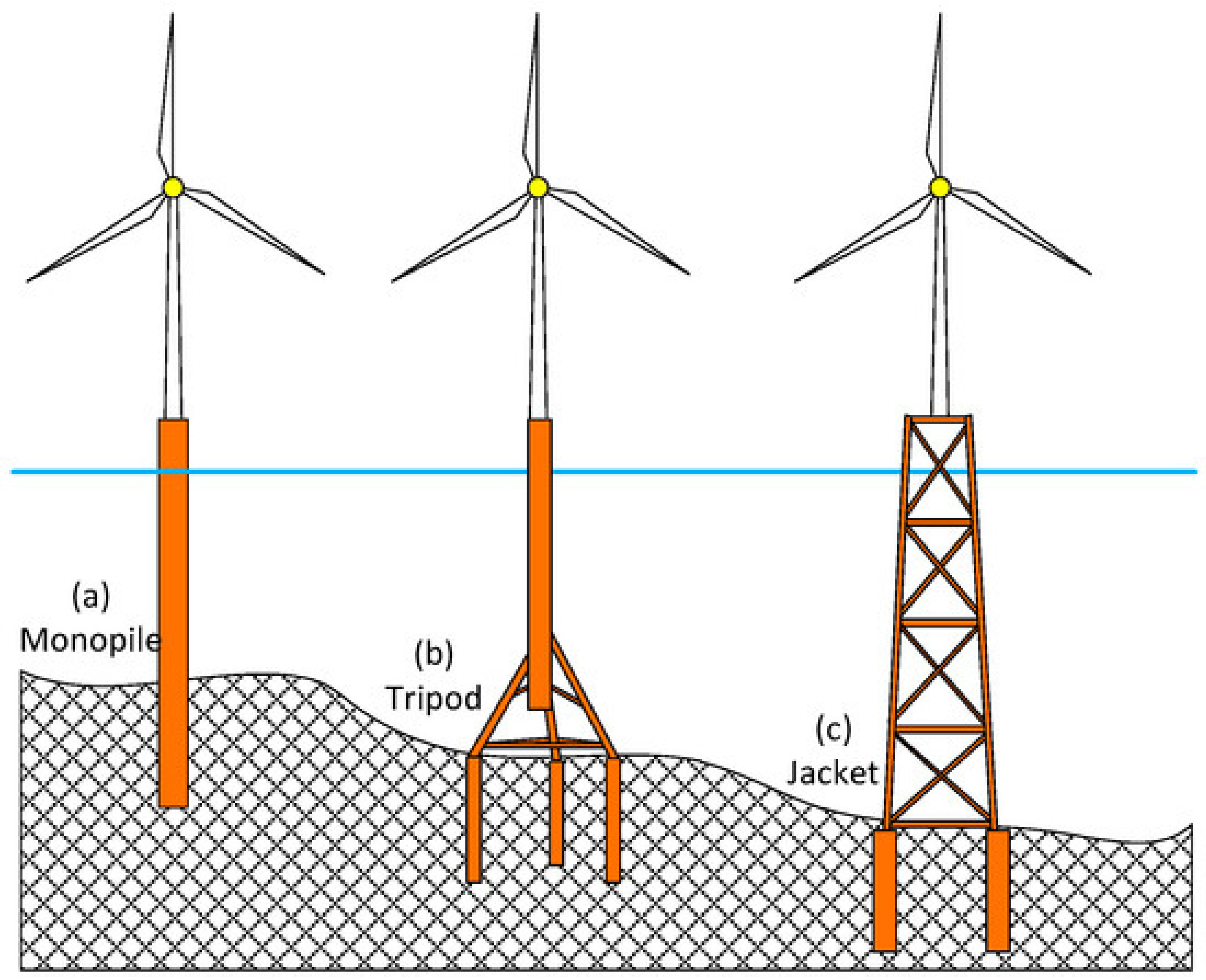
2.1. Fixed Substructure

2.1.1. Monopile Substructure

In the last few decades, the most popular and widely adopted modern offshore wind foundation system has been the monopile foundation. Nearly 81% of all existing European offshore wind turbines consisted of a monopole foundation by the end of 2016 [8,9], such as Horns Rev 1–3, the Anholt projects in Denmark, the London Array project UK, and the Dantysk project in Germany. The monopile is generally used in areas with relatively shallow water depth (<40 m). The typical diameter of the steel tubular section is 3–6 m, length of 20–50 m, and up to 1000 tons [10,11]. Depending on seabed characteristics, total applied load, and design criteria, 40–50% of the steel tubular section is inserted into the seabed to provide resistance by the surrounding soil along the embedded length. A monopile is generally manufactured onshore, then transported to the operation location for installation by pile driving or drilling. Because no seabed preparation is necessary, the installation can generally be achieved within 24 h [12,13,14].

2.1.2. Tripod Substructure

For larger turbines and deeper water up to 50 m, a tripod, an extension of the monopile is generally used [15]. Tripods consist of three-legged tripod bases connected to a large-diameter central steel tubular section and the seabed. These three piles are embedded 10–20 m into the seabed to provide significant resistance for better stability performance and stiffness of the entire offshore wind turbine substructure [10,16], depending on the special equipment required for driving or drilling. The typical installation of a tripod offshore wind turbine up to 700 tons generally takes 2–3 days [12,17]. Similar to the monopile, the installation of a tripod foundation does not require seabed preparation. However, due to heavier foundations tripod construction and maintenance costs can be higher than those of other base types. In addition, erosion protection is required for the tripod in locations where bottom currents are significant or where sediment is easily eroded. Examples of tripod-foundation wind farms are AlphaVentus, Trianel Windpark Borkum I, and Global Tech I.

2.1.3. Jacket Substructure

For deeper water oil and gas platforms up to 60 m, a jacket or braced frame substructure is generally used [18,19]. The jacket structure is composed of a small-diameter lattice truss. This lattice truss structure is connected with three or four tubular legs that are driven into the seabed. The jacket substructure can be installed down to depths of 10–60 m, and some can be extended to 80 m [15]. The general installation of the jacket substructure can be completed in three days. The main advantage of a jacket substructure includes that it is particularly suitable for severe offshore conditions, as truss components offer higher resistance to prevailing ocean waves and current flow in comparison with monopile or tripod structures, and can adjust their application range with geometrical variations without altering the stiffness of the whole structure [20]. The main disadvantage of the jacket substructure is higher installation and construction cost, and it is always used as a transitional water substructure [10,21]. Due to erosion, the jacket structure’s joints generally require long maintenance downtime periods in order to sustain structural integrity. Some deeper-water wind farms use jacket foundations, for example Beatrice and Thornton Bank Phases II and III.
We demonstrate the advantages and disadvantages of the three most common substructure types used for fixed offshore wind turbines in Table 1. We also demonstrate the main types of fixed offshore wind turbine substructure in Figure 2.

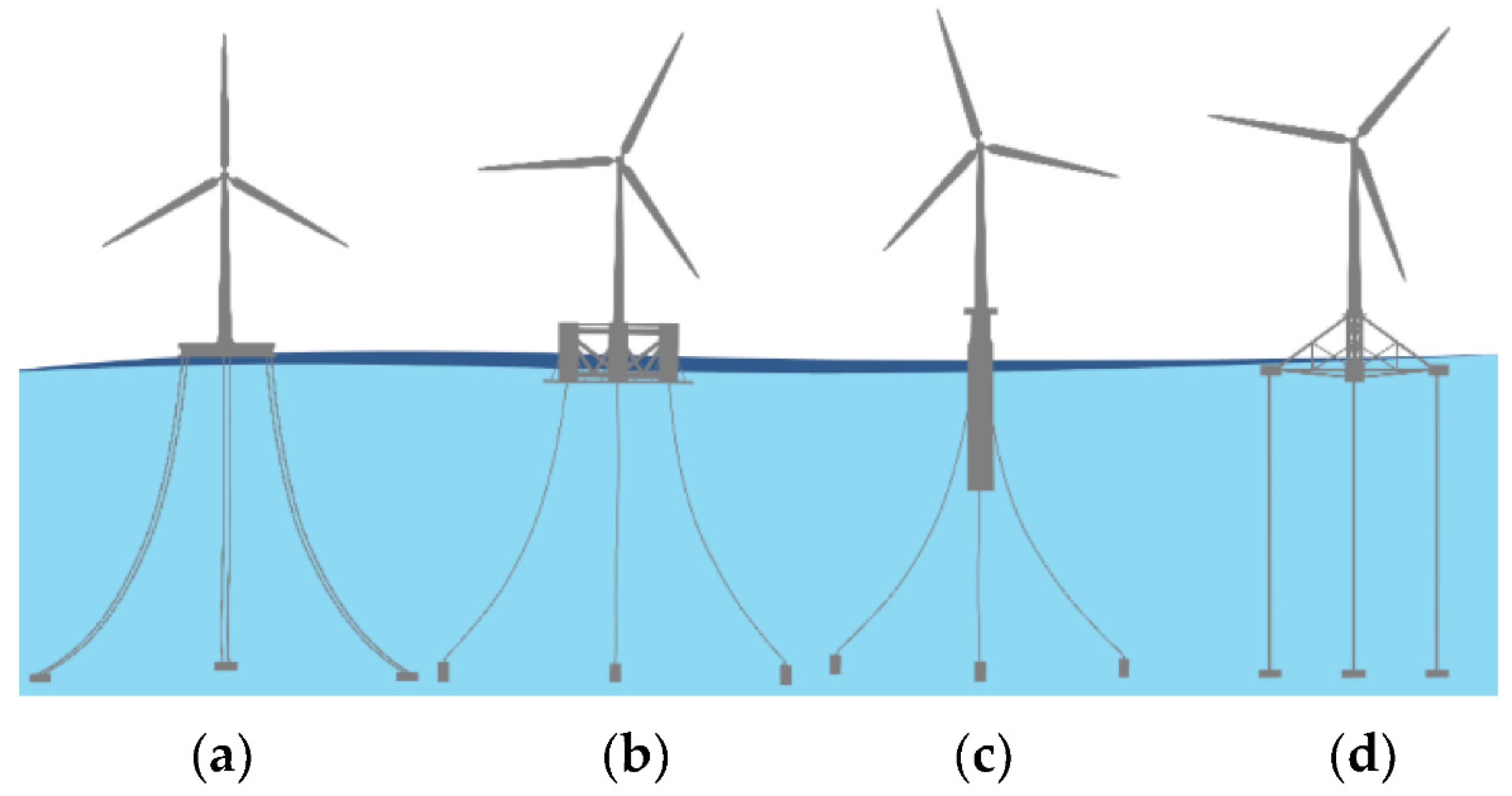
2.2. Floating Substructure

In recent years, floating offshore wind technology has rapidly generated several different types of wind turbine. The four main types, as illustrated in Figure 3, are:
  • Spar–buoy
  • Semisubmersible
  • Tension leg platform (TLP)
  • Barge

2.2.1. Spar–Buoy Substructure

The spar-type platform is a deep-draft vertical cylinder, which provides buoyancy. Roll/pitch stability is maintained by placing the center of gravity sufficiently below the center of buoyancy. For station keeping, a catenary or semi-taut spread mooring system of chains, steel cables, and/or synthetic fiber ropes can be used. The hull can float horizontally and be wet-towed, then the bottom part can be water-ballasted to a vertical position. Due to the deep draft, RNA assembly and a hull at the quayside are impossible except in the case of deep Norwegian fjords. The floating spar–buoy concept is the most technically proven concept among floating wind turbines. This technology was adopted in the first full-scale FOWT prototype Hywind, which had been deployed in Norway by Statoil in 2009 [24]. Hywind is the first FOWT project in which the 6 MW-scale wind turbine was installed.
The first commercial floating wind farm consisting of five 6 MW spar-type FOWTs was commissioned by Statoil off the coast of Scotland in 2020. A concept of spar-type FOWT was well-defined and studied by the IEA Wind Task 23 subtask 2 OC3 project [25] to support an NREL 5 MW reference wind turbine on the basis of the Hywind prototype [24]. The scale model tests of OC3-Hywind were carried out in the MARIN wave tank in The Netherlands and the Ocean Engineering Wide Tank of the University of Ulsan (UOU), Korea [26]. Another relatively recent model is the SWAY-type offshore wind turbine. SWAY is moored by a single vertical tendon held at the base by a swivel connection that allows for the wind turbine to revolve as the wind changes direction [2].
Many numerical and experimental studies have been carried out to analyze the performance of the spar-type offshore wind turbines. This research is generically multidisciplinary, involving aerodynamics, hydrodynamics, multi-structure dynamics (elastic), and automated control [27,28]. Numerical methods such as blade element momentum (BEM) theory, generalized dynamic wake (GDW) theory, and the computational fluid dynamics (CFD) method are generally used for the simulation of FOWT aerodynamics [29,30,31]. In addition, coupled dynamics analysis and simulation tools were developed for the FOWT [32]. Among this numerical simulation software, the FAST platform, developed by NREL, is the most widely used and well-known for the numerical simulation of FOWT [33]. In addition, experimental studies have been conducted and developed to analyze the performance of the spar-type FOWT. In an effort to validate FAST and other offshore wind energy modeling tools, the DeepCwind project tested three prototype floating wind turbines at 1/50th scale in a wave basin: a semisubmersible, a tension-leg platform, and a spar buoy [34]. The Froude number can be used for the wave-induced dynamics between model and prototype, whereas aerodynamic similarity was not met since it is governed by the Reynolds scale. Thus, in many cases, a disk of similar drag force was applied to simulate the wind rotor. Another 1:47 Froude scaled model test of the Hywind spar-type FOWT was conducted under various sea states at the Ocean Basin Laboratory at Martinek [28,35]. A 1:50 scale model of the OC3 spar-type FOWT was produced at the State Key Laboratory of Ocean Engineering at Shanghai Jiao Tong University [36]. Another 1:40 model of OC3-Hywind spar was established in the DHI Offshore Wave Basin in Hørsholm (Denmark). Experimental results and numerical analysis of the FAST code were compared [37]. A numerical study was also developed for the coupled dynamics analysis of the Hywind spar design with a 5 MW turbine in the time domain, including aeroloading, blade–rotor dynamics and control, tower elastic responses, mooring dynamics, and platform motions [38].

2.2.2. Semisubmersible Substructure

As one of the most feasible floating platforms supporting offshore wind turbines, the semisubmersible is rapidly being developed, with the offshore wind industry moving to deep waters (ranging 50–300 m) [39]. Semisubmersibles have relatively shallow drafts compared to spars; thus, both quayside assembly and wet tow are possible, which is one of the greatest advantages of this concept.
MARIN, DUT, TNO, and MSC developed a joint project called Drijfwind in 2002 [40]. A semisubmersible FOWT with a three-legged floating foundation, the Dutch tri-floater, was developed. The project’s main objective was to improve the vertical motion response of the FOWT while reducing the overall construction volume. The model used three hollow columns to provide the necessary buoyance. Each of the columns had a diameter of 8 m and was composed of two layers of shells.
Collu [41,42] further modified and improved the design of the support structure of the Dutch tri-floater. Each column of the foundation was divided into three compartments using two horizon bulkheads. T-/H-section and radius-ring stiffeners were employed to increase the foundation’s integrity, and global/local stiffness.
Another well-known semisub-type FOWT is WindFloat designed by Roddier et al. [24]. Similar to the configuration proposed in the Dutch trifloater, the WindFloat is also based on a three-column foundation. For this design, the wind turbine was installed at one column of the WindFloat, while its vertical position is maintained by ballasting the other columns, i.e., each column of the floating structure is equipped with a permanent water ballast system at the bottom to lower the draft of the structure to the target. In addition, an active water ballast system is used above the permanent water ballast to move the waters between the columns. Because of the active system, the floating structure can easily adjust the weight of each column to keep the wind turbine vertical when the wind speed or direction changes.
A ring-shaped floating foundation is another type of supporting structure used for semisubmersible offshore wind turbines. It features an additional damping pool system, essentially a moon pool constructed inside a ring [43]. The pool is used to act as a damper to reduce the motion of the entire floater.
In 2011, the Fukushima project deployed an FOWT offshore of Fukushima, Japan. In the first phase of the Fukushima project, a 2 MW wind turbine was installed on a compact semisubmersible foundation [44]. The stability of the structure was increased using braces connecting columns and eight catenary mooring line system. In the second phase, a 7 MW wind turbine was installed on a semisubmersible with its pontoons directly connected to columns without braces. The validity and feasibility of such a braceless semisubmersible were investigated by several researchers [45,46,47]. Coupled dynamics studies of semisubmersible FOWTs are important to their design. For example, a recent study conducted a numerical simulation and analysis of the performance changes in an FOWT with a broken mooring line using the OC4 DeepCwind semisubmersible as a reference [48]. A similar study compared the global performance of the OC4 and WindFloat semisubmersible FOWT hulls for the same environmental and control conditions when adopting the same 5 MW wind turbine and catenary mooring system by using the turbine-floater-mooring fully coupled simulation program [49]. Recently, a larger scale semisubmersible floating foundation hosting multiple wind turbines on it was suggested, and a corresponding coupled dynamic analysis tool was developed [50,51,52].

2.2.3. Tension Leg Platform (TLP) Substructure

Tension leg platforms (TLPs) are famous structures in the oil and gas industry and are widely accepted as an FOWT substructure. The TLP wind turbine has the advantage of extremely small heave, pitch, and roll motions compared to those of other floating foundations. It could also significantly lower the manufacturing cost in deep waters compared to fixed platforms.
A TLP wind turbine was installed off the coast of Puglia, southern Italy, by Blue H Technologies. This large-scale prototype was used to test the assembly, transportation, and installation of the TLP-type wind energy converter, and serves as a metering platform with sensors to measure site-specific data. The turbine can generate 80 kW and uses a two-bladed rotor. It was deployed in a water depth of 108 m. Zhao et al. [53] developed a new multicolumn TLP foundation (Windstar TLP) for the NREL offshore 5 MW reference turbine using the same site-specific environmental conditions as those of the OC3-Hywind (NREL). In a study carried out by Bachynski and Moan [54], five different parametric single-column TLPWTs were designed and analyzed under four different wind–wave conditions by using the Simo, Reflex, and Aerodyn numerical tools for coupled analysis to estimate the platform motions and structural loads on turbine components and tendons. Nihei and Fujioka [55] presented the tank test results for a 1:100 scale TLP-type FOWT incorporating three rotating blades. Tests were carried out in both waves and winds. Test results showed that the blade–wind interaction had a beneficial effect of reducing the floater pitch motion and decreasing mooring line vibrations. For the TLP foundation, the dynamic coupling effects between hull or tendon and turbine can be important (e.g., significant shift of the original TLP motion natural frequencies due to the elastic behavior of the tower), and thus need to be modeled as a combined dynamic system. Recently, fully coupled dynamic analysis of a TLP offshore wind turbine in the time domain including blade-rotor dynamics and control, mooring dynamics, and platform motions was conducted, analyzing the coupling effects with rotors on the fatigue life of the FOWT [56].

2.2.4. Barge Substructure

The barge-type FOWT consists of a single or a group of wind turbines on a large shallow-draft barge structure. The stability of the barge type is achieved by a large waterplane area. Similar to the semisubmersible type, quayside assembly and wet tow are possible. The main advantage of the barge-type foundation is simple manufacturing. The main disadvantage of the barge-type wind turbine is its sensitivity to the roll and pitch motions in waves, and it is therefore mainly used in calm seas, e.g., inside a harbor. Only a few barge-type FOWT systems exist, for example the ITI Energy Barge [57]. Floatgen by the French Ideol is unique, with a concrete ring-shaped support structure utilizing a moon pool (sometimes called a damping pool) employed to reduce wave-induced motions [39,58].
In the following, we tabulate the advantages and disadvantages of the four types of floating support in Table 2.

3. Design and Optimization Approaches for Offshore Wind Turbine

In the present review, we divided optimization methods into static, frequency-domain, and time-domain approaches.

3.1. Optimization Based on Static Analysis

Static approaches to structural optimization in wind-energy technology are based on statical structural representations, often using detailed finite-element models. Typical static analysis usually focuses on minimizing the weight of the offshore structure by varying its geometry, e.g., the diameter and thickness of the structure. Other common optimization aspects in static analysis include maximizing the stiffness and preventing the buckling of the offshore wind turbine. Uys et al. [59] showed the optimization of a 1 MW turbine based on three tubular sections with a height of 15 m each. Production costs were minimized, and buckling was taken as a constraint. The design variables were the mean wall thickness of each 15 m segment and a certain number of ring stiffeners to prevent buckling. This method is widely used for onshore wind turbines; for example, using data for a commercial 1.0 MW Acciona turbine and its tower, Chantharasenawong et al. [60] achieved a reduction of more than 20% in tower weight by increasing diameters and reducing section thicknesses, thereby reducing the capacity factor for buckling failure (within allowable limits). Gencturk et al. [61] carried out a similar study to optimize a 100 kW wind turbine design. By tuning the parameters of the transmission line of the lattice tower, the study reduced the weight of the wind turbine by 20%. For offshore wind turbines, static analysis was also applied for design optimizations. In the optimization study of a 5 MW offshore wind turbine by Long et al. [62], the optimal bottom leg distance of the offshore wind turbine’s lattice tower was obtained by performing static analysis and buckling checks. Damiani and Song [63] proposed a jacket sizing tool for systems engineering based on optimization, which allows for the determination of basic topology and dimensions. The objective function quantifies the degree to which the structure succeeds in fulfilling these objectives by a single numerical value (e.g., the total weight of the structure). This value depends in a fixed and predetermined way on the geometric parameters that describe the structure.

3.2. Optimization Based on Frequency-Domain Analysis

Frequency-domain analysis generally refers to the analysis of structural performance in terms of frequency rather than time, which is used in time-domain analysis. It has the advantage of lower computational cost over time-domain analysis. For the design optimization of offshore wind turbines, based on a coupled parametric finite-element analysis (FEA) and genetic algorithm (GA), the study by Gentils et al. [64] minimized the mass of the support structure under multicriteria constraints for a 5 MW offshore wind turbine on an OC3 monopile. The optimization constraints in this study were selected to be vibration, stress, deformation, buckling, fatigue, and design variables. By design optimization, the study showed a 20% reduction in the global mass of the support structure. They concluded that fatigue and natural frequency appeared to be the main design drivers, which agreed with the recommendation from the design standards. Using a combination of static and frequency domain analysis, a design procedure was proposed by Laszlo et al. [65] for the design of offshore wind turbine monopole foundations. The study presented a simplified way of designing monopiles on the basis of necessary data (i.e., the least amount of data), namely site characteristics (wind speed at reference height, wind turbulence intensity, water depth, wave height, wave period), turbine characteristics (rated power, rated wind speed, rotor diameter, cut-in and cut-out speed, mass of the rotor nacelle assembly), and ground profile (soil stiffness variation with depth, soil stiffness at one diameter depth). Design criteria included the ultimate limit state (ULS), target natural frequency, fatigue limit state (FLS), robustness, and ease of installation. Thiry et al. [66] developed a methodology to optimize monopile steel structures (5 MW turbine) with a genetic algorithm. The objective was to minimize the weight of the support structure, while constraints were implemented utilizing penalties in the fitness function. Constraints were taken for both FLS and ULS. FLS was calculated on the basis of structure-independent damage from wind and structure-dependent damage from waves (calculated in the frequency domain by linearly combining the PSDs of the environment and the support structure). ULS was calculated through the wind load on the rotor, the pressure on the structure, and a wave load described by Hw = 10 m and Tw = 14 s. Soil was not considered, as the structure was clamped above the mudline. This study showed a weight reduction of 21%. Van der Tempel [67], and Ziegler et al. [68] proposed another method for calculation of the fatigue life of offshore wind turbines using frequency domain analysis combined with Dirlik’s method [69] to obtain Damage Equivalent Loads. Similarly, Long and Moe [62] applied a frequency-domain fatigue estimation method to determine fatigue loads for offshore wind turbine jacket substructures. Brommundt et al. [70] proposed a spectral method to optimize the mooring system of a floating structure, while a spectral model was also used to predict structural responses of a semisubmersible substructure. Similar works were presented by Michailides and Angelides [71], and Hall et al. [72] proposing a multi-objective formulation and a genetic algorithm to design floating structures and topology.

3.3. Optimization Based on Time-Domain Analysis

Time-domain approaches offer the possibility of carrying out very detailed design assessment which is close to the requirements of design standards and structural code checks. Due to its high computational cost, the time-domain optimization of wind turbines has only recently emerged. It was first used to optimize the design of onshore wind turbines. Yoshida [73] optimized the dimensions of an onshore steel tower 2 MW turbine based on a genetic algorithm and a time-domain simulation tool for structural code checks. An optimization framework based on FAST, capable of performing the design optimization of onshore wind turbines, was presented by Gutierrez et al. [74]. For offshore wind turbines, Ashuri [75] conducted scaling to predict the design of huge offshore wind turbines with an optimization tool. Haghi et al. [76] designed a monopile for a 3.6 MW offshore wind turbine using a similar simulation-based optimization method. In that study, using optimization design, the weight of the support structure was reduced by nearly 12% compared to the initial design. With a time-domain simulation-based optimization tool, Zwick et al. [77] improved the design of the jacket support structure of a wind turbine for the first time. After that initial study, Chew et al. [78,79,80] compared the three- and four-legged supporting structures using iterative algorithms. The studies showed the advantage of the three-legged structure from an economic point of view. Later, using a genetic algorithm and time-domain simulation tool, Schafhirt et al. [81] optimized the OC4 jacket support structure. That study also demonstrated that the genetic algorithm is too slow for time-domain simulation-based optimization. Chew et al. [79] proposed the method of an analytically calculated gradient in the field of jacket optimization, leading to faster convergence to the optimal design and increased optimization speed. By neglecting the effect from the variations in single tube dimensions on the turbine structural response, Schafhirt et al. [82] used a gradient-based approach to optimize offshore wind turbine design on the base of fatigue criteria. With a similar approach, Oest et al. [83] applied an analytically-derived gradient and a sequential linear programming method to optimize the entire mass of the OC4 jacket offshore wind turbine. Recently, metaheuristic optimization approaches based on genetic algorithms were presented by AlHamaydeh et al. [84,85] and Kaveh and Sabeti [86], although these approaches incorporated limited load assumptions without appropriate structural code checks. Pasamontes et al. [87] conducted an optimization study on the jacket of the OC4 project. A genetic algorithm was used to minimize the weight of the offshore wind turbine. They used design-dependent ULS and FLS constraints on each joint in the structure, both based on one load case of 30 s and extrapolated to the entire lifetime of the structure. For the jacket, the ULS case was design driven. Three hundred generations with 15 individuals for the first case and 30 individuals for the second case were needed to develop a solution. Using a particle swarm and time-domain simulation optimization method, Chen et al. [88] obtained the optimal hybrid substructure of the offshore wind turbine using fatigue criteria.

4. Optimization Algorithms Used in Recent Offshore Wind Turbine Design Studies

4.1. Sequential Quadratic Programming

The optimization problem of offshore wind turbine design involves many variables with complex and nonlinear relations. Nonlinear programming problems include nonlinear functions in the objective function or constraint conditions. Generally, solving nonlinear programming problems is much more complex than solving linear programming problems. Moreover, unlike linear programming, where the simplex method is general, there is no general algorithm suitable for various problems in nonlinear programming; existing methods have a specific scope of application. The sequential quadratic programming (SQP) algorithm is recognized as one of the most effective methods for solving constrained nonlinear optimization problems. Compared with other algorithms, the SQP method has the advantages of good convergence, high calculation efficiency, and strong boundary searchability, and it has received extensive attention and application. The SQP algorithm reformulates the general problem as a quadratic program (QP) subproblem and approximates the Hessian matrix using the modified Broyden–Fletcher–Goldfarb–Shanno formula. This guarantees positive definite Hessian matrices and ensures that the subproblems are strictly convex. The main advantage of SQP methods is that they can solve highly nonlinear problems with fast final convergence speed. The main disadvantage of the SQP method is that it can only achieve fast convergence in the case of accurate gradients, and usually requires a large storage space. Because these gradients usually need to be obtained analytically before iterating to a solution, a procedure using SQP can involve highly complex calculations for large problems with many variables and constraints.
SQP has been applied to optimize the blade design of a wind turbine. For instance, Kenway and Martins [89] applied the SQP approach to conduct the aero-structural shape optimization of wind turbine blades. By central differencing and a multi-start approach, Ning et al. [90] improved the convergence behavior of the SQP algorithm to optimize wind turbine performance. Bizzarrini et al. [91] used a hybrid method based on a genetic algorithm and gradient-based method similar to SQP to optimize the design of wind turbine airfoil. The study showed that the hybrid method is more efficient than the genetic and gradient-based methods to converge to the optimal solution. A similar hybrid genetic algorithm and gradient-based method were applied to optimize the wind turbine thick airfoils (Grasso), complex design optimization in CFD, three-dimensional aerodynamic shape optimization [92], and airfoil and wing optimization design [93]. SQP was applied to optimize the OC4 and UpWind offshore wind turbine jacket substructures [55]. The global optimum was achieved in the design optimization process, where many design constraints were also satisfied. Specifically, both the buckling and fatigue load constraints had significant influence over the design of tubular members and joints, while each component was oriented to maximize utilization against the prescribed limit state functions. Long et al. [62] optimized a full lattice tower using SQP in the frequency domain, where static design was obtained from extreme load analysis followed by a redesign of member thickness against the fatigue loads.

4.2. Genetic Algorithm

A genetic algorithm (GA) is a computational model of the biological evolution process that simulates the natural selection and genetic mechanism of Darwin’s biological evolution theory and searches for the optimal solution by simulating the process of natural evolution.
The main feature of a GA is to directly operate on structural objects without the limitation of derivation and function continuity. It has inherent implicit parallelism and better global optimization capabilities, adopts probabilistic optimization methods and does not require definite rules, and can automatically obtain and guide the optimized search space as well as adaptively adjust the search direction. The genetic algorithm takes all individuals in a group as the object and uses randomization technology to efficiently search a coded parameter space. Five elements, namely parameter coding, initial population setting, fitness function design, genetic operation design, and control parameter setting, constitute the core content of the genetic algorithm. After the first generation, a new population is generated according to the principle of survival of the fittest. According to the individual fitness problem domain (fitness), size selection (selection) individuals using genetic operators’ natural genetics (genetic operators) are combined (crossover) and varied (mutation), generating a population representative of the new solution set. This process leads to the same population, as the natural evolution of epigenetic generation of populations is to adapt more to the environment than the previous generation did. The last best individual in the population can be treated as the optimal solution. The main advantage of a Genetic algorithm is that they can (a) support multi-objective optimization; (b) be effective in treating local optimization problems; (c) be easily parallelized in modern HPC platforms; and (d) obtain a population of optimization solutions rather than a single point. Their main disadvantage is that although the method requires less information about the optimization problem, designing an objective function and obtaining the correct representation and operators can be difficult. In addition, this method often has a high computational cost.
Genetic algorithms are widely used for the design optimization of offshore wind turbines. For example, Hall et al. [72] presented a genetic algorithm-based optimization framework for FOWT substructures. First, a frequency-domain model evaluated the performance of the FOWT in terms of motions in six degrees of freedom. Then, the study applied the genetic algorithm to explore the design space and seek local optima that minimize root-mean-square (RMS) nacelle acceleration and cost, which constitute the most relevant support structure design factors affecting the cost of energy from a floating wind turbine. Nandigram et al. [94] used geometric programming to solve an optimization model on the basis of cost, loss, and reliability for a single main substation, and tested this approach using a small wind farm. By minimizing the mass of the support structure under multicriteria constraints, Gentils et al. [64] developed a structural optimization model for an offshore wind turbine substructure based on coupled parametric finite-element analysis (FEA) and genetic algorithms (GA). Using the developed model, this study simultaneously optimized the components of the support structure (i.e., tower, transition piece, grout, and monopile). The study by Karimi et al. [95] presented a multi-objective design optimization approach for floating wind turbines with a design space that spanned three stability classes of floating wind turbine substructure, spar, TLP, and semisubmersible, using nine design parameters. Seakeeping analysis of the 5 mw FOWT was carried out using FAST and WAMIT. The evaluation and comparison were conducted by a multi-objective genetic algorithm optimization method. The study by Pasamontes et al. [87] used a genetic algorithm for the structural design optimization of the support UpWind jacket structures from the OC4 project. Each design was analyzed with a complete wind turbine simulation for a load case in the time domain. Structural assessment was in terms of fatigue damage, evaluated for each joint using the hot-spot stress approach, which defined the performance constraints. Designs must be optimized with respect to their weight, and genetic algorithms are also applied to optimize the performance of offshore wind turbines in other aspects such as electrical connection and site selection. For instance, Hausler et al. [96] optimized the electrical connection scheme for offshore wind farms using a GA by considering the investment cost. Several publications focused on the reliability problem of the collector systems [97]. Gonzalez-Longatt et al. [98] presented a novel approach to optimize the electric network design for large offshore wind farms based on an improved genetic algorithm. Lee et al. [99] conducted a study on the numerical optimization of site selection for offshore wind turbine installation using a genetic algorithm. The optimization problem was defined to maximize the energy density, satisfying the criteria of maximal water depth and maximal distance from the coastline. The candidate site was selected through a GA, and the results showed that it was possible to roughly predict a candidate site location for installing an offshore wind farm and evaluating the proposed site’s wind resources. Similar studies were carried out by Zhao et al. [100,101,102,103] to optimize wind farm configuration with a genetic algorithm.

4.3. Particle Swarm Algorithm

The idea of the particle swarm algorithm (PSA) originated from the study of the predation behavior of birds and fish schools. It simulates the behavior of bird swarms flying for food. The collective cooperation among birds ensures that the group achieve the optimal goal.
Each solution to the optimization problem is imagined as a bird, called a particle. All particles are searched in a D-dimensional space. A fitness function is used by all particles to determine whether the current position is good or bad. Each particle must be endowed with a memory function to remember the best position found. Each particle also has a speed in order to determine its distance and direction of flight. This speed is dynamically adjusted per its own flight experience and that of its companions. Compared with other modern optimization methods, the apparent feature of particle swarm optimization (PSO) is the fewer number of parameters needing to be adjusted. It is thus a simple and easy method to implement and converges relatively quickly. As a result, it turns out to be a hot spot in the field of modern optimization methods. Based on the review in [104], advantages of the basic particle swarm optimization algorithm include that it is based on intelligence, can be applied to both scientific research and engineering use, has no overlapping or mutation calculation, and allows a search to be carried out based on the speed of a particle. During the development of several generations, only the most optimized particle can transmit information on to the other particles; the research speed is very fast,; and the calculation involved are very simple. Compared with the other developing calculations, it affords the greatest optimization ability, and can be completed easily. Finally, PSO adopts a real number code which is decided directly by the solution. The number of dimensions is equal to the constant of the solution. On the other hand, the disadvantage of the particle swarm optimization algorithm is that the method usually suffers the problem of partial optimism, which leads to less accurate regulation of its optimization speed and direction. In addition, the method cannot solve the problems of scattering and optimization, nor the problems of non-coordinated systems such as the solution of the energy field.
For offshore wind turbine optimization problems, PSO is generally used for blade design. Liao et al. [105] employed an improved PSO algorithm to optimize wind turbine blades. The comparison results between optimized and reference blades indicated that this method was feasible and practical in the field of offshore wind turbine systems. Combined with the improved PSO algorithm with the FAST program, the authors pursued the minimal blade mass to reduce wind turbine cost. The thickness and the location of the layers in spar caps were selected as the optimization variables [106]. On the basis of a particle swarm optimization (PSO) algorithm and FAST program, Ma et al. [107] developed a time-domain coupled calculation model for a floating wind turbine and a combined optimization design method for the wind turbine’s blades. Another parameter which PSO often optimizes is hub height. Chowdhury et al. (2013) [108] concluded that the normalized power output could be dramatically increased by adopting turbines with PSA-optimized hub heights. Hafele and Rolfes [109] proposed a holistic method based on a metaheuristic PSO approach with some modifications to handle the optimization constraint. The method was applied to design the jacket substructure for the NREL 5 MW turbine, and the results showed massive potential concerning the cost reduction of offshore wind turbines. A study by Tian (2019) [110] used a 5 MW offshore single-pile wind turbine as the optimization object. In order to minimize the weight of the supporting structure, the coupled spring model was used to account for the influence of the foundation. The strength, stability, natural frequency, and motions of the top of the tower were defined as constraint conditions. The thickness of each section was set as the variable to be optimized by PSO and FEA. Using this optimization method, this study successfully reduced the weight of the offshore wind turbine by 7.41% under all these constraints. Particle swarm optimization has also been used in the positioning of the offshore wind turbine. In the studies of Wan et al. (2010) [111], the PSO method was introduced to solve the wind turbine positioning problem. The PSO method operates a swarm of particles in the solution space, each of which stands for a potential solution of turbine layout. During the evolution of the swarm; each particle moves randomly with a trend of concentrating to the best possible coordinate it can reach. Wan et al. (2012) [112] proposed Gaussian particle swarm optimization with a differential evolution local search strategy (LGPSO) to further improve the performance of the PSO method. Their study showed that the LGPSO method outperformed GA and PSO with penalty functions in the studied wind farm optimization scenarios.

4.4. Other Algorithms

Similar to GA and PSO, coral reef optimization (CRO) and ant colony optimization (ACO) are widely used bioinspired optimization approaches. CRO is based on the simulation of reef formation and coral reproduction. ACO is an algorithm that was developed to apply discrete optimization problems. The algorithm mimics an actual ant colony’s behavior while it searches for food [113]. These methods are generally used in wind farm layout design [113,114] instead of the optimization design of the offshore wind turbine supports. Colliding-body optimization is another relatively new multiagent algorithm suitable for a multidisciplinary design optimization problem. This algorithm is based on one-dimensional collisions between bodies, with each agent solution considered to be an object or body with mass. After a collision of two moving bodies having specified masses and velocities, both bodies are separated with new velocities. This collision causes the agents to move towards better positions in the search space [115]. A recent study by Kaveh and Sbeti [116] employed CBO to investigate offshore wind turbines’ optimal jacket supporting structures. The OC4 reference jacket was considered in that study. Through the optimization process, the structure’s weight was reduced by nearly 50%, with the first and second frequencies of the structure kept within the soft-stiff range.
The literature that we reviewed in the present study generally fell into the category of robust optimization design, in which design was optimized under specific limits on the structural performance (e.g., fatigue). Probabilistic design is another field in designing structures subject to probabilistic problem variables and parameters. While most design optimization of offshore wind turbine studies focuses on robust optimization, there are a limited number of studies applying probabilistic design to offshore wind turbine support structures. For instance, Yang et al. (2015) [16] presented an efficient methodology for reliability-based design optimization (RBDO) of the tripod substructure of offshore wind turbines considering dynamic response requirements. The cost of supporting the structure of offshore wind turbines is so high that optimization in the design stage is an essential requirement. The method first used an FEA model to simulate the dynamic response of a tripod substructure with a 5 MW wind turbine. Then, based on sample results from the FEA model, an approximate model was established to replace the original FEA model. Lastly, this approximate model was used during the optimal iterative procedure with a global optimization algorithm to gain the final best design point considering uncertainties. Recently, a study by Stieng and Muskulus (2020) [117] presented a general methodology that implemented recent developments in gradient-based design optimization, particularly the use of analytical gradients, within the context of reliability-based design optimization methods. The study divided the offshore wind turbine’s uncertain response into probabilistic and deterministic parts. Furthermore, the method computationally decoupled reliability analysis from the design optimization procedure to reduce the high computational cost by such factorization.

5. Conclusions

There is higher demand for clean and renewable wind energy in the modern energy industry, especially offshore wind energy. An offshore wind turbine can efficiently extract and transfer abundant offshore wind resources, promoting the development and design of a variety of offshore wind turbines. With the advancement of modern optimization algorithms and computational power, the optimization design of offshore wind turbines can be further developed, moving the research area of offshore wind turbines forward. The research trend is to develop new algorithms based on artificial intelligence techniques (e.g., genetic algorithms), aiming to converge the optimization problem towards the optimal global solution under highly improved computational efficiency. Thus, design optimization can eventually be improved. In the present paper, we have discussed state-of-the-art optimization algorithms applied to offshore wind turbine design. Several outstanding challenges as well as the current research trends in this topic are presented below.
The application of different numerical simulation techniques has played an increasingly critical role in the optimization design of offshore wind turbines. However, these simulation tools still have several flaws. Therefore, one research focus is to improve the accuracy and efficiency of these tools. This includes developing efficient numerical simulation tools to consider the coupled dynamic effects on the hull, on the turbine with control, and on the mooring system, including nonlinear effects from wind–wake and wave–body interactions. In order to reduce the rising computational cost of these tools, another research topic is to reduce the computational time of these algorithms, especially for time-consuming time-domain simulations. For example, the recently developed accelerated boundary element method [118,119], which could reduce the computational cost from O(N2) to O(N), is an excellent candidate for the simulation of offshore wind turbines under various farm arrangements and environmental conditions.
The development of efficient optimization technologies is also significant. One topic is to address the enormous computational cost caused by the slow convergence of optimization algorithms. In this case, some newly developed algorithms, e.g., improved genetic algorithms [120] which have faster convergence speed without compromising accuracy, could be applied to the optimization of offshore wind turbine design.
Using the approximate model to replace the complex direct numerical model is another development direction of design optimization technology to accelerate the process and accuracy of the optimization. The approximate model could be obtained by training a machine learning-based model [121] such as an artificial neural network or support vector machine using large datasets from experimental or numerical test data.
To build such an approximate model to replace the direct numerical tool, the dataset used for training is critical. However, the robustness and availability of the dataset still constrains the use of such a method. For instance, dataset size is often limited, and data quality cannot be guaranteed. To solve this problem, data augmentation needs to be applied to increase the diversity and size of the dataset without obtaining new data. An ideal system would be based on an approximate model trained with a large dataset and efficient optimization technologies without external references or experiences. These features would allow for more extensive use of this technology by individuals with less experience in the design optimization of offshore wind turbines.
For deep-water applications, further research needs to focus on the optimization design of the mooring and tether systems. This includes the material properties, geometry, and type of anchors of the mooring line system. As a result, the design optimization of both substructure and mooring line systems should be simultaneously considered. In addition, the design code for the substructure and mooring line system should be developed, accounting for the environmental conditions encountered by offshore wind turbines, as for now, the design code for offshore wind turbines is mainly based on that used for oil and gas platforms.

Author Contributions

Conceptualization, M.-H.K. and J.C.; methodology, M.-H.K. and J.C.; investigation, M.-H.K. and J.C.; resources, M.-H.K. and J.C.; writing—original draft preparation, M.-H.K. and J.C.; writing—review and editing, M.-H.K. and J.C.; supervision, M.-H.K. All authors have read and agreed to the published version of the manuscript.

Funding

This research received no external funding.

Institutional Review Board Statement

Not applicable.

Informed Consent Statement

Not applicable.

Conflicts of Interest

The authors declare no conflict of interest.

References

  1. Global Wind Energy Council. GWEC|Global Wind Report 2021; Global Wind Energy Council: Southwick, UK, 2021. [Google Scholar]
  2. Hansen, B. Floating Wind Turbines Expand Renewable Energy Possibilities. Civ. Eng. Mag. Arch. 2006, 76, 30. [Google Scholar] [CrossRef]
  3. Henderson, A.R.; Witcher, D.; Morgan, C.A. Floating Support Structures Enabling New Markets for Offshore Wind Energy. In Proceedings of the European Wind Energy Conference (EWEC), Marseille, France, 16–19 March 2009; Volume 1619. [Google Scholar]
  4. Wang, C.; Utsunomiya, T.; Wee, S.; Choo, Y. Research on Floating Wind Turbines: A Literature Survey. IES J. Part A Civ. Struct. Eng. 2010, 3, 267–277. [Google Scholar] [CrossRef] [Green Version]
  5. Heronemus, W. The US Energy Crisis: Some Proposed Gentle Solutions. Congr. Rec. 1972, 118, 17. [Google Scholar]
  6. Uzunoglu, E.; Karmakar, D.; Soares, C.G. Floating Offshore Wind Platforms. In Floating Offshore Wind Farms; Springer: Cham, Switzerland, 2016; pp. 53–76. [Google Scholar]
  7. Oguz, E.; Clelland, D.; Day, A.H.; Incecik, A.; López, J.A.; Sánchez, G.; Almeria, G.G. Experimental and Numerical Analysis of a TLP Floating Offshore Wind Turbine. Ocean Eng. 2018, 147, 591–605. [Google Scholar] [CrossRef] [Green Version]
  8. Wang, X.; Zeng, X.; Li, J.; Yang, X.; Wang, H. A Review on Recent Advancements of Substructures for Offshore Wind Turbines. Energy Convers. Manag. 2018, 158, 103–119. [Google Scholar] [CrossRef]
  9. Wang, X.; Zeng, X.; Yang, X.; Li, J. Feasibility Study of Offshore Wind Turbines with Hybrid Monopile Foundation Based on Centrifuge Modeling. Appl. Energy 2018, 209, 127–139. [Google Scholar] [CrossRef]
  10. Kaiser, M.J.; Snyder, B. Offshore Wind Energy Installation and Decommissioning Cost Estimation in the Us Outer Continental Shelf. US Dept. Inter. Bur. Ocean Energy Manag. Regul. Enforc. Herndon VA TAR 2010, 648, 18–23. [Google Scholar]
  11. Zhixin, W.; Chuanwen, J.; Qian, A.; Chengmin, W. The Key Technology of Offshore Wind Farm and Its New Development in China. Renew. Sustain. Energy Rev. 2009, 13, 216–222. [Google Scholar] [CrossRef]
  12. Fischer, T. Executive Summary–UpWind Project. WP4: Offshore Foundations and Support Structures. Available online: http://www.upwind.eu/pdf/WP4_Executive_Summary_Final.pdf (accessed on 12 December 2011).
  13. Junginger, M.; Agterbosch, S.; Faaij, A.; Turkenburg, W. Renewable Electricity in the Netherlands. Energy Policy 2004, 32, 1053–1073. [Google Scholar] [CrossRef]
  14. Saleem, Z. Alternatives and Modifications of Monopile Foundation or Its Installation Technique for Noise Mitigation; TU Delft Report; TU Delft University: Delft, The Netherlands, 2011. [Google Scholar]
  15. Pérez-Collazo, C.; Greaves, D.; Iglesias, G. A Review of Combined Wave and Offshore Wind Energy. Renew. Sustain. Energy Rev. 2015, 42, 141–153. [Google Scholar] [CrossRef] [Green Version]
  16. Yang, H.; Zhu, Y.; Lu, Q.; Zhang, J. Dynamic Reliability Based Design Optimization of the Tripod Sub-Structure of Offshore Wind Turbines. Renew. Energy 2015, 78, 16–25. [Google Scholar] [CrossRef]
  17. Byrne, B.; Houlsby, G. Foundations for Offshore Wind Turbines. Philos. Trans. R. Soc. Lond. Ser. A Math. Phys. Eng. Sci. 2003, 361, 2909–2930. [Google Scholar] [CrossRef]
  18. Koh, J.; Ng, E. Downwind Offshore Wind Turbines: Opportunities, Trends and Technical Challenges. Renew. Sustain. Energy Rev. 2016, 54, 797–808. [Google Scholar] [CrossRef]
  19. Lozano-Minguez, E.; Kolios, A.J.; Brennan, F.P. Multi-Criteria Assessment of Offshore Wind Turbine Support Structures. Renew. Energy 2011, 36, 2831–2837. [Google Scholar] [CrossRef] [Green Version]
  20. Arshad, M.; O’Kelly, B.C. Offshore Wind-Turbine Structures: A Review. Proc. Inst. Civ. Eng. Energy 2013, 166, 139–152. [Google Scholar] [CrossRef]
  21. Seidel, M. Jacket Substructures for the REpower 5M Wind Turbine. In Proceedings of the Conference Proceedings European Offshore Wind, Berlin, Germany, 4–6 December 2007; pp. 1–8. [Google Scholar]
  22. Plodpradit, P.; Dinh, V.N.; Kim, K.-D. Tripod-Supported Offshore Wind Turbines: Modal and Coupled Analysis and a Parametric Study Using X-SEA and FAST. J. Mar. Sci. Eng. 2019, 7, 181. [Google Scholar] [CrossRef] [Green Version]
  23. Ha, K.; Kim, J.-B.; Yu, Y.; Seo, H.-S. Structural Modeling and Failure Assessment of Spar-Type Substructure for 5 MW Floating Offshore Wind Turbine under Extreme Conditions in the East Sea. Energies 2021, 14, 6571. [Google Scholar] [CrossRef]
  24. Roddier, D.; Cermelli, C.; Weinstein, A. WindFloat: A Floating Foundation for Offshore Wind Turbines—Part I: Design Basis and Qualification Process. In Proceedings of the International Conference on Offshore Mechanics and Arctic Engineering, Honolulu, HI, USA, 31 May–5 June 2009; Volume 43444, pp. 845–853. [Google Scholar]
  25. Jonkman, J.; Musial, W. Offshore Code Comparison Collaboration (OC3) for IEA Wind Task 23 Offshore Wind Technology and Deployment; National Renewable Energy Lab. (NREL): Golden, CO, USA, 2010. [Google Scholar]
  26. Shin, H. Others Model Test of the OC3-Hywind Floating Offshore Wind Turbine. In Proceedings of the The Twenty-First International Offshore and Polar Engineering Conference, Maui, HI, USA, 19–24 June 2011; International Society of Offshore and Polar Engineers: Mountain View, CA, USA, 2011. [Google Scholar]
  27. Kopperstad, K.M.; Kumar, R.; Shoele, K. Aerodynamic Characterization of Barge and Spar Type Floating Offshore Wind Turbines at Different Sea States. Wind Energy 2020, 23, 2087–2112. [Google Scholar] [CrossRef]
  28. Meng, L.; He, Y.; Zhao, Y.; Yang, J.; Yang, H.; Han, Z.; Yu, L.; Mao, W.; Du, W. Dynamic Response of 6MW Spar Type Floating Offshore Wind Turbine by Experiment and Numerical Analyses. China Ocean Eng. 2020, 34, 608–620. [Google Scholar] [CrossRef]
  29. Chaviaropoulos, P.; Hansen, M.O. Investigating Three-Dimensional and Rotational Effects on Wind Turbine Blades by Means of a Quasi-3D Navier-Stokes Solver. J. Fluids Eng. 2000, 122, 330–336. [Google Scholar] [CrossRef]
  30. Suzuki, A.; Hansen, A. Generalized Dynamic Wake Model for YawDyn. In Proceedings of the 37th Aerospace Sciences Meeting and Exhibit, Reno, NV, USA, 11–14 January 1999; p. 41. [Google Scholar]
  31. Liu, Y.; Xiao, Q.; Incecik, A.; Peyrard, C.; Wan, D. Establishing a Fully Coupled CFD Analysis Tool for Floating Offshore Wind Turbines. Renew. Energy 2017, 112, 280–301. [Google Scholar] [CrossRef] [Green Version]
  32. Jonkman, J.; Jonkman, B.; NWTC Information Portal (FAST V8). Last Modified 23-September-2015. 2016. Available online: https://nwtc.nrel.gov/FAST8 (accessed on 12 December 2011).
  33. Li, L.; Cheng, Z.; Yuan, Z.; Gao, Y. Short-Term Extreme Response and Fatigue Damage of an Integrated Offshore Renewable Energy System. Renew. Energy 2018, 126, 617–629. [Google Scholar] [CrossRef] [Green Version]
  34. Browning, J.; Jonkman, J.; Robertson, A.; Goupee, A. Calibration and Validation of a Spar-Type Floating Offshore Wind Turbine Model Using the FAST Dynamic Simulation Tool. J. Phys. Conf. Ser. 2014, 555, 012015. [Google Scholar] [CrossRef]
  35. Ruzzo, C.; Fiamma, V.; Collu, M.; Failla, G.; Nava, V.; Arena, F. On Intermediate-Scale Open-Sea Experiments on Floating Offshore Structures: Feasibility and Application on a Spar Support for Offshore Wind Turbines. Mar. Struct. 2018, 61, 220–237. [Google Scholar] [CrossRef] [Green Version]
  36. Duan, F.; Hu, Z.; Niedzwecki, J. Model Test Investigation of a Spar Floating Wind Turbine. Mar. Struct. 2016, 49, 76–96. [Google Scholar] [CrossRef] [Green Version]
  37. Tomasicchio, G.R.; Avossa, A.M.; Riefolo, L.; Ricciardelli, F.; Musci, E.; D’Alessandro, F.; Vicinanza, D. Dynamic Modelling of a Spar Buoy Wind Turbine. In Proceedings of the ASME 2017 36th international conference on ocean, offshore and arctic engineering, Trondheim, Norway, 25–30 June 2017; American Society of Mechanical Engineers Digital Collection: New York, NY, USA, 2017. [Google Scholar]
  38. Bae, Y.; Kim, M.; Im, S.; Chang, I. Aero-Elastic-Control-Floater-Mooring Coupled Dynamic Analysis of Floating Offshore Wind Turbines. In Proceedings of the The Twenty-First International Offshore and Polar Engineering Conference, Maui, HI, USA, 19–24 June 2011. [Google Scholar]
  39. Liu, Y.; Li, S.; Yi, Q.; Chen, D. Developments in Semi-Submersible Floating Foundations Supporting Wind Turbines: A Comprehensive Review. Renew. Sustain. Energy Rev. 2016, 60, 433–449. [Google Scholar] [CrossRef]
  40. Van Hees, B. Study to Feasibility of and Boundary Conditions for Floating Offshore Wind Turbines (Drijfwind); TNO-Bouw: Delft, The Netherlands, 2002. [Google Scholar]
  41. Collu, M.; Borg, M.; Shires, A.; Brennan, F.P. FloVAWT: Progress on the Development of a Coupled Model of Dynamics for Floating Offshore Vertical Axis Wind Turbines. In Proceedings of the ASME 2013 32nd International Conference on Ocean, Offshore and Arctic Engineering, Nantes, France, 9–14 June 2013; American Society of Mechanical Engineers Digital Collection: New York, NY, USA, 2013. [Google Scholar]
  42. Lefebvre, S.; Collu, M. Preliminary Design of a Floating Support Structure for a 5 MW Offshore Wind Turbine. Ocean Eng. 2012, 40, 15–26. [Google Scholar] [CrossRef]
  43. Bossler, A. Floating Offshore Wind Foundations: Industry Consortia and Projects in the United States, Europe and Japan. Maine Int. Consult. LLC 2013, 1, 1–45. [Google Scholar]
  44. Karimirad, M. Floating Offshore Wind Turbines. In Offshore Energy Structures; Springer: Berlin/Heidelberg, Germany, 2014; pp. 53–76. [Google Scholar]
  45. Karimirad, M.; Moan, T. Extreme Dynamic Structural Response Analysis of Catenary Moored Spar Wind Turbine in Harsh Environmental Conditions. J. Offshore Mech. Arct. Eng. 2011, 133, 041103. [Google Scholar] [CrossRef]
  46. Homma, R.; Inoue, T.; Okawa, T.; Kayamori, Y.; Shishibori, A.; Nishimura, S. Steel Plates and Fatigue Solution for Offshore Wind Turbines in the Fukushima Floating Offshore Wind Farm Demonstration Project. Nippon. Steel Sumitomo Met. Tech. 2015, 110, 50–57. [Google Scholar]
  47. Huijs, F.; de Bruijn, R.; Savenije, F. Concept Design Verification of a Semi-Submersible Floating Wind Turbine Using Coupled Simulations. Energy Procedia 2014, 53, 2–12. [Google Scholar] [CrossRef] [Green Version]
  48. Bae, Y.; Kim, M.; Kim, H. Performance Changes of a Floating Offshore Wind Turbine with Broken Mooring Line. Renew. Energy 2017, 101, 364–375. [Google Scholar] [CrossRef]
  49. Kim, H.; Kim, M.; Lee, J.; Kim, E.; Zhang, Z. Global Performance Analysis of 5MW WindFloat and OC4 Semi-Submersible Floating Offshore Wind Turbines (FOWT) by Numerical Simulations. In Proceedings of the the 27th International Ocean and Polar Engineering Conference, San Francisco, CA, USA, 25–30 June 2017. [Google Scholar]
  50. Bae, Y.; Kim, M. Coupled Dynamic Analysis of Multiple Wind Turbines on a Large Single Floater. Ocean Eng. 2014, 92, 175–187. [Google Scholar] [CrossRef]
  51. Kim, H.-C.; Kim, K.-H.; Kim, M.-H.; Hong, K. Global Performance of a KRISO Semisubmersible Multiunit Floating Offshore Wind Turbine: Numerical Simulation vs. Model Test. Int. J. Offshore Polar Eng. 2017, 27, 70–81. [Google Scholar] [CrossRef]
  52. Jang, H.-K.; Park, S.; Kim, M.-H.; Kim, K.-H.; Hong, K. Effects of Heave Plates on the Global Performance of a Multi-Unit Floating Offshore Wind Turbine. Renew. Energy 2019, 134, 526–537. [Google Scholar] [CrossRef]
  53. Zhao, Y.; Yang, J.; He, Y. Preliminary Design of a Multi-Column TLP Foundation for a 5-MW Offshore Wind Turbine. Energies 2012, 5, 3874–3891. [Google Scholar] [CrossRef]
  54. Bachynski, E.E.; Moan, T. Design Considerations for Tension Leg Platform Wind Turbines. Mar. Struct. 2012, 29, 89–114. [Google Scholar] [CrossRef]
  55. Nihei, Y.; Fujioka, H. Motion Characteristics of TLP Type Offshore Wind Turbine in Waves and Wind. In Proceedings of the International Conference on Offshore Mechanics and Arctic Engineering, Shanghai, China, 6–11 June 2010; Volume 49118, pp. 283–292. [Google Scholar]
  56. Bae, Y.H.; Kim, M.; Shin, Y.S. Rotor-Floater-Mooring Coupled Dynamic Analysis of Mini TLP-Type Offshore Floating Wind Turbines. In Proceedings of the International Conference on Offshore Mechanics and Arctic Engineering, Shanghai, China, 6–11 June 2010; Volume 49118, pp. 491–498. [Google Scholar]
  57. Olondriz, J.; Elorza, I.; Jugo, J.; Alonso-Quesada, S.; Pujana-Arrese, A. An Advanced Control Technique for Floating Offshore Wind Turbines Based on More Compact Barge Platforms. Energies 2018, 11, 1187. [Google Scholar] [CrossRef] [Green Version]
  58. James, R.; Ros, M.C. Floating Offshore Wind: Market and Technology Review. Carbon Trust 2015, 439, 1–168. [Google Scholar]
  59. Uys, P.; Farkas, J.; Jarmai, K.; Van Tonder, F. Optimisation of a Steel Tower for a Wind Turbine Structure. Eng. Struct. 2007, 29, 1337–1342. [Google Scholar] [CrossRef]
  60. Chantharasenawong, C.; Jongpradist, P.; Laoharatchapruek, S. Preliminary Design of 1.5-MW Modular Wind Turbine Tower. In Proceedings of the The 2nd TSME International Conference on Mechanical Engineering, Krabi, Thailand, 14–17 December 2011; Citeseer: Princeton, NJ, USA. [Google Scholar]
  61. Gencturk, B.; Attar, A.; Tort, C. Optimal Design of Lattice Wind Turbine Towers. In Proceedings of the 15th world conference on Earthquake Engineering, Lisbon, Portugal, 24–28 September 2012; pp. 24–28. [Google Scholar]
  62. Long, H.; Moe, G. Preliminary Design of Bottom-Fixed Lattice Offshore Wind Turbine Towers in the Fatigue Limit State by the Frequency Domain Method. J. Offshore Mech. Arct. Eng. 2012, 134, 3. [Google Scholar] [CrossRef]
  63. Damiani, R.R.; Song, H.; Robertson, A.N.; Jonkman, J.M. Assessing the Importance of Nonlinearities in the Development of a Substructure Model for the Wind Turbine CAE Tool FAST. In Proceedings of the ASME 2013 32nd International Conference on Ocean, Offshore and Arctic Engineering, Nantes, France, 9–14 June 2013; American Society of Mechanical Engineers Digital Collection: New York, NY, USA, 2013. [Google Scholar]
  64. Gentils, T.; Wang, L.; Kolios, A. Integrated Structural Optimisation of Offshore Wind Turbine Support Structures Based on Finite Element Analysis and Genetic Algorithm. Appl. Energy 2017, 199, 187–204. [Google Scholar] [CrossRef] [Green Version]
  65. Arany, L.; Bhattacharya, S.; Macdonald, J.H.; Hogan, S.J. Closed Form Solution of Eigen Frequency of Monopile Supported Offshore Wind Turbines in Deeper Waters Incorporating Stiffness of Substructure and SSI. Soil Dyn. Earthq. Eng. 2016, 83, 18–32. [Google Scholar] [CrossRef] [Green Version]
  66. Thiry, A.; Rigo, P.; Buldgen, L.; Raboni, G.; Bair, F. Optimization of Monopile Offshore Wind Structures; University of Liège: Liège, Belgium, 2011. [Google Scholar]
  67. Van Der Tempel, J. Design of Support Structures for Offshore Wind Turbines; TU Delft: Delft, The Netherland, 2006. [Google Scholar]
  68. Ziegler, L.; Voormeeren, S.; Schafhirt, S.; Muskulus, M. Sensitivity of Wave Fatigue Loads on Offshore Wind Turbines under Varying Site Conditions. Energy Procedia 2015, 80, 193–200. [Google Scholar] [CrossRef] [Green Version]
  69. Dirlik, T. Application of Computers in Fatigue Analysis. Ph.D. Thesis, University of Warwick, Coventry, UK, 1985. [Google Scholar]
  70. Brommundt, M.; Krause, L.; Merz, K.; Muskulus, M. Mooring System Optimization for Floating Wind Turbines Using Frequency Domain Analysis. Energy Procedia 2012, 24, 289–296. [Google Scholar] [CrossRef] [Green Version]
  71. Michailides, C.; Angelides, D.C. Modeling of Energy Extraction and Behavior of a Flexible Floating Breakwater. Appl. Ocean Res. 2012, 35, 77–94. [Google Scholar] [CrossRef]
  72. Hall, M.; Buckham, B.; Crawford, C. Evolving Offshore Wind: A Genetic Algorithm-Based Support Structure Optimization Framework for Floating Wind Turbines. In Proceedings of the 2013 MTS/IEEE OCEANS-Bergen, Bergen, NY, USA, 10–14 June 2013; IEEE: New York, NY, USA; pp. 1–10. [Google Scholar]
  73. Yoshida, S. Wind Turbine Tower Optimization Method Using a Genetic Algorithm. Wind Eng. 2006, 30, 453–469. [Google Scholar] [CrossRef]
  74. Gutierrez, W.; Ruiz-Columbie, A.; Tutkun, M.; Castillo, L. Impacts of the Low-Level Jet’s Negative Wind Shear on the Wind Turbine. Wind Energy Sci. 2017, 2, 533–545. [Google Scholar] [CrossRef] [Green Version]
  75. Ashuri, T. Beyond Classical Upscaling: Integrated Aeroservoelastic Design and Optimization of Large Offshore Wind Turbines; NARCIS: The Haag, The Netherlands, 2012. [Google Scholar]
  76. Haghi, R.; Ashuri, T.; van der Valk, P.L.; Molenaar, D.P. Integrated Multidisciplinary Constrained Optimization of Offshore Support Structures. J. Phys. Conf. Ser. 2014, 555, 012046. [Google Scholar] [CrossRef] [Green Version]
  77. Zwick, D.; Muskulus, M.; Moe, G. Iterative Optimization Approach for the Design of Full-Height Lattice Towers for Offshore Wind Turbines. Energy Procedia 2012, 24, 297–304. [Google Scholar] [CrossRef] [Green Version]
  78. Chew, K.H.; Ng, E.; Tai, K.; Muskulus, M.; Zwick, D. Offshore Wind Turbine Jacket Substructure: A Comparison Study between Four-Legged and Three-Legged Designs. J. Ocean Wind Energy 2014, 1, 74–81. [Google Scholar]
  79. Chew, K.-H.; Tai, K.; Ng, E.; Muskulus, M. Optimization of Offshore Wind Turbine Support Structures Using an Analytical Gradient-Based Method. Energy Procedia 2015, 80, 100–107. [Google Scholar] [CrossRef] [Green Version]
  80. Chew, K.-H.; Tai, K.; Ng, E.; Muskulus, M. Analytical Gradient-Based Optimization of Offshore Wind Turbine Substructures under Fatigue and Extreme Loads. Mar. Struct. 2016, 47, 23–41. [Google Scholar] [CrossRef] [Green Version]
  81. Schafhirt, S.; Zwick, D.; Muskulus, M. Reanalysis of Jacket Support Structure for Computer-Aided Optimization of Offshore Wind Turbines with a Genetic Algorithm. In Proceedings of the Twenty-Fourth International Ocean and Polar Engineering Conference, Busan, Korea, 15–20 June 2014; International Society of Offshore and Polar Engineers: Mountain View, CA, USA. [Google Scholar]
  82. Schafhirt, S.; Page, A.; Eiksund, G.R.; Muskulus, M. Influence of Soil Parameters on the Fatigue Lifetime of Offshore Wind Turbines with Monopile Support Structure. Energy Procedia 2016, 94, 347–356. [Google Scholar] [CrossRef] [Green Version]
  83. Oest, J.; Sørensen, R.; Overgaard, L.C.T.; Lund, E. Structural Optimization with Fatigue and Ultimate Limit Constraints of Jacket Structures for Large Offshore Wind Turbines. Struct. Multidiscip. Optim. 2017, 55, 779–793. [Google Scholar] [CrossRef] [Green Version]
  84. AlHamaydeh, M.H.; Barakat, S.A.; Nassif, O.M. Optimization of Quatropod Jacket Support Structures for Offshore Wind Turbines Subject to Seismic Loads Using Genetic Algorithms. In Proceedings of the 5th ECCOMAS Thematic Conference on Computational Methods in Structural Dynamics and Earthquake Engineering, COMPDYN, Crete Island, Greece, 25–27 May 2015; pp. 3505–3513. [Google Scholar]
  85. AlHamaydeh, M.; Barakat, S.; Nasif, O. Optimization of Support Structures for Offshore Wind Turbines Using Genetic Algorithm with Domain-Trimming. Math. Probl. Eng. 2017, 2017, 5978375. [Google Scholar] [CrossRef] [Green Version]
  86. Kaveh, A.; Sabeti, S. Optimal Design of Jacket Supporting Structures for Offshore Wind Turbines Using CBO and ECBO Algorithms. Period. Polytech. Civ. Eng. 2018, 62, 545–554. [Google Scholar] [CrossRef] [Green Version]
  87. Pasamontes, L.B.; Torres, F.G.; Zwick, D.; Schafhirt, S.; Muskulus, M. Support Structure Optimization for Offshore Wind Turbines with a Genetic Algorithm. In Proceedings of the ASME 2014 33rd Internation Conference on Ocean, Offshore and Arctic Engineering, San Francisco, CA, USA, 8–13 June 2014; Citeseer: Princeton, NJ, USA; pp. 1–7. [Google Scholar]
  88. Chen, W.-C.; Nguyen, M.-H.; Chiu, W.-H.; Chen, T.-N.; Tai, P.-H. Optimization of the Plastic Injection Molding Process Using the Taguchi Method, RSM, and Hybrid GA-PSO. Int. J. Adv. Manuf. Technol. 2016, 83, 1873–1886. [Google Scholar] [CrossRef]
  89. Kenway, G.; Martins, J.R. Aerostructural Shape Optimization of Wind Turbine Blades Considering Site-Specific Winds. In Proceedings of the 12th AIAA/ISSMO Multidisciplinary Analysis and Optimization Conference, Victoria, BC, Canada, 10–12 September 2008; p. 6025. [Google Scholar]
  90. Ning, A.; Petch, D. Integrated Design of Downwind Land-Based Wind Turbines Using Analytic Gradients. Wind Energy 2016, 19, 2137–2152. [Google Scholar] [CrossRef] [Green Version]
  91. Bizzarrini, N.; Grasso, F.; Coiro, D.P. Genetic Algorithms in Wind Turbine Airfoil Design; EWEC2011; EWEA: Bruxelles, Belgium, 2011; pp. 14–17. [Google Scholar]
  92. Foster, N.F.; Dulikravich, G.S. Three-Dimensional Aerodynamic Shape Optimization Using Genetic and Gradient Search Algorithms. J. Spacecr. Rocket. 1997, 34, 36–42. [Google Scholar] [CrossRef]
  93. Vicini, A.; Quagliarella, D. Airfoil and Wing Design through Hybrid Optimization Strategies. AIAA J. 1999, 37, 634–641. [Google Scholar] [CrossRef]
  94. Nandigam, M.; Dhali, S.K. Optimal Design of an Offshore Wind Farm Layout. In Proceedings of the 2008 International Symposium on Power Electronics, Electrical Drives, Automation and Motion, Ischia, Italy, 11–13 June 2008; IEEE: New York, NY, USA; pp. 1470–1474. [Google Scholar]
  95. Karimi, M.; Hall, M.; Buckham, B.; Crawford, C. A Multi-Objective Design Optimization Approach for Floating Offshore Wind Turbine Support Structures. J. Ocean Eng. Mar. Energy 2017, 3, 69–87. [Google Scholar] [CrossRef]
  96. Häusler, M.; Owman, F. AC or DC for Connecting Offshore Wind Farms to the Transmission Grid? In Proceedings of the International Workshop on Transmission Networks for Offshore Wind Farms, Stockholm, Sweden, 11–12 April 2002.
  97. Yang, J.; O’Reilly, J.; Fletcher, J.E. Redundancy Analysis of Offshore Wind Farm Collection and Transmission Systems. In Proceedings of the 2009 International Conference on Sustainable Power Generation and Supply, Nanjing, China, 6–7 April 2009; IEEE: New York, NY, USA; pp. 1–7. [Google Scholar]
  98. Gonzalez-Longatt, F.M.; Wall, P.; Regulski, P.; Terzija, V. Optimal Electric Network Design for a Large Offshore Wind Farm Based on a Modified Genetic Algorithm Approach. IEEE Syst. J. 2011, 6, 164–172. [Google Scholar] [CrossRef]
  99. Lee, K.-H.; Jun, S.-O.; Pak, K.-H.; Lee, D.-H.; Lee, K.-W.; Park, J.-P. Numerical Optimization of Site Selection for Offshore Wind Turbine Installation Using Genetic Algorithm. Curr. Appl. Phys. 2010, 10, S302–S306. [Google Scholar] [CrossRef]
  100. Zhao, M.; Chen, Z.; Blaabjerg, F. Optimization of Electrical System for a Large DC Offshore Wind Farm by Genetic Algorithm. In Proceedings of the NORPIE 2004, CD-ROM, Trondheim, Norway, 14–16 June 2004; pp. 1–8. [Google Scholar]
  101. Zhao, M.; Chen, Z.; Hjerrild, J. Analysis of the Behaviour of Genetic Algorithm Applied in Optimization of Electrical System Design for Offshore Wind Farms. In Proceedings of the IECON 2006-32nd Annual Conference on IEEE Industrial Electronics, Paris, France, 7–10 November 2006; IEEE: New York, NY, USA; pp. 2335–2340. [Google Scholar]
  102. Zhao, M.; Chen, Z.; Blaabjerg, F. Optimisation of Electrical System for Offshore Wind Farms via Genetic Algorithm. IET Renew. Power Gener. 2009, 3, 205–216. [Google Scholar] [CrossRef]
  103. Chen, Z.; Zhao, M.; Blaabjerg, F. Application of Genetic Algorithm in Electrical System Optimization for Offshore Wind Farms. In Proceedings of the 3rd International Conference on Electric Utility Deregulation and Restructuring and Power Technologies, Nanjing, China, 6–9 April 2008; IEEE: New York, NY, USA. [Google Scholar]
  104. Rini, D.P.; Shamsuddin, S.M.; Yuhaniz, S.S. Particle Swarm Optimization: Technique, System and Challenges. Int. J. Comput. Appl. 2011, 14, 19–26. [Google Scholar] [CrossRef]
  105. Liao, C.; Xi, G.; Xu, J. An Improved PSO Algorithm for Solution of Constraint Optimization Problem and Its Application. J. Eng. Thermophys. Rus 2009, 24, 256–260. [Google Scholar]
  106. Liao, C.; Zhao, X.; Xu, J. Blade Layers Optimization of Wind Turbines Using FAST and Improved PSO Algorithm. Renew. Energy 2012, 42, 227–233. [Google Scholar] [CrossRef]
  107. Ma, Y.; Zhang, A.; Yang, L.; Hu, C.; Bai, Y. Investigation on Optimization Design of Offshore Wind Turbine Blades Based on Particle Swarm Optimization. Energies 2019, 12, 1972. [Google Scholar] [CrossRef] [Green Version]
  108. Chowdhury, S.; Zhang, J.; Messac, A.; Castillo, L. Optimizing the Arrangement and the Selection of Turbines for Wind Farms Subject to Varying Wind Conditions. Renew. Energy 2013, 52, 273–282. [Google Scholar] [CrossRef]
  109. Häfele, J.; Rolfes, R. Approaching the Ideal Design of Jacket Substructures for Offshore Wind Turbines with a Particle Swarm Optimization Algorithm. In Proceedings of the 26th International Ocean and Polar Engineering Conference, Rhodes, Greece, 26 June–1 July 2016; pp. 156–163. [Google Scholar]
  110. Tian, D.; Chen, J.; Luo, T.; Yan, X.; Deng, Y. Optimization of Supporting Structure for Offshore Wind Turbines Based on Flexible Foundation Model. Acta Energ. Sol. Sin. 2019, 40, 1185–1192. [Google Scholar]
  111. Wan, C.; Wang, J.; Yang, G.; Zhang, X. Optimal Micro-Siting of Wind Farms by Particle Swarm Optimization. In Proceedings of the International Conference in Swarm Intelligence, Beijing, China, 12–15 June 2010; Springer: Berlin/Heidelberg, Germany, 2010; pp. 198–205. [Google Scholar]
  112. Wan, C.; Wang, J.; Yang, G.; Gu, H.; Zhang, X. Wind Farm Micro-Siting by Gaussian Particle Swarm Optimization with Local Search Strategy. Renew. Energy 2012, 48, 276–286. [Google Scholar] [CrossRef]
  113. Eroğlu, Y.; Seçkiner, S.U. Design of Wind Farm Layout Using Ant Colony Algorithm. Renew. Energy 2012, 44, 53–62. [Google Scholar] [CrossRef]
  114. Salcedo-Sanz, S.; Gallo-Marazuela, D.; Pastor-Sánchez, A.; Carro-Calvo, L.; Portilla-Figueras, A.; Prieto, L. Offshore Wind Farm Design with the Coral Reefs Optimization Algorithm. Renew. Energy 2014, 63, 109–115. [Google Scholar] [CrossRef]
  115. Kaveh, A.; Mahdavi, V.R. Colliding Bodies Optimization: A Novel Meta-Heuristic Method. Comput. Struct. 2014, 139, 18–27. [Google Scholar] [CrossRef]
  116. Kaveh, A.; Sabeti, S. Structural Optimization of Jacket Supporting Structures for Offshore Wind Turbines Using Colliding Bodies Optimization Algorithm. Struct. Des. Tall Spec. Build. 2018, 27, e1494. [Google Scholar] [CrossRef]
  117. Stieng, L.E.S.; Muskulus, M. Reliability-Based Design Optimization of Offshore Wind Turbine Support Structures Using Analytical Sensitivities and Factorized Uncertainty Modeling. Wind Energy Sci. 2020, 5, 171–198. [Google Scholar] [CrossRef] [Green Version]
  118. Willis, D.J.; Peraire, J.; White, J.K. A Combined PFFT-Multipole Tree Code, Unsteady Panel Method with Vortex Particle Wakes. Int. J. Numer. Methods Fluids 2007, 53, 1399–1422. [Google Scholar] [CrossRef]
  119. Li, C.; Campbell, B.K.; Liu, Y.; Yue, D.K. A Fast Multi-Layer Boundary Element Method for Direct Numerical Simulation of Sound Propagation in Shallow Water Environments. J. Comput. Phys. 2019, 392, 694–712. [Google Scholar] [CrossRef]
  120. Vairavamoorthy, K.; Ali, M. Pipe Index Vector: A Method to Improve Genetic-Algorithm-Based Pipe Optimization. J. Hydraul. Eng. 2005, 131, 1117–1125. [Google Scholar] [CrossRef]
  121. Choe, D.-E.; Kim, H.-C.; Kim, M.-H. Sequence-Based Modeling of Deep Learning with LSTM and GRU Networks for Structural Damage Detection of Floating Offshore Wind Turbine Blades. Renew. Energy 2021, 174, 218–235. [Google Scholar] [CrossRef]
Figure 1. Number of published papers in design optimization of offshore wind turbine (2000–2020).
Jmse 10 00028 g001
Figure 2. Types of Fixed Offshore Wind Turbines: (a) Monopile; (b) Tripod; (c) Jacket Substructures [22].
Jmse 10 00028 g002
Figure 3. Types of Floating Offshore Wind Turbines: (a) Barge; (b) Semisubmersible; (c) Spar; (d) TLP [23].
Jmse 10 00028 g003
Table 1. Comparison of Substructures for Fixed Offshore Wind Turbines.
MonopileTripodJacket
Advantage
  • Work well in sand and gravel soils. No need for seabed preparation.
  • Have a simple design that installs quickly.
  • Adaptable for shallow and deeper installations of various sizes.
  • Cost-effective for installations up to 40 m.
  • The seabed site does not need advanced preparation before installation.
  • Well-suited for locations where stiff clays or medium-to-dense sands are present and can be used in softer soils too.
  • Become an economical choice for installations at 45 m or more.
  • Provides extra stability to the wind turbine.
  • Can be installed using piles or suction caissons in stiff clays or medium-to-dense sands. Soft-oil installations are possible with longer pile lengths that significantly increase friction resistance.
  • The larger surface area of the lattice configuration may provide an artificial reef location, providing a new habitat for local species.
  • Economical choice using straightforward manufacturing methods.
  • Can be moved by barge.
Disadvantage
  • Cost and risks associated with fabrication, installation, and transport increase for larger monopiles required at deeper installations where hydrodynamic loads are an issue.
  • Installation noise can disorient, injure, or kill marine life sensitive or pressure waves. This includes humpback whales, loggerhead turtles, and manatees.
  • Wind, wave, and seismic loading can negatively affect monopile foundations. This can cause early fatigue damage to the structure if it is not accounted for during installation.
  • Scour/erosion protection may be needed around the tripod base in locations where bottom currents are significant or where sediment is easily eroded.
  • Tripod construction and maintenance costs can be higher than other base types.
  • May allow invasive species to establish and spread. Changes to local water patterns may be detrimental to native marine ecosystems.
  • Higher installation and construction cost.
  • Installations using pile drivers can create underwater noise that may injure or kill some marine life.
  • North Sea installation of jacket foundations have reported ongoing grout joint issues, requiring long maintenance downtime periods to sustain structural integrity.
Table 2. Comparison of Substructures for Floating Offshore Wind Turbines.
Spar-BuoySemisubmersibleTLPBarge
Advantage
  • Relatively low cost.
  • Little volume close to free surface, resulting small wave forces.
  • Relatively easy to be installed using category mooring.
  • Advantageous in the natural period.
  • Suitable for water depth greater than 150 m.
  • Small motion and thus good stability.
  • Relatively easy to be installed.
  • Good yaw motion and associated torque.
  • Suitable for water depth greater than 50 m.
  • Small motion and thus good stability.
  • Little volume close to free surface, resulting small wave forces.
  • Advantageous in the natural period.
  • Good yaw motion and associated torque.
  • Suitable for water depth greater than 50 m.
  • Large water-plane area, resulting good buoyancy and stability.
  • Good yaw motion and associated torque.
  • Relatively easy to be installed using conventional mooring lines.
  • Suitable for water depth greater than 50 m.
Disadvantage
  • Large motion.
  • Small water-plane area, leaving stability relying on buoyancy/weight distribution.
  • Large yaw motion and associated torque.
  • Large motion.
  • Relatively large manufacturing cost.
  • Challenging in natural frequency.
  • Relatively large manufacturing cost.
  • Small water-plane area, leaving stability relying on positive mooring line tension.
  • Challenging to be installed: positive tension needed in tethers, and expensive anchors.
  • Large motion.
  • Large volume close to free surface, resulting large wave forces.
  • Relatively large manufacturing cost.
  • Challenging in natural frequency.
Publisher’s Note: MDPI stays neutral with regard to jurisdictional claims in published maps and institutional affiliations.

