


Automatic Equipment to Increase Sustainability in Agricultural Fertilization
 , , and
Abstract
:1. Introduction
2. Materials and Methods
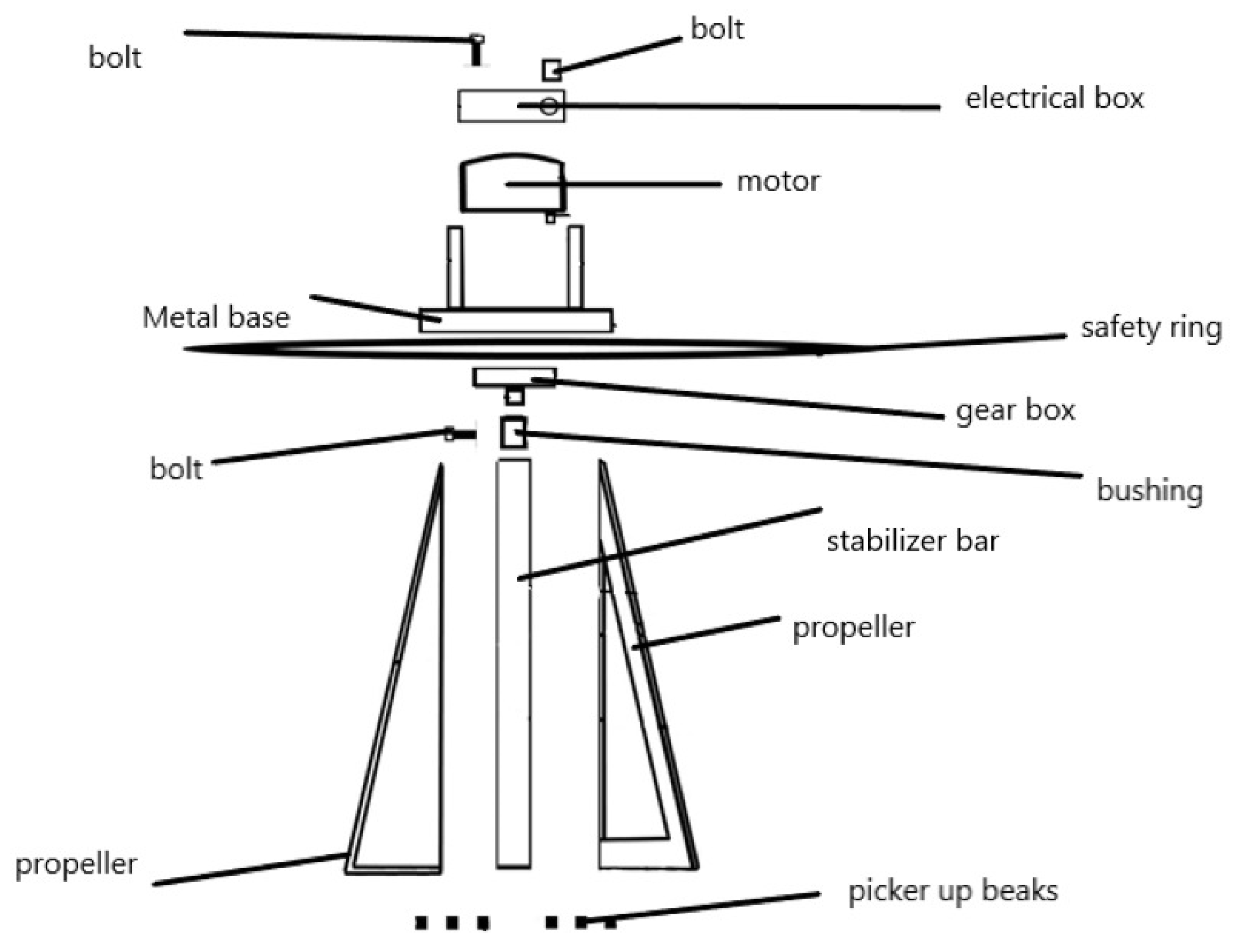
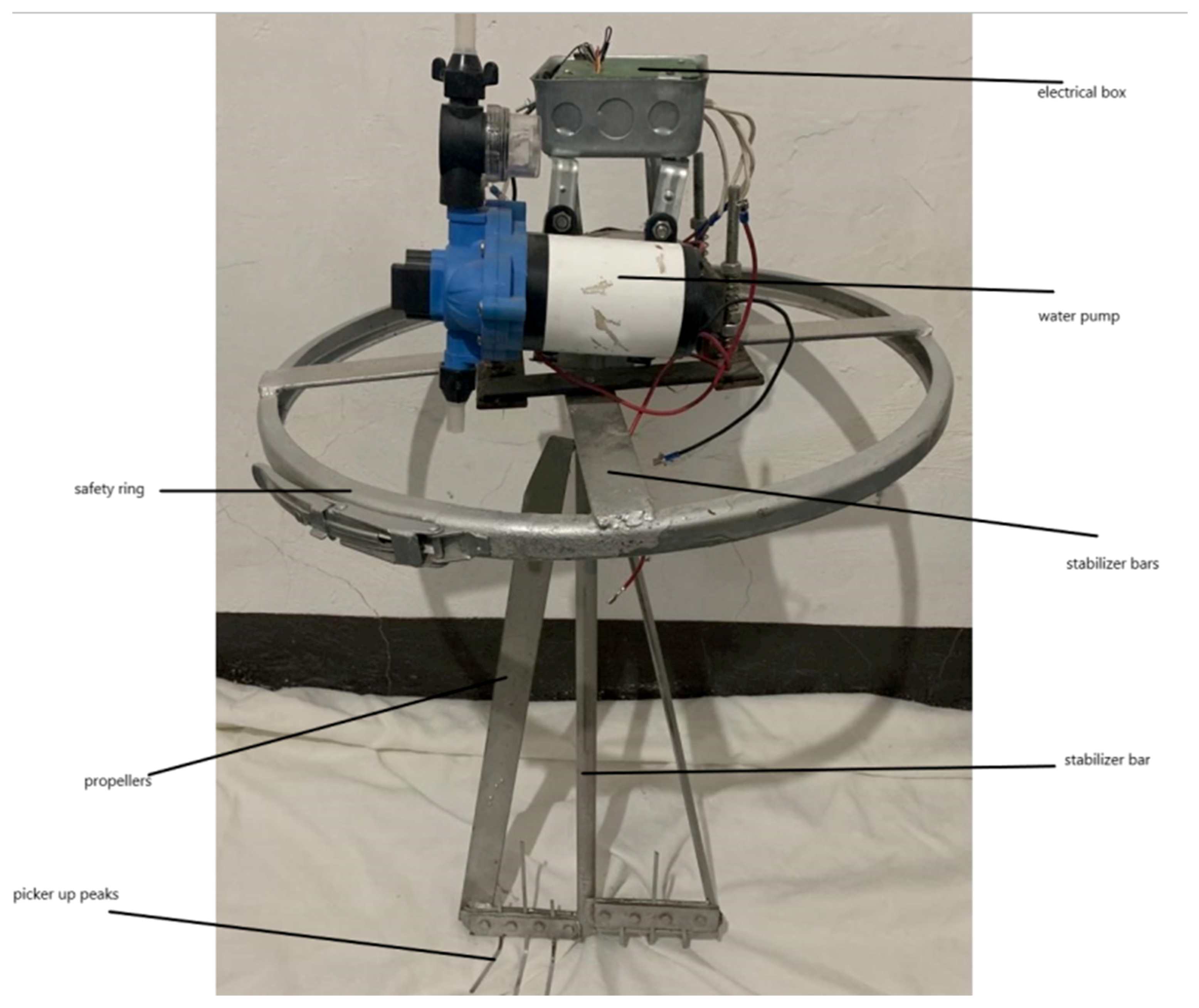
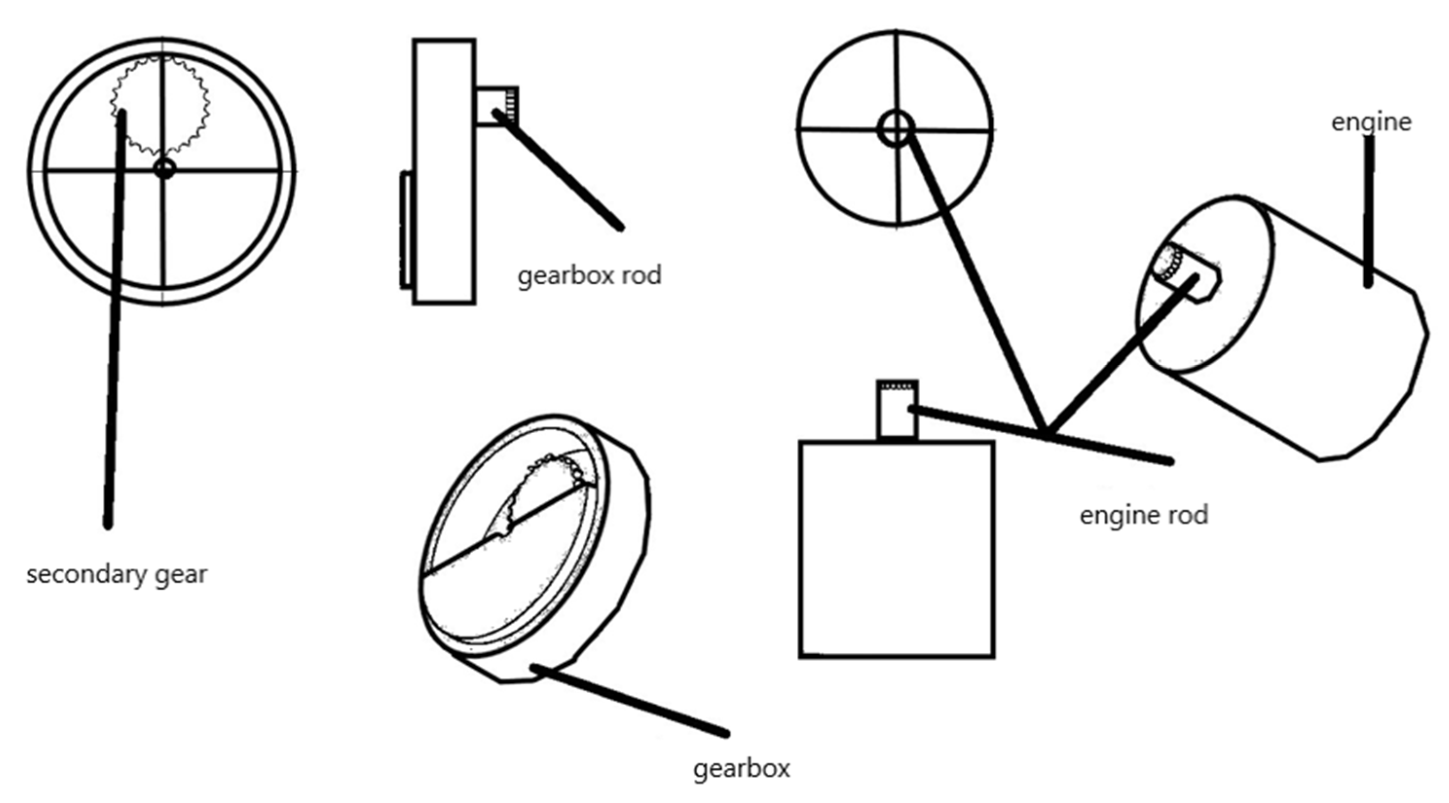
2.1. Tool Development
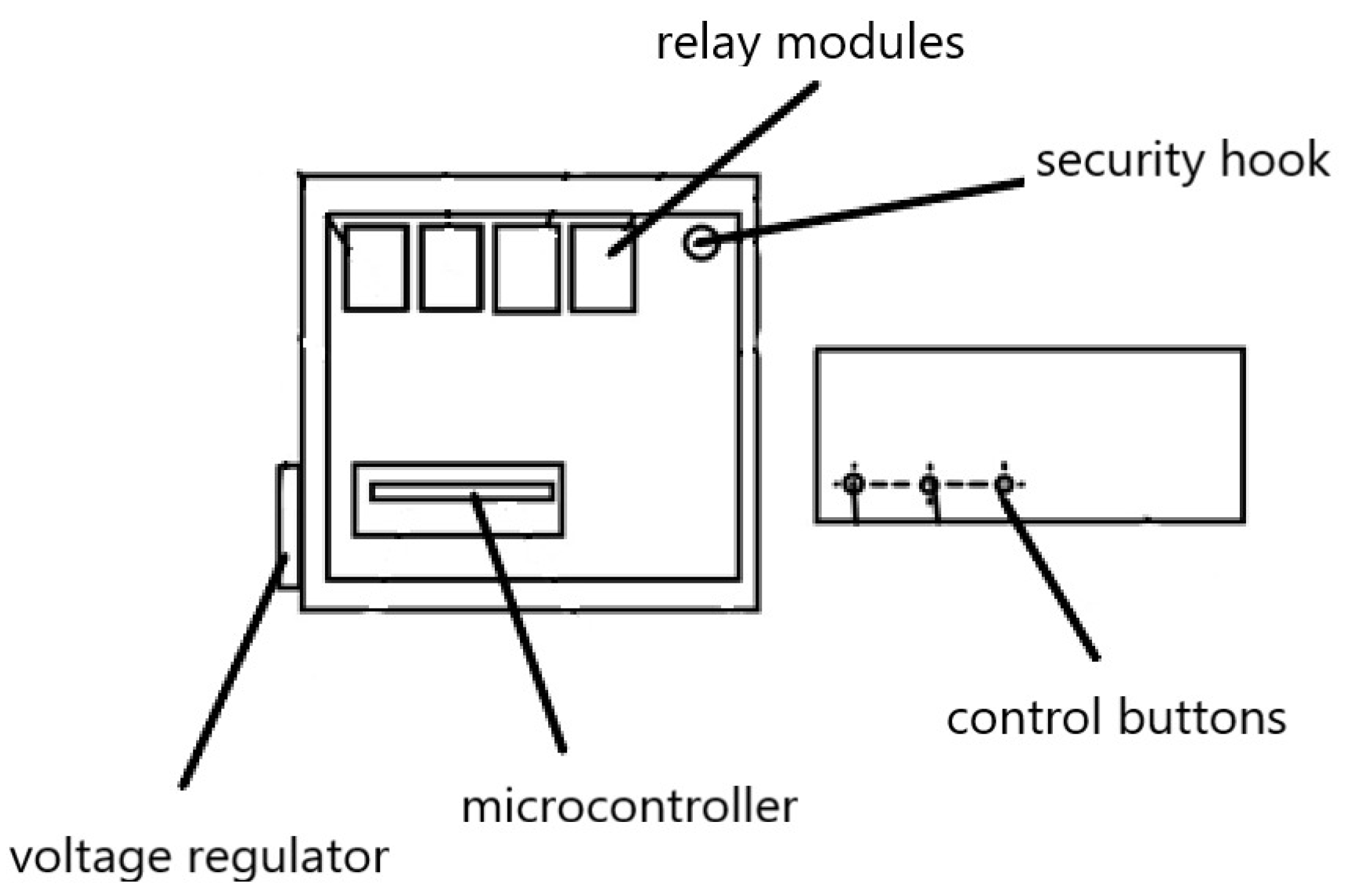
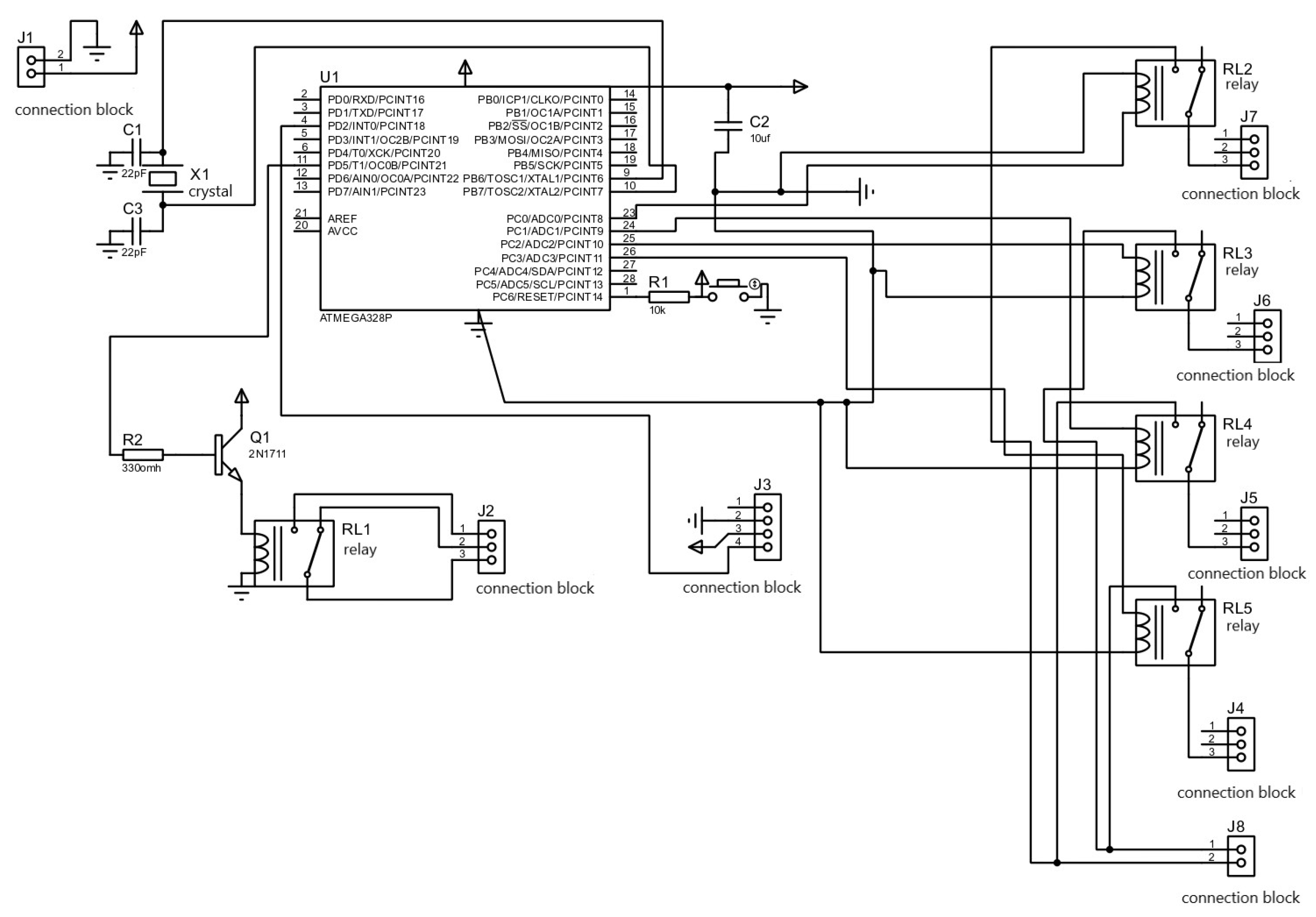
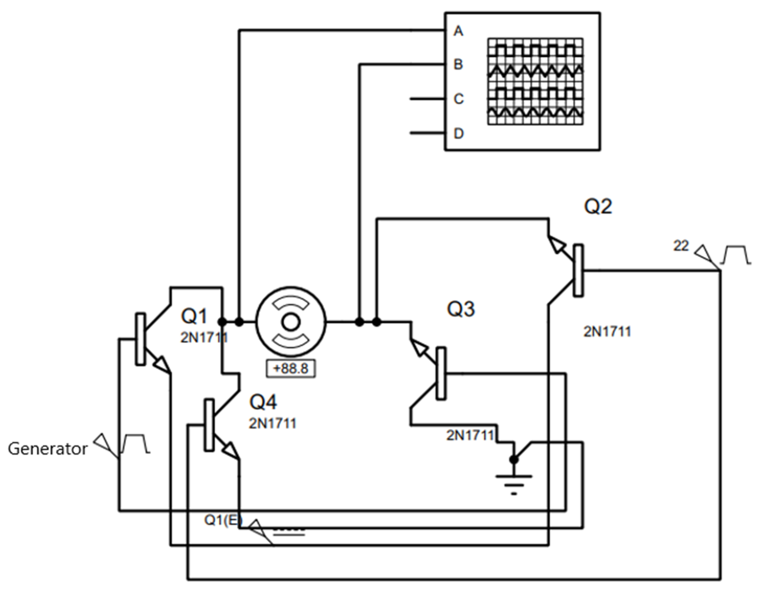
2.2. Electronic Stage
- Atmega328p, Microcontroller responsible for signal analysis and pulse sending.
- Four relay modules, used to alternate the flow of current.
- A 12–24v electric motor, responsible for generating the mechanical force for dissolution.
- ACS712 current sensor, used to interpret signals emitted by the motor.
- DC0-25V voltage sensor, module responsible for interpreting signals emitted by the motor.
- Four 2N1711 transistors, allowing the passage of 12-volt alternating the paths to avoid short circuits Figure 14.
- Four 2N2222 transistors, which function as switches to activate the relays.
- A 12v power supply, powering the circuit together with a regulator and the motor.
- A 12–5v voltage regulator, regulating the voltage that reaches the microcontroller.
- Three buttons, used to send signals to change the operating mode of the microcontroller.
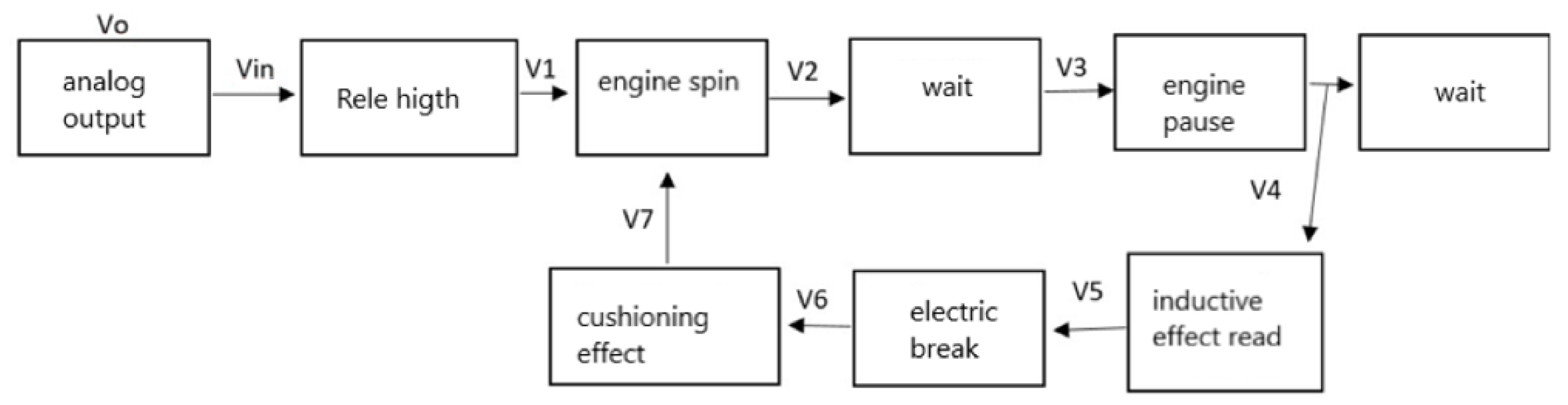
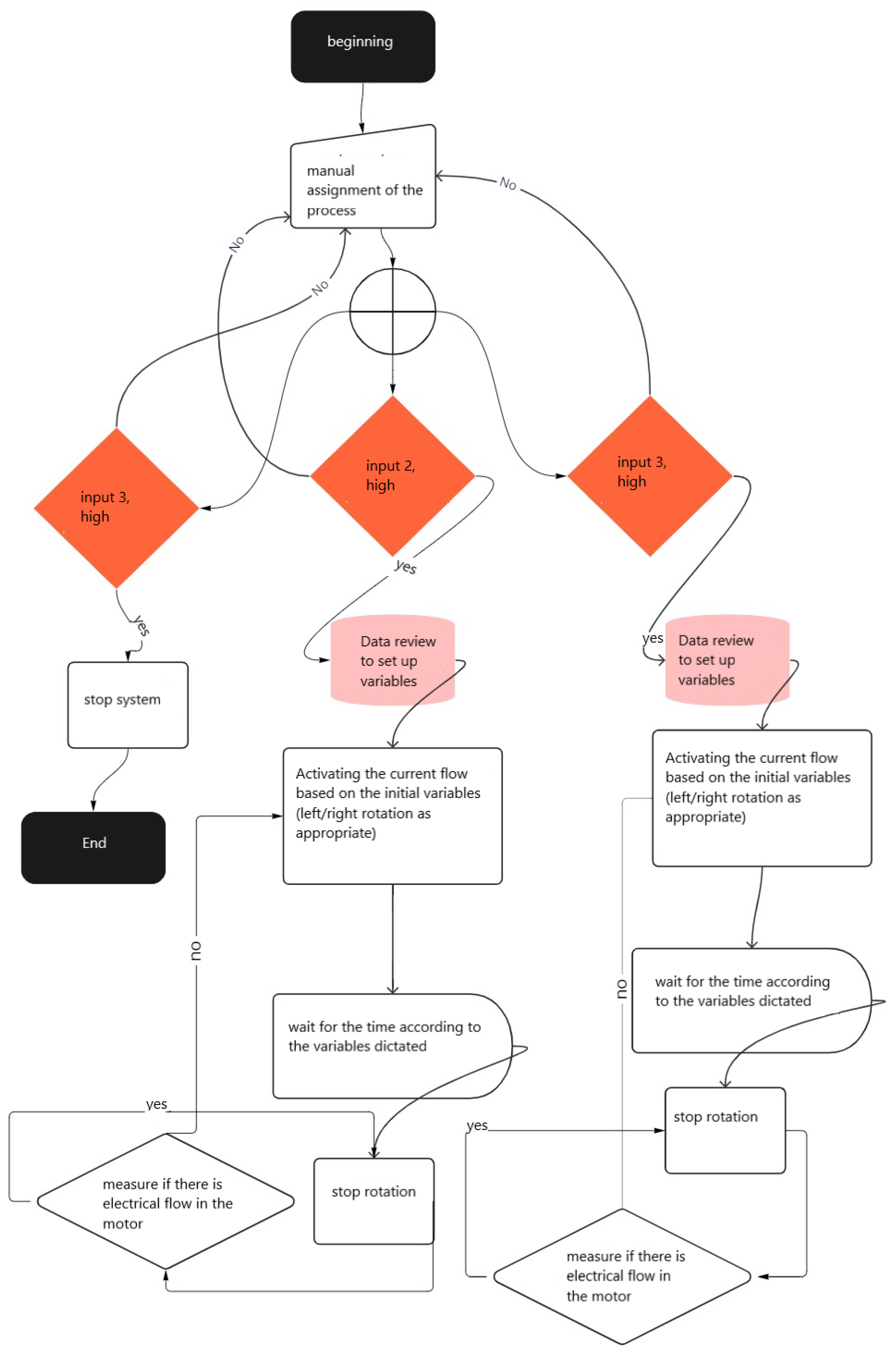
2.3. Logical Sequence of the Software for Controlling Turns
2.4. Experimental Test Layout
- (1)
- An agitator: considering the traditional method used by farmers to dissolve their fertilizers in water, which corresponds to an agitator, which can be made of wood or metal, in our case we use a wooden agitator and proceed to make the intervention.
- (2)
- Commercial mixing equipment for substances: there are many sizes, a manageable one for one person and with a power consumption available in most households (120 volts) or farms was chosen, which we know is not readily available in the field.
- (3)
- The proposed invention, the Automatic Fertilizer Dissolving Equipment, was designed to obtain the greatest amount of fertilizer dissolved in water in a shorter time.
3. Results
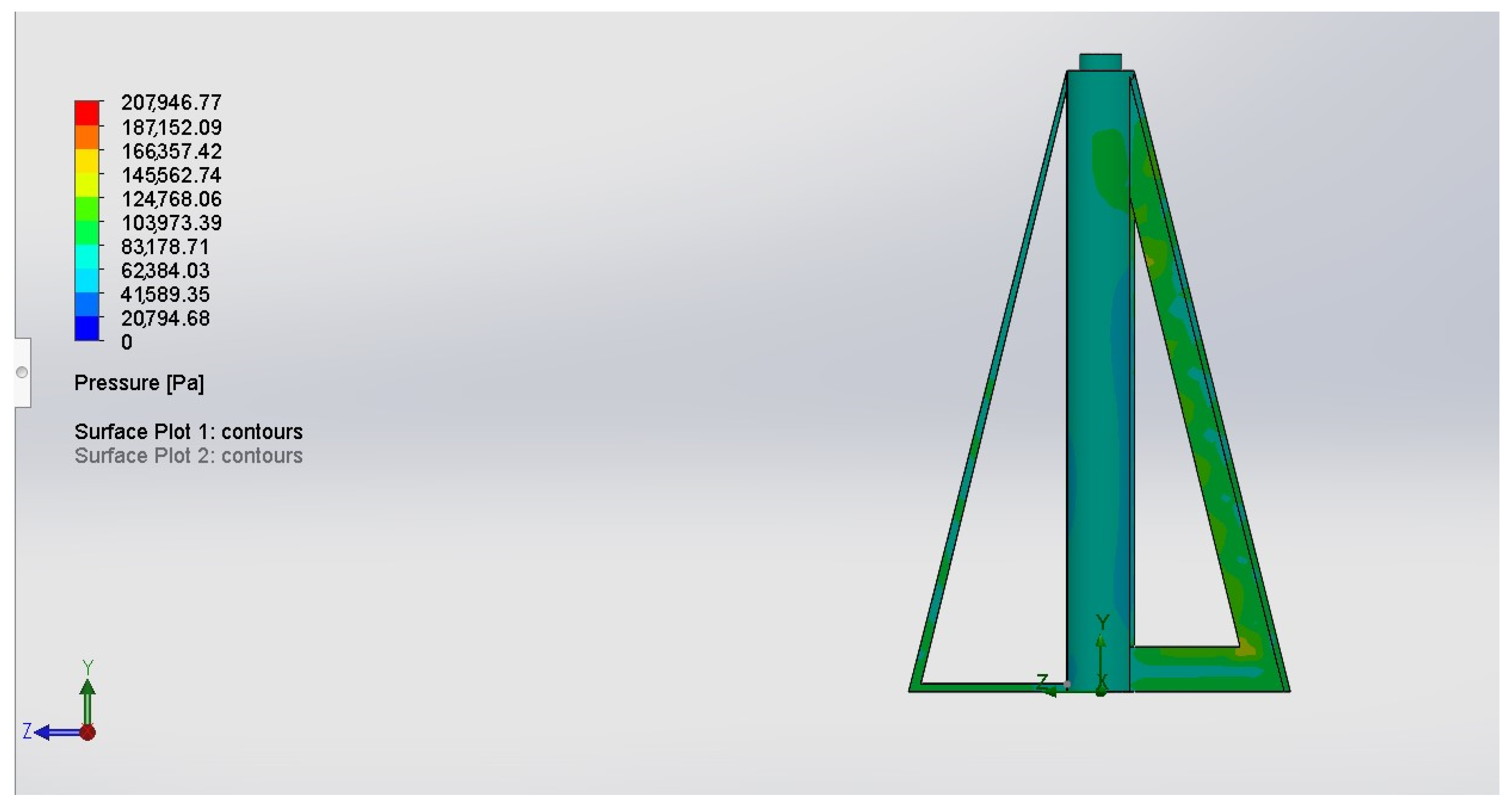
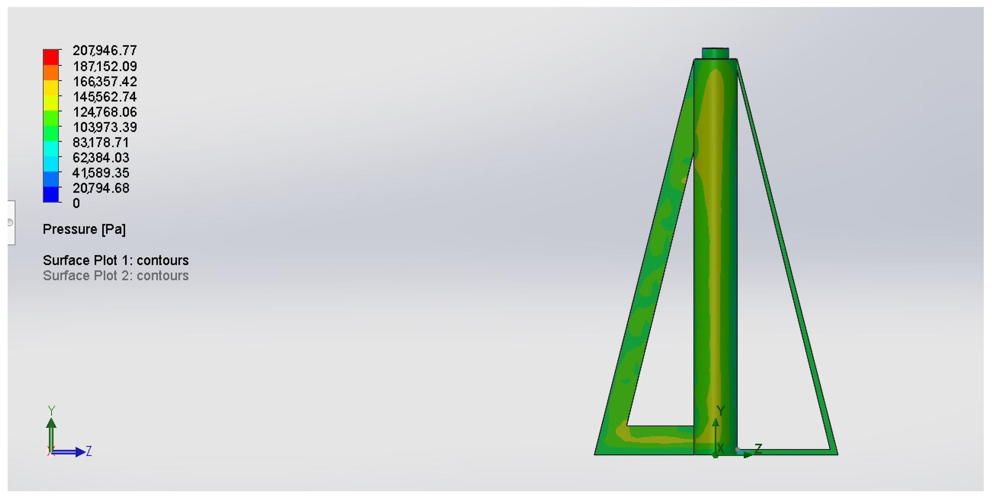
- Path: Liquids User Defined
- Density: 1.0267 kg/m^3
- Dynamic viscosity: 1.002 Pa*s
- Specific heat (Cp): 0.9 J/(kg*K)
- Thermal conductivity: 2.0000 W/(m*K)
- Cavitation effect: No
- Radiation properties: No
4. Discussion
5. Conclusions
6. Patents
Author Contributions
Funding
Data Availability Statement
Conflicts of Interest
References
- Allen, L.H.; Peerson, J.M.; Olney, D.K. Provision of multiple rather than two or fewer micronutrients more effectively improves growth and other outcomes in micronutrient-deficient children and adults. J. Nutr. 2009, 139, 1022–1030. [Google Scholar] [CrossRef] [Green Version]
- Imran, A.; López, S.; Magid, J.; Bruun, H.C. Dissolution kinetics of pyroaurite-type layered double hydroxide doped with Zn: Perspectives for pH controlled micronutrient release. Appl. Clay Sci. 2016, 123, 56–63. [Google Scholar] [CrossRef]
- Ferraris, G.N.; Couretot, L.A.; Toribio, M. IPNI CANADA. Available online: http://www.ipni.net/publication/ia-lacs.nsf/0/B5B2034B84BF8FF6852579950075F445/$FILE/19.pdf (accessed on 15 March 2022).
- Morales, E.J.; Rubí, M.; López, J.A.; Martínez, Á.R.; Morales, E.J. Urea (NBPT) una alternativa en la fertilización nitrogenada de cultivos anuales. Rev. Mex. De Cienc. Agrícolas 2019, 10, 1875–1886. [Google Scholar] [CrossRef] [Green Version]
- Lomelí, J. Informador.mx. Available online: https://www.informador.mx/ideas/Turbulencia-economica-abroche-su-cinturon--20220310-0035.html (accessed on 10 March 2022).
- BBC News Mundo. Available online: https://www.bbc.com/mundo/noticias-59579203#:~:text=Esa%20urea%20en%20concreto%20se,distintos%20usos%2C%20principalmente%20como%20fertilizante (accessed on 10 March 2022).
- Zahra, Z.; Habib, Z.; Hyun, H.; Shahzad, H.M.A. Overview on Recent Developments in the Design, Application, and Impacts of Nanofertilizers in Agriculture. Sustainability 2022, 14, 9397. [Google Scholar] [CrossRef]
- Adubor, N.V.; Adeniji, A.A.; Salau, O.P.; Olajugba, O.J.; Onibudo, G.O. Exploring Green Human Resource Adoption and Corporate Sustainability in Nigerian Manufacturing Industry. Sustainability 2022, 14, 12635. [Google Scholar] [CrossRef]
- Channabasav; Hampali, C.D. Numerical analysis of laminar to turbulent transition boundary layer flow. Mater. Today Proc. 2022, 54, 319–324. [Google Scholar] [CrossRef]
- Le, T.-T.-H.; Kang, H.; Kim, H. Towards Incompressible Laminar Flow Estimation Based on Interpolated Feature Generation and Deep Learning. Sustainability 2022, 14, 11996. [Google Scholar] [CrossRef]
- Singh, G.; Tang, P.; Cheng, S.; Chan, H.K.; Kourmatzis, A. From laminar to turbulent flow in a dry powder inhaler: The effect of simple design modifications. Int. J. Pharm. 2022, 616, 121556. [Google Scholar] [CrossRef]
- Li, H.; Yang, Y.; Crabbe, M.J.C.; Chen, H. The Characteristics of Dissolved Organic Matter and Soil Microbial Communities in the Soils of Larix principis-rupprechtii Mayr. Plantations in the Qinling Mountains, China. Sustainability 2022, 14, 11968. [Google Scholar] [CrossRef]
- Anthony, M.; Prasad, V.; Raju, K.; Alsharif, M.H.; Geem, Z.W.; Hong, J. Design of Rotor Blades for Vertical Axis Wind Turbine with Wind Flow Modifier for Low Wind Profile Areas. Sustainability 2020, 12, 8050. [Google Scholar] [CrossRef]
- Mitchell, S.; Ogbonna, I.; Volkov, K. Improvement of Self-Starting Capabilities of Vertical Axis Wind Turbines with New Design of Turbine Blades. Sustainability 2021, 13, 3854. [Google Scholar] [CrossRef]
- Adeola, O.M.; Ramoelo, A.; Mantlana, B.; Mokotedi, O.; Silwana, W.; Tsele, P. Review of Publications on the Water-Energy-Food Nexus and Climate Change Adaptation Using Bibliometric Analysis: A Case Study of Africa. Sustainability 2022, 14, 13672. [Google Scholar] [CrossRef]
- Figueroa, F.; Puente-Uribe, M.B.; Arteaga-Ledesma, D.; Espinosa-García, A.C.; Tapia-Palacios, M.A.; Silva-Magaña, M.A.; Mazari-Hiriart, M.; Arroyo-Lambaer, D.; Revollo-Fernández, D.; Sumano, C.; et al. Integrating Agroecological Food Production, Ecological Restoration, Peasants’ Wellbeing, and Agri-Food Biocultural Heritage in Xochimilco, Mexico City. Sustainability 2022, 14, 9641. [Google Scholar] [CrossRef]
- Chhinh, N.; Sok, S.; Sou, V.; Nguonphan, P. Local Engagement in the Agricultural Cooperatives (ACs) Operation in Cambodia. Sustainability 2022, 14, 16515. [Google Scholar] [CrossRef]
- Martins, J.; Gonçalves, C.; Silva, J.; Gonçalves, R.; Branco, F. Digital Ecosystem Model for GIAHS: The Barroso Agro-Sylvo-Pastoral System. Sustainability 2022, 14, 10349. [Google Scholar] [CrossRef]
- Ren, J.; Lei, H.; Ren, H. Livelihood Capital, Ecological Cognition, and Farmers’ Green Production Behavior. Sustainability 2022, 14, 16671. [Google Scholar] [CrossRef]
- Yan, Z.; Zhou, W.; Wang, Y.; Chen, X. Comprehensive Analysis of Grain Production Based on Three-Stage Super-SBM DEA and Machine Learning in Hexi Corridor, China. Sustainability 2022, 14, 8881. [Google Scholar] [CrossRef]
- Sohoulande, C.D.D.; Szogi, A.A.; Novak, J.M.; Stone, K.C.; Martin, J.H.; Watts, D.W. Long-Term Nitrogen and Phosphorus Outflow from an Instream Constructed Wetland under Precipitation Variability. Sustainability 2022, 14, 16500. [Google Scholar] [CrossRef]
- Putra, D.P.; Bimantio, M.P.; Sahfitra, A.A.; Suparyanto, T.; Pardamean, B. Simulation of Availability and Loss of Nutrient Elements in Land with Android-Based Fertilizing Applications. In Proceedings of the 2020 International Conference on Information Management and Technology (ICIMTech), Bandung, Indonesia, 13–14 August 2020; pp. 312–317. [Google Scholar] [CrossRef]
- Hashem, N.M.; Abdelnour, S.A.; Alhimaidi, A.R.; Swelum, A.A. Potential impacts of COVID-19 on Reproductive Health: Scientific Findings and Social Dimension. Saudi J. Biol. Sci. 2021, 28, 1702–1712. [Google Scholar] [CrossRef] [PubMed]
- Hafez, H.M.; Attia, Y.A. Challenges to the Poultry Industry: Current Perspectives and Strategic Future after the COVID-19 Outbreak. Front. Vet. Sci. 2020, 7, 516. [Google Scholar] [CrossRef] [PubMed]
- Hashem, N.M.; González, A.; Rodriguez, A.J. Animal Welfare and Livestock Supply Chain Sustainability under the COVID-19 Outbreak: An Overview. Front. Vet. Sci. 2020, 7, 582528. [Google Scholar] [CrossRef]
- Hussain, S.; Hussain, A.; Ho, J.; Sparagano, O.A.E.; Zia, U.-R. Economic and social impacts of COVID-19 on animal welfare and dairy husbandry in Central Punjab, Pakistan. Front. Vet. Sci. 2020, 7, 58997. [Google Scholar] [CrossRef]
- Ilinova, A.; Dmitrieva, D.; Kraslawski, A. Influence of COVID-19 pandemic on fertilizer companies: The role of competitive advantages. Resour. Policy 2021, 71, 102019. [Google Scholar] [CrossRef] [PubMed]
- Laskari, M.; Menexes, G.C.; Kalfas, I.; Gatzolis, I.; Dordas, C. Effects of Fertilization on Morphological and Physiological Characteristics and Environmental Cost of Maize (Zea mays L.). Sustainability 2022, 14, 8866. [Google Scholar] [CrossRef]
- Hashem, N.M.; Hassanein, E.M.; Hocquette, J.-F.; Gonzalez-Bulnes, A.; Ahmed, F.A.; Attia, Y.A.; Asiry, K.A. Agro-Livestock Farming System Sustainability during the COVID-19 Era: A Cross-Sectional Study on the Role of Information and Communication Technologies. Sustainability 2021, 13, 6521. [Google Scholar] [CrossRef]
- Preza-Fontes, G.; Wang, J.; Umar, M.; Qi, M.; Banger, K.; Pittelkow, C.; Nafziger, E. Development of an Online Tool for Tracking Soil Nitrogen to Improve the Environmental Performance of Maize Production. Sustainability 2021, 13, 5649. [Google Scholar] [CrossRef]
- Feodorov, C.; Velcea, A.M.; Ungureanu, F.; Apostol, T.; Robescu, L.D.; Cocarta, D.M. Toward a Circular Bioeconomy within Food Waste Valorization: A Case Study of an On-Site Composting System of Restaurant Organic Waste. Sustainability 2022, 14, 8232. [Google Scholar] [CrossRef]
- Beňuš, O.; Bielik, P.; Turčeková, N.; Adamičková, I. Sustainability of the Slovak Spirits Industry in the Single Market of the EU. Sustainability 2021, 13, 5692. [Google Scholar] [CrossRef]
- Jensen, E.S.; Hauggaard-Nielsen, H. How can increased use of biological N2 fixation in agriculture benefit the environment? Plant Soil 2003, 252, 177–186. [Google Scholar] [CrossRef]
- Omar, L.; Ahmed, O.H.; Boyie Jalloh, M.; Abdul Majid, N.M. Rice Husk Compost Production and Use in Mitigating Ammonia Volatilization from Urea. Sustainability 2021, 13, 1832. [Google Scholar] [CrossRef]
- Gebrehiwot, A.A.; Hashemi-Beni, L.; Kurkalova, L.A.; Liang, C.L.; Jha, M.K. Using ABM to Study the Potential of Land Use Change for Mitigation of Food Deserts. Sustainability 2022, 14, 9715. [Google Scholar] [CrossRef]
- Alhashim, R.; Anandhi, A. Global Warming and Toxicity Impacts: Peanuts in Georgia, USA Using Life Cycle Assessment. Sustainability 2022, 14, 3671. [Google Scholar] [CrossRef]
- Draad, A.A.; Kuiken, G.D.C.; Nieuwstadt, F.T.M. Laminar–Turbulent Transition in Pipe Flow for Newtonian and Non-Newtonian Fluids. J. Fluid Mech. 1998, 377, 267–312. [Google Scholar] [CrossRef] [Green Version]
- Potter, M.C.; Wiggert, D.C. Mecánica de Fluidos, 3rd. ed.; Thomson Learning: Boston, MA, USA, 2007. [Google Scholar]
- Silva, Y.F.; Valadares, R.V.; Dias, H.B.; Cuadra, S.V.; Campbell, E.E.; Lamparelli, R.A.C.; Moro, E.; Battisti, R.; Alves, M.R.; Magalhães, P.S.G.; et al. Intense Pasture Management in Brazil in an Integrated Crop-Livestock System Simulated by the DayCent Model. Sustainability 2022, 14, 3517. [Google Scholar] [CrossRef]
- Bhaskara, S.; Bawa, K.S. Societal Digital Platforms for Sustainability: Agriculture. Sustainability 2021, 13, 5048. [Google Scholar] [CrossRef]
- Baroudi, J.J.; Olson, M.H.; Ives, B. An empirical study of the impact of user involvement on system usage and information satisfaction. Commun. ACM 1986, 29, 232–238. [Google Scholar] [CrossRef]


| Tool | Power Source | Power | Time Required to Dissolve Solid Fertilizer | Percentage of Material Dissolved |
|---|---|---|---|---|
| Automatic fertilizer dissolving equipment | D/C 12 v | 250 w | 5 min (configuration D) | 99% |
| Commercial equipment | A/C 120 v | 1200 w | 15 min | 97% |
| Manual (using a stirrer) | N/A | N/A | 70 min | 90% |
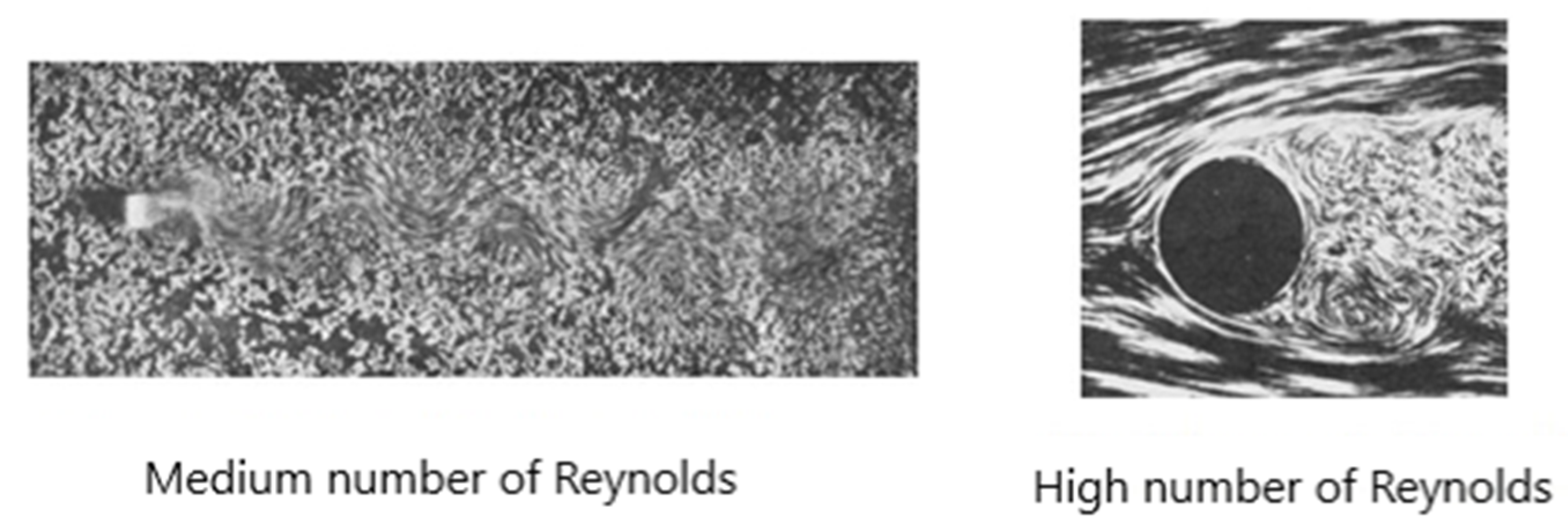
| Right Turn Time | Turn Speed | Centripetal Acceleration of Turn | Left Turn Time | Time o Dissolve Fertilizer | Pause Time between Turns | Turn Configuration Identification | Reynolds Number |
|---|---|---|---|---|---|---|---|
| 4 s, 2 s | 20 m/s | 13 m/s2 | 4 s, 2 s | 10–12 min | 10 s | A | 69,790 |
| 6 s, 2 s | 15 m/s | 7.5 m/s2 | 6 s, 2 s | 10–12 min | 6 s | B | 52,342.5 |
| 8 s, 2 s | 10 m/s | 3.3 m/s2 | 8 s, 2 s | 6–10 min | 4 s | C | 34,895 |
| 10 s, 3 s | 5 m/s | 0.8 m/s2 | 10, 3 s | 5 min | 3 s | D 1 | 17,447.5 |
| Duration Time for the Manual Dissolution of Salts | Duration Time for the Dissolution of Salts with the Invention | Percentage of Time Saved when Using the Invention |
|---|---|---|
| 70 min | 5 min | 92.85% |
| Duration Time for the Dissolution of Fertilizer Using a Commercial Stirrer | Duration Time for the Dissolution of Fertilizer with the Invention | Percentage of Time Saved when Using the Invention |
|---|---|---|
| 15 min | 5 min | 33% |
Disclaimer/Publisher’s Note: The statements, opinions and data contained in all publications are solely those of the individual author(s) and contributor(s) and not of MDPI and/or the editor(s). MDPI and/or the editor(s) disclaim responsibility for any injury to people or property resulting from any ideas, methods, instructions or products referred to in the content. |
© 2023 by the authors. Licensee MDPI, Basel, Switzerland. This article is an open access article distributed under the terms and conditions of the Creative Commons Attribution (CC BY) license (https://creativecommons.org/licenses/by/4.0/).
Share and Cite
Martínez García, M.; Ramos Cabral, S.; Pérez Zúñiga, R.; Martínez Rodríguez, L.C.G. Automatic Equipment to Increase Sustainability in Agricultural Fertilization. Agriculture 2023, 13, 490. https://doi.org/10.3390/agriculture13020490
Martínez García M, Ramos Cabral S, Pérez Zúñiga R, Martínez Rodríguez LCG. Automatic Equipment to Increase Sustainability in Agricultural Fertilization. Agriculture. 2023; 13(2):490. https://doi.org/10.3390/agriculture13020490
Chicago/Turabian StyleMartínez García, Mario, Silvia Ramos Cabral, Ricardo Pérez Zúñiga, and Luis Carlos G. Martínez Rodríguez. 2023. "Automatic Equipment to Increase Sustainability in Agricultural Fertilization" Agriculture 13, no. 2: 490. https://doi.org/10.3390/agriculture13020490