Article

Optimal Design and Testing of a Crawler-Type Flax Combine Harvester

College of Mechanical and Electrical Engineering, Gansu Agricultural University, Lanzhou 730070, China
*
Author to whom correspondence should be addressed.
Agriculture 2023, 13(2), 229; https://doi.org/10.3390/agriculture13020229
Submission received: 31 December 2022 / Revised: 12 January 2023 / Accepted: 13 January 2023 / Published: 17 January 2023
(This article belongs to the Topic Innovation and Solution for Sustainable Agriculture)

Abstract

:
China is a large flax-growing country, with planting area and production ranking among the top three in the world. However, the cultivation range of flax in China is very broad, complex, and diverse, resulting in different planting scales and patterns, making it difficult to apply foreign large combine harvesters, and China lacks a dedicated flax combine harvester. This research improved the design of the 4LZ-4.0 crawler-type flax combine harvester for the regional features and flax cropping patterns in China. First, the structure, technical parameters, and working principles of the machine were introduced; second, the theoretical analysis and optimization of key components were performed; and finally, with the advancing speed of the machine, the speed of the threshing drum, and the speed of the suction fan as independent variables and the rate of removal and the total loss rate as response values, a three-factor, three-level response surface analysis method was used. For each component and response value, a mathematical model was created, and the factors and their interactions were evaluated and confirmed. The results demonstrated that the three parameters impact the threshing drum speed, advancing speed, and centrifugal fan speed in that order of priority, as well as the total loss rate in that order of priority. The machine’s optimal operating settings were 1.5 m·s−1 advancing speed, 788.49 r·min−1 threshing drum speed, and 885.34 r·min−1 centrifugal fan speed, and the validation test results indicated that under the typical dryland dense flax cultivation mode, it had a 97.46% threshing rate and 2.99% total loss rate after the test. This demonstrated that optimizing operational parameters may decrease losses in the process of mechanical flax harvesting, enhance harvesting efficiency, and satisfy the marketable flax harvesting standards.

1. Introduction

Flax is farmed and utilized in over fifty nations worldwide because of its drought tolerance, adaptability, and high value [1,2,3]. At the moment, Asia and Europe have the most flax planting area, followed by the Americas, and the world’s average yearly flax planting area is essentially maintained at 2.58 × 10⁶ hm2. Canada’s planting area accounts for approximately 34.95% of the world’s total planting area. China accounts for roughly 19.70% of the world’s total planting area, the United States accounts for approximately 12.72% of the world’s total planting area, and India accounts for approximately 8.70% of the world’s total planting area. In recent years, the average area of flax planting in my country has stabilized at 2.92 × 10⁴ hm2, and the average yield of flax has reached 1275 kg·hm−2. It is mainly distributed in Gansu, Neimongu, Shanxi, and other provinces. Gansu Province is one of the main flax-producing areas in China. In 2020, the planting area of flax took up about 30.50% of the total planting area of the country, and the total output accounts for 38.67% of the country, both the sown area and the output rank first in China [4,5,6]. Due to the linen planting model, variety, and other factors, foreign grain combined harvesters cannot fully meet the needs of domestic linen mechanized harvest. There are problems such as cutting table entanglement, bridge blocking, difficulty in removing granules, losses, and other problems [4,5,6].
Agricultural machinery manufacturers in Europe and the United States have designed numerous models for flax characteristics, mostly with two-stage harvesting and combined harvesting technologies, such as Case flax cutting and spreading operators, John Deere traction flax picking combine harvesters, John Deere self-propelled flax picking combines harvesters, and so on [6,7]. Jerzy Makowski et al. [7] tested the effect of choosing combined harvesting after flax tilling and found that combined harvesting after tilling did not influence flaxseed yield or weight; however, the height of the cut stubble determined the production of homogenous fiber. The existing grain combine harvester had a wide range of working parameter adjustments in combined harvesting, including the rotation speed of the paddle wheel, the speed of the cutter blade, the advancing speed of the operator, the speed of the threshing drum, the speed of the cleaning fan, and the shaking line speed of the cleaning double layer sieve, which can be steplessly adjusted to achieve the modular parameters of the flax combine harvester according to the different types of flax [6,8]. The level of combined harvesting technology in Europe and the United States is higher than in China, and combine harvesters are large and expensive. Such large machines are not adapted to China’s flax-growing environment, limiting the machine’s role and benefits. The high selling price also reduces farmers’ desire to buy. In China, Song et al. [9] built a basic small-scale feed drum threshing machine for flax and grain millet based on the demands of the production and operation mode of tiny grains in Shanxi Province, which was inefficient and inappropriate for threshing operations in vast flax cultivation regions. Wang et al. [10,11] refined the structure and features of a semi-repeated wheat thresher and designed and tested a 5TS-50 semi-repeated mixed grain thresher. This type of machinery can only minimize the work intensity of the decision, and cutting and transporting were also labor-intensive tasks. Zhao et al. [12] carried out structural design and parameter optimization of the threshing mechanism of a self-propelled flax threshing tiller based on the existing mechanism, which is only one of the two harvesting modes and does not have high operational efficiency. Liu et al. [13,14] designed a cut-and-sun machine for flax harvesting according to the topographical characteristics of flax cultivation. Qu et al. [15,16] designed a full-feed flax thresher based on the traits of the flax plant. Dai et al. [17,18,19] conducted basic research on the biomechanical characteristics of flax stalks, seed floating tests, seed discrete element parameter calibration, and the wind sorting mechanism of the threshing material, and developed a threshing material scavenger to improve the mechanized operation process of flax sectional harvesting. The machine developed by the above researchers was developed for the segmented harvesting mode of flax, which is used in small areas of flax at such times, but the operational efficiency is lower than combined harvesting when large areas are planted. At the same time, Zhao et al. [20] developed China’s first large flax combine harvester for the flax cultivation pattern in the watered land of the Hexi tank area, which used a combined tangential flow + cross-axis flow threshing drum, double-layer anisotropic reciprocating vibrating screen, and a compound stripper to achieve one-time operations such as flax cutting and feeding, threshing and separation, grain collection, and transportation [20]. This kind of machine solves the flax harvesting problem of large-scale planting linen in the plain area, which greatly improves the harvest efficiency of linen. However, this machine is for a large volume. Carrying out the flax harvesting work so that the linen of the hilly areas also relies on artificial harvesting and transportation, has increased the cost of linseed planting, which seriously affects the enthusiasm of farmers and the development of the linen industry.
This study targets the land conditions and planting models planted by the linen hills in Gansu Province, China, and it suggests whether theoretical analysis, institutional design, and improvement can be carried out for the present commercial flax harvesting machine. Mixed selection, anti-entanglement device cutting, high-efficiency learning devices, and minor differences were produced in the study effort, and the mixed selection devices were optimized. If this machine is improved, it can meet the combined harvest of the hilly areas, and be extremely useful for the automated harvest of hilly mountains.

2. Materials and Methods

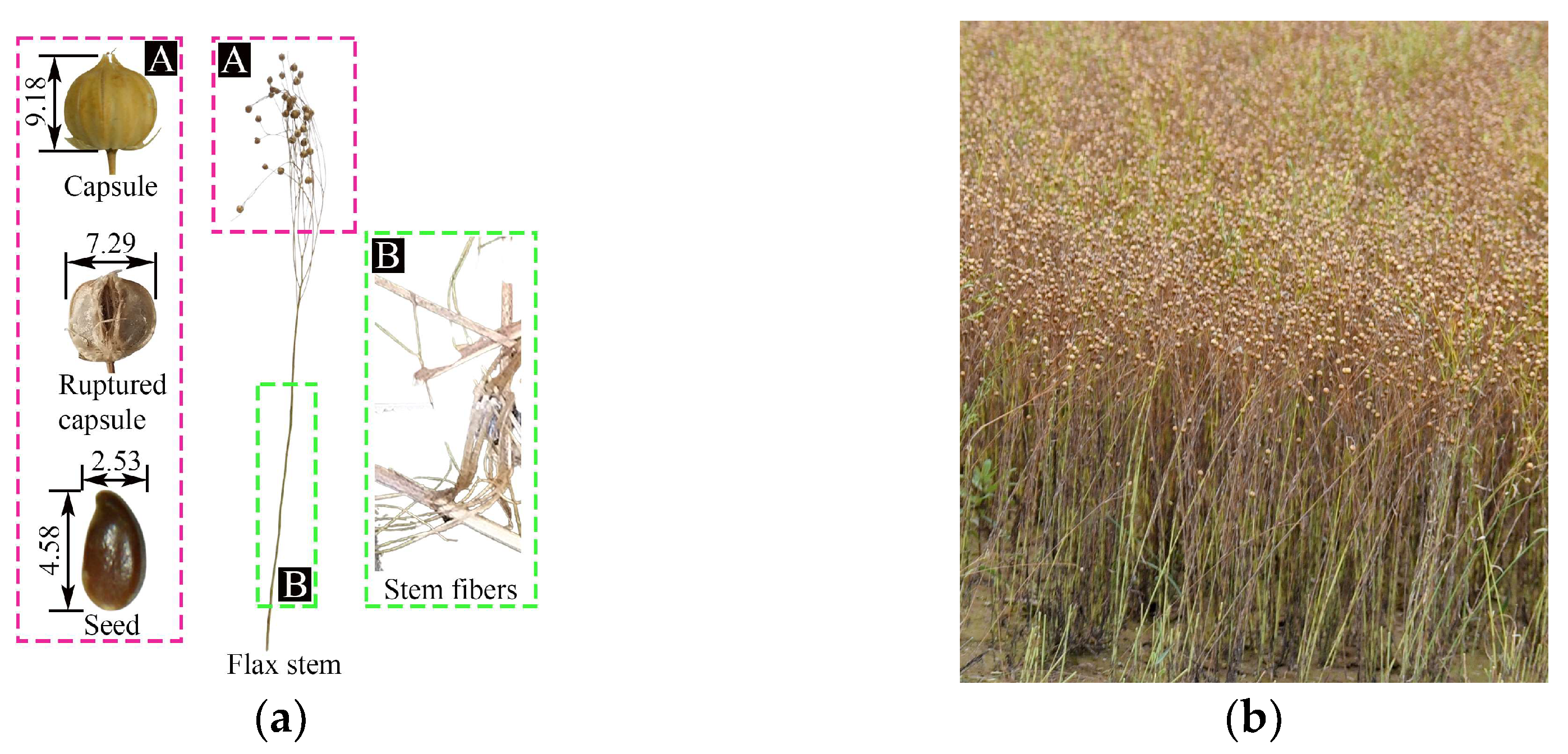
2.1. Flax Cultivation Patterns in the Hilly Areas

At the moment, the flax planting method for hilly areas is widely used. The percentage of usable flax out of flax harvesting is only around 60%, which is affected by factors such as planting environment, soil quality, and pests. The benefits of output and the spacing and plant spacing are reduced compared with the field planting model. Taking the Longya No. 9 flax gripped in the dry land dense planting model as an example, the average plant height is 472.33 mm, the average number of capsule fruits of a single plant is 8 to 13, and the planting density is 714 per square meter, as shown in Figure 1. The planting areas in hilly areas are small, the roads are narrow, and the large combine harvesting machine is difficult to operate. The space layout and power of small combine harvesting machines are limited, and the flax stems contain a large amount of cellulose. At the same time, the fruits of the capsule are intertwined with each other. When the flax harvest is harvested, it is easy to cause the roots, the middle stems, and the neck stems to be broken and fragmented, affecting the difficulty of selecting the system of the harvester.

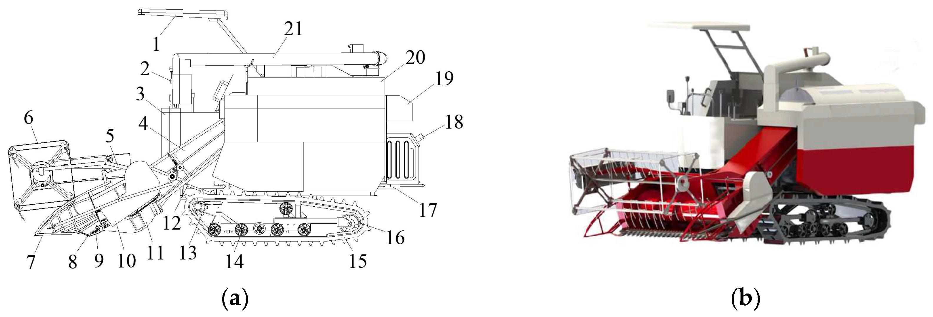
2.2. Crawler-Type Flax Combine Harvester Structure

The 4LZ-4.0 flax combine harvester is ideal for combined flax harvesting in river irrigation areas and hilly areas of the Loess Plateau. The machine has a crawler system, an anti-tangle cutting platform, a longitudinal axial flow threshing drum with ribs and teeth, a narrow grating separating concave plate, and a double-layer reciprocating vibrating screen that can be used for cutting, feeding, conveying, threshing, separating, sorting, and transporting flax all at the same time. The harvester has hydraulic steering and infinite variable speed, 360° in situ steering, and a turning radius of 1080 mm. An anti-tangle cutting table allows for easy flax plant feeding. The threshing drum is a longitudinal axial flow structure with ribs and teeth and a narrow grid separator plate for efficient and low-loss threshing and flax capsule and seed separation. To achieve small differences in the flax offcuts mixed cleaning operations, the cleaning system consists of a fan and a double-decker reciprocating vibrating screen combined to form a compound wind screening unit. The schematic structure and physical diagram of the entire machine are depicted in Figure 2, while the technical parameters are depicted in Table 1.
The 4LZ-4.0 flax combine is powered by a 4D2TI01 51.5 kW diesel engine. The header splitter goes to the flax stalk to split the grain and is supported by the wheel tines to the reciprocating cutter to cut the flax rootstalk, which is then transported by the spiral churn to the bridge and then transported by the chain rake to the flax stalk and cob threshing drum. The flax plant is threshed by the combined threshing drum by striking and rubbing the stalk, glumes, and seeds, after which the flax material is separated into layers by the rod and tooth separation section. After threshing the flax seeds, short stalks, and cereals from the narrow grid concave plate aperture into the cleaning device, stalks come out of the machine in the role of the grass guide plate. The flax from the material in the quality of the lighter short stalks, glumes, and light impurities is blown out of the machine by the fan in the cleaning device, and the flax from the material in the quality of the heavier flax seeds, long stalks, not of the clean flax capsule, is placed into a double layer of reciprocating vibrating sieve, flax seeds after the role of the upper and lower sieve are placed into a seed screw conveyor and transported into the grain bin. When the grain bin becomes saturated, the flax seeds are unloaded from the grain unloading cylinder onto the grain truck. Then all operations of the 4LZ-4.0 combine harvester are completed.

3. Analysis of the Working Process and Selection of Key Parameters

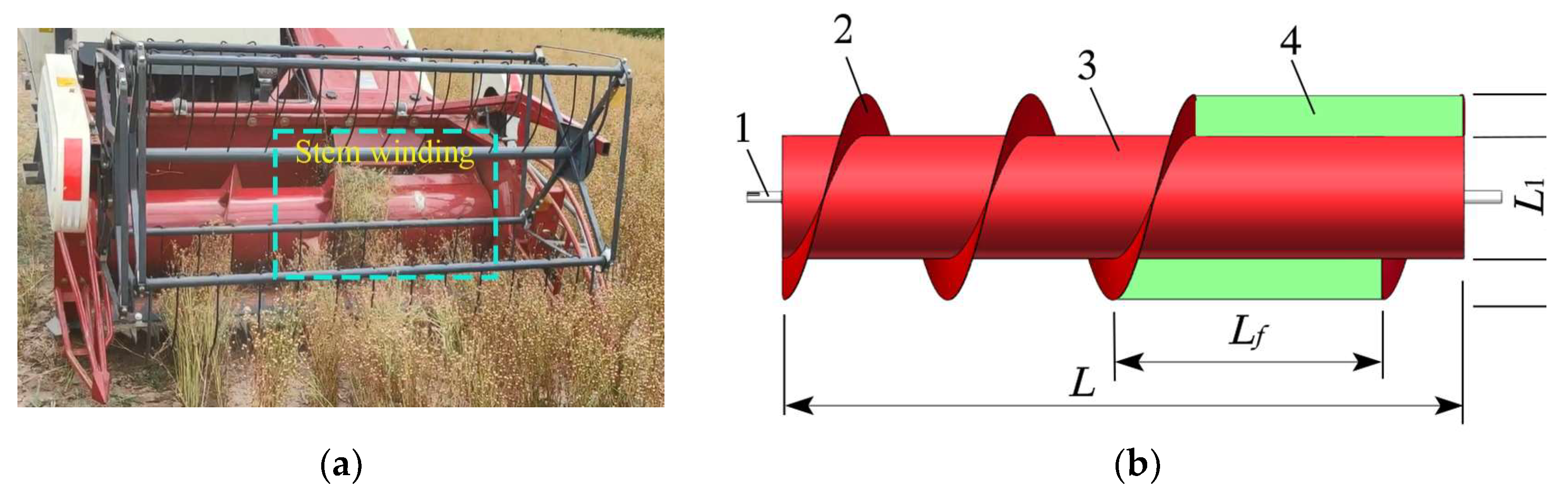
3.1. Selection of Cutting Table Working and Anti-Tangle Device Parameters

When the flax is harvested, the header is responsible for cutting the linseed stalks and then transporting the linseed stalks to the spiral conveyor. The linen stalks are in an upright state when the cutting is cut. For delivery the stalks are wrapped around the transportation dragon, causing the flax of the stalks to be blocked, and the subsequent work cannot be performed. Therefore, this study is carried out to improve the structure of the conveying churn’s feeding section by adding two 100 mm high anti-winding plates to the feeding section, which is designed to be movable and adjustable using bolts (Figure 3). The churn length is L = 1610 mm without the anti-wrap plate, the diameter is L1 = 300 mm, and the churn perimeter is C1 = 942.48 mm. The number of telescopic teeth in the feeding section was reduced to reduce the hanging phenomenon, while the number of telescopic teeth in other positions remained unchanged [21]. The churn is designed for a speed of 216 r·min−1 to avoid cutting table vibration and grain loss caused by churn rotation, and the spiral blades of the churn are fabricated of stainless steel with a thickness of 3 mm. The flax harvester is designed for an engine speed of 2400 r·min−1, an advancing speed of 1 m·s−1, a paddle wheel speed of 40 r·min−1, a cutting deck churn speed of 216 r·min−1, a threshing drum speed of 694–833 r·min−1, a centrifugal fan speed of 894 r·min−1, and a vibrating screen shaft speed of 477 r·min−1 when operating.

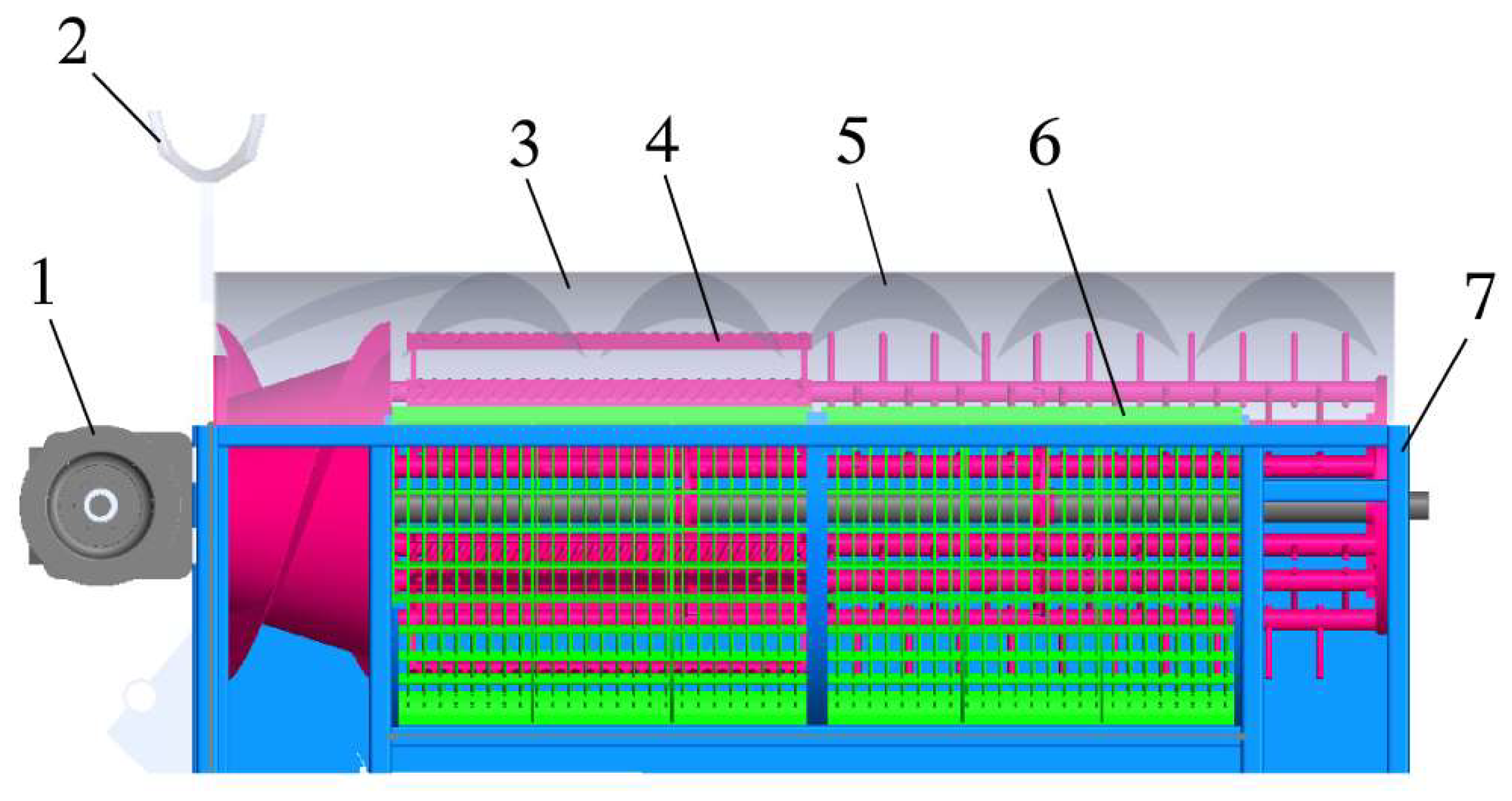
3.2. Analysis of the Working Process and Selection of Parameters of the Combined Threshing Unit

Existing combine harvesters have two forms of threshing devices: cross-axis flow and longitudinal axial flow, and threshing elements such as ribs and spiked teeth. The flax plant is tough and strong, and the length of the cross-axis flow threshing drum is limited by the width of the machine, making it difficult to increase threshing capacity, while the length of the longitudinal axial flow threshing drum is less affected by the length of the machine and can significantly increase threshing capacity. The grain threshing drum has a high threshing capacity but a low separation capacity and a high damage rate, while the spiked tooth drum has a low threshing capacity but a high separation capacity. For the flax difficult to thresh, difficult to separate, and easy to damage, the characteristics of the 4LZ-4.0 flax combine harvester threshing device uses a combination of ribs-rod teeth and longitudinal axial flow threshing drum. When the threshing device is working, the flax material enters the threshing chamber and is threshed under the action of the threshing element and the narrow grating common concave plate, the broken flax straw moves axially with the threshing drum and is discharged from the machine under the action of the deflector plate, the flax seeds fall into the cleaning device through the concave plate aperture. The structure of the threshing device is shown in Figure 4.

3.2.1. Screw Feed Head

The spiral feed head uses rotating blades to push the flax plant into the threshing chamber, and its design parameters affect operational efficiency. An analysis of the forces on the flax plant and the spiral blades is shown in Figure 5.
In flax plants and spiral blades, there is a frictional force f and normal thrust T, the combined force of the F and T deviates from an angle β, that is the frictional angle between the flax plant and the spiral blades, the conveying capacity of the spiral blades determines the smoothness of the transport of materials from the over-bridge to the threshing drum. To enhance the conveying capacity of the screw blade, this study used a conical screw feeding head while the axial conveying capacity of the screw blade needs to be greater than the combined feed [22], the mass of flax transported per unit time of the screw feeding head Q and the threshing drum speed n is calculated as:
Q = π 24 d 2 2 d 3 2 d 1 2 j S n ρ h C p × 10 10 n = 6 × 10 4 v π D
where d3 is the spiral blade and shell clearance in mm; S is the spiral blade pitch in mm; j is the material filling factor, taken 0.6–0.8; n is the threshing drum speed in r·min−1; ρh is the density of flax in kg·m−3; C is the threshing drum tilt conveying coefficient, taken 0.3; p is the spiral blade hood shell wrap angle coefficient, spiral feeding head part of the shell wrap angle of 180°, taken as 0.5 [23]. v is the linear speed of the threshing drum in m·s−1, concerning grain, wheat, etc., taken as 20 to 24 m·s−1 [5,21].
To ensure the smooth transport of flax for feeding, the conveying force needs to be greater than the resistance, with:
T cos α > f sin α f = T cos β α < 90 ° β = 68 °
The spiral lift angle affects the efficiency of the crop transport and the power consumption of the threshing device; therefore, the power consumption should be reduced as much as possible under the premise of ensuring smooth transport.
L 3 = P / Z 0 L 3 = π d 2 tan α
where P is the spiral feed head lead in mm; Z0 is the number of spiral feed heads, taken as 2.
Through the spiral blade on the flax plant force analysis and Equations (1)–(3) it can be seen that when the spiral feed head structural parameters are certain, flax in the spiral feed head convey capacity mainly through the threshing drum speed and spiral feed head unit volume operation to determine the quality of flax. In this study, the outer diameter of the spiral blade is 550 mm, the inner diameter of the spiral blade is 292 mm, the spiral feeding taper angle is 28°, the clearance between the spiral blade and the shell is 10–80 mm, the spiral blade pitch is 480 mm, the flax density is 480 kg·m−3, the speed range of the threshing drum is 694–833 r·min−1 as calculated by Equations (1)–(3), the maximum feeding volume Q = 4 kg·s−1, spiral feed head length L3 = 240 mm, spiral blade lift angle α = 7.9°.

3.2.2. Threshing Drum

The threshing drum is the core part of the combine, determining threshing quality and productivity and affecting the cleaning effect [24]. Based on the biomechanical characteristics of the flax plant, the 4LZ-4.0 flax combine uses a combined longitudinal axial flow threshing drum. The threshing element is laid out in a striker-tooth space, with the striker section responsible for the separation of the flax capsule from the seeds and the tooth section responsible for the separation of the flax seeds from the stalk impurities. The combined threshing element enhances the rubbing and squeezing of the flax capsules, and reduces impact and damage, while the narrow grid concave plate increases the cleaning efficiency and makes threshing and separation more efficient. The combined longitudinal axial flow threshing drum with rib teeth consists of a ribs-threshing element, a teeth-threshing element, spokes, and a crossbar, etc. The structure is shown in Figure 6.
The threshing effect of the threshing drum is inextricably linked to the diameter and length of the drum, which directly determines the threshing and damage rates. The formulae for calculating the length of the threshing drum are:
L t Q / q 0 L t = L 3 + L 4 + L 5 + L 6
where q0 is the feeding volume that the threshing drum is allowed to bear per unit length in kg∙s−1∙m−1, generally the axial threshing drum q0 is taken as 1.5–2 kg∙s−1∙m−1, and the combined harvester q0 is taken as 3–4 kg∙s−1∙m−1 [25].
In this study, q0 = 3 kg∙s−1∙m−1 and the threshing drum length Lt = 1350 mm, were calculated from the structural dimensions of the machine and Equation (4).
The diameter of the threshing drum affects the threshing and separation performance. The drum diameter of commonly used combine harvesters is 450–600 mm, and in this study, the diameter of the threshing drum was designed to be D = 550 mm.
The formulae for calculating the number of ribs Z are
Z = π D S 1
where S1 is the striker spacing in mm according to the diameter of the threshing drum and the striker arrangement, S1 = 280 mm.
The number of ribs Z = 6 is calculated from Equation (5). Different striker lengths and roller speeds of flax materials are kneaded and extruded, striking different layering effects, which in turn affects the rate of linen removal, impurity rate, damage rate, and loss rate. The working length of the striker L4 is calculated as
L 4 = Z n L t μ 0 60
where Lt is the length of the threshing drum in mm; μ0 is the threshing capacity of the striker per unit length in kg∙s−1∙m−1, 0.018 to 0.024 kg∙s−1∙m−1 is often used.
From Equation (6) it is calculated that L4 = 450 mm, from which it can be obtained that the feeding section L3 = 240 mm, the striker threshing section L4 = 450 mm, the rod and tooth separation section L5 = 550 mm, and the grass discharge section L6 = 110 mm. To make the threshing sufficient, the rod and tooth are installed symmetrically, the spacing between the nail teeth L7 = 70 mm, the working height of the nail teeth L8 = 66 mm, and the actual speed of the threshing drum is set according to the maturity of the crop.
The threshing drum cover is set above the threshing drum and combined with the threshing drum to form a closed threshing chamber, the role is to guide the broken flax stalk with the threshing drum axial movement out of the machine. The larger the angle, the less contact between the flax and the threshing element, and the more entrainment losses; the smaller the angle, the longer the flax plant stays in the threshing chamber, the higher the rate of seed impurities, and the increased threshing power loss. To make the flax threshing process smooth and reduce flax threshing entrainment losses, this study took the angle of the deflector at 45°.

3.2.3. Narrow Grille Recesses

After the flax plant passes through the threshing drum and the concave plates, the stalk, the threshing material, and the seeds are initially separated, and the light and fine residues in the threshing material and the seeds are cleaned and re-screened by the cleaning device. Therefore, the combination and arrangement of the concave plates play a decisive role in the separation effect of threshing and determine the loss rate, trash content, and other indicators [26]. The narrow-grid concave plate (Figure 7) is used in conjunction with the combined threshing drum to complete the threshing and separation of flax during the operation of the threshing unit. Due to the flexibility and strength of the flax stalk and the flattened shape of the flax seeds, the concave plate is designed as a narrow grid concave plate for efficient threshing and fast separation [14,27].
The design was based on the physical properties of flax capsules and seeds with a grating spacing of ds = 10 mm and a spacing of dh = 40 mm between the cross partitions. the area of the concave plate determines the threshing performance and the size of the screen apertures affects the rate of removal, the rate of damage to the threshing, the durability of the concave plate, and the reliability of the work. A larger concave plate area makes the separation of threshing more efficient [28]. The arc length l of the concave plate and the area A of the concave plate are calculated as:
l ( 1 δ ) q 1 0.6 q a A = B l
where q1 is the threshing device feeding volume in kg·s−1, taken 4 kg·s−1; β is the proportion of flax seeds in the feed material, taken 0.35; qa is the unit concave plate area can withstand the feeding volume in kg·s−1, taken 5 kg·s−1; B is the concave plate width in mm; and l is the concave plate arc length in mm.
The width of the concave plate is equal to the length of the threshing and separation section, i.e., B = 1150 mm, and the arc length of the concave plate is one-half of the circumference of the plate, which is calculated to be l = 860 mm.
The angle of the concave plate affects the threshing operation, the appropriate angle of the concave plate can ensure smooth threshing of flax and no blockage. While the separation is more complete, the entrapment loss is lower. Full-feed longitudinal axial flow threshing device concave plate sieve wrap angle is mostly 120° to 240°. Concave plate angle τ is calculated as:
τ = 360 l π D
From the Equation (8) calculation can be obtained, the concave plate wrap angle τ is 179°, and the actual design uses 180°. Considering the high toughness and strength of the flax stalk, the large feeding volume of the concave plate, the threshing drum load and impact, easily damage the concave plate, so the concave plate gap is set to adjustable, the adjustment range of 8–15 mm.

3.3. Analysis of the Working Process and Selection of Parameters of the Combined Cleaning Device

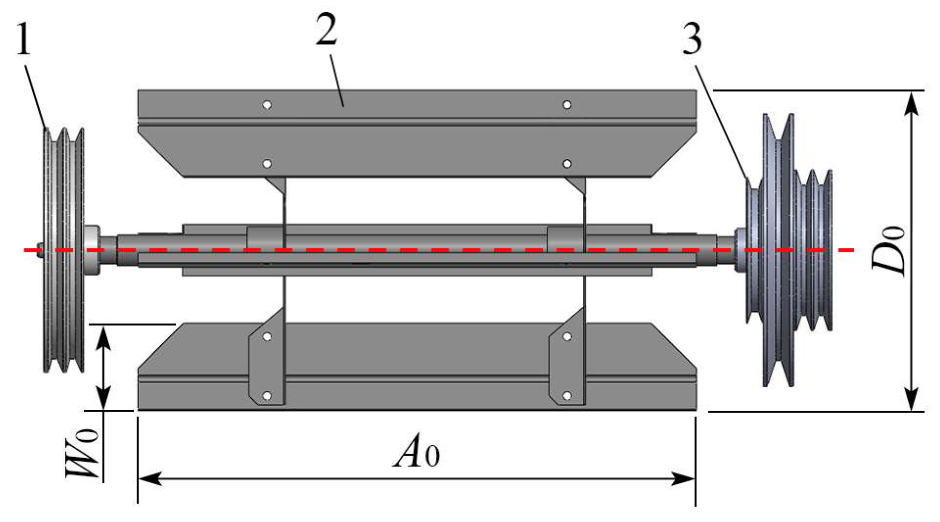
3.3.1. Structural Design

The performance of the cleaning device, as a key component of the combine, has a direct impact on harvesting efficiency [29]. Flax seeds and glumes in flax off-cuts do not differ significantly in terms of suspension rate and mixing, and it is difficult to separate them using a single cleaning system. The cleaning unit in this study consists of a centrifugal fan double-decker reciprocating vibrating screen with a primary seed spiral conveyor and a secondary trash spiral conveyor below the cleaning unit (Figure 8). The centrifugal fan, powered by the engine, is responsible for blowing out the light debris and glumes produced by threshing; the vibrating screen, powered by the eccentric wheel in a reciprocating motion, is responsible for sieving short stalks, unthreshed cobs, and flaxseed grains [30]. In the clearing process of flax-stripped material, the clearing device is set according to the physical characteristics of the stripped and aerodynamic differences to complete the clearing operation. Due to the physical characteristics of the components being closer, and small differences in suspension speed, it is easy to mix and easy to produce clearing losses. To reduce the rate of impurities and loss of flax seeds, a double-decker reciprocating vibrating sieve using a fish scale sieve is used to separate the material in the unpurified ears and long stalks, etc., the lower sieve used a woven sieve, the purpose is to separate the impurities of the flax seeds, the unpurified ears, into the threshing drum for refreshing operations.

3.3.2. Determination of Structural Parameters

The double-decker reciprocating vibrating screen consists of a shaking plate, a fish scale screen, a tail screen, a woven screen, an eccentric bearing, and a fish scale screen opening adjustment device. To ensure that the offcuts conveyed to the double-decker reciprocating vibrating screen can be adequately separated, the following relationship should be fulfilled between the screening effect and the size of the screen surface, and the feeding volume [31].
W = Q ( 1 ψ K ) / B 1 q s
where W is the length of the vibrating screen in mm; Q is the harvester feeding volume in kg·s−1, taken 4 kg·s−1; ψ is the ratio of the stalk to the total weight of the flax offcuts, taken 0.6; K is the working characteristics of the threshing and cleaning device coefficient, taken 0.75; B1 is the width of the vibrating screen in mm, based on the size of the harvester cleaning chamber, taken 650 mm; qs is the unit area of the vibrating screen can bear the flax offcuts feeding volume in kg·s−1∙m−2, taken 2.8 kg·s−1∙m−2.
The length of the vibrating sieve is calculated from Equation (9) as W = 1200 mm. The flax is a mixture of short stalks and trash, the size of the upper sieve fish scale sieve is 380 × 650 mm, the size of the lower sieve weaved sieve is 580 × 650 mm, the size of the sieve hole is 8 mm × 8 mm.

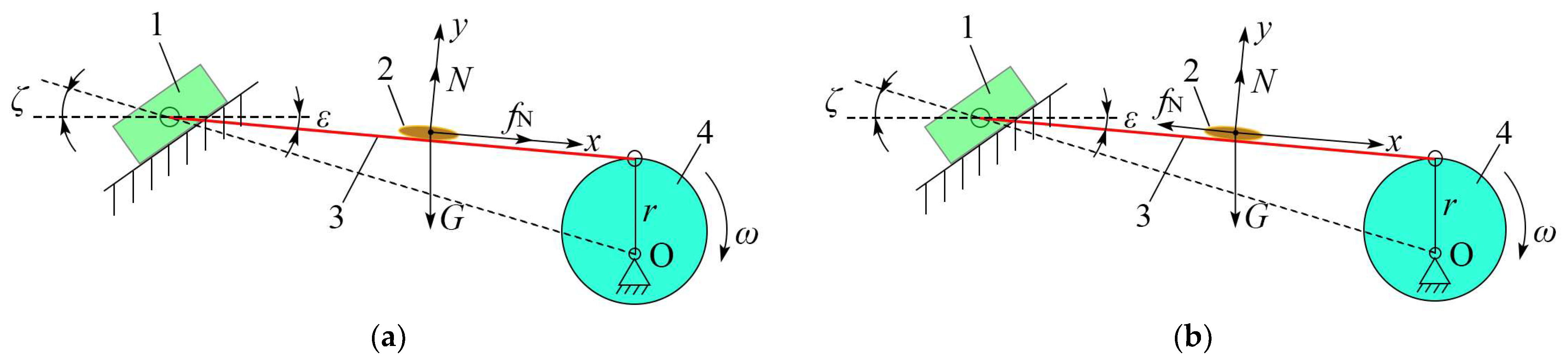
3.3.3. Determination of Movement Parameters

The vibrating screen has a certain horizontal and vertical motion driven by the eccentric bearing, which causes the material to slip and stratify on the screen surface to achieve the screening purpose. The main parameters that determine the movement of the debris on the screen surface are eccentric bearing speed n1, eccentric bearing eccentric distance r, screen surface inclination angle ε, screen surface swing direction angle ζ, and debris and screen surface friction angle η. To analyze the vibrating screen movement, the vibrating screen movement mechanism is simplified for kinematic analysis, the vibrating screen mechanism and kinematic analysis are shown in Figure 9.
The acceleration of the vibrating screen determines the form and direction of movement of the screen surface release, the acceleration of the vibrating screen should satisfy the following relationship:
a = r ω 2 cos ( ω t ) × 10 3
where a is the acceleration of the vibrating screen in m·s−2; ω is the angular velocity of the eccentric bearing in rad·s−1; t is the eccentric bearing rotation time in s.
When the flax of the material along the screen surface slides (Figure 9a), when cosωt = 1, the eccentric bearing angular velocity reaches the limit value of the material upward sliding. The limit speed of the eccentric bearing for material sliding upwards is:
n s = 30 π g sin ( η ε ) r cos ( η ε + ξ )
Similarly, when a > g sin ( ε + η ) cos ( ε + ξ + η ) , the flax of the material slides along the screen surface (Figure 9b), when cosωt = 1, the angular velocity of the eccentric bearing reaches the limit value of the material sliding upwards. The limit speed of the eccentric bearing for material sliding downwards is:
n x = 30 π g sin ( ε + η ) r cos ( ε + ξ + η )
When the flax of the material was thrown up, cosωt = 1, to obtain the material thrown up the eccentric bearing pole speed for:
n p = 30 π g cos ε r sin ( ε + ξ )
To ensure that the material slides upwards and downwards in the vibrating screen, and the downward sliding distance is greater than the upward sliding distance, there is a certain throwing up to meet the delamination of the offcuts, taking the acceleration ratio of the vibratory motion, i.e., the constant vibration index K 0 = r ω 2 g = 2.5 , the design screen inclination angle ε = 4°, the vibration direction angle ζ = 12°, and the friction angle η = 22° between the seeds and the screen surface. The best range of the eccentric bearing speed n of the vibrating screen is ns < n1 < np, and the lower the speed the worse the screening effect, and the higher the water content is the easier it is to cause blockage of the cleaning parts; the higher the speed, the more the machine vibrates and affects the operation of the machine. According to the actual working demand, we obtain the eccentric bearing speed 223 < n1 < 569, take the eccentric bearing eccentric distance r = 10 mm, and obtain the crank speed 477 r·min−1.

3.3.4. Determination of Wind Turbine Parameters

To ensure that the upper and lower sieve surfaces produce a uniform, stable airflow and reduce the rate of cleaning loss and the rate of impurities, the centrifugal fan is chosen to blow out the type of agricultural centrifugal fan (Figure 10). When the fan is working, the airflow is drawn in from both ends and blown out in the direction of the duct under the action of the blades.
The inclination and height of the fan outlet determine the windward area and influence the degree of separation of the debris [32], both of which satisfy the condition according to the geometric relationship [20]
H = k W sin θ
where H is the height of the air outlet in mm; k is the coefficient taken as 0.4; θ is the angle between the airflow and the screen surface, (°), taken as 30°.
To fully separate the offcuts and achieve the purpose of cleaning, the centrifugal fan air volume needs to meet:
Q s = Q γ η ρ
where Qs is the required air volume in m3/s; γ is the proportion of cleaned impurities to the fed volume, taken as 0.2; η is the mixing concentration ratio of the impurity airflow, taken as 0.25; ρ is the air density in kg·m−3, taken as 1.29 kg·m−3.
From Equations (14) and (15), the air outlet height is H = 240 mm, the outlet direction is adjustable and the air volume is Qs = 2.5 m3·s−1. When working, the full pressure of the centrifugal fan air pressure is calculated by the formula:
h = h j + h d h d = ρ V 1 2 / 2 g
where h is the full fan wind pressure in Pa; hj is the static pressure, overcoming the resistance of the air in the flow in Pa; hd is the dynamic pressure in Pa; V1 is the fan exit velocity in m·s−1; g is the acceleration of gravity in m·s−2, 9.8 m·s−2.
The required static pressure hj needs to be determined according to the working conditions, the fan in this study is a blow-out centrifugal fan, then the fan static pressure calculation formula is:
h j = κ l 1 ρ V 1 2 2 R L g + λ ρ V 1 2 2 g + μ ρ V 1 2 2 g
where κ is the airflow friction factor, take 0.35; l1 is the duct length in mm, 200 mm; RL is the duct hydraulic radius, take 0.1; λ is the duct resistance coefficient to airflow, take 0.35; μ is the fan inlet and outlet force coefficient to airflow, take 0.6.
To avoid seed loss, the airflow velocity in the wind screening area should be less than the maximum suspension velocity of flax 6.5 m·s−1, the airflow from the fan mouth out of the open area, the cleaning area gradually expanded, so the airflow velocity decreased, the screen area airflow velocity is about 60% to 70% of the airflow velocity at the outlet, so the airflow velocity at the outlet V1 = 9 m·s−1. Calculated by the Equations (16) and (17) Fan air pressure full pressure h = 14.13 Pa.
Centrifugal fan speed affects the quality of cleaning, the design of the fan impeller outside diameter D0 = 350 mm, and the number of blades for 4. The fan speed calculation formula is:
n 0 = 60 π D 0 h g ν ρ
where ν is the calculation coefficient, which is 0.35–0.40 and is taken as 0.4.
The calculation from Equation (18) provides the centrifugal fan speed n0 = 894 r·min−1.

4. Analysis of Tests and Results

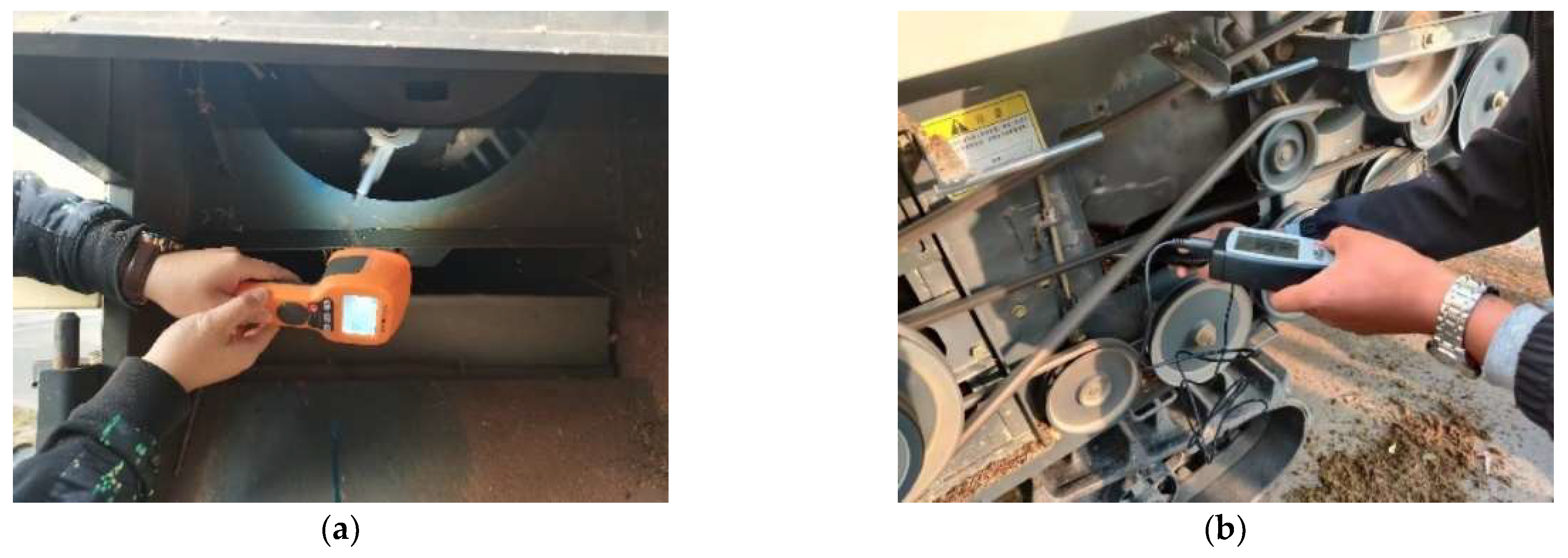
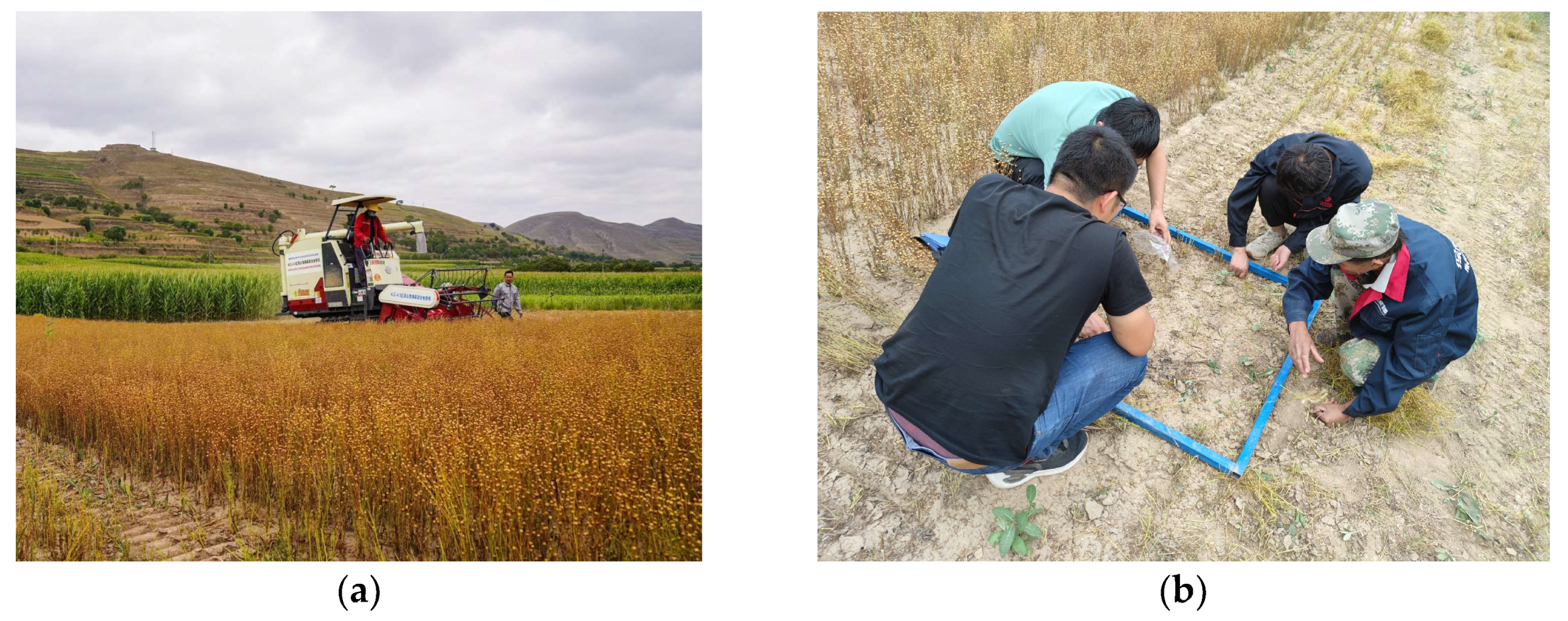
4.1. Test Site, Materials, Equipment

The field trial of the 4LZ-4.0 flax combine harvester was held from August 13 to 15, 2021, in Wencha Village, Laojun Town, Huining County, Baiyin City, Gansu Province, to verify the working performance and reliability of the design parameters. The test material was mature flax plants, the flax planting density was relatively uniform, with no collapse phenomenon, the test area was 0.17 hm2, the planted flax variety was Longya 14, the average plant height was 437.21 mm, the average number of flax capsules in a single plant was 6–11, the planting density was 689 plants·m−2, and the planting pattern was typical dryland dense flax planting. The test machine’s working parameters were set according to the working state of the test design, but in practice it was difficult to adjust the parameters precisely, so the parameters closest to the working state were used as the test machine’s working parameters during the test [33,34]. An LED stroboscope (SW-6500, 60–49,999 r·min−1, Guangzhou Suwei Electronic Instrument Co., LTD, Guangzhou, China.) was used to measure the speed of the threshing drum and the centrifugal fan, and a thermal anemometer (AR866A, 0.3–30 m·s−1, Dongguan Wanchuang Electronic Products Co., LTD. Dongguan, China.) was used to measure the airspeed at the outlet of the centrifugal fan. Figure 11 depict field tests.

4.2. Test Methods and Evaluation Indicators

The test was conducted by T/CAMA 30-2020 Full-feed flax combine harvester, GB/T 8097-2008 Harvesting machinery combine harvester test method, GB/T 6562-2008 Agricultural machinery test conditions, NY 2610-2014 Grain combine harvester safety operating procedures relevant standards and refer to GB/T 5982-2017 Threshing machine test methods and GB/T 2828.1-2012 Counting sampling test procedures. According to previous test results, the factors affecting the machine’s operating effectiveness were the advancing speed, threshing drum speed, and centrifugal fan speed, with the advancing speed being in the range of 0.5–1.5 m·s−1, the threshing drum speed being in the range of 600–800 r·min−1, and the centrifugal fan speed being in the range of 780–990 r·min−1. As a result, with the advancing speed (x1), threshing drum speed (x2), and centrifugal fan speed (x3) as independent variables and the threshing rate (Y1) and total loss rate (Y2) as response values, the test site was divided into 17 equal test areas of 25 m × 1.9 m in length × 1.9 m in width, using a three-factor, three-level response surface analysis method based on the Box–Behnken experimental design principle. An area of no less than 2 m was reserved at each end of the test area as an adjustment zone, and 17 sets of response surface analysis tests were implemented (Figure 12) with the fully harvested test area as the end single-test signal [35], and each test factor code as shown in Table 2. A small sample of no less than 1000 g of discharge from the grain outlet within the test trip was picked up at the end of the single test, and the mass of dropped flax seeds per square of the test area was randomly determined after the operation per the five-point sampling method, using clean sample bags for bagging and numbering for a total of five operations, with five squares taken each time as a source of test data, and measured using an electronic scale with an accuracy of 0.001 g after the completion of multiple operations, with the results averaged. The results of the response surface analysis tests are shown in Table 3.
Each test parameter is calculated as follows:
m t = m w + m j + m q + m f + m g Z p = m p m × 100 % Z z = m z m × 100 % S w = m w m × 100 % S j = m j m × 100 % S q = m q m × 100 % S f = m f m × 100 % S g = m g m × 100 % S t = S w + S j + S q
where mt is the total threshing mass in g; mw is the mass of unthreshed kernels in g; mj is the mass of entrained loss kernels in g; mq is the mass of scavenging loss in g; mf is the mass of splash loss kernels in g; mg is the mass of cutter loss kernels in g; mp is the mass of broken kernels in g; mz is the mass of impurities in kernels in g; Zp is the rate of broken kernels, %; Zz is the rate of impurities, %; Sw is the rate of unthreshed loss, %; Sj is the rate of entrained loss, %; Sq is the rate of scavenging loss, %; Sf is the rate of splash loss, %; Sg is the rate of cutter loss, %; and St is the total loss rate, %.

4.3. Analysis of Results

Design-Expert 10.0.0 software was applied for data processing and analysis. According to the experimental results in Table 3, the ANOVA [36,37] of the regression model was performed for the decontamination rate (Y1) and the loss rate (Y2), the results are shown in Table 4, and the quadratic regression models for Y1 and Y2 were obtained as follows:
Y1 = 95.42 + 1.72x1 + 4.74x2 + 0.68x3 − 0.82x1x2 + 1.66x1x3 + 0.82x2x3 − 0.33x12 − 2.22x22 − 1.4x32
Y2 = 4.09 − 1.59x1 − 0.35x2 + 0.88x3 − 1.74x1x2 + 0.24x2x3 + 0.36x12 + 1.06x22 − 0.12x32
According to the analysis of variance of the regression equation, the quadratic regression model of the stripping rate p < 0.0001 indicates that the regression model is extremely significant; the misfit term p > 0.05 indicates that the misfit is not significant, indicating that the quadratic regression equation fitted by the model is consistent with reality and can correctly reflect the relationship between the stripping rate (Y1) and the advancing speed (x1), drum speed (x2) and centrifugal fan speed (x3). The primary terms x1, x2, and x1x3 are highly significant, the secondary term x22 is highly significant, the primary term x3 is significant, the secondary term x32 is significant and the other terms are not significant. Based on the magnitude of the regression coefficients for each factor of the model, the primary and secondary order of influence of each factor on the threshing rate was obtained as x2, x1, and x3, i.e., threshing drum speed, advancing speed, and centrifugal fan speed. Similarly, the total loss rate regression model was highly significant and the misfit was not significant, indicating that the quadratic regression equation fitted by the model was consistent with reality. Based on the magnitude of the regression coefficients for each factor of the model, the main order of influence of each factor on the threshing rate was obtained as x1, x3, and x2, i.e., advancing speed, centrifugal fan speed, and threshing drum speed.

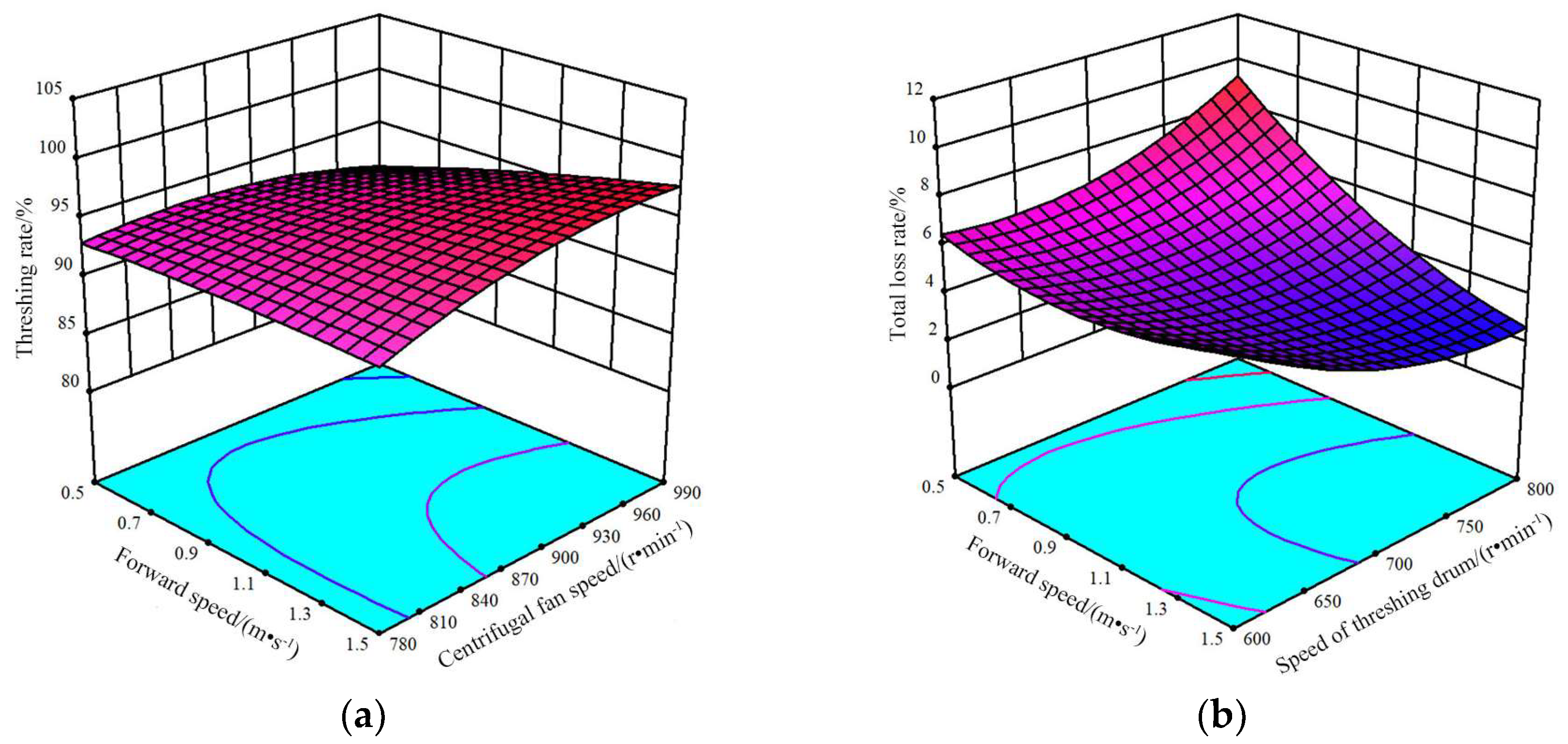
4.4. Analysis of Model Interaction Items

According to the quadratic regression model of each response value obtained from the experiment, the response surface plots of different interaction levels of three factors, namely advancing speed, threshing drum speed, and centrifugal fan speed, were made on the rate of threshing and total loss, and the response surface between each factor was made by the regression model Equations (19) and (20), respectively (Figure 13).
As can be seen from Figure 13, the interaction of advancing speed and centrifugal fan speed has an extremely significant effect on the threshing rate. The reason for this is that as the speed of the threshing drum increases so that the caraway capsule is completely broken, the advancing speed increases so that the feed volume increases, and the speed of the centrifugal fan directly determines how much of the flax seed is blown out, making the number of flax seeds that are not removed vary considerably. When the threshing drum speed is 700 r·min−1, the advancing speed increases from 0.5 m·s−1 to 1.5 m·s−1, and the net rate increases mainly because the advancing speed increases the feeding volume, the feeding volume increases so that the threshing gap can be filled with flax plants, the threshing effect is more adequate, making the net rate increase. When the threshing drum speed is 700 r·min−1, the centrifugal fan speed is from 780 r·min−1 to 990 r·min−1, and the threshing rate gradually increases, mainly because the centrifugal fan speed is smaller when the air volume is smaller, which cannot be flax threshing material for stratification, resulting in some incomplete threshing capsules and seeds by the vibrating screen out of the machine, making the threshing rate very low. When the centrifugal fan speed is higher, the air volume is larger, so that the flax off-growth begins to stratify, the off-growth is entrained in the discharge of flax seeds and threshing of incomplete capsules, making the net rate gradually increase.
When the centrifugal fan speed is 885 r·min-1, the advancing speed increases from 0.5 m·s−1 to 1.5 m·s−1, the total loss is reduced first and then increased, mainly because when the advancing speed is small, the paddle wheel continuously fights the flax capsules, making the flax cutting table fall causing grain loss, resulting in a larger total loss rate; when the advancing speed is larger, the speed ratio of the paddle wheel speed and advancing speed affects the work of the cutting table, causing part of the flax plant to be cut without being supported by the paddle wheel, resulting in part of the flax plant not entering the cutting table smoothly, resulting in a large loss of cutting table. At the same time, when the advancing speed is higher, the combine feeds more, resulting in more threshing material, and the centrifugal fan cannot effectively stratify the threshing material for cleaning, resulting in entrained losses, making the total loss rate larger. When the centrifugal fan speed is 885 r·min−1, the threshing drum speed increases from 600 r·min−1 to 800 r·min−1, and the total loss rate gradually increases, mainly because the increase in threshing drum speed makes the threshing material more fully threshed, the centrifugal fan is subject to increased workload, part of the threshing material cannot be effectively stratified, making part of the threshing material entrained and discharged, resulting in scavenging losses, making the total loss rate gradually increase.

4.5. Optimal Working Parameters Determination and Experimental Verification

According to the quadratic regression model results and response surface analysis, to further improve the operational performance of the flax combine harvester, considering the boundary conditions of each factor, and according to the flax operational quality requirements and the actual operation, the full-factor quadratic regression equation of performance indicators was established [18,19], and the objective optimization and optimal working parameters were determined with the objective function and constraints as:
max G ( x ) = Y 1 ( x 1 , x 2 , x 3 ) min G ( x ) = Y 2 ( x 1 , x 2 , x 3 )
1 x 1 1 1 x 2 1 1 x 3 1
The optimization solver in Design-Expert 10.0.0 software was used to solve the regression Equations model (19) and (20) under objective (21), and the final optimization test indexes were 98.4% threshing rate and 2.65% total loss rate. The optimum operating parameters were: an advancing speed of 1.5 m·s−1, a threshing drum speed of 788.49 r·min−1, and a centrifugal fan speed of 885.34 r·min−1.
To verify the reliability of the regression Equations models (19) and (20), the optimal working parameters were optimized and the flax combine harvester was subjected to several operational performance tests, and the values of the combined optimized parameters were rounded to an advancing speed of 1.5 m·s−1, a threshing drum speed of 780 r·min−1 and a centrifugal fan speed of 885 r·min−1, taking into account the convenience of measurement and testing. Under the same test conditions (refer to Section 3.1 and Section 3.2), the test was repeated five times and the results were averaged and shown in Table 5, proving that the machine meets the requirements of flax harvesting. The machine was certified by a third-party testing body, which is conducive to achieving integrated support for flax production operations in China and reducing labor input.

5. Discussions

(1)
This study aims at the current status of China’s linen plants and the conditions and planting models of the planting in the hills and mountains in Gansu Province. After the optimization design of key links such as linen harvesting, transportation, degranulation, and clear selection, the linseed harvester can meet the current joint harvesting requirements of linen seed seeds in Gansu Province. Compared with existing flax combine harvesters, the machine is suitable for mechanized combined harvesting of flax in hilly areas, filling the gap in China’s hilly areas where flax cannot be mechanized for combined harvesting, and can solve the problem that existing large combine harvesters cannot carry out hilly area operations. At the same time, the harvesting efficiency of this machine can reach 0.5 hm2·h−1, and one person can only harvest 0.06 hm2 a day. The flax harvest has a significant impact on the economy of linen planting, which is consistent with the research conclusions of Dai et al. [20] and Souček, J et al. [8]. Similarly, the optimized design of the hilly areas and linen combined harvester can achieve an efficient harvest of linen, which is improves the operating performance of the machine compared with the large linen combined harvesting machine [20].
(2)
Trials found that different flax varieties have different plant heights and stem moisture content, which has a certain impact on the mechanization of the combined effect of harvesting. Špokas L. et al. [38] showed that the stand lodging rate and water content of crops before harvest have a great influence on grain loss after threshing and cleaning by combine harvesters. Based on the research results obtained, it can be stated that the increase in the clearance between shutters of the upper sieve from 9 mm to 14 mm allows for a decrease in grain losses behind the straw walker and cleaning mechanism by 0.13% in the case of wheat and by 0.24% in case of barley. By the same token, when operating on an inclined field, the flaxseed, and offcuts inside the cleaning system were affected by gravity, resulting in an uneven distribution of flaxseed and offcuts on the screen surface of the vibrating sieve, with offcuts piling up on the screen surface and poor cleaning results. Therefore, this study continues to investigate the relationship between the combine’s walking posture and the flax plant.
(3)
China made a breakthrough in the mechanized harvesting of flax, but the degree of mechanization is very low compared with wheat, rice, and other staple crops, and the existing rice and wheat combine harvesters in the current market cannot adapt to the mechanized combined harvesting of flax, and the specialized foreign flax harvesters are less utilized, expensive, unacceptable to farmers, and not suitable for the mechanized harvesting of flax in China. The crawler-type flax combine harvester designed in this study improves harvesting efficiency, saves labor costs, and reduces labor intensity. The key components of the flax combine designed in this study can be sold as accessories and installed on common rice and wheat combines to enhance the practicality and utilization of the machine, which can increase the marketability of the machine.

6. Conclusions

(1)
In this study, the self-propelled flax combine harvester was optimized through mechanism design and theoretical calculations for the conditions and planting patterns of flax field cultivation and hilly cultivation in China and Gansu Province. The machine was adapted to the combined harvesting operation of flax in the irrigation area of Hexi and the hilly area of Loess Plateau, and the operation effect meets the combined harvesting requirements of flax.
(2)
By the Box–Behnken experimental design, 17 sets of response surface analysis experiments were carried out with advancing speed (x1), threshing drum speed (x2), and centrifugal fan speed (x3) as independent variables, and threshing rate (Y1) and total loss rate (Y2) as response values, using a three-factor, three-level response surface analysis method. The order of influence of the three factors on the threshing rate was threshing drum speed, advancing speed, and centrifugal fan speed, while the order of influence on the total loss rate was advancing speed, centrifugal fan speed, and threshing drum speed.
(3)
The test results showed that under a typical dryland dense flax cultivation pattern, the test machine had a 97.46% netting rate and a 2.99% total loss rate according to the test design criteria. The total loss rate was 2.99%. This shows that the optimization of the working parameters can reduce the losses in the process of mechanized flax harvesting and improve the harvesting efficiency, and the operational effect can meet the market requirements of flax harvesting.

Author Contributions

Conceptualization, W.Z. and R.S.; methodology, W.Z. and F.D.; software, T.W. and Y.Z.; validation, X.L., T.W. and Y.Z.; formal analysis, X.L.; investigation, W.Z. and F.D.; writing—original draft preparation, R.S.; writing—review and editing, R.S. and W.Z.; visualization, R.S.; supervision, W.Z.; project administration, W.Z. and F.D. All authors have read and agreed to the published version of the manuscript.

Funding

This research was supported by the earmarked fund for China Agriculture Research System (CARS)(Grant NO. CARS-14-1-28), Key R&D Program of Gansu Province in China (Grant NO. 20YF3WA019) and Gansu Province Science and Technology Plan Major Special Project (Grant NO. 21ZD4NA022-05).

Institutional Review Board Statement

Not applicable.

Data Availability Statement

The data presented in this study are available on request from the authors.

Acknowledgments

The authors thank the editor for providing helpful suggestions for improving the quality of this manuscript.

Conflicts of Interest

The authors declare no conflict of interest.

References

  1. Sydow, Z.; Idaszewska, N.; Janeba-Bartoszewicz, E.; Bieńczak, K. The Influence of Pressing Temperature and storage conditions on the quality of the linseed oil obtained from Linum Usitatissimum L. J. Nat. Fibers 2021, 18, 442–451. [Google Scholar] [CrossRef]
  2. Depuydt, D.; Hendrickx, K.; Biesmans, W.; Ivens, J.; Van Vuure, A.W. Digital image correlation as a strain measurement technique for fibre tensile tests. Compos. Part Appl. Sci. Manuf. 2017, 99, 76–83. [Google Scholar] [CrossRef]
  3. Habibi, M.; Laperrière, L.; Lebrun, G.; Toubal, L. Combining short flax fiber mats and unidirectional flax yarns for composite applications: Effect of short flax fibers on biaxial mechanical properties and damage behaviour. Compos. Part B Eng. 2017, 123, 165–178. [Google Scholar] [CrossRef]
  4. Shi, R.J.; Dai, F.; Zhao, W.Y.; Liao, X.L.; Qu, J.F.; Zhang, F.W. Optimization and experiment of operation parameters of hilly area flax combine harvester. J. Jilin Univ. (Eng. Technol. Ed.) 2022, 52, 2746–2755. [Google Scholar]
  5. Song, X.F.; Dai, F.; Shi, R.J.; Wang, F.; Zhang, F.W.; Zhao, W.Y. Simulation and experiment of the vibration separation of flax threshing material using non-spherical particles model. Trans. CSAE. 2022, 38, 39–46. [Google Scholar]
  6. Dai, F.; Zhao, W.Y.; Shi, R.J.; Zhao, Y.M.; Zhang, F.W.; Liu, X.L.; Zhang, S.L. Research progress analysis of key technology and equipment for mechanized harvest of flax. Chin. J. Oil Crop Sci. 2022, 44, 1148–1158. [Google Scholar]
  7. Mańkowski, J.; Maksymiuk, W.; Spychalski, G.; Kołodziej, J.; Kubacki, A.; Kupka, D.; Pudełko, K. Simulation and experiment of the vibration separation of flax threshing material using non-spherical particles model. J. Nat. Fibers 2018, 15, 53–61. [Google Scholar] [CrossRef]
  8. Souček, J.; Šturc, T.; Mareček, J. Analysis of linseed production with use of flax puller and combine harvester for its harvest. Acta Univ. Agric. Silvic. Mendel. Brun. 2017, 65, 511–517. [Google Scholar] [CrossRef] [Green Version]
  9. Song, H. Flax(til) Sheller of 5TF-45 Type Design and Research; Shanxi Agricultural University: Jinzhong, China, 2016. [Google Scholar]
  10. Wang, J.Z. Development and test of 5TS-50 type half complex multipurpose minor crop thresher. J. Agric. Mech. Res. 2013, 35, 127–130, 134. [Google Scholar]
  11. Gao, T.N. Research on semi-repeat threshing machinery for small seed flax crops. Farm Mach. 2011, 25, 100–102. [Google Scholar]
  12. Zhao, W.C.; Zhang, Y.Y.; Gong, Y.F.; Wang, Z.Y. Design and parameter optimisation of the threshing mechanism of a self-propelled flax threshing and spreading machine. Agric. Mach. Using Maint. 2020, 2, 1–3. [Google Scholar]
  13. Liu, Y.X.; Dai, F.; Zhao, W.Y.; Shi, R.J.; Zhang, S.L.; Wei, W.C. Design and experiment of handheld flax windrower. J. Chin. Agric. Mech. 2019, 40, 26–29. [Google Scholar]
  14. Shi, R.J.; Dai, F.; Zhao, W.Y.; Liu, Y.X.; Zhang, S.L.; Wei, W.C. Biomechanical properties test of flax stem. J. Chin. Agric. Mech. 2018, 39, 45–50. [Google Scholar]
  15. Qu, J.F.; Zhao, W.Y.; Zhao, Y.M.; Dai, F.; Shi, R.J.; Li, Y.J.; Fu, Q.F.; Li, Y.W. Design and experiment of full feed flax threshing and cleaning machine. Acta Agric. Zhejiangensis 2022, 34, 831–840. [Google Scholar]
  16. Shi, R.J.; Dai, F.; Zhao, W.Y.; Zhang, S.L.; Zhang, F.W.; Liu, X.L. Design and test of full-feed flax thresher. J. China Agric. Univ. 2019, 24, 120–132. [Google Scholar]
  17. Dai, F.; Zhao, W.Y.; Liu, G.C.; Zhang, S.L.; Shi, R.J.; Wei, B. Design and experiment of separating and cleaning machine for flax threshing material. Trans. Chin. Soc. Agric. Mach. 2019, 50, 140–147. [Google Scholar]
  18. Dai, F.; Fu, Q.F.; Zhao, W.Y.; Shi, R.J.; Song, X.F.; Zhang, S.L. Design and test of double duct system of air-screen separating and cleaning machine for flax threshing material. Trans. Chin. Soc. Agric. Mach. 2021, 52, 117–125. [Google Scholar]
  19. Shi, L.R.; Ma, Z.T.; Zhao, W.Y.; Yang, X.P.; Sun, B.G.; Zhang, J.P. Calibration of simulation parameters of flaxed seeds using discrete element method and verification of seed-metering test. Trans. CSAE 2019, 35, 25–33. [Google Scholar]
  20. Dai, F.; Zhao, W.Y.; Shi, R.J.; Liu, X.L.; Cui, Y.S.; Fu, S.N. Design and experiment on self-propelled flax combine harvester. Chin. J. Oil Crop Sci. 2022, 44, 678–686. [Google Scholar]
  21. Shi, R.J.; Dai, F.; Liu, X.L.; Zhao, W.Y.; Qu, J.F.; Zhang, F.W.; Qin, D.G. Design and experiments of crawler-type hilly and mountaineous flax combine harvester. Trans. CSAE 2021, 37, 59–67. [Google Scholar]
  22. Liao, Q.X.; Xu, Y.; Yuan, J.C.; Wan, X.Y.; Jiang, Y.J. Design and experiment on combined cutting and throwing longitudinal axial Flow threshing and separating device of rape combine harvester. Trans. Chin. Soc. Agric. Mach. 2019, 50, 140–150. [Google Scholar]
  23. Wang, W.Z.; Liu, W.R.; Yuan, L.H.; Qu, Z.; He, X.; Lv, Y.L. Simulation and experiment of single longitudinal axial material movement and establishment of wheat plants model. Trans. Chin. Soc. Agric. Mach. 2020, 51 (Suppl. S2), 170–180. [Google Scholar]
  24. Wu, J.; Tang, Q.; Mu, S.L.; Jiang, L.; Hu, Z.C. Test and optimization of oilseed rape (Brassica napus L.) threshing device based on DEM. Agriculture 2022, 12, 1580. [Google Scholar] [CrossRef]
  25. Di, Z.F.; Cui, Z.K.; Zhang, H.; Zhou, J.; Zhang, M.Y.; Bu, L.X. Design and experiment of rasp bar and nail tooth combined axial flow corn threshing cylinder. Trans. CSAE 2018, 34, 28–34. [Google Scholar]
  26. Li, Y.; Xu, L.Z.; Lv, L.Y.; Shi, Y.; Yu, X. Study on modeling method of a multi-parameter control system for threshing and cleaning devices in the grain combine harvester. Agriculture 2022, 12, 1483. [Google Scholar] [CrossRef]
  27. Shi, R.J.; Dai, F.; Zhao, W.Y.; Zhang, F.W.; Shi, L.R.; Guo, J.H. Establishment of discrete element flexible model and verification of contact parameters of flax stem. Trans. Chin. Soc. Agric. Mach. 2022, 53, 146–155. [Google Scholar]
  28. Tian, L.Q.; Li, H.Y.; Hu, H.D.; Chen, L.B.; Xiong, Y.S.; Jin, R.D. Design and experiment on coaxial double speed threshing for combine harvester. Trans. Chin. Soc. Agric. Mach. 2020, 51 (Suppl. S2), 139–146. [Google Scholar]
  29. Xu, L.Z.; Li, Y.; Chai, X.Y.; Wang, G.M.; Liang, Z.W.; Li, Y.M.; Li, B.J. Numerical simulation of gas–solid two-phase flow to predict the cleaning performance of rice combine harvesters. Biosyst. Eng. 2020, 190, 11–24. [Google Scholar] [CrossRef]
  30. Badretdinov, I.; Mudarisov, S.; Lukmanov, R.; Permyakov, V.; Ibragimov, R.; Nasyrov, R. Mathematical modeling and research of the work of the grain combine harvester cleaning system. Comput. Electron. Agric. 2019, 165, 104966. [Google Scholar] [CrossRef]
  31. Wang, B.K.; Yu, Z.Y.; Hu, Z.C.; Cao, M.Z.; Zhang, P.; Wang, B. Numerical simulation and experiment of flow field in three air systems of air separation system of peanut pickup harvester. Trans. Chin. Soc. Agric. Mach. 2021, 52, 103–114. [Google Scholar]
  32. Liang, Z.W.; Xu, L.Z.; De Baerdemaeker, J.; Li, Y.M.; Saeys, W. Optimisation of a multi-duct cleaning device for rice combine harvesters utilising CFD and experiments. Biosyst. Eng. 2020, 190, 25–40. [Google Scholar] [CrossRef]
  33. Zhang, J.F.; Cao, G.Q.; Jin, Y.; Tong, W.Y.; Zhao, Y.; Song, Z.Y. Parameter optimization and testing of a self-propelled combine cabbage harvester. Agriculture 2022, 12, 1610. [Google Scholar] [CrossRef]
  34. Song, Y.L.; Zhang, X.H.; Wang, W. Rollover dynamics modelling and analysis of self-propelled combine harvester. Biosyst. Eng. 2021, 209, 271–281. [Google Scholar] [CrossRef]
  35. Tian, L.Q.; Lin, X.; Xiong, Y.S.; Ding, Z. Design and performance test on segmented-differential threshing and separating unit for head-feed combine harvester. Food Sci. Nutr. 2021, 9, 2531–2540. [Google Scholar] [CrossRef]
  36. Shahmaleki, M.; Beigmohammadi, F.; Movahedi, F. Cellulose-reinforced starch biocomposite: Optimization of the effects of filler and various plasticizers using Design-Expert method. Starch-Stärke 2020, 73, 2000028. [Google Scholar] [CrossRef]
  37. Pavan, K.R.S.; Raveendra, R.J. Development and validation of stability-indicating-HPLC method for the determination of related substances in novel nitroimidazole antituberculosis drug pretomanid: Robustness study by Design-Expert and application to stability studies. Biomed. Chromatogr. 2022, 36, e5498. [Google Scholar]
  38. Špokas, L.; Adamčuk, V.; Bulgakov, V.; Nozdrovický, L. The experimental research of combine harvesters. Res. Agr. Eng. 2016, 62, 106–112. [Google Scholar] [CrossRef]
Figure 1. Flax plant structure and cultivation status: (a) flax plant structure; (b) status of flax cultivation, A: Flax capsule; B: Flax stem.
Agriculture 13 00229 g001
Figure 2. The 4LZ-4.0 flax combine structure schematic and prototype diagram: (a) Schematic diagram of the structure; (b) prototype drawing. (1) Awning. (2) Operating lever. (3) Driver’s platform. (4) Over-bridge. (5) Wheel spreader. (6) Wheel paddle. (7) Splitter. (8) Blade guard. (9) Cutting knife. (10) Guard. (11) Header. (12) Hydraulic cylinder. (13) Driving wheel. (14) Support wheel. (15) Track. (16) Tensioning wheel. (17) Chassis. (18) Oil tank. (19) Shredder. (20) Threshing drum. (21) Grain discharge cylinder.
Agriculture 13 00229 g002
Figure 3. Diagram of the churn winding and anti-winding device: (a) Churning dragon wrap. (b) Diagram of the anti-tangle device. (1) Churning dragon wrap. (2) Diagram of the anti-tangle device. (3) Stirrer. (4) Anti-winding plate. Note: L is the length of the churn in mm. Lf is the length of the anti-winding plate in mm. L1 is the diameter of the churn in mm. L2 is the long shaft of the anti-winding churn in mm.
Agriculture 13 00229 g003
Figure 4. Switching diagram of a combination of decide granular device structure: (1) Enter the gearbox of the drum power in the drum. (2) Removing the barrel with the barrel. (3) Persia roller lid. (4) Combined moldy granular drum. (5) Grass guide. (6) Narrow grille concave board. (7) Welding in a departure drum.
Agriculture 13 00229 g004
Figure 5. Force analysis of screw feed head and flax stem: Note: f is the frictional force between the flax plant and the spiral blade, N; T is the normal thrust, N; F is the combined frictional and thrust force, N; ω is the angular speed of the threshing drum in rad·s−1; D is the diameter of the threshing drum in mm; d1 is the diameter of the small end of the spiral feeding head in mm; d2 is the diameter of the large end of the spiral feeding head in mm; L3 is the length of the spiral feeding head in mm; β is the angle of friction between the threshing material and the spiral blade, (°); α is the angle of lift of the spiral blade, (°).
Agriculture 13 00229 g005
Figure 6. Schematic diagrams of the combined longitudinal axial flow threshing drum with ribs-rod teeth: (1) Screw feed head. (2) Striker threshing element. (3) Spoke disc. (4) Crossbar. (5) Rod tooth threshing element. Note: L4 is the length of the striker section in mm; L5 is the length of the separating section in mm; L6 is the length of the grass discharge section in mm; L7 is the working length of the rod teeth in mm; L8 is the distance between the rod teeth in mm.
Agriculture 13 00229 g006
Figure 7. Schematic diagram of the structure of the narrow grid recess: (a) Concave plate size. (b) Concave plate-clad corners. (1) Narrow grating concave sieve. (2) Grating bars. (3) Horizontal spacer. Note: ds is the spacing between the grating bars in mm; dh is the spacing between the horizontal dividers in mm; dt is the gap between the concave plates in mm.
Agriculture 13 00229 g007
Figure 8. Schematic diagrams of the structure of the combined cleaning unit: (1) Centrifugal wind machine power input belt. (2) Centrifugal divider. (3) Wind guide. (4) Primary seed screw conveyor. (5) Woven sieve. (6) Seed skid. (7) Secondary miscellaneous residual screw conveyor. (8) Eccentric bearing. (9) Vibrating screen power input pulley. (10) Tail sieve. (11) Fish scale sieve. (12) Fish scale sieve fixed plate. (13) Fish scale sieve opening adjustment device. (14) Shaking plate. (15) Vibrating screen housing.
Agriculture 13 00229 g008
Figure 9. Kinematic model of a vibrating screen: (a) Slip-on detachment. (b) Slippage of debris. (1) limit slider. (2) Flaxseed grain. (3) Sieve surface. (4) Eccentric wheel. Note: G is the gravity of the flaxseed grain, N; N is the support force on the flaxseed grain, N; Fn is the friction force on the sieve surface on the flaxseed grain, N; ω is the angular speed of the eccentric bearing in rad·s−1.
Agriculture 13 00229 g009
Figure 10. Schematic diagrams of the centrifugal fan structure: (1) Centrifugal fan power input pulley. (2) Fan blade. (3) Centrifugal fan power output pulley. Note: D0 is the diameter of the centrifugal fan in mm; A0 is the width of the centrifugal fan blade in mm; W0 is the height of the centrifugal fan blade in mm.
Agriculture 13 00229 g010
Figure 11. Determination of threshing drum speed and centrifugal fan airspeed on the prototype: (a) Threshing drum speed determination. (b) Centrifugal fan outlet air velocity determination.
Agriculture 13 00229 g011
Figure 12. Field test: (a) Field operation of the tester apparatus. (b) Field testing of operational effectiveness.
Agriculture 13 00229 g012
Figure 13. Influence of interaction factors on response values: (a) Effect of advancing speed and centrifugal fan speed on decontamination rate. (b) Effect of advancing speed and threshing drum speed on total loss rate.
Agriculture 13 00229 g013
Table 1. Technical parameters of 4LZ-4.0 flax combine harvester.
ParametersValue
Structural formsFull-feed crawler
Overall machine dimensions (L × W × H)/mm4950 × 2150 × 2590
Width of cutting table/mm1900
Feeding capacity/(kg·s−1)4.0
Operating speed/(m·s−1)0.75–1.5
Productivity/(hm2·h−1)0–0.5
Rated power/kW51.5
Rated speed/(r·min−1)2400
Chain harrow typeChain rake type
Threshing drum parameters (diameter × length)/mm550 × 1350
Track pitch × number of knots × width/mm90 × 44 × 400
Track gauge/mm1080
Ground clearance/mm320
Table 2. Factor-level coding table.
LevelsTest Factors
Advancing Speed/(m·s−1)Threshing Drum Speed/(r·min−1)Centrifugal Fan Speed/(r·min−1)
−10.5600780
01700885
11.5800990
Table 3. Test scheme and its results.
Test No.x1x2x3Y1/%Y2/%
100095.034.09
200095.084.06
3−1−1085.876.55
410197.534.5
511098.232.63
600096.944.07
700095.054.02
80−1−186.74.88
9−11096.019.32
1001−195.513.48
1110−192.882.43
1200095.024.21
13−10−193.186.05
140−1186.466.1
15−10191.187.14
161−1091.396.18
1701198.556.13
1300095.034.09
Table 4. Variance analysis of the regression coefficients.
Test IndexSources of VarianceRegression CoefficientsVariance SumDegree of FreedomFp
Threshing rateModel254.95928.3338.46<0.0001 **
x123.77123.7732.270.0007 **
x2179.361179.36243.53<0.0001 **
x33.7113.715.040.0596
x1x22.7212.723.700.0960
x1x311.06111.0615.010.0061 **
x2x32.6912.693.650.0976
x120.4610.460.630.4550
x2220.72120.7228.130.0011 **
x328.2618.2611.220.0123 *
Residual error5.1670.74
Lack-of-fit2.2830.761.060.4597
Error2.8740.72
Sum260.1116
Total loss rateModel51.2595.69455.97<0.0001 **
x120.13120.131611.74<0.0001 **
x20.9710.9777.35<0.0001 **
x36.1816.18494.63<0.0001 **
x1x212.08112.08966.88<0.0001 **
x1x30.2410.2419.220.0032 **
x2x30.5110.5140.930.0004 **
x124.7314.73378.80<0.0001 **
x225.8415.84467.43<0.0001 **
x320.06110.0614.850.0634
Residual error0.08770.012
Lack-of-fit0.06730.0224.330.0955
Error0.02145.150 × 10−3 to × 10−3
Sum51.3416
Note: ** means very significant (p < 0.01); * means significant (0.01 < p < 0.05).
Table 5. Verify test results.
Test IndicatorsThreshing Rate/%Contamination Rate/%Breakage Rate/%Cutter Loss Rate/%Entrainment Loss Rate/%Cleaning Loss Rate/%Splash Loss Rate/%Total Loss Rate/%
Standard values≥95≤5≤3≤3≤3≤3≤3≤5
Test results97.463.910.091.430.261.090.212.99
Disclaimer/Publisher’s Note: The statements, opinions and data contained in all publications are solely those of the individual author(s) and contributor(s) and not of MDPI and/or the editor(s). MDPI and/or the editor(s) disclaim responsibility for any injury to people or property resulting from any ideas, methods, instructions or products referred to in the content.

