1. Introduction
The destruction of the environment and ecosystems by conventional farming methods has been worsening in recent years, and questions have been raised regarding the sustainability of the primary industry and food production in terms of maintaining material and energy resources, human health, and ecosystem health [
1]. Therefore, a farming method called Synecoculture
TM [
2], which aims to break away from the trade-off between productivity and environmental destruction, has garnered attention. This farming method does not involve any tillage, fertilization, or spraying of agrochemicals; instead, it achieves food production by constructing an augmented ecosystem with highly enhanced biodiversity. Multiple species of plants and fruit trees with varying growth rates are mixed and grown densely; therefore, sowing, pruning of dominant plants, and harvesting tasks should be performed at all times. Furthermore, cultivation in half-shaded conditions is recommended to prevent grounds from drying out and harbor the coexistence of multiple crops. Meanwhile, even though solar power generation is becoming widespread to overcome the problems of energy shortages, the space under solar panels in solar power plants remains unutilized, and it is believed that conducting Synecoculture by utilizing this space would be effective. Developing an augmented ecosystem with Synecoculture is advantageous to producing food even in dry lands where conventional agriculture is not suitable. At the same time, since many types of crops are densely mixed in Synecoculture, it is difficult to handle the sowing, pruning, and harvesting with existing agricultural machinery. Manual work is basically required for the practical management of Synecoculture, which becomes highly time- and labor-intensive as the scale expands. Most existing agricultural robots have focused on the automation of a single task in simplified monoculture production, and none of them have realized the above three tasks as a unified system working in the complex vegetation. Moreover, contact with and damage to plants in the vicinity of the target area can lead to poor growth and a decrease in the value of the harvested product. Thus, unnecessary contact with plants other than the work target should be avoided as much as possible. Because performing multiple tasks in a dense plant environment requires recognition of the environment at various points, autonomous recognition of the environment and sensitive operation of the robot are the major issues to resolve. Therefore, we aimed to develop a robot that has the power and functions to perform various tasks while having a small and flexible structure that reduces contact with the environment.
In this paper, we presented a new robot for the management of Synecoculture compatible with the complex vegetation and spatial constraint under solar panels. We developed a mechanism that was capable of movement where there were no paved road surfaces and could perform the three tasks of sowing, pruning, and harvesting in a Synecoculture farmland environment where varieties of plants were densely mixed. We specifically developed a four-wheel-drive gate-type mobile robot equipped with an XY table that could move in the horizontal direction, passing under solar panels and straddling the ridges. We then developed a robotic arm attached to a gate-type mobile robot that could avoid obstacles on the ground within certain height limits by expanding and contracting. We also developed a mechanism for sowing individual seeds coated in the soil as a “seed ball”, a pruning and harvesting mechanism that griped and cut the harvest. Moreover, an operation system of the robot to conduct the three tasks was also developed. An integrated controller by implementing tool coordinate-based operating, automatic sowing, and task switching via a menu interface were implemented. The system employed a 360° camera in equirectangular format as the tool’s viewpoint, enabling wide-area recognition of the environment surrounding the tool.
The two main contributions of this study are as follows. First, we developed a robot that could perform multiple tasks to implement a special farming method called Synecoculture. Most of the existing studies have only performed harvesting tasks for a single species, but if the robot can perform multiple tasks, it will be possible to automate the practices of complex farming, such as Synecoculture, using mainly the robot. However, simply combining robotic mechanisms specific to each task will increase the size of the robot, which will increase its costs and undesirable contacts with other plants. Therefore, our main contribution was to establish a simple unified mechanism to go beyond the trade-off between multi-functionality and robot size. In particular, for seed planting, we utilized the seed ball method in order to treat multiple sizes and shapes of seeds. By placing a single seed instead of multiple seeds in a single ball, we were able to simplify the sowing mechanism, because different seeds could be operated in a unified way.
Second, we proposed an operation system that facilitated the operation of the robot in complex farming environments. Existing agricultural robots mainly aimed at automation to save manpower in monoculture environment, but mixed polyculture situations subject to this study were too complex to fully automate. In particular, automatic recognition of the environment and work objects that coexisted with a large number of plants in close proximity was the technical burden. Therefore, we proposed the human-operated control as the previous stage of automation and developed an easy-to-operate controller. We proposed an effective user interface that provided sufficient visibility even in dense vegetation, which was revealed to be effective in performing the tasks. The control system could be applied to other existing farming methods which would enable remote-operated farming. As experience with operational results is accumulated over multiple situations, it will be possible to automate the processes.
2. Materials and Methods
2.1. Relevant Research
Existing agricultural robots include those by FarmBot [
3], which move on rails installed in the field and perform multiple tasks by exchanging tools; or by Thorvald II [
4], which move through fields with tires to perform work. However, most agricultural robots were designed for conventional farming methods with regular arrangements. Even among agricultural robots that are supposed to run on rough terrain and perform a single task [
5], there are no examples of agricultural robots yet that could perform several complex tasks such as sowing, pruning, and harvesting in a mixed and dense environment of plants such as that of Synecoculture. Most studies have been on harvesting [
6,
7,
8,
9,
10,
11,
12,
13]. Jun et al. proposed a robot that recognized tomatoes by image analysis and automatically harvested them [
14]. Arad et al. proposed a sweet pepper harvesting robot in the green house [
15]. Megalingam et al. proposed an unmanned robotic coconut tree climber and harvester [
16]. A number of grippers have also been proposed for efficient harvesting [
17,
18,
19].
Many studies verified the application of robots using simple plants produced in the laboratory; however, trials are beginning to be conducted in field environments where the problem is more complex. Birrell et al. verified a system for automatic lettuce harvesting at lettuce plantations [
20]. Leu et al. developed a mobile robot that automatically recognized and harvested asparagus [
21]. Denarda et al. designed a low-cost mechatronic device for semi-automatic saffron harvesting and performed field tests for further design optimization [
22]. Such studies also have targeted only a single plant species to automate conventional farming and targeted only harvesting operations. Various image recognition technologies for automatic harvesting have been proposed for the farm environment and crops [
23,
24,
25,
26,
27,
28,
29,
30,
31]. However, most of these technologies are targeted at conventional farming methods in which a single species is grown, thus lowering the recognition rate in environments where a variety of plants exist in small areas.
Of the three tasks, sowing of one individual seed has not been realized, especially in a dense plant environment [
32,
33,
34,
35,
36]. The ideal farm conditions for Synecoculture are those where the topsoil is not exposed, and various vegetation is always overgrown. Therefore, sowing is performed at the point where the crops are harvested or dominant vegetation that may reduce diversity is pruned. Plant species that can easily grow depend on the kinds and densities of surrounding plants, thus the species to be planted should be selected in areas where they can easily grow. In case there are crops and shrubs nearby, these must be avoided. Furthermore, since the land is not tilled, it must be assumed that the soil is hard. Previously, most of sowing mechanisms could be used on cultivated land. A no-till sowing machine [
37] was also developed to sow on land that is not tilled. However, in previous research, it was not possible to sow only in the targeted space, and the prerequisites of the study were having an environment without any large obstacles on the ground surface and also certain height restrictions. Meanwhile, the target environment in this study may include interference from obstacles such as solar panels, crops, and shrubs. Additionally, no-till sowing machines require a large amount of force to create a groove in hard soil.
2.2. Required Specifications
The developed robot should be able to move in uneven or sloping agricultural fields. The ground surface roughness was set to 50 mm and inclination angle to 5° by examining the specifications based on the design standards of land improvement businesses, which serve as the standard of the introduction site, and by taking measurements in the agricultural field in which the robot will be tested. The walking speed of humans on a farm is 45 m/min, so this value was used as the required specification. The solar panel was set up on the farmland at a height of 1800 mm, and the robotic arm was mounted at a height of 1500 mm above the ground surface to avoid contact with solar panels. Additionally, the maximum extendable length to work at the ground surface was set over 1500 mm, and the maximum contraction length for avoiding crops and shrubs was set below 550 mm. Various plant species could be considered, but in this study, common fruit and leafy vegetable species were targeted. The force required for pruning leaves and stems was measured in the field, and a value of 117 N was the highest force needed to cut the stem of an eggplant. This force value was set as the required specification. Various plants were chosen for the seeds, but to cover all the commonly available seed sizes, the seed size was set in a way that it covers baby leaves (1 mm) to cucumber (max. length at 9 mm). The target operation time for continuous 3-task operation was set at 150 s, based on the current operational scenario. The required specifications are summarized in
Table 1.
2.3. Development Policy
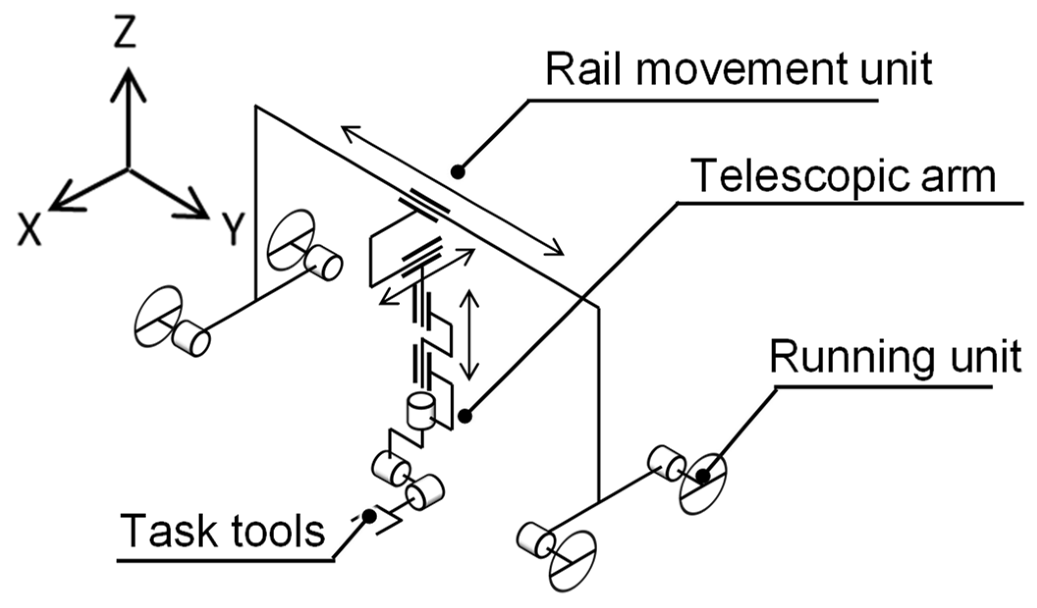
We configured the robot in such a way that it would be able to move in an agricultural field and perform tasks in a Synecoculture environment where multiple plants, including tall plants, are densely mixed. First, there are two methods of movement in fields, as shown in previous studies: moving on rails and running on the ground. Solar panels were installed in the upper section of the agricultural field, so the robots could be moved on installed rails by using their columns when operating on a large scale. However, laying large rails in experiments is cost intensive. Therefore, in this study, we set up a structure where a running unit was set up on a small rail so that it can run on its own and facilitate introduction into a temporary farm; the scale of the farms on which the robot works can be subsequently increased by increasing only the length of the rail, and the running unit does not need to be used. To execute its tasks, the robot needs to approach the target objects by avoiding dense plants; hence, the robot was given translational degrees of freedom in the X, Y, and Z directions and rotational degrees of freedom in terms of roll, pitch, and yaw. The degree of freedom in the X direction can be supplemented by directly running with the running unit, but tire-based running decreases positional accuracy due to slippage. Therefore, in this study, the rail movement in the X direction was used as is. The degrees of freedom that the robot developed in this study has is as shown in
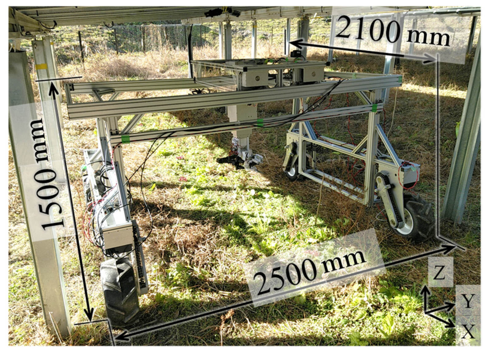
Figure 1; its structure includes a running unit that moves the robot itself on the soil, the rail movement unit that assists horizontal movement, and a vertical arm unit that assists in vertical movement of the work tool and positional changes. The vertical arm unit has a telescopic structure, which can execute multiple tasks as the work tools related to each task are installed on the tip of the vertical arm unit. Furthermore, each unit of the robot was designed for easy assembly/disassembly during transportation. Details of each unit are given later in the text, but the appearance of the developed robot is shown in
Figure 2.
2.4. Design of the Running Unit
The drive/steering configuration was set as a four-wheel drive/zero-wheel steering configuration that required relatively little space for turning, was capable of turning on the spot, and was low-cost. Tires and crawlers can be considered for running on rough terrain; however, they are not only expensive, but their maintenance cost is also high. As crawlers would be inferior to tires in this scenario, we decided to use tires for running. There are multiple patterns during tire-based running depending on the drive/steering configuration. The work lines in the agricultural field were separated by solar panels, so the robot will need to be able to switch between work lines to be able to work on all of them. Taking into account the roughness of the road surface, we considered installing a suspension; however, the use of low-pressure tires helped achieve the effect of suspension because of tire deformation. The distance between the tires that enables in situ turning was calculated. During turning, driving force and lateral force act between each tire and the ground. To prevent tires from slipping, the combined driving force
and lateral force
of each tire must be less than the maximum static friction force, as shown in Equation (1):
where
is the friction coefficient,
is the mass of the robot, and
is the gravitational acceleration. For turning, the counterclockwise moment of the center of rotation must be positive as in Equation (2). Therefore, the turning condition is expressed as in Equation (3):
where
is slip angle,
and
are the distance between the tires in front–back and right–left directions. The driving force
required for driving on a slope angle
is obtained by Equation (4):
The coefficient of friction was considered as 0.15, since the nominal value of the agricultural tires used is from 0.07 to 0.16. Based on the driving force and the required rotation speed
, the required motor power was calculated by Equation (5):
where
is the radius of a tire of 0.2 m and
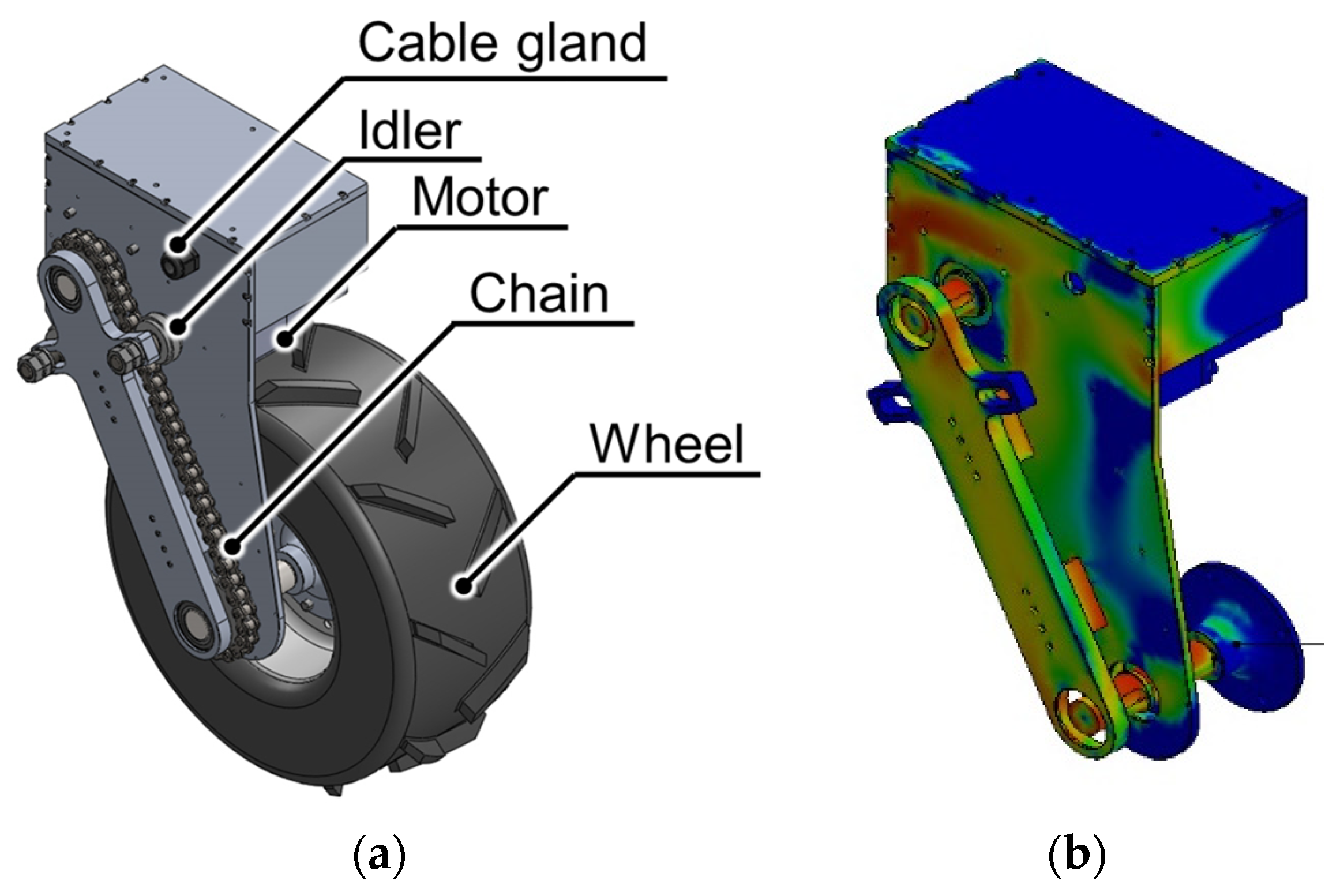
is the power transmission efficiency from a motor to a tire of 0.85. The required motor output was calculated to be approximately 325 W; thus, a 400 W motor was installed. A brushless DC motor BLV640N100F (Oriental Motor Co., Ltd., Tokyo, Japan) was used, and the power was transmitted by a chain that could handle high torque levels and had excellent environmental resistance (
Figure 3a). The distance between the tires in front–back and right–left directions
and
were determined at 1.8 m and 2.3 m. Overall, we used the finite element method to design the structure with sufficient strength (
Figure 3b).
2.5. Rail Movement Unit Design
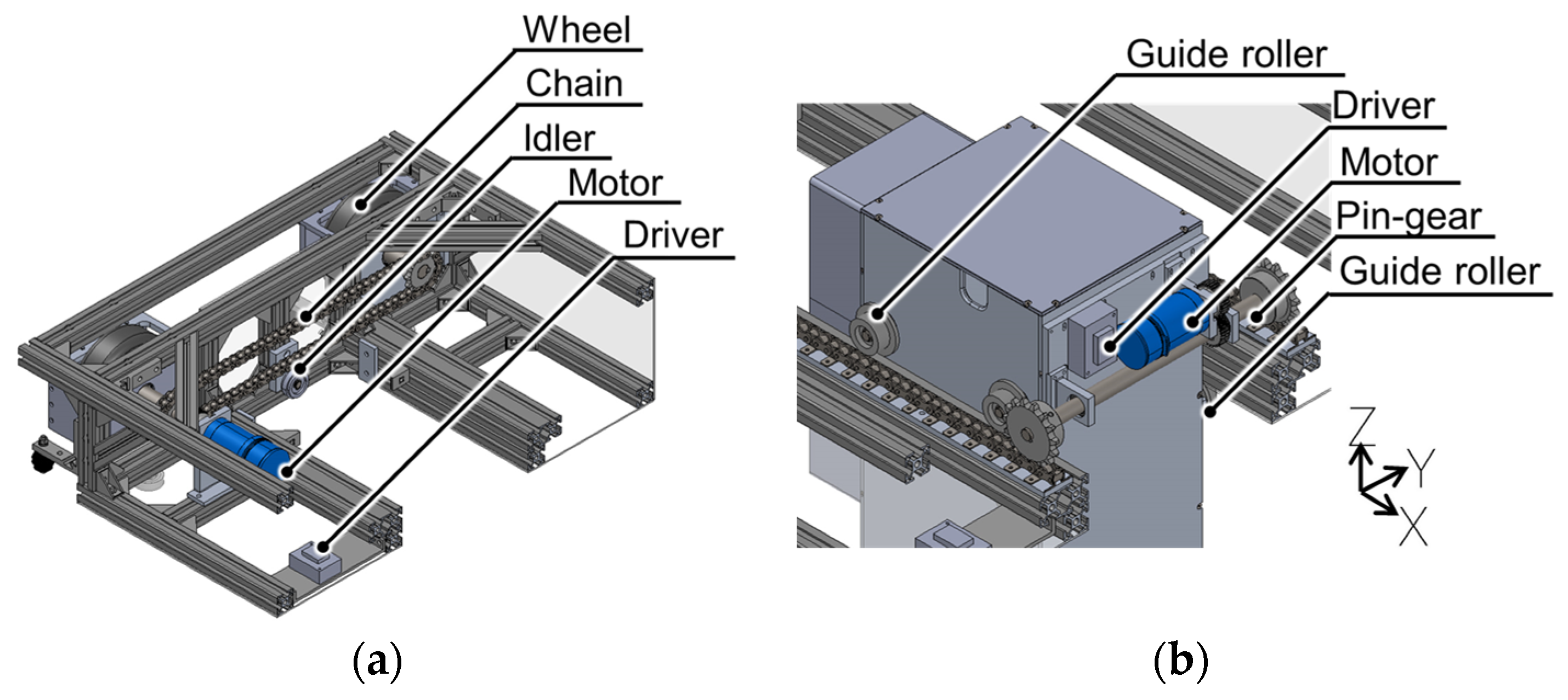
This robot was assembled and disassembled during transportation, so it is desirable to have a low assembly accuracy when integrating the robot. Additionally, as the robot must operate outdoors, environmental resistance is necessary. Therefore, it was decided that the linear motion in the X and Y directions of the rail movement unit would be conducted by the pin gear and wheels, respectively. The pin gear drive is a method of driving using a rack with a pin mechanism and a gear with a special tooth profile. The rail movement unit runs on rails; thus, the required output of the drive motor was calculated by the same mathematical formula as for the running unit described above. Additionally, a guide roller was attached to prevent the robot from coming off the rail or rack due to external forces or vibrations while performing tasks, thereby restricting the direction of movement (
Figure 4). The rails on which the rail movement unit moves and the robot frame that connects the running unit were composed of an aluminum frame. The size was determined not only by considering the width of the work line but also the conditions for not tipping over during sudden acceleration or sudden halt; the wheelbase that could turn and tread width was also considered. Furthermore, strength analysis was performed when there was an external force on the robot during a collision with plants and twisting when one of its wheels is locked.
2.6. Telescopic ARM
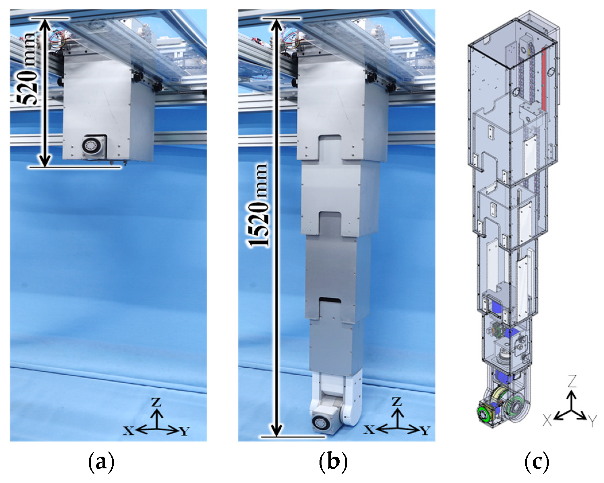
We designed a high stretch ratio arm that can perform various tasks and exert large force (
Figure 5). In this study, as the robot is designed for outdoor environments, it is assumed that raindrops would drip on the robot from the gap of solar panels. There is a need to devise ways that do not expose its mechanical or electronic parts. Rigidity is also required for accidental contact with obstacles such as shrubs. Therefore, we used a telescopic structure in which a nested rectangular parallelepiped housing was used for its ability to enclose the entire arm drive unit and obtain high rigidity. Four stages were used to achieve the contracted and fully extended lengths, and the posture of the end effector was determined by arranging the yaw, pitch, and roll axes at the tip. Crops could be harvested, and weeds could be pruned by changing the tools.
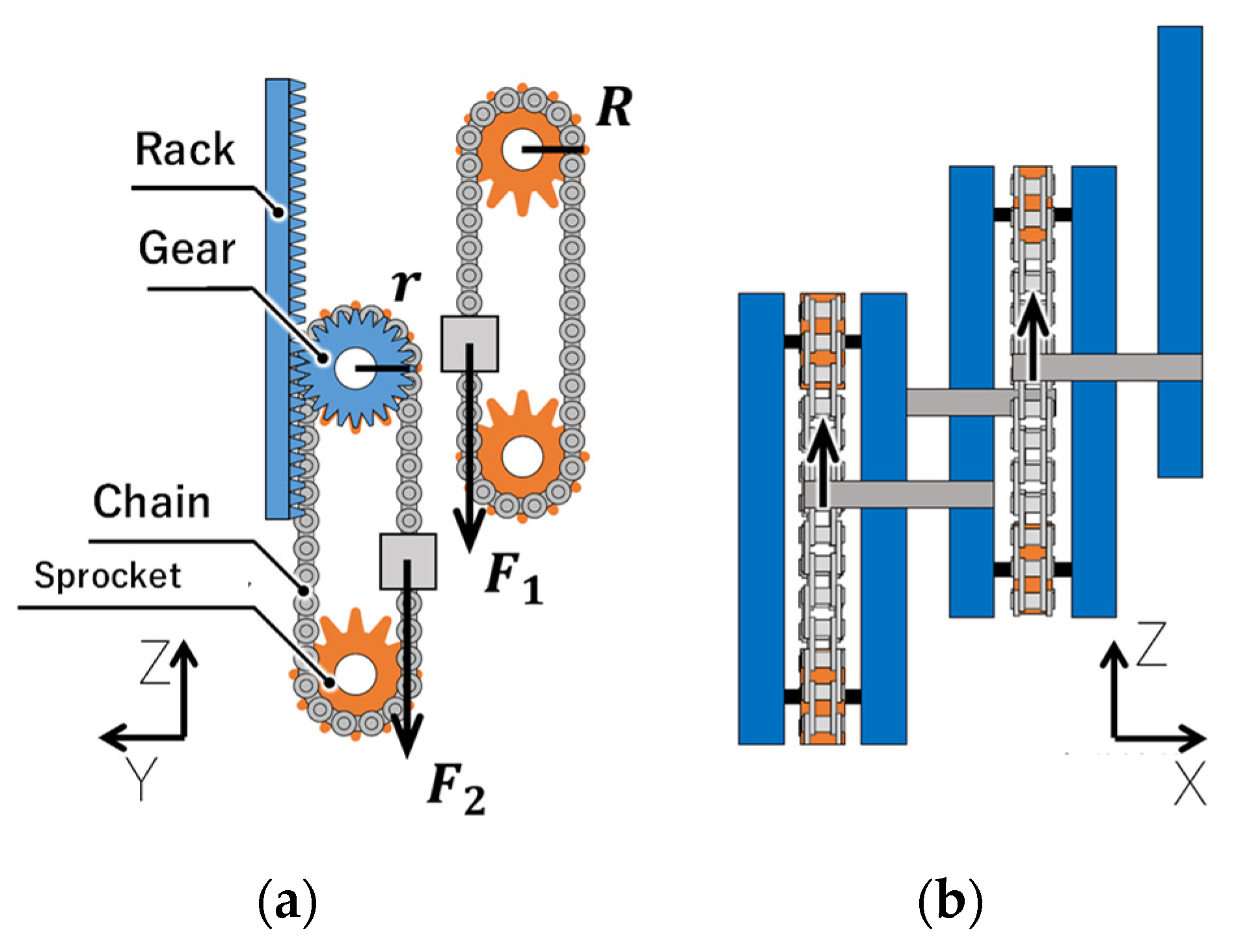
The drive unit of the telescopic arm had a motor in the first and fourth stages, with the motor in the first stage interlocking the second and third stages and extending the arm, and the motor in the fourth stage independently driving only the fourth stage. The second and third stages were connected to the higher stage with a chain. The motor rotation was transmitted to the sprocket, and the second stage expanded and contracted as the chain moved. The rack was placed between the first and second stages, and the gear was placed in the second stage, so that it latched with the rack and rotated with the extension of the second stage. The mechanism used was such that the gear rotation rotated the coaxial sprocket, which then interlocked with the third stage and extended it (henceforth, referred to as the interlocking unit) (
Figure 6). Regarding the chain interlocking mechanism, the force
and the torque
applied to the second sprocket can be expressed by the following equations:
where the mass of parts below the third-stage housing is
, the frictional forces applied between the second-stage and third-stage housing is
, and
is the pitch circle radius of the sprocket. The force
and torque
applied to the first-stage sprocket can be expressed by Equations (8) and (9):
where the mass of the second-stage housing is
, the frictional forces applied between the first-stage and second-stage housing is
, and
is the pitch circle radius of the gear. This mechanism enabled expansion and contraction without having an actuator in the central stage, allowing for the robot to be stored compactly. Moreover, the mechanism would not be exposed to the environment. The use of a worm gear with an advanced angle of less than 4° for the reducer of the motor that drives the arm enables the posture to be maintained due to friction between the worm wheel and worm gear even when power is cut. The power required for the motor was calculated as 166 W with the required torque
, the required speed and the power transmission efficiency of the gears and belts between the motor and the sprocket of 0.45 with almost the same calculation as Equation (5).
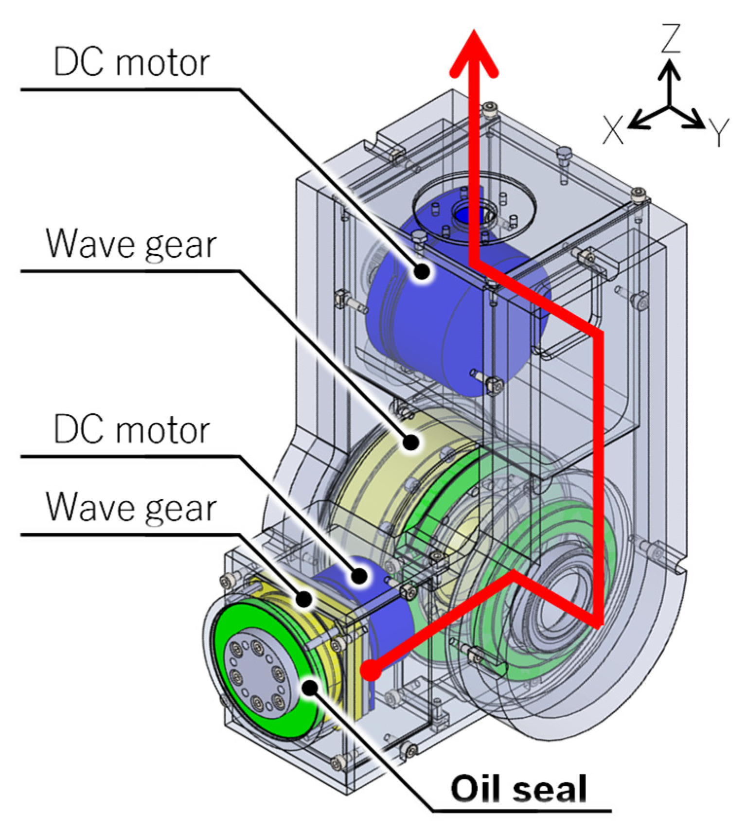
With this mechanism, the total stroke of the second and third stages was 600 mm, and the stroke of the fourth stage was 420 mm. A nylon plate was sandwiched between the housing of each stage to reduce friction during sliding. The pitch and roll axes used wave gears for the reducer, because of which they could obtain a high reduction ratio; hence, even large crops could be harvested and transported (
Figure 7). The yaw axis used a hollow structure to allow the wiring of the pitch and roll axes to pass through the fourth stage; a motor driver (Maxon Co., Ltd., Sachseln, Switzerland) for driving the yaw, pitch, and roll axes of the fourth stage was placed in the fourth stage. The wiring that connected the PC, power supply, and motor driver passed through the housing and extended from the top of the robot to the outside.
2.7. Pruning/Harvesting Tool
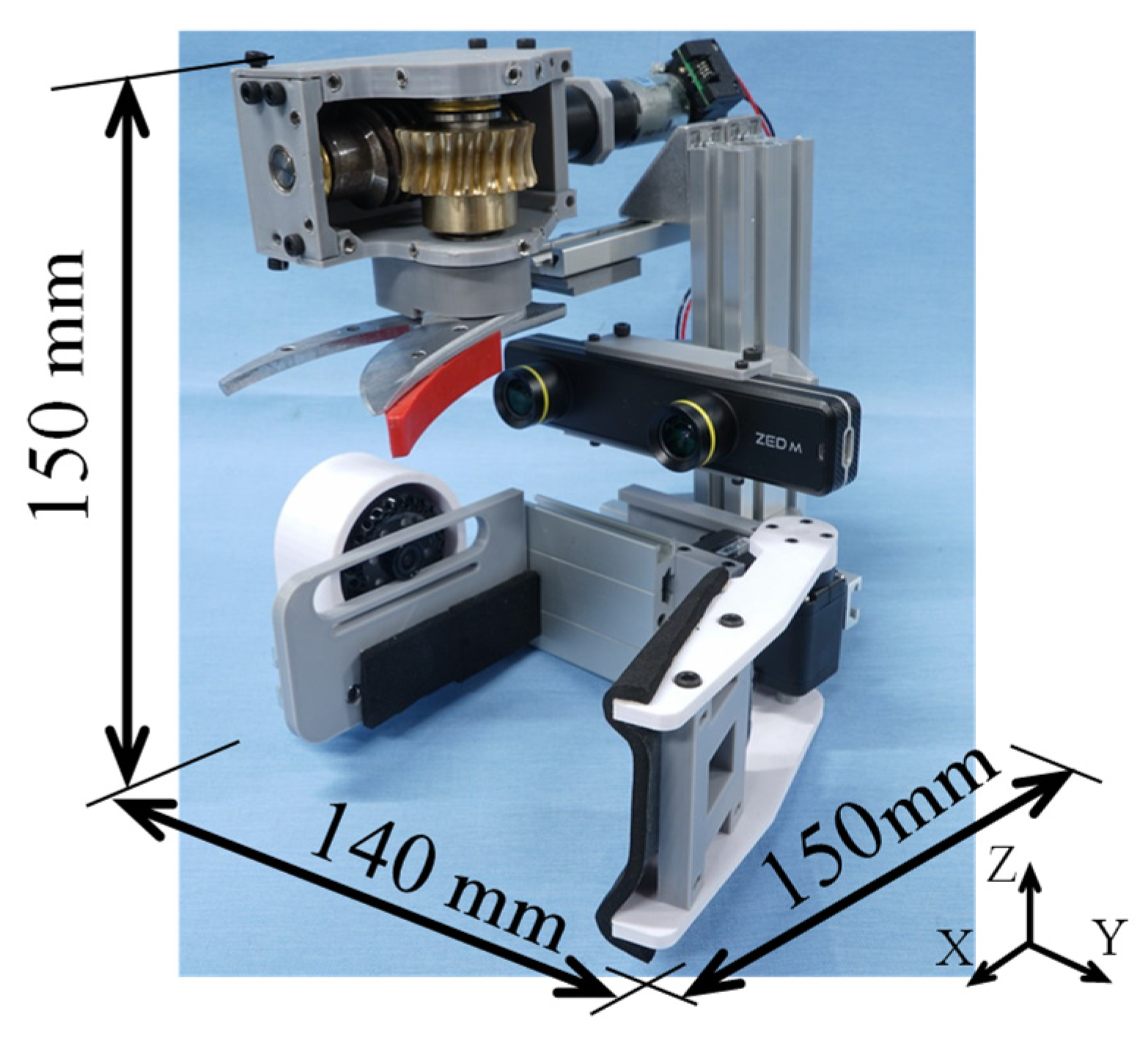
Figure 8 shows the design and manufacture of a pruning/harvest tool. Assuming that the harvest of vegetables that mature hang down from branches, the structure was designed in such a way that the grip unit was at the bottom, the sensor unit was at the center, and another grip unit was at the top. A pruning scissor blade, DC motor, and worm gear were used for the cutting unit because the required cutting force and stroke were large. In the pruning pre-test with scissors in the field, it took the cutting force
of max. 53 N for spinach and max. 120 N for an eggplant. A mechanical model of a pruning scissor is shown in
Figure 9. The required torque of the cutting scissor
was calculated with the cutting force
of 120 N and a blade length
of 0.07 m in Equation (10):
Since it was assumed that the cross-sectional shape of the objects will mostly be circular, the grip unit structure was such that the position could be determined by two points on the fixed side, which then enabled three-point support, with a claw on the movable side that can be fixed as the third point. The movable side of the grip was driven by a servomotor AX-18A (ROBOTIS Co., Ltd., Gangseo-gu, Seoul, Republic of Korea). Additionally, the cutting unit was equipped with a slide rail that could be adjusted back and forth, and the grip unit was equipped with a slide rail that could be adjusted left and right. This was for adjusting the positional relationship between the cutting unit and grip unit to enable a three-point grip with a narrower width for other types of fruit/leafy vegetables or a two-side grip increasing the contact area. Additionally, the sensor unit does not require front–back adjustment, so a similar slide rail that could adjust the left and right positions was adopted, and a ZED mini [
38] (Stereolabs Inc., San Francisco, CA, USA) was installed so that the operator could visually recognize the harvested material and sense the distance to the harvested material.
2.8. Seed Ball Sowing Mechanism
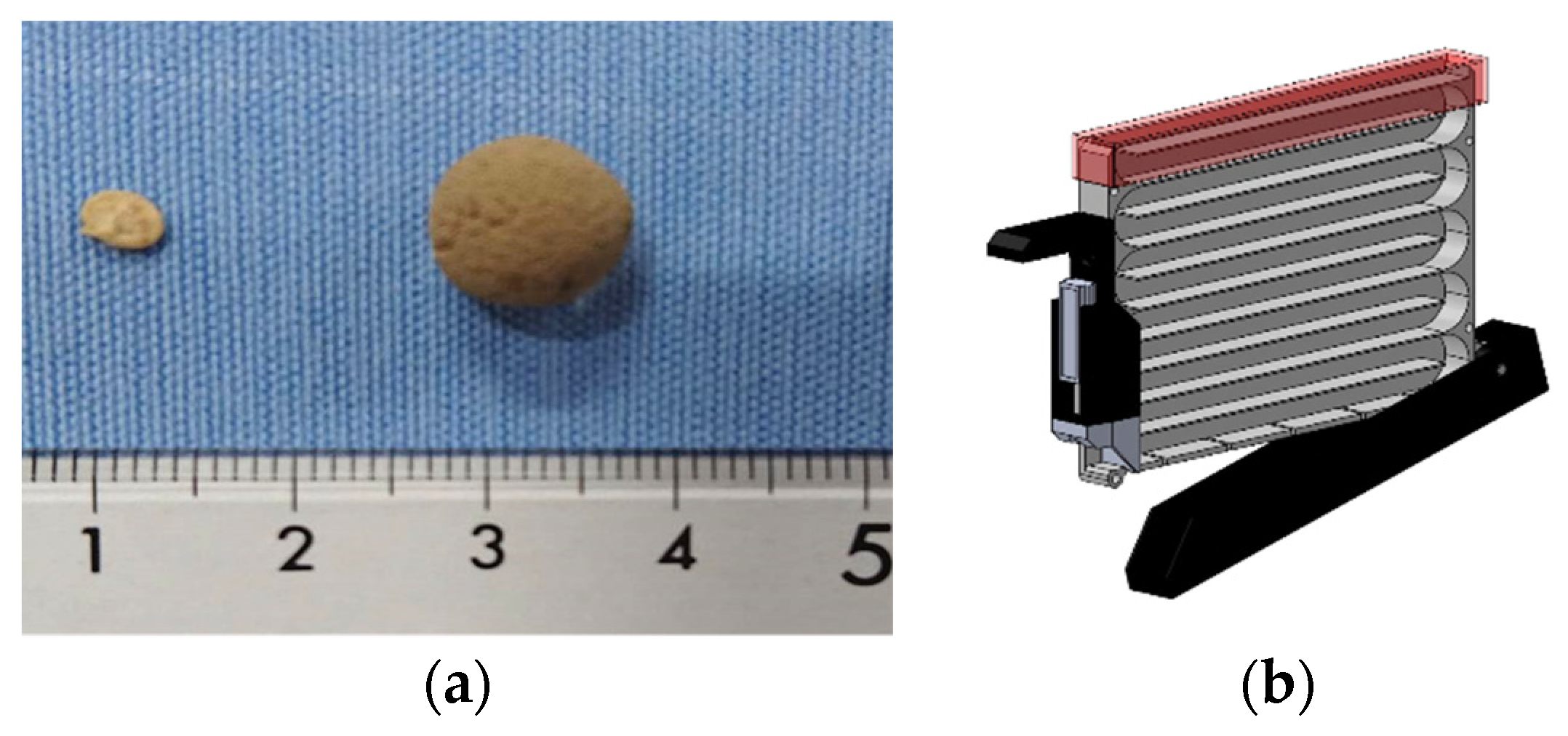
As various crops are cultivated in Synecoculture, the shape and size of seeds also vary. Therefore, the shape and size were made uniform by covering the seeds with soil, thereby allowing for sowing with the same machine regardless of the type of seed (henceforth referred to as a “seed ball”). The shape was made spherical so that it could easily pass through the pipe of the sowing mechanism described in the following sections. The balls were molded by compressing and hardening the soil that contained the seed. The particle size was set to 10 mm to accommodate the seeds of multiple crops (
Figure 10a). The seed balls were stored in a tank for each seed of the same species, and the tank was mounted on top of the sowing mechanism of the robot. The tank mechanism was rotated back and forth to move the seed balls inside, and a spring-loaded partition plate was used to discharge each seed ball (
Figure 10b).
We decided to use anchors instead of drills to make holes in the ground, as that will not disturb the roots and leaves of several plants already existent in the Synecoculture environment.
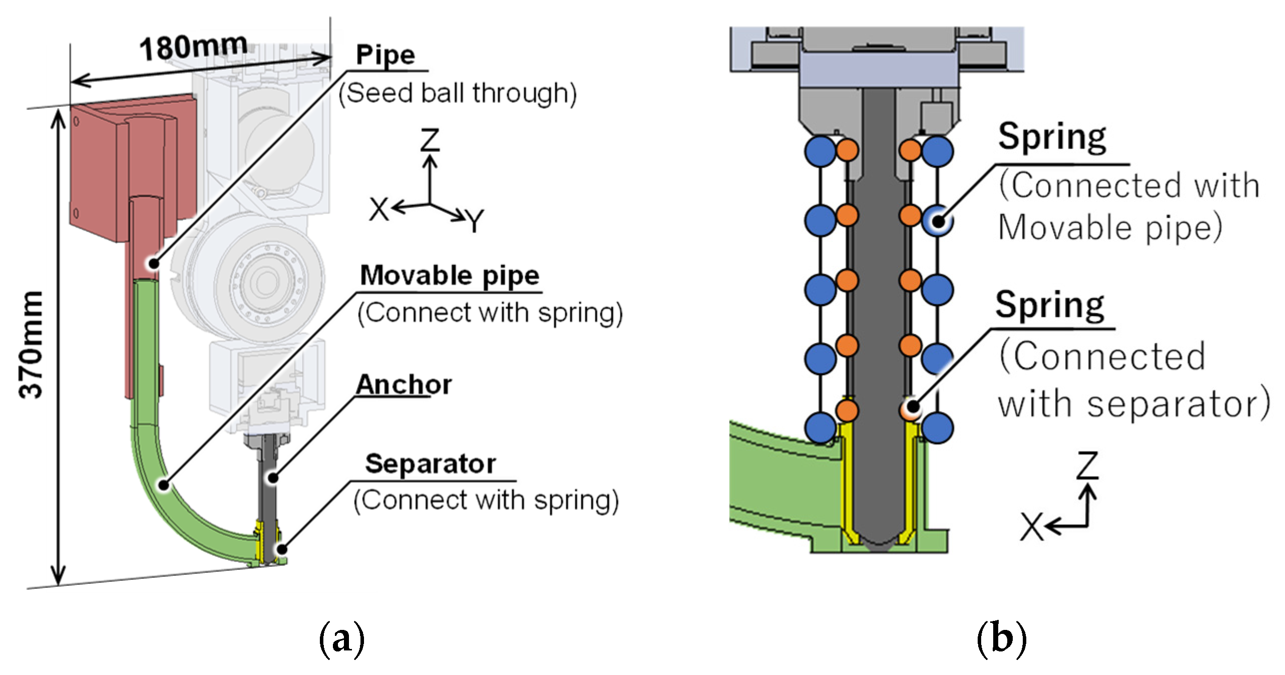
Figure 11 shows the sowing mechanism that was manufactured. A
anchor was attached to the arm tip according to the particle size of the seed ball. When a hole was dug with the anchor using the arm extension, the discharge outlet was blocked by the separator, so the seed ball that moved in the pipe during this time stayed in front of the discharge outlet. Simultaneously, the separator also prevented the intrusion of excavated soil into the pipe. The pipe through which the seed ball passes then slides in the Z-axis direction and connects to the arm with a compression coil spring (
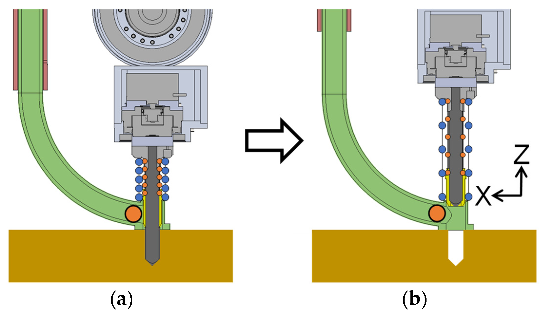
Figure 11a,b). When the arm was extended, the compression coil spring was compressed between the robot and the ground surface; as a result, only the anchor was inserted into the ground, making a hole (
Figure 12a). After the seed ball is put into the pipe, the arm contracts and the anchor are pulled out. At this time, the pipe stays pressed against the ground as a result of the compression coil spring and gravity. Like the pipe, the separator is also connected by a compression coil spring, but because the natural length is different, the discharge outlet is released by contraction, discharging the seed ball (
Figure 12b). Therefore, this enabled the seed ball to be accurately dropped in the position of the hole opened by the anchor. The seed ball can then be buried in the ground by pressing the anchor to the ground surface by extending the arm a second time so that the seed ball does not remain on the ground surface or partially in the hole.
2.9. Robot System Configuration
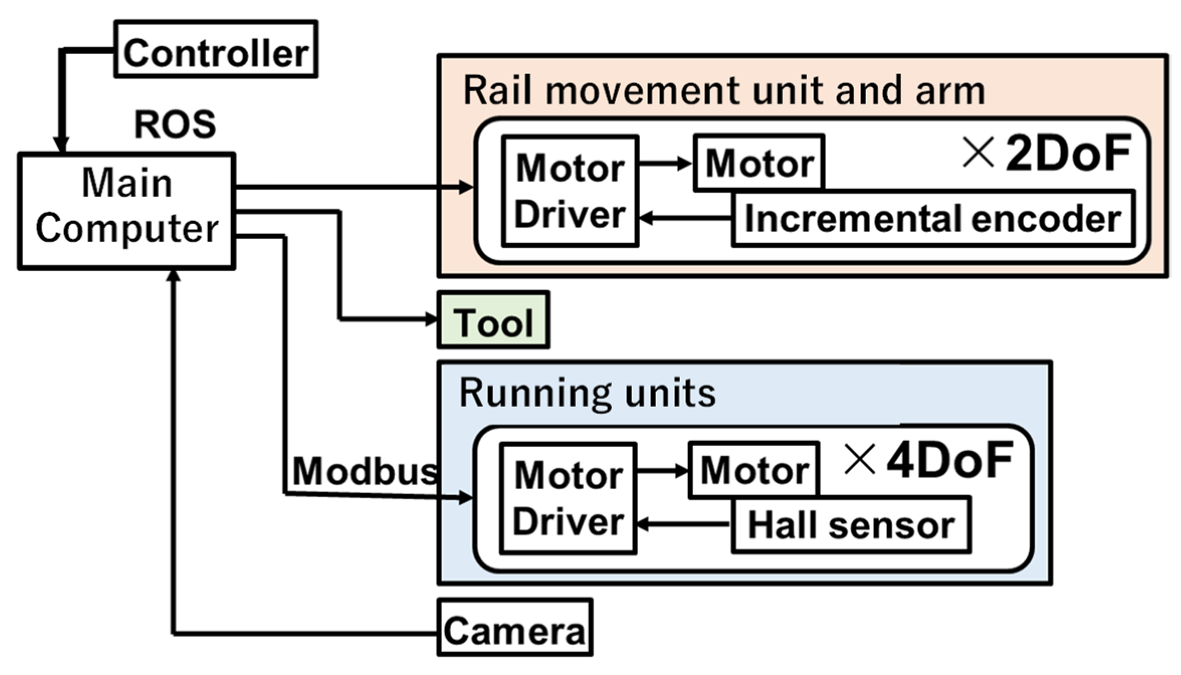
The system configuration of the robot is shown in
Figure 13. Each component in the robot was integrated using ROS (Robot Operating System). Modbus communication was used between the main computer and running units and USB communication for the rail moving unit, tools, and cameras. As a motor driver, BLVD40NM (Oriental Motor Co., Ltd., Tokyo, Japan) is used in the running unit and EPOS4 Compact 50/5 and EPOS4 Compact 50/8 (Maxon Co., Ltd., Sachseln, Switzerland) in the rail moving unit and a telescopic arm. The output voltage to the motor is controlled by a velocity proportional derivative control in each motor driver. An operator operates tasks using a game controller based on multiple camera images installed on the robot.
2.10. Operation UI for Densely Vegetated Areas
As a simple operation system, it is possible to monitor the scene by presenting an overhead view and using a commercially available controller. However, in dense plant environments, the bird’s-eye viewpoint is easily blocked by dense vegetation, and it is sometimes difficult to recognize harvested products and obstacles in the shade. Therefore, we considered that the use of a 360° camera and parallel presentation of the tool’s viewpoint image and bird’s-eye viewpoint image would enable recognition of a wide area of the environment surrounding the tool. And we aim to achieve recognition of dark areas by adjusting the brightness of the camera image. For ease of adaptation to the operation system, we considered simplification of operation by developing a tool coordinate-based operation. In addition, we considered that simple tasks could be automated to shorten the work time and reduce the burden on the operator, rather than having the operator give detailed control instructions.
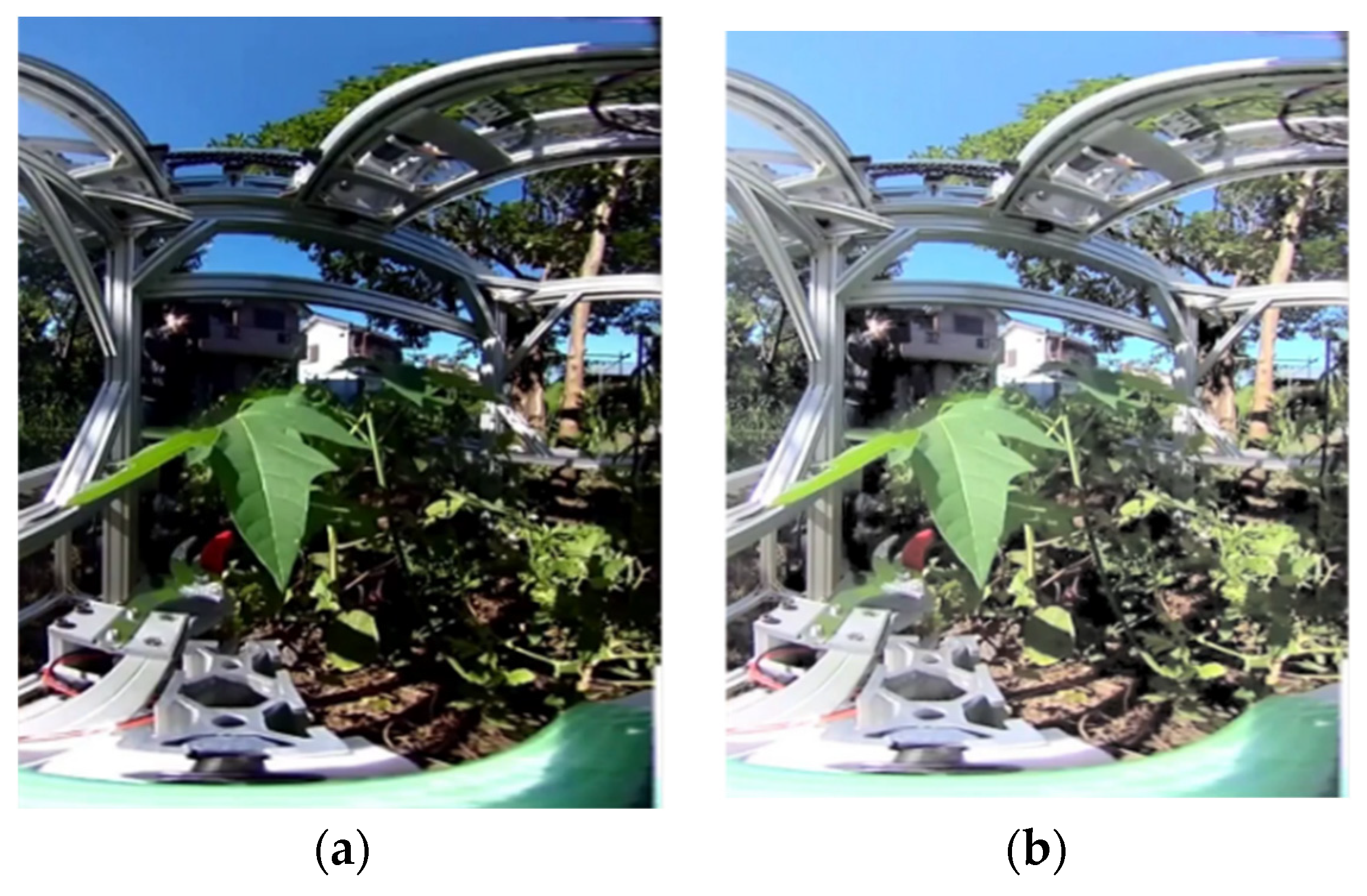
The 360° camera used for the tool viewpoint was the Ricoh Theta V, which can be linked to the ROS used in the current system and has a shooting distance of at least 100 mm. The system was constructed to present FHD/30 fps images via USB connection to a PC, and the delay was approximately 230 ms. In an environment with dense vegetation, the shadows of branches and leaves of other plants were very dark, and visibility was greatly reduced. Therefore, we decided to correct the luminance histogram of the camera image using gamma correction, which can enhance the luminance of dark areas (
Figure 14).
In order to realize the control command input while viewing the tool’s camera, the joystick input by the operator assuming the tool camera coordinate system was transformed to the robot coordinate system by the transformation in Equation (11) to match the tool camera coordinate system and the operator’s control coordinate system.
is the velocity input vector in the tool camera coordinate system, and
is the velocity input vector in the robot coordinate system, and
is the quaternion that represents the rotation from the tool coordinate vector to the robot coordinate vector. Correspondence between controller operation and robot movement is presented at both ends of the lower side of the monitor, which is considered not to interfere with the user’s field of view during operation.
In addition, a radial menu, which can be easily selected with a joystick, is used to display the menu for switching tasks during operation. By providing the coordinates of the sowing target point, the system automatically moves the sowing tool to the target point, rotates the sowing tool, inserts the sowing tool into the ground, and discharges the seed dumplings.
3. Results
3.1. Rough Terrain Running Ability Test
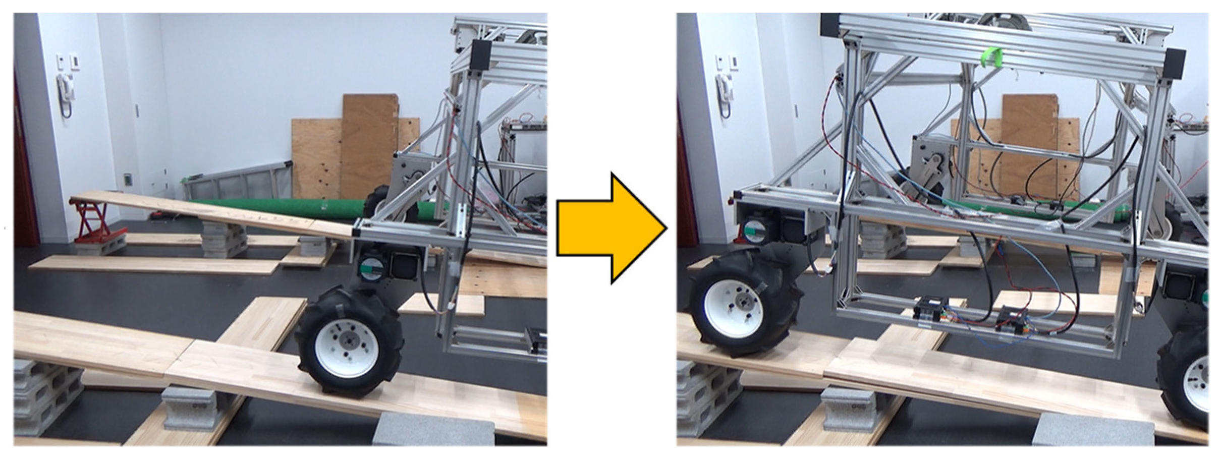
In a laboratory, we first verified whether the robot was able to climb a slope with an inclination angle of 5° and overcome a step of 50 mm in height, as per the required specifications. A concrete block, jack, and wooden board were placed to prepare a sloping environment. The steps were prepared by placing the wooden board on the floor for the rough environment. The robot succeeded in traversing a 7.5° slope (
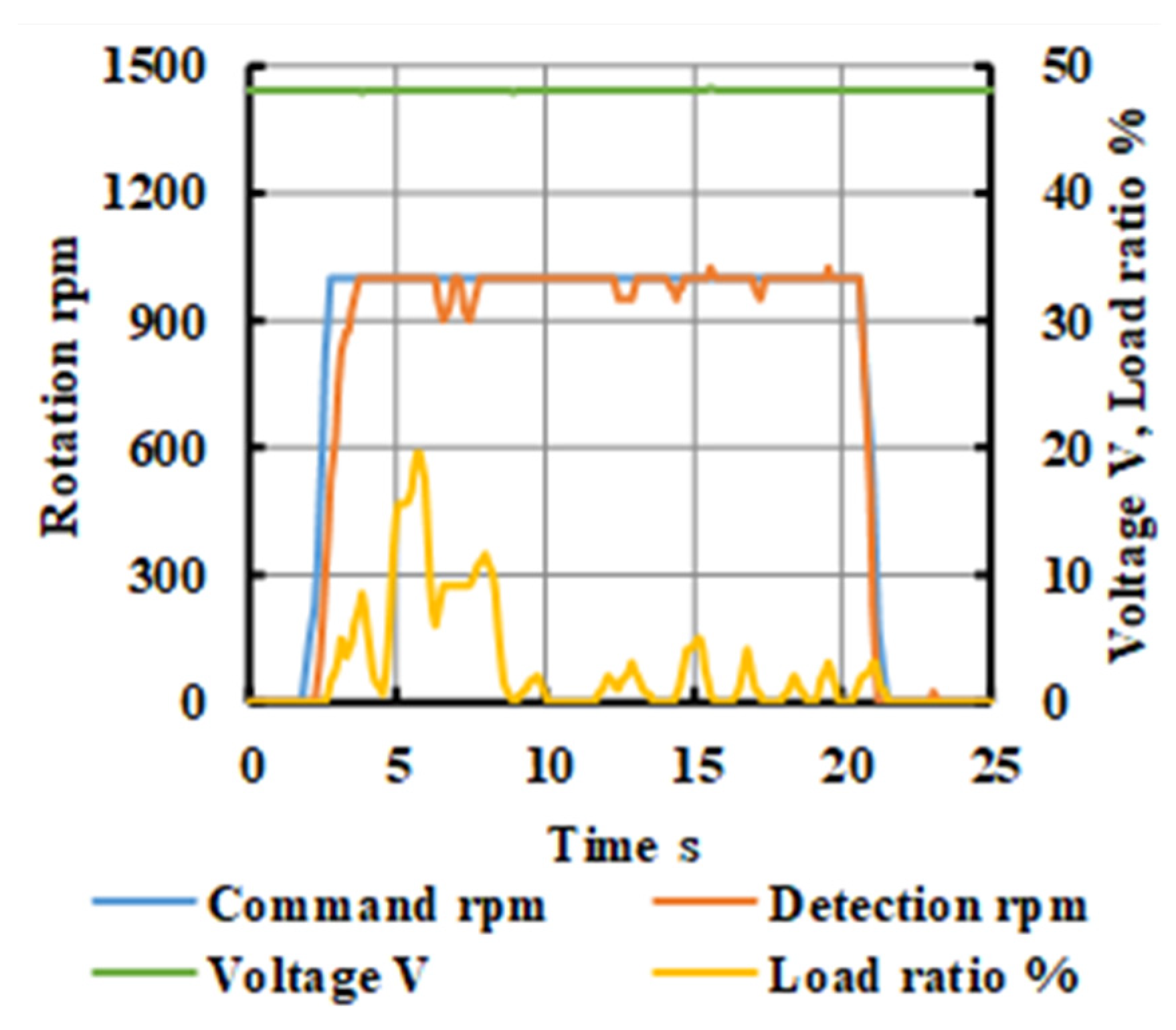
Figure 15) and 5.6 cm step. The tire rotation command value and measured value when overcoming a step that requires instantaneous power and the load factor concerning the allowable current are shown in
Figure 16. The maximum load factor at the moment of overcoming the step was 34% of the power of an actuator of the running unit; hence, it was concluded that sufficient torque was secured. Furthermore, we ran the robot at a speed of 45 m per minute in an actual agricultural field to confirm its ability to run on a farm where Synecoculture is being conducted. Given that there was a slope of around 0–5° in the direction of the movement of the robot in the agricultural field, it can be said that there was a sufficient torque margin even when the robot was running in an actual field. The agricultural field in which experiments were conducted had rough terrain, as expected, in addition to the previously mentioned slopes, and some weeds were densely growing on the running surface. It was confirmed in this experiment that the robot was able to run in a straight line even when the ground was not maintained for the operation of the robot.
3.2. Arm Extension Force Measurement Experiment
To confirm whether the telescopic arm manufactured in this experiment meets the required specification of the extension force and could operate normally in hard soils, we measured the load when holes were made in the compact soil. A bucket filled with the same soil as that in the field was placed on a load cell platform scale, and holes were made by the sowing mechanism by arm extension. The load at the time of hole opening was measured from the difference between the measured values of the platform scale. A total of 12 trials were conducted, and the maximum and average values are shown in
Table 2. It was confirmed from the experiment that holes could be made in soils harder than those expected in the field.
3.3. Arm Extension-Based Sowing Operation Experiment
It was tested in this experiment that the seed balls could be buried in the soil using the arm and sowing mechanism. Holes were made in the ground using the anchor with the extension of the interlocking unit of the arm. The insertion depth was 30 mm. The arm was contracted and then extended a second time to bury the seed ball. A series of operations were conducted until the seed balls were buried, with a total of 12 trials conducted.
We succeeded in burying seven out of 12 seed balls. Arm extension-based hole opening was successfully conducted in all trials. Additionally, it was confirmed that when the seed ball was discharged, all of them were either inside the hole or in the upper section of the hole. Cases where the robot failed in its sowing action were those where the seed ball was stuck inside the pipe or near the discharge outlet even if the discharge outlet was released. This was thought to be due to the small inclination of the pipe near the discharge outlet.
3.4. Evaluation of the Pruning Time of Leafy Vegetables on the Agricultural Fields
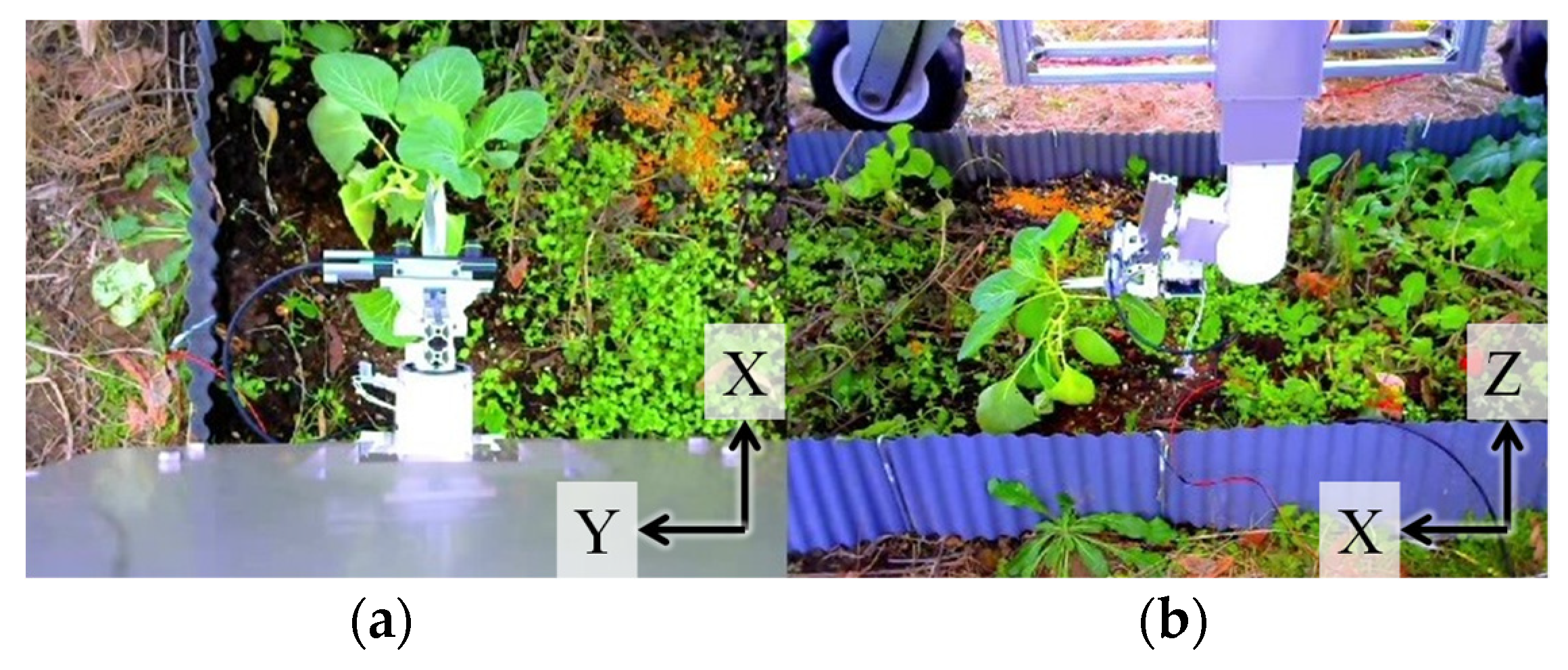
We conducted pruning of leaves in the farm to confirm whether pruning was possible with the current system and to verify the required time. The operator only used information from the cameras installed on the robot to prune a lettuce stalk at a point approximately 300 mm away from the arm. During this process, the tool was moved by operating the controller without seeing the actual object. This pruning trial was conducted six times. Out of the six trials, three were conducted where the XY table movement speed was twice that of its upper limit. The time required for the experiments is summarized in
Table 3. Korean lettuce was pruned several times. The video information presented to the operator during the task is shown in
Figure 17. It can be seen from the presented video that the camera was far away from an object, and the object was small in the video; the video information presentation was not sufficient, and the visible range was narrow. One of the problems was the interference between the robot and plant, due to which visual recognition could not be achieved, which in turn increased the work time, as shown in
Table 3.
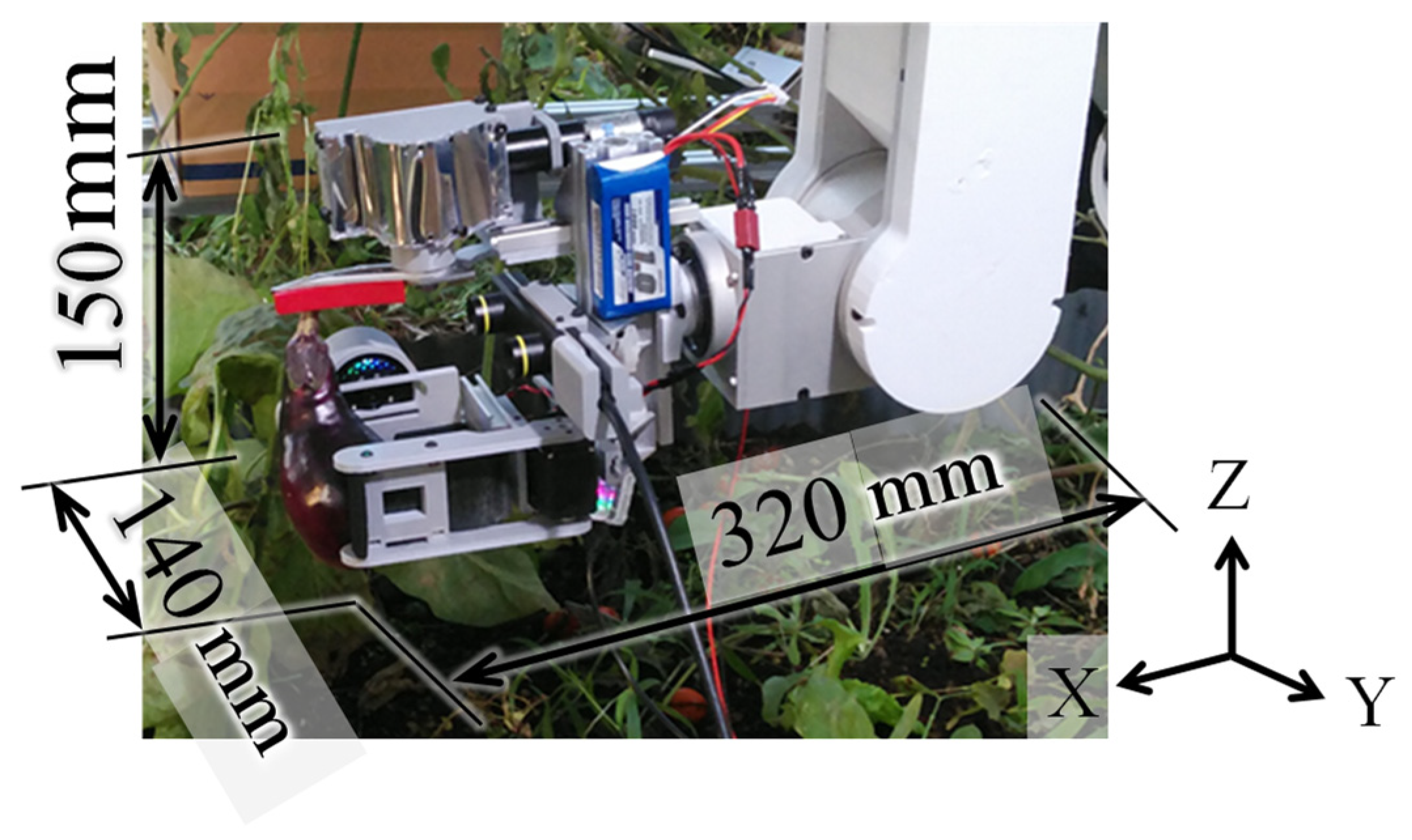
3.5. Eggplant Harvesting Experiment on Farmland
The rail moving unit and vertical arm unit were used in a Synecoculture farm to approach the eggplant for harvesting using the harvest tool. As shown in
Figure 18, the robot successfully harvested the eggplant several times during the experiment. It was confirmed in this experiment that crops could be harvested in a Synecoculture environment, but the eggplant branches interfered with the harvest tool during the execution of the task, and, because the entire eggplant crop was pressed, the distance could not be shortened, which extended the work time. In the future, we must change the harvest tool settings or develop a sub-arm that grips the subject crop itself and fixes it.
3.6. Operation System Evaluation in a 3-Task Sequential Operation Experiments
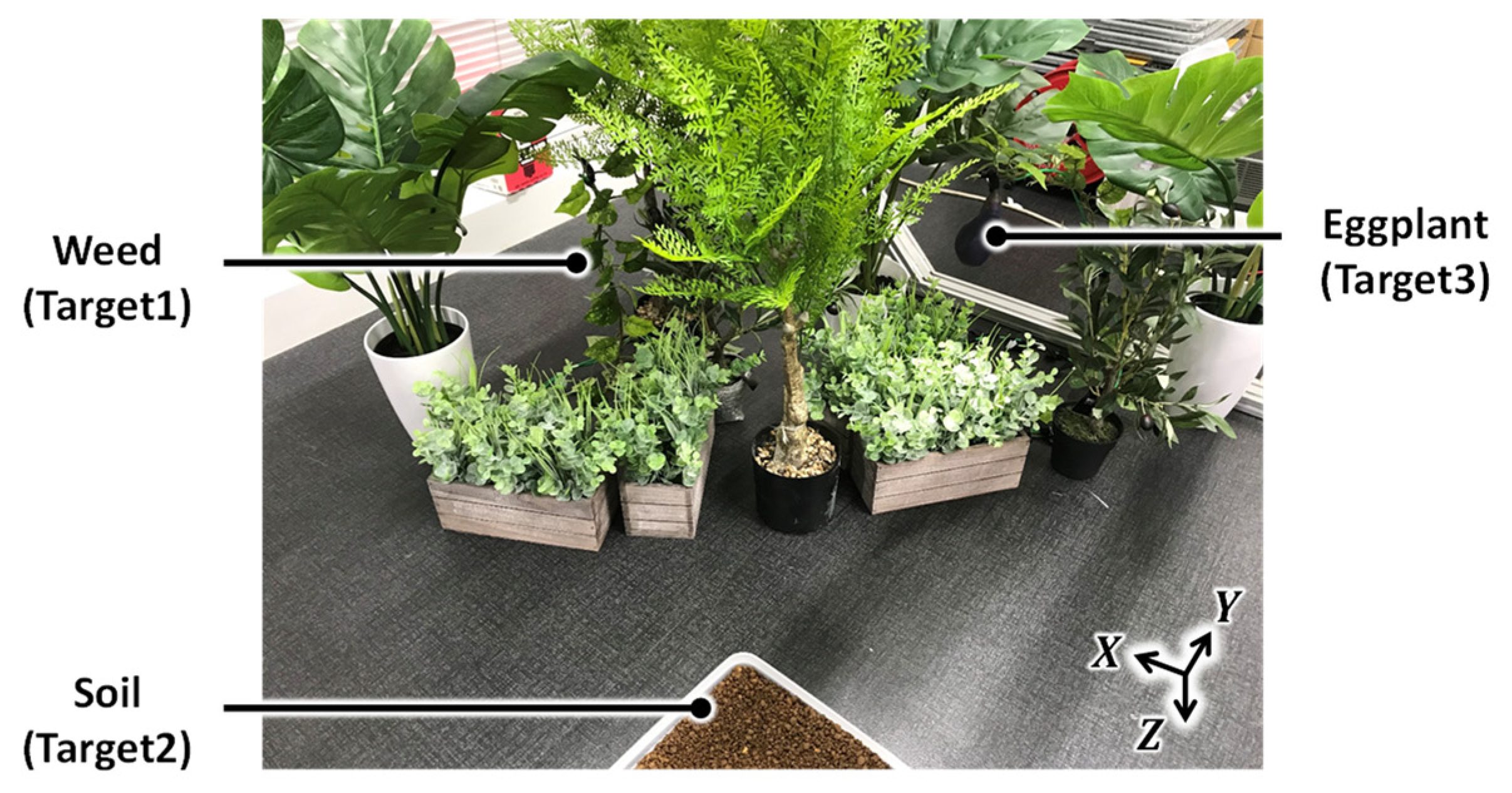
In order to confirm the improvement in operability of sequential operation of weed pruning, sowing, and harvesting in a densely vegetated area, we conducted an evaluation experiment using two control systems: the general control system A, which presents a bird’s-eye view and gives operation commands based on the robot coordinate system, and our proposed system B. In particular, we verified the control system in a complex environment in which another plant exists in front of the target plant and interferes with the robot’s work. The subjects were six healthy adults, three of whom performed the experiment on system B after the experiment on system A. The remaining three subjects performed the experiment with system A after the experiment with system B. First, after explaining the operation method to the subject, the subject performs a test run for a few minutes. Then, the subjects were asked to repeat the three-task sequence using operation system A three times in the same environment. Then, the subject repeated the operation using operation system B three times in the same environment. Reproducing the relative positions of plants in Synecoculture farm, an experimental environment was prepared in which the distance between plants was approximately 10 cm, which was too close compared to the conventional agriculture plants (
Figure 19). Examples of the video images presented to the subjects during the experiment are shown in
Figure 20. In order to maintain the same experimental environment for multiple experiments conducted by multiple subjects, the grasping and cutting motions were not performed, and the subjects worked until the tool came into contact with weeds or harvested targets. Before the start of the experiment, the subjects were informed that the evaluation items were operation time and the rate of interference with obstacles and that they were required to operate the robot as fast as possible while avoiding obstacles as much as possible. The total time required for three sequential tasks, the interference rate with obstacles, and the results of subjective evaluation by a questionnaire after the operation were compared as the evaluation items in the experiment. For the interference rate with obstacles, we checked the interference time with plants (obstacles) other than the target object by checking the experimental video taken from outside the experimental system. The interference time was used to calculate the interference rate as the ratio of the interference time to the total operation time. For the subjective evaluation, we used the NASA-TLX [
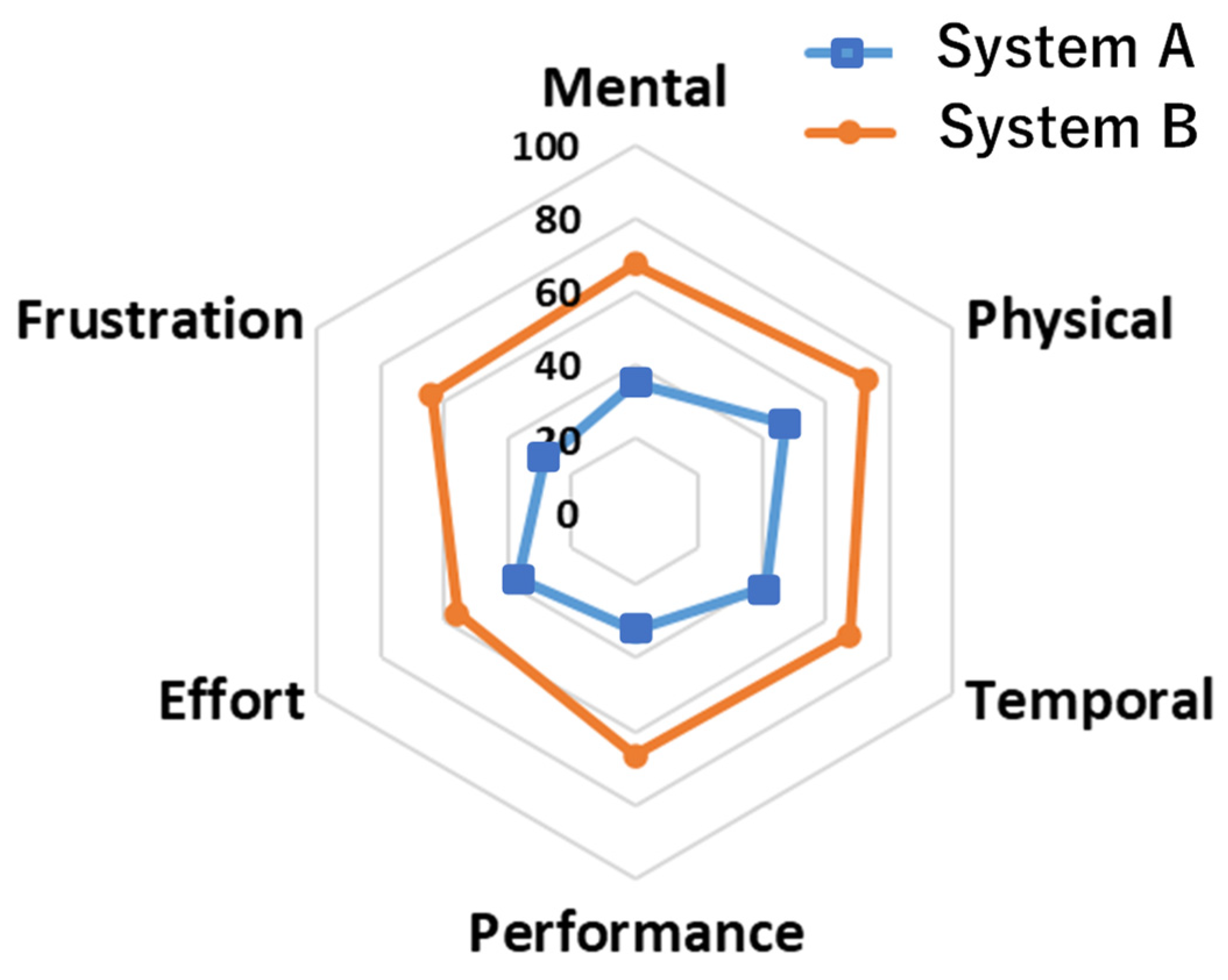
39] questionnaire method, which quantitatively evaluates the load index in a task subjectively. Parameters of 0 (BAD)—100 (GOOD) was used as the score. This experiment was approved by the ethical review committee of our institution (2019-163).
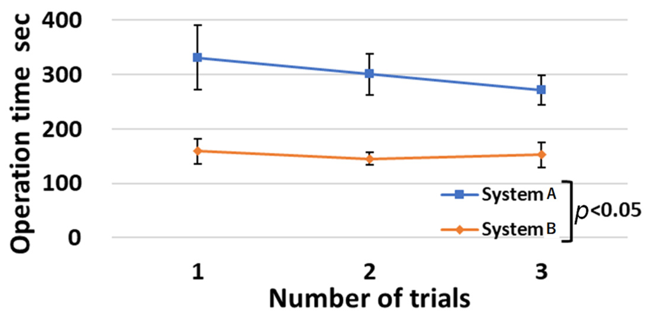
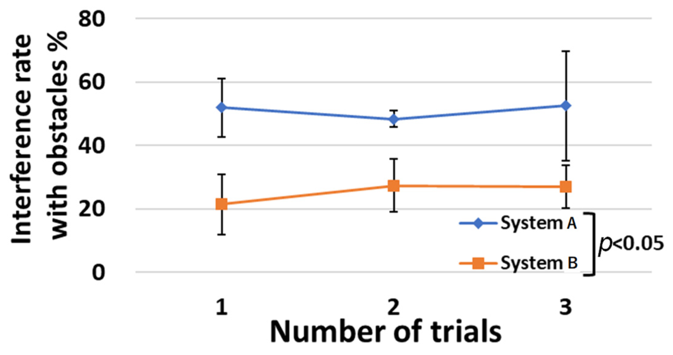
Table 4 and
Table 5,
Figure 21 and
Figure 22, show the operation time and interference rate with obstacles for each trial. In the task sequence, the operation time was reduced by 49%, and the interference rate with obstacles was reduced by 26%. The results of the NASA-TLX questionnaire survey are shown in
Figure 23. In all items, system B was rated higher than system A.
4. Discussion
Significant differences (
p < 0.05) between system A and system B were confirmed for the first, second, and third trials of the three-task sequential operation experiment. Thus, the use of the developed system B reduced the operation time and the rate of interference with obstacles. In
Figure 21, the operation time of system A decreased as the number of trials increased. On the other hand, the operation time of system B remained stable at around 150 s from the first to the third trial. The smaller standard deviation of the operation time for system B than for system A indicates that there are fewer individual differences in operation time. When comparing the group of subjects who experimented with systems A and B in that order with the group of subjects who experimented with systems B and A in that order, both groups had lower operation times and interference rates when using system B. From the above points, system B is considered to be easier to learn and easier to adapt for beginners than system A.
Although the interference rate with obstacles is reduced by system B, the value is not 0%. Ideally, the interference rate with obstacles should be 0%, but in reality, the distance between plants is often smaller than the size of the robot’s arm and tools in an environment where plants are as dense as in an actual farm environment. In this experiment, the obstacles were placed at a distance of approximately 10 cm from the target object, making it difficult to achieve a 0% interference rate in this experiment. In such an environment, if the robot can intentionally contact and slightly shift the obstacle, as a human farmer carefully does, it is thought that unexpected contact will be reduced, and both the target and the obstacle will be less likely to be damaged. In the future, we will also consider the use of an assistive arm for obstacle removal work.
The developed robot has been in operation for about six months in the field, and we were able to confirm new operational issues. Since the robot is operated outdoors, dustproof and waterproof structures of the robot were considered from the design stage. However, in practice, not only dust and rainwater but also insects’ contact and invasion with a robot were observed. The waterproof structure was designed assuming there are gaps in the solar panel and rainwater from the side, but insects can invade from all directions. Therefore, it is necessary to adopt a cover structure. Next, because the experiment was performed in winter, it was frosty on the farm. Therefore, it was confirmed that water droplets were generated inside the robot. There is a high possibility that it will break down due to water droplets, so it is necessary to provide protection for electrical materials and structures. In addition, heat dissipation must be taken into consideration in actual long-term operation in summer.
5. Conclusions
In this study, we developed an agricultural robot that could work in an environment where different types of plants were densely mixed, which conventional robots could not handle. We greatly improved the versatility of the robot by using various tools and standardizing seeds in the form of a “seed ball”. We showed that this robot was able to move in an actual agricultural field under solar panels and achieve the three main tasks of sowing, pruning, and harvesting. Using the developed operation system, we achieved a 49% reduction in operation time and a 26% reduction in the rate of interference with obstacles in a three-task continuous operation, compared to a simple controller.
The perspective of this study profoundly differed from those of conventional farming methods in terms of the high level of biodiversity and combination of solar panels. Further studies should be conducted to achieve an autonomous agricultural robot for practical and large-scale application in Synecoculture. Existing challenges include, automatic environmental recognition, assurance of sufficient battery power, robustness for long activity periods, improvement of operability, automation combined with image analysis, and reduction in the overall cycle time and costs. We plan to further advance our research and development, as well as to verify the effectiveness of Synecoculture operation methods on biodiversity and regreening effects in the field, and to develop this into a social implementation that contributes food production to the recovery of global ecosystems and the prevention of climate change.
Author Contributions
T.O., A.I., H.M., M.M., S.Y., K.T., T.T., K.M. and A.T. developed the agricultural robot; T.O., A.I., H.M. and M.M. performed the experiment; S.A., M.F. and A.T. helped to draft the manuscript. T.O. wrote the paper. All authors have read and agreed to the published version of the manuscript.
Funding
This research received no external funding.
Institutional Review Board Statement
The study was conducted in accordance with the Declaration of Helsinki and approved by the Ethics Committee of Waseda University (2019-163).
Data Availability Statement
Not applicable.
Acknowledgments
This study was conducted with the support of the Research Institute for Science and Engineering, Waseda University; Future Robotics Organization, Waseda University. Further, it was supported in part by SolidWorks Japan K.K. This work was also supported by Sustainergy Company. The sponsor had no control over the interpretation, writing, or publication of this study. We thank all these organizations for the financial and technical support provided. Synecoculture ™ is a trademark of Sony Group Corporation.
Conflicts of Interest
The authors declare no conflict of interest.
References
- Funabashi, M. Human augmentation of ecosystems: Objectives for food production and science by 2045. NPJ Sci. Food 2018, 2, 16. [Google Scholar] [CrossRef] [Green Version]
- Ohta, K.; Kawaoka, T.; Funabashi, M. Secondary Metabolite Differences between Naturally Grown and Conventional Coarse Green Tea. Agriculture 2020, 10, 632. [Google Scholar] [CrossRef]
- Brown, J.; Colombo, K.; Salem, L.; Jeng, N.; Stothers, R.; Lees, S. Polar Coordinate Farm Bot Final Project Report; Industrial and Manufacturing Engineering. 2017. Available online: https://digitalcommons.calpoly.edu/cgi/viewcontent.cgi?article=1230&context=imesp (accessed on 1 November 2022).
- Grimstad, L.; From, J.P. The Thorvald II Agricultural Robotic System. Robotics 2017, 6, 24. [Google Scholar] [CrossRef] [Green Version]
- McCool, C.; Beattie, J.; Firn, J.; Lehnert, C.; Kulk, J.; Bawden, O.; Russell, R.; Perez, T. Efficacy of Mechanical Weeding Tools: A Study Into Alternative Weed Management Strategies Enabled by Robotics. IEEE Robot. Autom. Lett. 2018, 3, 1184–1190. [Google Scholar] [CrossRef]
- Bui QC, L.; Hoang, S.; Nguyen, A.T.P.; Tran, C.C. Dynamics and Motion Control of a Pineapple Harvesting Robotic System. In Proceedings of the 2022 6th International Conference on Robotics and Automation Sciences (ICRAS), Wuhan, China, 9–11 June 2022; pp. 132–137. [Google Scholar]
- Casseem SI, S.M.; Venkannah, S.; Bissessur, Y. Design of a Tomato Harvesting Robot for Agricultural Small and Medium Enterprises (SMEs). In Proceedings of the 2022 IST-Africa Conference (IST-Africa), Virtual, 16–20 May 2022; pp. 1–8. [Google Scholar]
- Sobiya Selsiya, M.; Manusa, R.K.; Gopika, S.; Kanimozhi, J.; Varsheni, C.K.; Mohan Saravana, M. Robotic Arm Enabled Automatic Tea Harvester. In Proceedings of the 2021 International Conference on Advancements in Electrical, Electronics, Communication, Computing and Automation (ICAECA), Virtual, 8–9 October 2021; pp. 1–5. [Google Scholar]
- Muthusamy Kumar, S.; Sangeetha TV, S.; Al Busaidi, S.A.; Al Moqbali, S.K.; Balushi, A.M.; Al Mawali, A.S. Design and Development of Drone based Remote Controlled Honey Harvesting Machine. In Proceedings of the 2021 Fifth International Conference on I-SMAC (IoT in Social, Mobile, Analytics and Cloud) (I-SMAC), Online, 11–13 November 2021; pp. 1212–1217. [Google Scholar]
- Peng, Y.; Liu, J.; Xie, B.; Shan, H.; He, M.; Hou, G.; Jin, Y. Research Progress of Urban Dual-arm Humanoid Grape Harvesting Robot. In Proceedings of the 2021 IEEE 11th Annual International Conference on CYBER Technology in Automation, Control, and Intelligent Systems (CYBER), Jiaxing, China, 27–31 July 2021; pp. 879–885. [Google Scholar]
- Azhari, S.; Setoguchi, T.; Sasaki, I.; Nakagawa, A.; Ikeda, K.; Azhari, A.; Hasan, H.I.; Hamidon, N.M.; Fukunaga, N.; Shibata, T.; et al. Toward Automated Tomato Harvesting System: Integration of Haptic Based Piezoresistive Nanocomposite and Machine Learning. IEEE Sens. J. 2021, 21, 27810–27817. [Google Scholar] [CrossRef]
- Fujinaga, T.; Yasukawa, S.; Ishii, K. Development and Evaluation of a Tomato Fruit Suction Cutting Device. In Proceedings of the 2021 IEEE/SICE International Symposium on System Integration (SII), Virtual Conference, 11–14 January 2021; pp. 628–633. [Google Scholar]
- Yang, S.; Ji, J.; Cai, H.; Chen, H. Modeling and Force Analysis of a Harvesting Robot for Button Mushrooms. IEEE Access 2022, 10, 78519–78526. [Google Scholar] [CrossRef]
- Jun, J.; Kim, J.; Seol, J.; Kim, J.; Son, I.H. Towards an Efficient Tomato Harvesting Robot: 3D Perception, Manipulation, and End-Effector. IEEE Access 2021, 9, 17631–17640. [Google Scholar] [CrossRef]
- Birrell, S.; Hughes, J.; Cai, Y.J.; Iida, F. A field-tested robotic harvesting system for iceberg lettuce. J. Field Robot. 2020, 37, 225–245. [Google Scholar] [CrossRef] [PubMed] [Green Version]
- Megalingam, K.R.; Manoharan, K.S.; Mohandas, M.S.; Vadivel RR, S.; Gangireddy, R.; Ghanta, S.; Kumar, S.K.; Teja, S.P.; Sivanantham, V. Amaran:An Unmanned Robotic Coconut Tree Climber and Harvester. IEEE ASME Trans. Mechatron. 2021, 26, 288–299. [Google Scholar]
- Elfferich, F.J.; Dodou, D.; Santina, D.C. Soft Robotic Grippers for Crop Handling or Harvesting: A Review. IEEE Access 2022, 10, 75428–75443. [Google Scholar] [CrossRef]
- Gunderman, L.A.; Collins, A.J.; Myers, L.A.; Threlfall, T.R.; Chen, Y. Tendon-Driven Soft Robotic Gripper for Blackberry Harvesting. IEEE Robot. Autom. Lett. 2022, 7, 2652–2659. [Google Scholar] [CrossRef]
- Mapes, J.; Dai, A.; Xu, Y.; Agehara, S. Harvesting End-effector Design and Picking Control. In Proceedings of the 2021 IEEE Symposium Series on Computational Intelligence (SSCI), Orlando, FL, USA, 5–8 December 2021; pp. 1–6. [Google Scholar]
- Arad, B.; Balendonck, J.; Barth, R.; Shahar, B.O.; Edan, Y.; Hellström, T.; Hemming, J.; Kurtser, P.; Ringdahl, O.; Tielen, T.; et al. Development of a sweet pepper harvesting robot. J. Field Robot. 2020, 37, 1027–1039. [Google Scholar] [CrossRef] [Green Version]
- Leu, A.; Razavi, M.; Langstädtler, L.; Ristić-Durrant, D.; Raffel, H.; Schenck, C.; Gräser, A.; Kuhfuss, B. Robotic Green Asparagus Selective Harvesting. IEEE ASME Trans. Mechatron. 2017, 22, 2401–2410. [Google Scholar] [CrossRef]
- Denarda, R.A.; Bertetto, M.A.; Carbone, G. Designing a Low-Cost Mechatronic Device for Semi-Automatic Saffron Harvesting. Machines 2021, 9, 94. [Google Scholar] [CrossRef]
- Montes, A.H.; Louedec Le, J.; Cielniak, G.; Duckett, T. Real-time detection of broccoli crops in 3D point clouds for autonomous robotic harvesting. In Proceedings of the 2020 IEEE/RSJ International Conference on Intelligent Robots and Systems (IROS), Las Vegas, NV, USA, 25–29 October 2020; pp. 10483–10488. [Google Scholar]
- Lüling, N.; Reiser, D.; Stana, A.; Griepentrog, W.H. Using depth information and colour space variations for improving outdoor robustness for instance segmentation of cabbage. In Proceedings of the 2021 IEEE International Conference on Robotics and Automation (ICRA), Xi’an, China, 30 May–5 June 2021; pp. 2331–2336. [Google Scholar]
- Lawal, M.O. YOLOMuskmelon: Quest for Fruit Detection Speed and Accuracy Using Deep Learning. IEEE Access 2021, 9, 15221–15227. [Google Scholar] [CrossRef]
- Osipov, A.; Shumaev, V.; Ekielski, A.; Gataullin, T.; Suvorov, S.; Mishurov, S.; Gataullin, S. Identification and Classification of Mechanical Damage During Continuous Harvesting of Root Crops Using Computer Vision Methods. IEEE Access 2022, 10, 28885–28894. [Google Scholar] [CrossRef]
- Magistri, F.; Marks, E.; Nagulavancha, S.; Vizzo, I.; Läebe, T.; Behley, J.; Halstead, M.; McCool, C.; Stachniss, C. Contrastive 3D Shape Completion and Reconstruction for Agricultural Robots Using RGB-D Frames. IEEE Robot. Autom. Lett. 2022, 7, 10120–10127. [Google Scholar] [CrossRef]
- Wu, Y.; Qiu, C.; Liu, S.; Zou, X.; Li, X. Tomato Harvesting Robot System Based on Binocular Vision. In Proceedings of the 2021 IEEE International Conference on Unmanned Systems (ICUS), Beijing, China, 15–17 October 2021; pp. 757–761. [Google Scholar]
- Buribayev, Z.; Merembayev, T.; Amirgaliyev, Y.; Miyachi, T. The Optimized Distance Calculation Method with Stereo Camera for an Autonomous Tomato Harvesting. In Proceedings of the 2021 IEEE International Conference on Smart Information Systems and Technologies (SIST), Astana, Kazakhstan, 4–6 May 2021; pp. 1–5. [Google Scholar]
- Beegam, S.K.; Shenoy, V.M.; Chaturvedi, N. Hybrid Consensus and Recovery Block-Based Detection of Ripe Coffee Cherry Bunches Using RGB-D Sensor. IEEE Sens. J. 2022, 22, 732–740. [Google Scholar] [CrossRef]
- Moscoso CJ, C.; Sorogastúa Fiestas, M.E.; Gardini Prado, S.R. Efficient Implementation of a Cartesian Farmbot Robot for Agricultural Applications in the Region La Libertad-Peru. In Proceedings of the 2018 IEEE ANDESCON, Santiago de Cali, Colombia, 22–24 August 2018; pp. 1–6. [Google Scholar]
- Nagdeve, T.; Jangde, P.; Tandulkar, H.; Dhara, S.; Ukani, N.; Chakole, S. Design of Automated Seed Sowing Robot for BT Cotton Seed. In Proceedings of the 2020 Second International Conference on Inventive Research in Computing Applications (ICIRCA), Coimbatore, India, 15–17 July 2020; pp. 303–307. [Google Scholar]
- Fadhaeel, T.; HC, P.; Al Ahdal, A.; Rakhra, M.; Singh, D. Design and development an Agriculture robot for Seed sowing, Water spray and Fertigation. In Proceedings of the 2022 International Conference on Computational Intelligence and Sustainable Engineering Solutions (CISES), Greater Noida, India, 20–21 May 2022; pp. 148–153. [Google Scholar]
- Liu, K.; Zanchin, A.; Sozzi, M.; Gasparini, F.; Benetti, M.; Sartori, L. Evaluation of seeding unit equipped with shock absorber suspension on corn and sunflower. In Proceedings of the 2021 IEEE International Workshop on Metrology for Agriculture and Forestry (MetroAgriFor), Trento-Bolzano, Italy, 3–5 November 2021; pp. 114–119. [Google Scholar]
- Litvinov, A.M.; Moskovskiy, N.M.; Pakhomov, V.I.; Smirnov, G.I. Interface and Software for the System of Automatic Seeding of Grain Crops. In Proceedings of the 2019 IEEE East-West Design & Test Symposium (EWDTS), Batumi, Georgia, 13–16 September 2019; pp. 1–4. [Google Scholar]
- Saima Zohora Tauze, F.; Tabassum Tamanna, M.; Talukder Islam, T.; Hassan, F.; Sarkar, K.P.; Howlader, S. Advanced Solar Powered Multipurpose Agricultural Robot. In Proceedings of the 2022 3rd International Conference for Emerging Technology (INCET), Belgaum, India, 27–29 May 2022; pp. 1–6. [Google Scholar]
- Li, H.; Liu, H.; Zhou, J.; Wei, G.; Shi, S.; Zhang, X.; Zhang, R.; Zhu, H.; He, T. Development and First Results of a No-Till Pneumatic Seeder for Maize Precise Sowing in Huang-Huai-Hai Plain of China. Agriculture 2021, 11, 1023. [Google Scholar] [CrossRef]
- Stereolabs Inc. Available online: https://www.stereolabs.com/zed-mini/ (accessed on 1 November 2022).
- Hart, G.S.; Staveland, E.L. Development of NASA-TLX (Task Load Index): Results of Empirical and Theoretical Research. Adv. Psychol. 1988, 52, 139–183. [Google Scholar]
Figure 1.
Degree of freedom arrangement.
Figure 1.
Degree of freedom arrangement.
Figure 2.
Developed robot in the field.
Figure 2.
Developed robot in the field.
Figure 3.
(a) CAD, (b) Result of Finite Element Method. CAD of a developed running unit.
Figure 3.
(a) CAD, (b) Result of Finite Element Method. CAD of a developed running unit.
Figure 4.
(a) Y-direction, (b) X-direction. CAD of the developed rail mechanism.
Figure 4.
(a) Y-direction, (b) X-direction. CAD of the developed rail mechanism.
Figure 5.
(a) Contraction, (b) Extension, (c) CAD. Telescopic arm.
Figure 5.
(a) Contraction, (b) Extension, (c) CAD. Telescopic arm.
Figure 6.
(a) Front view, (b) Side view. Interlocking unit.
Figure 6.
(a) Front view, (b) Side view. Interlocking unit.
Figure 7.
Pitch and roll joints mechanism. Red line means wiring in the body.
Figure 7.
Pitch and roll joints mechanism. Red line means wiring in the body.
Figure 8.
Pruning and harvesting tool.
Figure 8.
Pruning and harvesting tool.
Figure 9.
A mechanical model of a pruning scissor.
Figure 9.
A mechanical model of a pruning scissor.
Figure 10.
(a) a bell pepper seed and a seed ball, (b) CAD of a tank. A seed ball and a tank.
Figure 10.
(a) a bell pepper seed and a seed ball, (b) CAD of a tank. A seed ball and a tank.
Figure 11.
(a) Whole parts, (b) Anchor and separator. Schematic view of a sowing mechanism.
Figure 11.
(a) Whole parts, (b) Anchor and separator. Schematic view of a sowing mechanism.
Figure 12.
(a) Hole-opening, (b) Seed ball discharge. Sowing action.
Figure 12.
(a) Hole-opening, (b) Seed ball discharge. Sowing action.
Figure 13.
Schematic view of the developed system.
Figure 13.
Schematic view of the developed system.
Figure 14.
(a) Normal image, (b) Gamma correction. Comparison of environmental image correction.
Figure 14.
(a) Normal image, (b) Gamma correction. Comparison of environmental image correction.
Figure 15.
7.5° slope climbing test.
Figure 15.
7.5° slope climbing test.
Figure 16.
Results of high-speed step overcoming test.
Figure 16.
Results of high-speed step overcoming test.
Figure 17.
(a) Top camera, (b) Side camera. Comparison of environmental image correction.
Figure 17.
(a) Top camera, (b) Side camera. Comparison of environmental image correction.
Figure 18.
Harvesting an eggplant in a farm.
Figure 18.
Harvesting an eggplant in a farm.
Figure 19.
Laboratory experimental environment.
Figure 19.
Laboratory experimental environment.
Figure 20.
(a) Presented image with system A, (b) Presented image with system B. Presented images at the completion of harvesting in the three-task continuous operation. Red characters were not shown to an operator.
Figure 20.
(a) Presented image with system A, (b) Presented image with system B. Presented images at the completion of harvesting in the three-task continuous operation. Red characters were not shown to an operator.
Figure 21.
Operation time for each trial of three tasks.
Figure 21.
Operation time for each trial of three tasks.
Figure 22.
Interference rate with obstacles for each trial of three tasks.
Figure 22.
Interference rate with obstacles for each trial of three tasks.
Figure 23.
Questionnaire results with NASA-TLX.
Figure 23.
Questionnaire results with NASA-TLX.
Table 1.
Requirements and specifications.
Table 1.
Requirements and specifications.
| | Req. | Spec. |
|---|
| Velocity (m/min) | 45 | 45 |
| Slope of the field (deg) | 5 | 7.5 |
| Roughness of the field (mm) | 50 | 56 |
| Size at contraction (mm) | 200 × 320 × 520 | 200 × 320 × 520 |
| Total stroke of arm (mm) | 950 | 1000 |
| Pitch axis movable angle (deg) | +135, −90 | +135, −90 |
| Roll axis movable angle (deg) | ±180 | ±180 |
| Yaw axis movable angle (deg) | ±180 | ±180 |
Table 2.
Sowing force measurement result.
Table 2.
Sowing force measurement result.
| Required specification (N) | 140 |
| Average force | 170 |
| Maximum force | 210 |
Table 3.
Time of pruning experiment.
Table 3.
Time of pruning experiment.
| Trial | Approaching s | Adjusting s | Weeding s | Total s |
|---|
| 1 | 21 | 49 | 6 | 76 |
| 2 | 19 | 51 | 10 | 80 |
| 3 | 12 | 20 | 7 | 39 |
| 4 | 7 | 67 | 10 | 84 |
| 5 | 7 | 30 | 7 | 44 |
| 6 | 5 | 284 | 6 | 295 |
| Average | 12 | 84 | 7.7 | 104 |
Table 4.
Average operating time and interference rate with obstacles.
Table 4.
Average operating time and interference rate with obstacles.
| Used Systems | Average Operating Time s | Interference Rate % |
|---|
| A | 301 (S.D. 51) | 51 (S.D. 12) |
| B | 152 (S.D. 21) | 25 (S.D. 9) |
Table 5.
Average operating time and interference time and interference rate with obstacles for two groups of subjects.
Table 5.
Average operating time and interference time and interference rate with obstacles for two groups of subjects.
| Tasks | System A to B | System B to A |
|---|
| A | B | A | B |
|---|
| Pruning | Operation time s | 54 | 35 | 48 | 47 |
| Interference time s | 33 | 6 | 21 | 9 |
| Interference rate % | 61 | 17 | 45 | 19 |
| Sowing | Operation time s | 116 | 34 | 134 | 33 |
| Interference time s | 1 | 0 | 0 | 0 |
| Interference rate % | 1 | 1 | 0 | 1 |
| Harvesting | Operation time s | 70 | 49 | 90 | 64 |
| Interference time s | 36 | 11 | 50 | 17 |
| Interference rate % | 51 | 23 | 55 | 26 |
| Transition | Operation time s | 50 | 19 | 39 | 22 |
| Interference time s | 16 | 5 | 9 | 7 |
| Interference rate % | 34 | 26 | 23 | 32 |
| Total | Operation time s | 290 | 138 | 312 | 166 |
| Interference time s | 86 | 22 | 80 | 33 |
| Interference rate % | 30 | 17 | 26 | 20 |
| Disclaimer/Publisher’s Note: The statements, opinions and data contained in all publications are solely those of the individual author(s) and contributor(s) and not of MDPI and/or the editor(s). MDPI and/or the editor(s) disclaim responsibility for any injury to people or property resulting from any ideas, methods, instructions or products referred to in the content. |
© 2022 by the authors. Licensee MDPI, Basel, Switzerland. This article is an open access article distributed under the terms and conditions of the Creative Commons Attribution (CC BY) license (https://creativecommons.org/licenses/by/4.0/).


 ,
, 


