Article

Simulation and Experiment of Spiral Soil Separation Mechanism of Compound Planter Based on Discrete Element Method (DEM)

1
School of Mechanical Engineering, Yangzhou University, Yangzhou 225127, China
2
Jiangsu Engineering Center for Modern Agricultural Machinery and Agronomy Technology, No. 196, Huayangxilu, Hanjiang District, Yangzhou 225127, China
*
Author to whom correspondence should be addressed.
Agriculture 2022, 12(4), 511; https://doi.org/10.3390/agriculture12040511
Submission received: 1 March 2022 / Revised: 31 March 2022 / Accepted: 31 March 2022 / Published: 4 April 2022
(This article belongs to the Special Issue Design and Application of Agricultural Equipment in Tillage System)

Abstract

:
In order to solve the problems of blocking the drainage ditch and reducing the soil flatness caused by soil accumulation when using compound planter with plowshare to ditch, a spiral soil separation mechanism (SSSM) is designed. The SSSM is analyzed. In order to obtain the optimal parameters of the SSSM, based on the discrete element method, the multifactor test is carried out with the embedded depth, pitch, and rotation speed of the spiral blade as the test factors and the soil separation distance and uniformity as the evaluation index. The optimal parameters are the embedded depth 49 mm, pitch 331 mm, and rotation speed of the spiral blade 318 r min−1. The field experiment is carried out with these parameters, with soil separation distance 900 mm and standard deviation of soil height 7.8 mm, which is consistent with the simulation results. No blockage of drainage ditch was found, which shows that this device can effectively solve the problem. This study can provide a reference for the design of soil separation equipment using spiral soil separation device.

1. Introduction

Wheat is one of the main food crops in the world. Nearly one-third of the world’s population takes wheat as the main food [1,2]. China is the largest wheat producer in the world. The sowing of wheat generally goes through the processes of tillage and land preparation, fertilization, sowing, soil covering and pressing, and digging drainage ditches. There are many processes, and the operation of a single machine and tool affects the production efficiency. Therefore, it has become a trend to use the compound planter that can complete multiple processes at one time [3,4,5,6,7]. Soil moisture content has a great impact on the yield of wheat. Too high soil moisture content is not suitable for the growth of wheat. Therefore, it is necessary to dig a drainage ditch in the field to drain the accumulated water in the field in time [8,9,10,11]. At present, there are plowshare type, rotary disc type, chain knife type, and other ditching machines. The rotary disc ditching machine can dig the drainage ditch through the milling principle, and can evenly scatter the milled soil to avoid soil accumulation. However, the structure of the machine is complex, which is difficult to apply in the compound planter. The plowshare ditching machine has simple structure and is easy to be integrated with the compound planter. However, there are some problems such as soil accumulation after ditching, resulting in soil falling back, blocking drainage ditches and reducing soil flatness [12,13,14]. Qin et al. [15] designed double disk opener mechanism for harvesting, ditching, and burying grass, which can complete the ditching operation in the process of rice and wheat harvest. Bao et al. [16] designed a plow-rotary style ditching and ridging device. The device adopts a plowshare ditcher, and uses a bulldozing plate and a soil dividing plate to lift and push the soil in the ditch to the ridge area, but this structure is not suitable for the compound planter of wheat.
Discrete element method is a computer numerical simulation method based on the assumption of discontinuity. The use of discrete element method can improve the design efficiency and reduce the design cost. Therefore, more and more researchers use discrete element method to design agricultural equipment [17,18,19,20]. Zhou et al. [21] used EDEM software to study the optimal clearance of optimum gap of the screw extraction device, and the soil covering effect of 3~4 mm clearance is better. Owen et al. [22] used the discrete element method to numerically simulate the periodic boundary conditions of single pitch conveyor, and predicted the performance of screw conveyor according to the changes of particle speed, mass flow, and energy consumption. Pezo et al. [23] studied the effects of screw structure, particle size, and conveyor length on the mixing performance of mixed materials transported by screw conveyor through discrete element simulation. However, the above are the research of closed screw conveyor, while the research on open screw conveyor with soil as the transportation material is rare.
Overall, aiming to solve problems of soil accumulation leading to soil falling down, blocking the drainage ditch and reducing soil flatness in the drainage ditch of compound planter, the spiral soil separation mechanism (SSSM) is designed, the working mechanism is analyzed, and discrete element simulation model is established. Single factor and response surface tests are designed, the optimized parameters of the device are obtained, and field tests are carried out. The simulation results are compared with the field test results to verify the reliability of the model. This study is expected to provide a guide line for the design of soil separation equipment using spiral soil separation device.

2. Materials and Methods

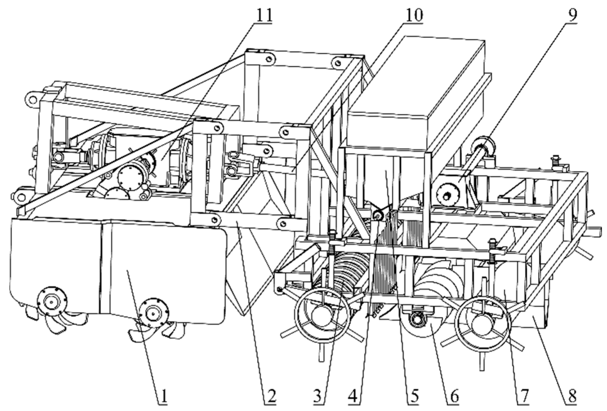
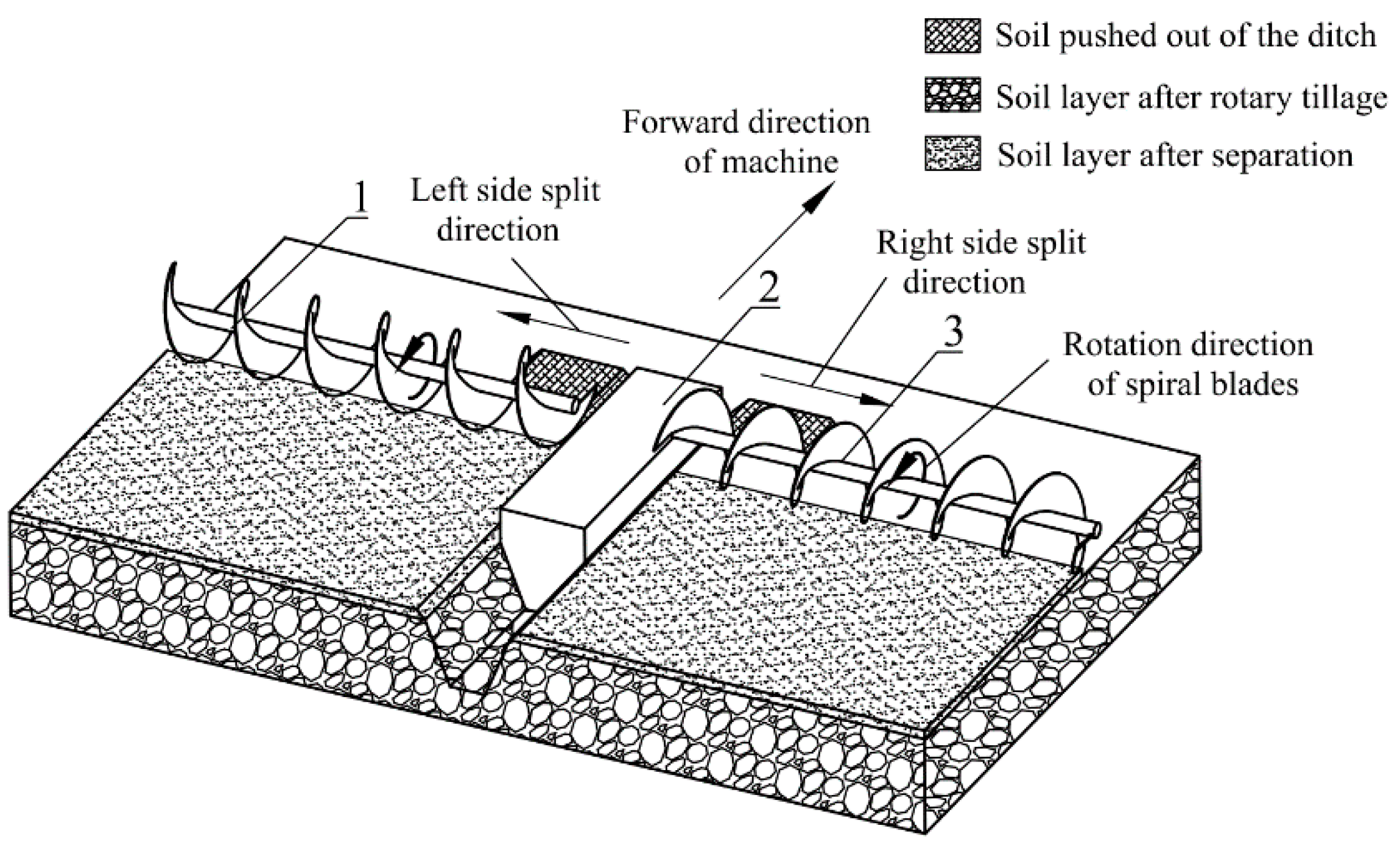
2.1. General Structure

As shown in Figure 1, the general structure of the compound planter is composed of biaxial rotary tillage mechanism, press grooving roller, seeder, ditcher, spiral soil separation mechanism (SSSM), and other components. The compound planter relates to the tractor through the three-point linkage, which can complete the processes of tillage and land preparation, sowing, soil covering and pressing, and ditching at one time.
The SSSM is composed of two spiral shafts symmetrically installed on the bearing seat of the frame, and the spiral blades on the two spiral shafts rotate in the opposite direction. The SSSM is an active moving part, its power comes from the intermediate transmission box of biaxial rotary tillage mechanism, and the power transmitted through universal joint and commutator. The ditcher is installed in the middle of the spiral shafts and firmly connected to the frame.
The working process of the SSSM is shown in Figure 2. As the ditcher moves forward, the soil in the middle is forced to move to both sides of the ditcher, and banded soil accumulate on both sides of the drainage ditch under shear and lifting action of the ditcher. When the SSSM passes through the banded soil, the soil is pushed to both sides by the conveying action of rotating spiral blades. This function can solve the problem of drainage ditch blockage by preventing the soil from falling back into the drainage ditch, and obtaining higher soil flatness.
In order to analyze the soil separating mechanization of spiral blade, two soil particles are taken below and in front of the spiral blades respectively (q1 and q2) for mechanical analysis and kinematic analysis. The analysis results are shown in Figure 3.
The soil particle q1 is affected by four forces from different directions, including the support force of the soil particle below (SN1), the support force and friction force of the blade (FN1, FS1) and its gravity (G). Under the action of the resultant force of above four forces (F1), q1 moves centrifugally at a speed of V1, and gradually moves away from the central axis of the helical blade.
When q1 is separated from the spiral blade, due to loss of resultant force of the blade to the soil particle (Fc1) and SN1, q1 finally falls to the ground under the action of G.
With the rotation and forward movement of the spiral blades, the soil particle q2 is affected by three forces from different directions, including the support force and friction force of the blade (FN2, FS2), and its gravity (G). Under the action of the resultant force of the above three forces (F2), q2 moves centrifugally at a speed of V2. VZ2 is the partial velocity of VZ in the vertical direction, and its velocity direction is downward. When q2 is separated from the spiral blade, it falls to the ground under the action of G.
In order to meet the requirements of continuous transportation of soil, the component speed direction of the soil in the y direction and the component force (FY) direction of the resultant force must be the same as the forward speed direction, as shown in Formula (1). This condition limits the relationship between the soil separation direction, the forward direction of the machine, the rotation direction of the spiral blade, and the helical direction of the spiral blade. As shown in Formula (1).
v | v | = F Y | F Y | = V Y | V Y |
The soil separation effect of spiral blade is affected by many factors, including pitch, rotation speed, forward speed, radius, and the embedded depth. While the working speed of the compound planter is relatively constant, which is 3 km h−1, and the radius of the spiral blade is not easy to change due to the influence of the structure of the machine. Therefore, this paper only studied the influence of the three factors of the embedded depth, pitch, and rotation speed of the spiral blade on the soil separation effect.

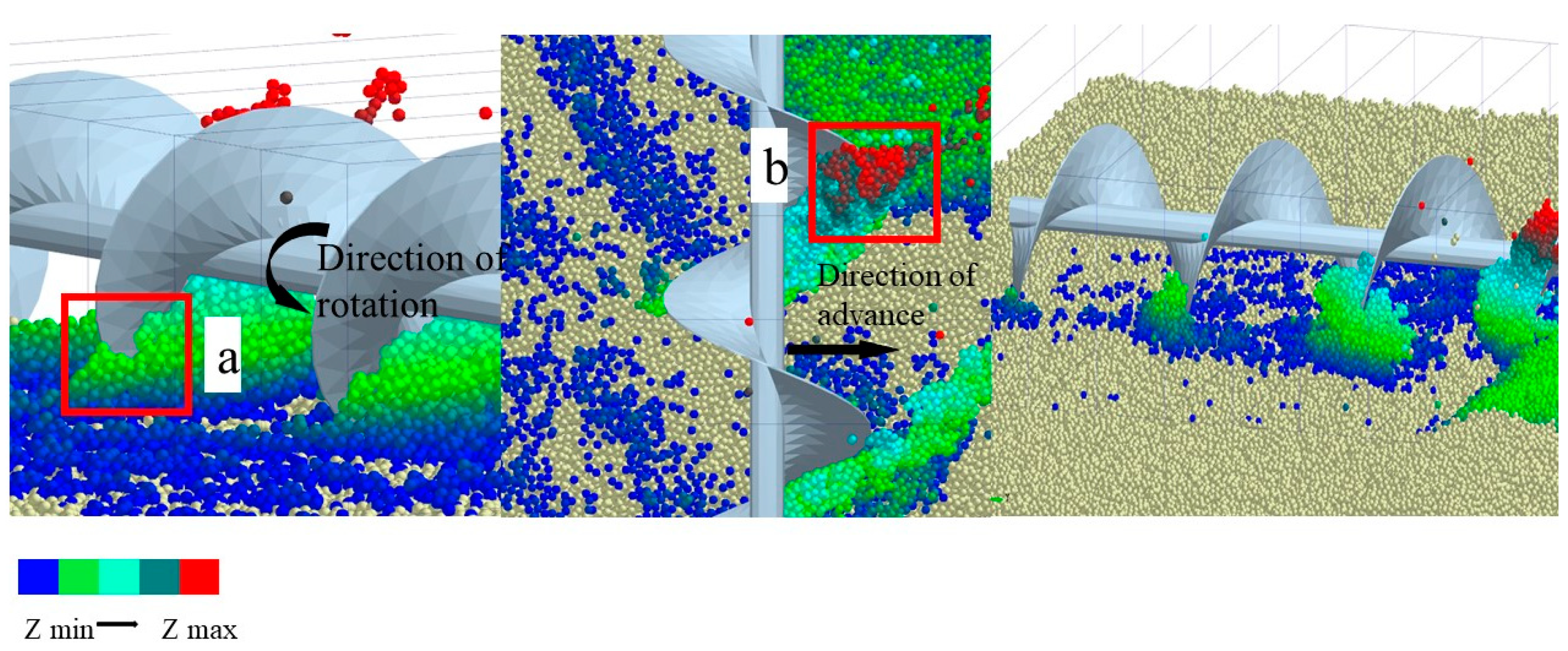
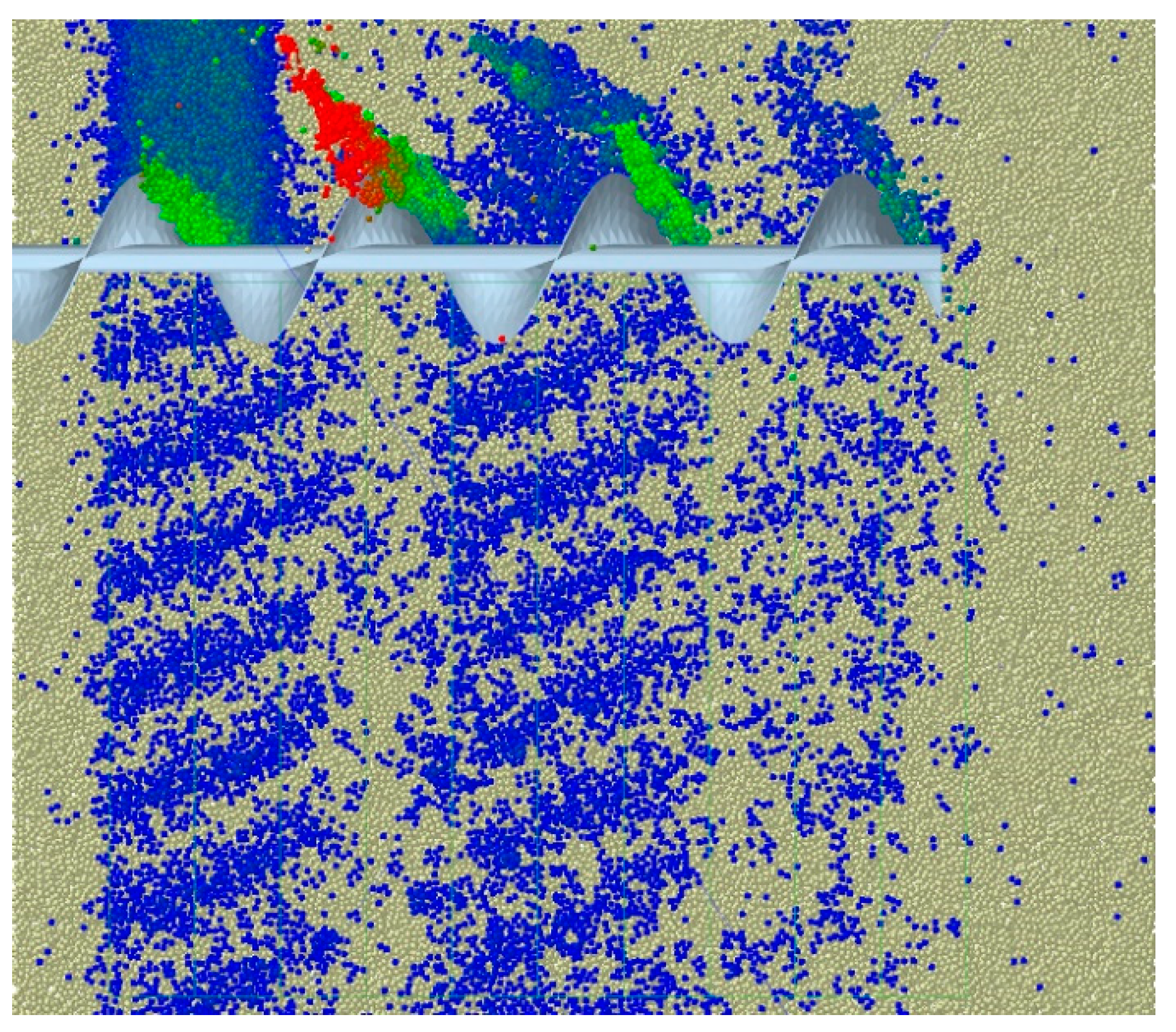
2.2. Discrete Element Simulation

In this paper, the operation process of SSSM were simulated by EDEM 2020 (DEM Solutions Ltd., Edinburgh, Scotland, UK) to analyze its soil-separating effect. Due to its symmetrical structure, the discrete element simulation can be carried out only on one side of the SSSM. The simulation model is shown in Figure 4. Similar to many researchers, spherical particles with a radius of 5 mm were used as soil particles in this study [17,19,20]. The soil model was divided into two layers (a, b), where layer a indicated the surface soil with size of 2500 mm × 1600 mm × 40 mm, and layer b indicated the banded soil accumulate on both sides of the drainage ditch with size of 2500 mm × 200 mm × 60 mm. The Hertz–Mindlin with JKR model was selected as the bonding model for the soil particles, and Hertz–Mindlin (no slip) was selected as the contact model between soil and spiral blade. The SSSM model was imported from SolidWorks, the length was 1200 mm, and the diameter of spiral blade was 240 mm. The soil was analyzed in the field test area (33°22′21.5″ N, 118°15′59.6″ E; clay) for the angle of the repose experiment (Figure 5) to determine the relevant parameters of the soil model [24,25,26,27,28,29,30,31,32], as shown in Table 1.
In order to analyze the influence of the embedded depth, pitch, and rotation speed of the spiral blade on the soil separation quality, three groups of single factor tests were designed to analyze the influence of each parameter on the soil separation distance and uniformity. The test parameters are shown in Table 2.
In the single factor test, the influence trend of three parameters on soil separation distance and uniformity can be obtained. In order to obtain the optimal parameters of target soil separation distance and uniformity, a central composite design was carried out for embedded depth, pitch, and rotation speed by using Design-Expert software (version 12). The level of test factors is shown in Table 3.

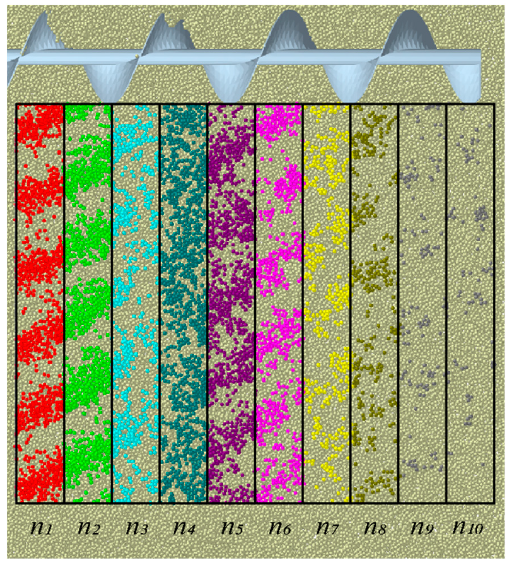
2.3. Soil Separation Quality Evaluation Index

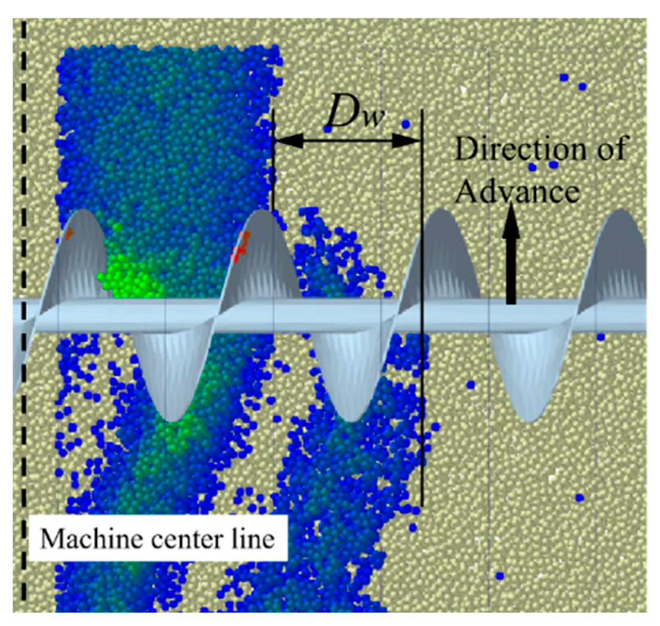
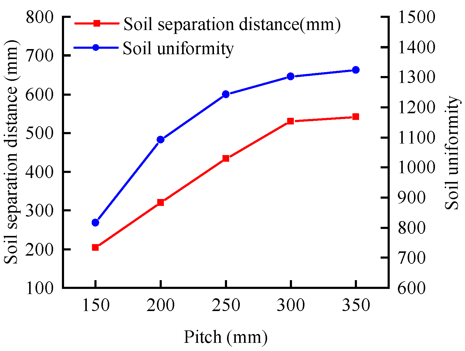
2.3.1. Soil Separation Distance

The soil separation distance DW is used to describe the maximum soil separation distance of the SSSM. As shown in Figure 6, the edge of the strip-shaped soil is the starting point, the outer edge of the soil after the operation of the soil divider is the end point, and the distance between the two edges is DW. Mark the surface soil particles and measure the distance.

2.3.2. Soil Uniformity

Soil uniformity E is used to describe the uniformity of soil distribution within the width of machines. The larger the value of E, the higher the uniformity of soil distribution. As shown in Figure 7, 10 grids were established in the stable soil division section with size of 1000 mm × 120 mm × 300 mm. The calculation formula of E is as follows:
{ n ¯ = i = 1 10 n i 10 U = i = 1 10 ( n i n ¯ ) 2 10 E = 2000 U
where ni (I = 1,2,···,10) is the number of soil particles in each grid derived from EDEM, U is the overall calculation standard deviation of ni, n ¯ is the average value of the number of soil particles in ten grids.

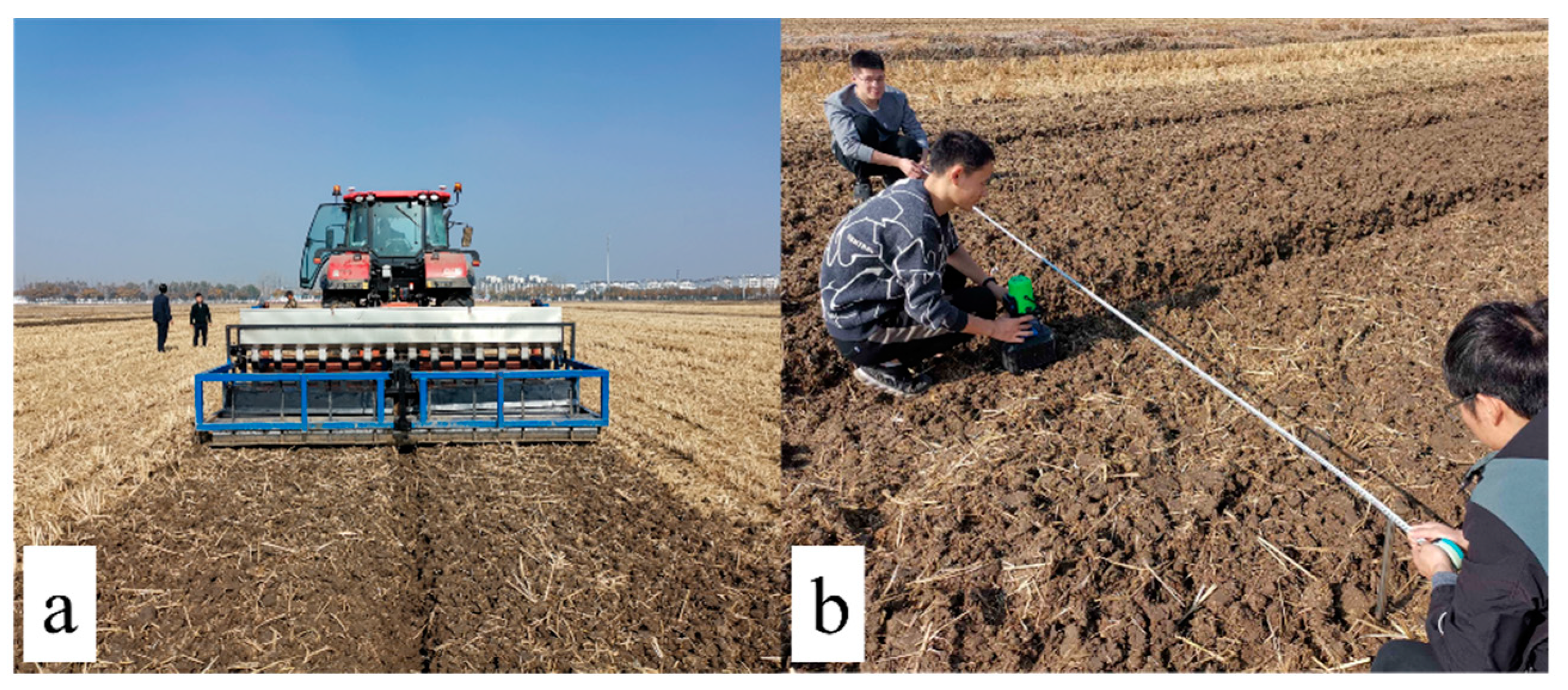
2.4. Field Experiment

On 19 November 2021, field experiment was carried out in Sihong County, Suqian City, Jiangsu Province (33°22′21.5″ N, 118°15′59.6″ E). The soil type in the experimental area was clay with a moisture content of 21.38%. The test equipment is shown in Figure 8a. The embedded depth, pitch, and rotation speed of spiral blade were 49 mm, 331 mm, and 318 r min−1 respectively (the optimal parameters obtained by the regression model).
In practical operation, the soil uniformity was reflected in the difference of field soil accumulation per unit distance in the direction of operation width. Due to the existence of repress roller, it was difficult to measure the soil accumulation after the operation of compound planter, and there were large errors. Considering that the soil type in the test area was clay and its compressibility was low, this characteristic will cause the area with large soil accumulation to be unable to maintain the same height as other areas after compaction, so the height difference of the soil after compaction was used to reflect the uniformity of soil division. The horizontal line was determined by a laser level (accuracy ± 1.5°), as shown in Figure 8b. The distance between the horizontal line and the surface soil was measured by a steel ruler, and the result was converted into the soil height value H. The starting point of the measurement is the edge of the drainage ditch, the measurement range is 1.5 m, the measurement interval is 10 cm, and the distance between the measurement point and the edge of the drainage ditch is DC. The average value was calculated after ten groups of data were randomly measured in the forward direction of the compound planter.

3. Results and Analysis

As shown in Figure 9, the soil particles move outward under the action of spiral blades, and the soil particles at area “a” and “b” were dispersed within the operation width by pushing and scattering of the blades respectively.

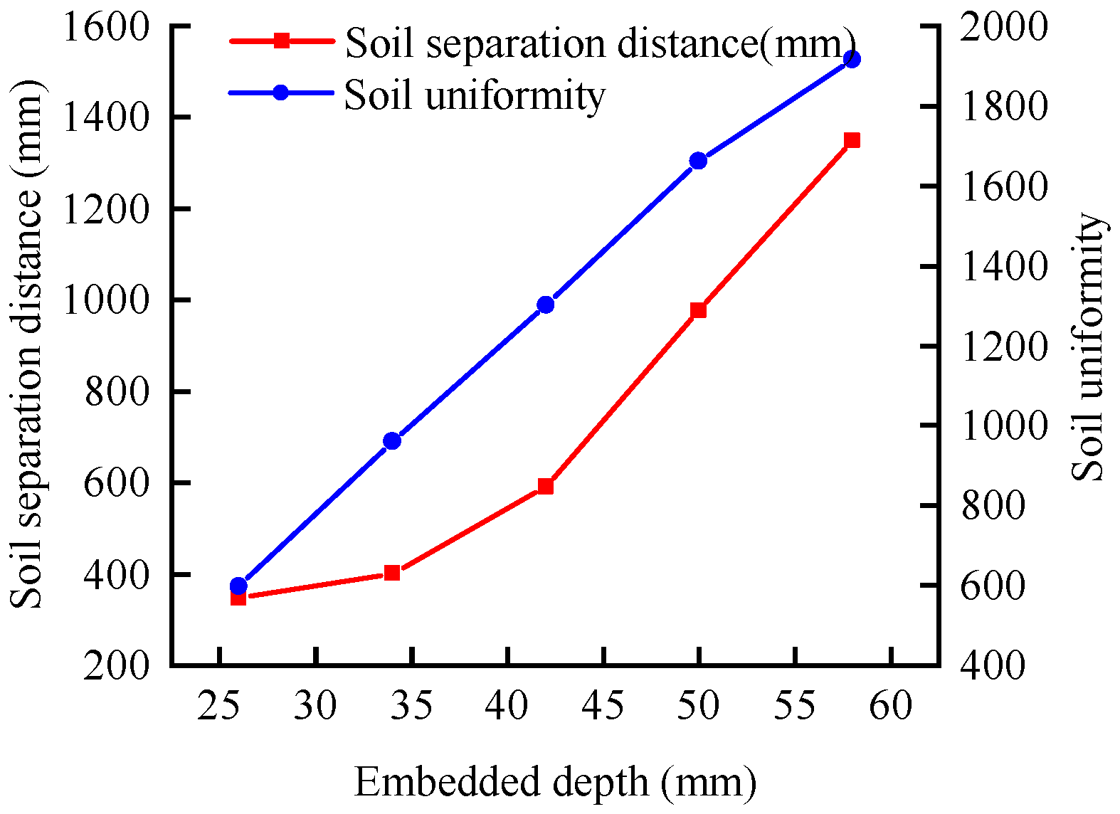
3.1. Single Factor Experiment

(1) Effects of rotation speed on soil separation distance and uniformity
Figure 10 shows the relationship curves between rotation speed and DW, E when the embedded depth was 42 mm and the pitch was 300 mm. When the rotation speed increased from 130 r min−1 to 410 r min−1, the soil separation distance increased from 254 mm to 956 mm, which increased by 702 mm. When the rotation speed was about 380 r min−1, the optimal soil separation distance was 900 mm, and the rotation speed was approximately linear with the separation distance. The soil uniformity increased by 765 from 710 to 1475. When the rotation speed increased from 130 r min−1 to 270 r min−1, the soil uniformity increased by 590. When the rotation speed increased from 270 r min−1 to 410 r min−1, the soil uniformity increased by 170, indicating that with the increase of rotation speed, the improvement of rotation speed on soil uniformity gradually weakened.
(2) Effects of pitch on soil separation distance and uniformity
Figure 11 shows the relationship curves between pitch and DW, E when the soil depth was 42 mm and the rotation speed was 270 r min−1. When the pitch increased from 150 mm to 350 mm, the soil separation distance increased from 204 mm to 542 mm, which increased by 338 mm. With the increased of pitch, the effect of pitch on the improvement of soil separation distance gradually weakened. This was because the helix angle of the spiral blade increased with the increase of the pitch, which made FX1 and FX2 decrease, thus reducing the push ability of the spiral blade to the x direction of the soil particles. The uniformity of soil separation increased from 815 to 1323, which increased by 508, similar to the effect of rotation speed on soil uniformity. With the increased of pitch, the improvement of pitch on soil uniformity gradually weakened. The above results showed that increasing the pitch can increase the soil separation distance and soil uniformity, but with the increased of pitch, the increase rate of soil separation distance and soil uniformity became slow.
(3) Effects of soil depth on soil separation distance and uniformity
Figure 12 shows the relationship curve of the embedded depth of the blade with the soil separation distance and the soil uniformity when the pitch was 300 mm and the rotation speed was 270 r min−1. When the embedded depth increased from 26 mm to 58 mm, the soil separation distance increased from 346 mm to 1350 mm, which increased by 1004 mm. When the embedded depth was about 48 mm, the optimal soil separation distance was 900 mm. With the increased of soil depth, the increase rate of soil separation distance gradually increased. This was because with the increase of the embedded depth, the volume of soil transported by spiral blades increased, and the contact time between soil particles and spiral blades increased, which increased the action time of FX1 and FX2. More contact time improved the pushing ability of the spiral blade to the soil particles in the x direction, and some soil particles were scattered outside the working width. The soil uniformity increased from 599 to 1915, which increased by 1316, and the embedded depth was approximately linear with the soil uniformity. The above results showed that increasing the embedded depth can effectively improve soil separation distance and uniformity.

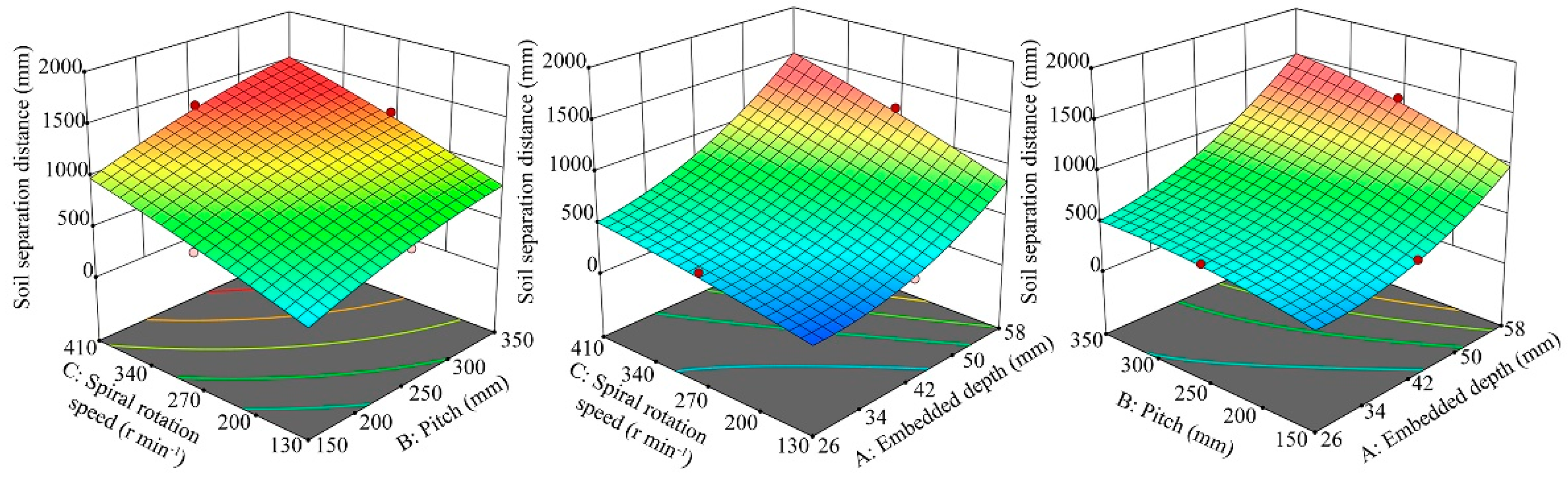
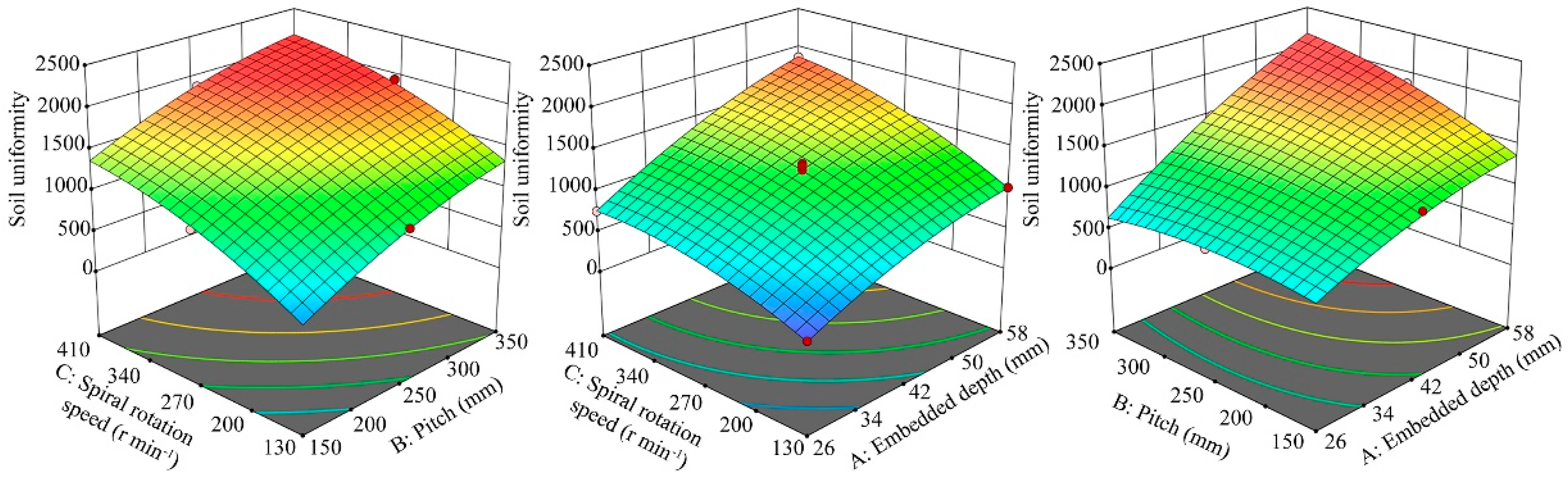
3.2. Multifactor Experiment

The experimental design and results of response surface analysis method are shown in Table 4. The quadratic polynomial regression model of soil separation distance and soil separation uniformity was obtained by Design-Expert software.
D w = 513.8 + 333 A + 165.88 B + 229.38 C + 83.5 AB + 90 AC + 21.25 BC + 172.72 A 2 60.03 B 2 22.02 C 2 E = 1237.4 + 464.5 A + 212.63 B + 342.13 C + 204.25 AB + 94.75 AC 20.5 BC 113.7 A 2 111.45 B 2 145.45 C 2
The variance analysis of the response values DW and E is shown in Table 5 and Table 6. The p-values of the two models are less than 0.01, indicating that the selected factors in the equation are extremely significant. The misfits are greater than 0.05, which are not significant.
Figure 13 shows the response surface analysis of the relationship between test factors and separation distance. The influence of the embedded depth and rotation speed on soil separation distance was greater than that of pitch, which was consistent with the p-values of the embedded depth (p < 0.0001), the rotation speed (p < 0.0001), and the pitch (p = 0.0004) in Table 5. With the increase of the embedded depth, rotation speed, and pitch, the soil separation distance increased. The greater the embedded depth and rotation speed, the greater the soil separation distance.
Figure 14 shows the response surface analysis of the relationship between test factors and soil uniformity. The embedded depth, pitch, and rotation speed had significant indigenous effects on soil uniformity. With the increase of the embedded depth, rotation speed, and pitch, soil uniformity increased significantly. The greater the embedded depth, the greater the increase of soil uniformity.
When the soil separation distance of the spiral blade is 900 mm, the soil accumulated on both sides of the drainage ditch covers the operation width of the SSSM, and this distance is the best soil separation distance. The response surface analysis shows that the requirement of soil separation distance could not be the condition of the best soil separation uniformity. With the increase of various test factors, the soil increases, but the excessive soil separation uniformity makes the soil separation distance much larger than the target soil separation distance. Therefore, it was necessary to improve the soil separation uniformity as far as possible under the condition of soil separation distance 900 mm.
The optimization equation was obtained by the Design-Expert software multiobjective optimization method with DW and E as the optimization objective function 4. The optimal parameters were obtained. Embedded depth was 49 mm, pitch was 331 mm, and rotation speed was 318 r min−1. The discrete element simulation model was established with the optimal parameters, the soil separation distance was 917 mm, the soil separation uniformity was 1728. Figure 15 shows the simulation results.
{ 26 < A < 58 150 < B < 350 130 < C < 410 D w = 900 max E

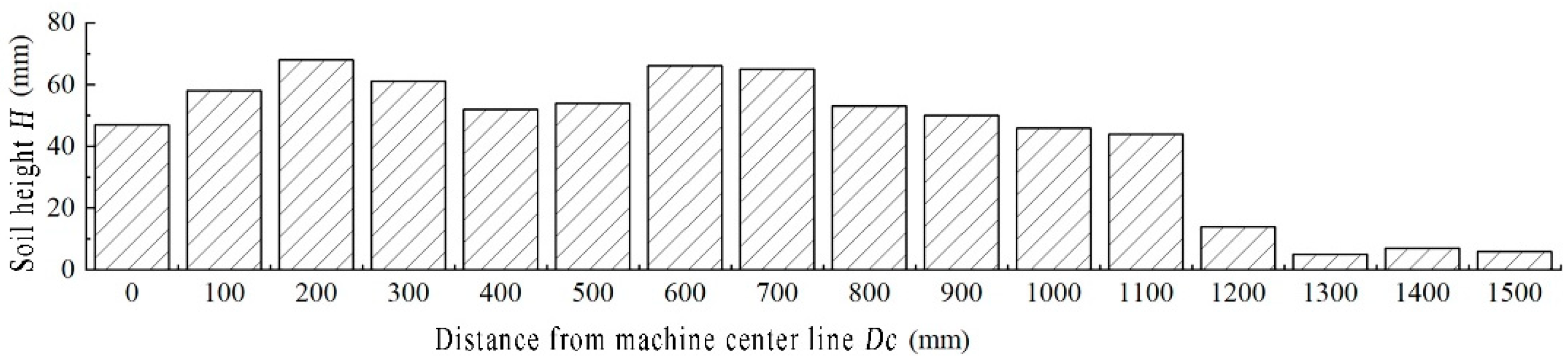
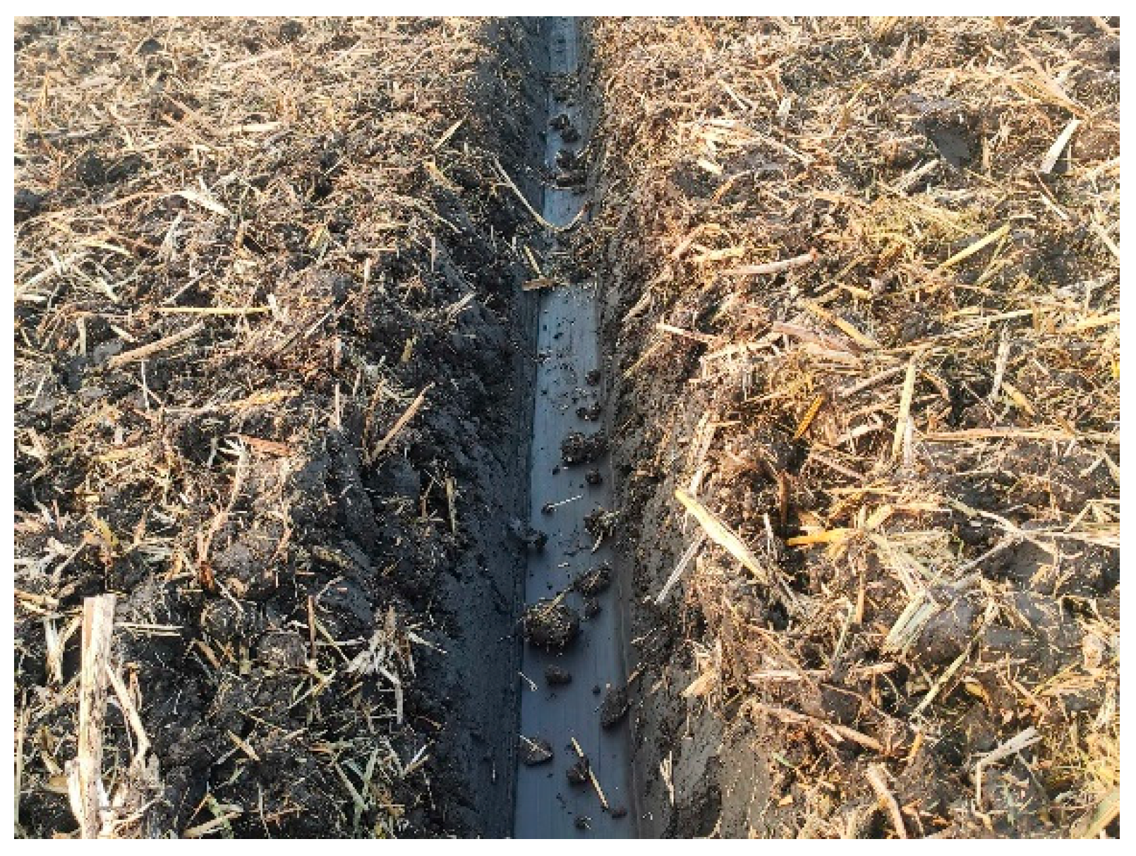
3.3. Field Experimental Results

The average value of ten groups of data in the field experiment is shown in Figure 16. The position where DC was equal to 0 mm was the edge of the drainage ditch, and the position where DC was equal to 200 mm was the edge line of the origin of soil separation distance measurement in the simulation test. Since H was higher in the range of DC from 0 to 1100 mm than that in the range of DC from 1200 to 1500 mm, the range of 200 to 1100 mm was the soil separation interval. The soil separation distance in the field test was about 900 mm, which was consistent with 917 mm in the simulation test. In the range of DC from 0 to 1100 mm, when DC = 200, the maximum H = 68 mm, when DC = 1100, the minimum H = 44 mm, and the height difference of H was 24 mm. Within this range, the standard deviation of H was 7.8 mm, the level of soil flatness was high, and there was no blockage of drainage ditch, as the Figure 17 shown.

4. Discussion

It is reported that the simplified or compound planting technological process has a positive impact on farming efficiency. Drainage ditches can drain surface waterlogging during wheat growing, especially in areas with excessive rainfall. However, considering the structure and operation characteristics of various ditching machines, the device for digging drainage ditch is not integrated in the general compound planter. Therefore, this study differed from previous ones dramatically. First, SSSM which can be integrated with compound planter was proposed. This device can complete the operation of opening drainage ditch and evenly disperse the accumulated soil. Second, the influence of the structural parameters of the SSSM on optimizing soil particle distribution was studied by discrete element method. The structural parameters have been optimized to achieve a better soil separating effect.
In this paper, Formula (1) was obtained through kinematic and dynamic analysis, which established the relationship between the soil separation direction, the forward direction of the machine, the rotation direction of the spiral blade, and the helical direction of the spiral blade. Yang et al. [33] designed a track filling assembly mounted on wheeled-tractor for paddy fields. The relationship between the soil separation direction, the forward direction of the machine, the rotation direction of the spiral blade, and the helical direction of the spiral blade of the device met Formula (1) was consistent with the research results of this paper. The best spiral blade parameters obtained in this paper were embedded depth = 49 mm, pitch = 331 mm, rotation speed = 318 r min−1. This result was not consistent with the study of Yang et al. (depth = 45 mm, pitch = 200 mm, rotation speed = 200 r min−1). This was due to the different characteristics of transported materials, transportation volume, forward speed of machines, and the helical direction of the spiral blade, etc. This study can provide a reference for the design of soil separation equipment using spiral soil separation device, and for the design of devices for conveying and leveling materials with spiral blades.
However, there are several limitations in this research. First, it lacks the support of wheat planting experiment. In fact, the effects of ditching and soil separation will affect the growth status and final yield of wheat. Second, there is a lack of research on soil structure parameters after soil separation, such as soil particle distribution, soil porosity, and water stable aggregates, etc. Further study is needed to judge the impact of ditching and soil separation on soil structure. In the future, we will focus on the effects of SSSM on wheat yield and soil structure parameters.

5. Conclusions

(1) The design of the SSSM solves the problems encountered in the compound planter ditching process, such as uneven soil, drainage ditch blockage. At the same time, the soil separation mechanism of spiral blades in the soil separation device was analyzed, and the stress analysis and kinematic analysis of the soil separation process were carried out.
(2) The discrete element simulation model of SSSM was established, and the evaluation indexes of soil separation distance and soil uniformity was established to evaluate the operation quality of SSSM, which laid the foundation for the parameter setting of SSSM.
(3) The single factor simulation test showed that there was an approximate linear relationship between the rotation speed and soil separation distance, but the increase of soil separation uniformity decreases with the increase of rotation speed. Increasing pitch can increase soil separation distance and soil separation uniformity. However, with the increase of pitch, the increase of soil separation distance and soil uniformity decreased. Increasing embedded depth can effectively improve soil separation distance and uniformity.
(4) The results of response surface analysis showed that with the increase of embedded depth, rotation speed, and pitch, soil separation distance and soil uniformity also increased. When the embedded depth and rotation speed increase, the soil separation distance also increases. Similarly, the greater the embedded depth, the greater the increase in soil uniformity.
(5) The quadratic regression model of soil separation quality was established, and the following optimization parameters were obtained: the embedded depth was 49 mm, the pitch was 331 mm, and the rotation speed was 318 r min−1. The optimized parameters were obtained in the field experiment. The soil separation distance was 900 mm, and the standard deviation of soil flatness was 7.8 mm, which was consistent with the simulation results, and there was no drainage ditch blockage.

Author Contributions

Conceptualization, L.H. and R.Z.; methodology, X.X. and J.Y.; software, L.H. and X.X.; validation, W.Y. and J.Y.; formal analysis, L.H.; investigation, W.Y.; resources, J.J. and X.X.; data curation, Y.Z.; writing—original draft preparation, W.Y.; writing—review and editing, J.J. and D.X.; visualization, Y.Z.; supervision, D.X.; funding acquisition, R.Z. All authors have read and agreed to the published version of the manuscript.

Funding

This research was funded by Yangzhou University Interdisciplinary Research Foundation for Crop Science Discipline of Targeted Support (yzuxk202007), the Key Research and Development Program of Jiangsu Province (BE2020319), Jiangsu Modern Agricultural Machinery Equipment and Technology Demonstration and Promotion Project (NJ2021-16), High-end Talent Support Program of Yangzhou University.

Institutional Review Board Statement

Not applicable.

Informed Consent Statement

Not applicable.

Data Availability Statement

Not applicable.

Conflicts of Interest

The authors declare no conflict of interest.

References

  1. Liu, H.; Xiong, W.; Mottaleb, K.A.; Krupnik, T.J.; Burgueño, J.; Pequeno, D.N.L.; Wu, W. Contrasting contributions of five factors to wheat yield growth in China by process-based and statistical models. Eur. J. Agron. 2021, 130, 126370. [Google Scholar] [CrossRef]
  2. Ren, A.-X.; Sun, M.; Wang, P.-R.; Xue, L.-Z.; Lei, M.-M.; Xue, J.-F.; Gao, Z.-Q.; Yang, Z.-P. Optimization of sowing date and seeding rate for high winter wheat yield based on pre-winter plant development and soil water usage in the Loess Plateau, China. J. Integr. Agric. 2019, 18, 33–42. [Google Scholar] [CrossRef]
  3. Chen, J.; Zheng, M.-J.; Pang, D.-W.; Yin, Y.-P.; Han, M.-M.; Li, Y.-X.; Luo, Y.-L.; Xu, X.; Li, Y.; Wang, Z.-L. Straw return and appropriate tillage method improve grain yield and nitrogen efficiency of winter wheat. J. Integr. Agric. 2017, 16, 1708–1719. [Google Scholar] [CrossRef] [Green Version]
  4. He, J.; Shi, Y.; Zhao, J.; Yu, Z. Strip rotary tillage with subsoiling increases winter wheat yield by alleviating leaf senescence and increasing grain filling. Crop J. 2020, 8, 327–340. [Google Scholar] [CrossRef]
  5. Xi, X.; Gao, W.; Gu, C.; Shi, Y.; Han, L.; Zhang, Y.; Zhang, B.; Zhang, R. Optimisation of no-tube seeding and its application in rice planting. Biosyst. Eng. 2021, 210, 115–128. [Google Scholar] [CrossRef]
  6. Xi, X.; Gu, C.; Shi, Y.; Zhao, Y.; Zhang, Y.; Zhang, Q.; Jin, Y.; Zhang, R. Design and experiment of no-tube seeder for wheat sowing. Soil Tillage Res. 2020, 204, 104724. [Google Scholar] [CrossRef]
  7. Wu, F.; Zhai, L.-C.; Xu, P.; Zhang, Z.-B.; Baillo, E.H.; Tolosa, L.N.; Kimotho, R.N.; Jia, X.-L.; Guo, H.-Q. Effects of deep vertical rotary tillage on the grain yield and resource use efficiency of winter wheat in the Huang-Huai-Hai Plain of China. J. Integr. Agric. 2021, 20, 593–605. [Google Scholar] [CrossRef]
  8. Zhang, C.; Liu, J.; Shang, J.; Cai, H. Capability of crop water content for revealing variability of winter wheat grain yield and soil moisture under limited irrigation. Sci. Total Environ. 2018, 631, 677–687. [Google Scholar] [CrossRef]
  9. Zhang, H.; Li, Y.; Meng, Y.-L.; Cao, N.; Li, D.-S.; Zhou, Z.-G.; Chen, B.-L.; Dou, F.-G. The effects of soil moisture and salinity as functions of groundwater depth on wheat growth and yield in coastal saline soils. J. Integr. Agric. 2019, 18, 2472–2482. [Google Scholar] [CrossRef]
  10. Wu, S.; Ren, J.; Chen, Z.; Yang, P.; Li, H. Soil moisture estimation based on the microwave scattering mechanism during different crop phenological periods in a winter wheat-producing region. J. Hydrol. 2020, 590, 125521. [Google Scholar] [CrossRef]
  11. Zhang, Y.; Wang, J.; Gong, S.; Xu, D.; Mo, Y.; Zhang, B. Straw mulching improves soil water content, increases flag leaf photosynthetic parameters and maintaines the yield of winter wheat with different irrigation amounts. Agric. Water Manag. 2021, 249, 106809. [Google Scholar] [CrossRef]
  12. Aikins, K.A.; Barr, J.B.; Antille, D.L.; Ucgul, M.; Jensen, T.A.; Desbiolles, J.M.A. Analysis of effect of bentleg opener geometry on performance in cohesive soil using the discrete element method. Biosyst. Eng. 2021, 209, 106–124. [Google Scholar] [CrossRef]
  13. Aikins, K.A.; Antille, D.L.; Ucgul, M.; Barr, J.B.; Jensen, T.A.; Desbiolles, J.M.A. Analysis of effects of operating speed and depth on bentleg opener performance in cohesive soil using the discrete element method. Comput. Electron. Agric. 2021, 187, 106236. [Google Scholar] [CrossRef]
  14. Barr, J.; Desbiolles, J.; Ucgul, M.; Fielke, J.M. Bentleg furrow opener performance analysis using the discrete element method. Biosyst. Eng. 2020, 189, 99–115. [Google Scholar] [CrossRef]
  15. Qin, K.; Ding, W.; Fang, Z.; Du, T.; Zhao, S. Design and parameter optimization of double disk opener mechanism for harvest ditch and stalk-disposing machine. Trans. Chin. Soc. Agric. Eng. 2017, 33, 27–35. [Google Scholar]
  16. Bao, P.; Wu, M.; Guan, C.; Luo, H.; He, Y.; Xiang, W. Design of plow-rotary style ditching and ridging device for rapeseed seeding. Trans. Chin. Soc. Agric. Eng. 2017, 33, 23–31. [Google Scholar]
  17. Aikins, K.A.; Ucgul, M.; Barr, J.B.; Jensen, T.A.; Antille, D.L.; Desbiolles, J.M.A. Determination of discrete element model parameters for a cohesive soil and validation through narrow point opener performance analysis. Soil Tillage Res. 2021, 213, 105123. [Google Scholar] [CrossRef]
  18. Barr, J.B.; Desbiolles, J.M.A.; Fielke, J.M.; Ucgul, M. Development and field evaluation of a high-speed no–till seeding system. Soil Tillage Res. 2019, 194, 104337. [Google Scholar] [CrossRef]
  19. Bahrami, M.; Naderi-Boldaji, M.; Ghanbarian, D.; Ucgul, M.; Keller, T. Simulation of plate sinkage in soil using discrete element modelling: Calibration of model parameters and experimental validation. Soil Tillage Res. 2020, 203, 104700. [Google Scholar] [CrossRef]
  20. Li, B.; Chen, Y.; Chen, J. Modeling of soil–claw interaction using the discrete element method (DEM). Soil Tillage Res. 2016, 158, 177–185. [Google Scholar] [CrossRef]
  21. Zhou, Y.; Wang, X.; Yu, Y. Research and Analysis of the Optimum Gap of the Screw Extraction Device Based on EDEM Software. J. Agric. Mech. Res. 2017, 39, 38–42. [Google Scholar]
  22. Owen, P.J.; Cleary, P.W. Prediction of screw conveyor performance using the Discrete Element Method (DEM). Powder Technol. 2009, 193, 274–288. [Google Scholar] [CrossRef]
  23. Pezo, M.; Pezo, L.; Jovanović, A.P.; Terzić, A.; Andrić, L.; Lončar, B.; Kojić, P. Discrete element model of particle transport and premixing action in modified screw conveyors. Powder Technol. 2018, 336, 255–264. [Google Scholar] [CrossRef]
  24. Müller, D.; Fimbinger, E.; Brand, C. Algorithm for the determination of the angle of repose in bulk material analysis. Powder Technol. 2021, 383, 598–605. [Google Scholar] [CrossRef]
  25. Asaf, Z.; Rubinstein, D.; Shmulevich, I. Determination of discrete element model parameters required for soil tillage. Soil Tillage Res. 2007, 92, 227–242. [Google Scholar] [CrossRef]
  26. Mak, J.; Chen, Y.; Sadek, M.A. Determining parameters of a discrete element model for soil–tool interaction. Soil Tillage Res. 2012, 118, 117–122. [Google Scholar] [CrossRef]
  27. Obermayr, M.; Vrettos, C.; Eberhard, P.; Däuwel, T. A discrete element model and its experimental validation for the prediction of draft forces in cohesive soil. J. Terramechanics 2014, 53, 93–104. [Google Scholar] [CrossRef]
  28. Horabik, J.; Molenda, M. Parameters and contact models for DEM simulations of agricultural granular materials: A review. Biosyst. Eng. 2016, 147, 206–225. [Google Scholar] [CrossRef]
  29. Obermayr, M.; Dressler, K.; Vrettos, C.; Eberhard, P. Prediction of draft forces in cohesionless soil with the Discrete Element Method. J. Terramechanics 2011, 48, 347–358. [Google Scholar] [CrossRef]
  30. Ucgul, M.; Fielke, J.M.; Saunders, C. Three-dimensional discrete element modelling of tillage: Determination of a suitable contact model and parameters for a cohesionless soil. Biosyst. Eng. 2014, 121, 105–117. [Google Scholar] [CrossRef]
  31. Wang, X.; Hu, H.; Wang, Q.; LI, H.; He, J.; Chen, W. Calibration Method of Soil Contact Characteristic Parameters Based on DEM Theory. Trans. Chin. Soc. Agric. Mach. 2017, 48, 78–85. [Google Scholar]
  32. Chen, C.; Quan, W.; Wu, M.; Zhang, W. Parameter optimization of vertical soil-filling hole-forming parts for rapeseed transplantation based on discrete element method. J. Hunan Agric. Univ. 2019, 45, 433–439. [Google Scholar]
  33. Yang, W.; Luo, X.; Wang, Z.; Zhang, M.; Zeng, S.; Zang, Y. Design and experiment of track filling assembly mounted on wheeled-tractor for paddy fields. Trans. Chin. Soc. Agric. Eng. 2016, 32, 26–31. [Google Scholar]
Figure 1. General structure of compound planter. 1. Biaxial rotary tillage mechanism. 2. Connecting rod. 3. press grooving roller. 4. Seeder. 5. Seed box. 6. Spiral soil separating mechanism. 7. Repress roller. 8. Ditcher. 9. Steering box. 10. Transmission shaft. 11. Intermediate transmission box.
Agriculture 12 00511 g001
Figure 2. Working process of SSSM. 1. Left spiral blades. 2. Ditching. 3. Right spiral blades.
Agriculture 12 00511 g002
Figure 3. Mechanical and kinematic analysis of soil particles. where, v is the forward speed of the compound planter, m s−1; ω is the rotation speed of spiral blade, r min−1; α is the spiral angle, rad; φ is the friction angle between soil particles and blades, rad; P is the tangent plane of the contact point between the spiral blade and soil particles; FS is the friction force of soil particles by helical blades, N; FN is the supporting force of soil particles by spiral blades, N; FC is the resultant force of leaves on soil particles, N; F is the resultant force on soil particles, N; FX, FY and FZ are the component force of soil particles in the transverse, forward and vertical directions, N; G is the gravity of soil particles, N; SN is the support of soil particles by the underlying soil, N; Ve is the implicated movement of soil particles, m s−1; Vr is the implicated movement of soil particles, m s−1; V is the absolute movement of soil particles, m s−1; VX, VY and VZ are the component velocity of soil particles in transverse, forward and vertical directions, m s−1.
Agriculture 12 00511 g003
Figure 4. Discrete element simulation model diagram.
Agriculture 12 00511 g004
Figure 5. (a,b) Angle of repose experiment of soil.
Agriculture 12 00511 g005
Figure 6. Evaluation index of soil separation distance.
Agriculture 12 00511 g006
Figure 7. Evaluation index of soil uniformity.
Agriculture 12 00511 g007
Figure 8. Diagram of test equipment and test site. (a) test equipment. (b) test site.
Agriculture 12 00511 g008
Figure 9. Soil separating process. (a) soil particles below the spiral blades. (b) soil particles in front of the spiral blades.
Agriculture 12 00511 g009
Figure 10. Relationship curves between rotation speed and DW, E.
Agriculture 12 00511 g010
Figure 11. Relationship curves between pitch and DW, E.
Agriculture 12 00511 g011
Figure 12. Relationship curves between embedded depth and DW, E.
Agriculture 12 00511 g012
Figure 13. Response surface analysis of the relationship between test factors and separation distance.
Agriculture 12 00511 g013
Figure 14. Response surface analysis of the relationship between test factors and soil uniformity.
Agriculture 12 00511 g014
Figure 15. Simulation results after optimizing parameters of spiral soil separating device.
Agriculture 12 00511 g015
Figure 16. Field test results.
Agriculture 12 00511 g016
Figure 17. Drainage ditch.
Agriculture 12 00511 g017
Table 1. Soil parameters for simulation.
ParametersValues
Soil Poisson’s ratio0.38
Soil density (kg m−3)2680
Soil shear modulus1.2 × 106
Recovery coefficient between soil particles0.31
Static friction factor between soil particles0.77
Dynamic friction coefficient between soil particles0.08
Steel Poisson’s ratio0.3
Steel density (kg m−3)7850
Shear modulus of steel7 × 1010
Recovery coefficient between soil particles and steel0.3
Static friction factor between soil particles and steel0.36
Dynamic friction coefficient between soil particles and steel0.08
Surface energy (J m−3)6.1
Table 2. Single factor experimental design.
GroupTest Factor
Embedded Depth
(mm)
Pitch (mm)Spiral Rotation Speed
(r min−1)
142300130, 200, 270, 340, 410
242150, 200, 250, 300, 350270
326, 34, 42, 50, 58300270
Table 3. Experimental factors codes.
Test FactorSymbolTest Level
−101
Embedded depth/(mm)A264258
Pitch/(mm)B150250350
Spiral rotation speed/(r min−1)C130270410
Table 4. Response surface analysis test design and results.
Test NumberFactorResponse Value
Embedded DepthPitchSpiral Rotary SpeedSoil Separation Distance (mm)Soil Uniformity
1−1−10170494
20−1−1132442
3−110428597
40005201243
51−106581019
60004431324
70004681152
80−114931180
90117741478
10−101493757
110005621294
12−10−1159275
1310−16561010
140005761174
1501−1328822
1610113501871
1711012501939
Table 5. Variance analysis of quadratic term model of soil separation distance.
Error Source Sum of Squares
(×105)
Freedom Mean Square
(×105)
F
Value
p
Value
Model 17.2891.9236.24<0.0001 ***
A 8.8718.87167.47<0.0001 ***
B 2.2012.2041.550.0004 ***
C 4.2114.2179.46<0.0001 ***
AB 0.2810.285.270.0554
C 0.3210.326.120.0426 *
BC 0.0210.020.340.5776
1.2611.2623.710.0018 **
0.1510.152.860.1344
0.0210.020.390.5543
Residual 0.3770.05
Lack of Fit 0.2430.082.370.2113
Pure Error 0.1340.03
Total 17.6516
R2 = 0.979, Adjusted R2 = 0.9520, Predicted R2 = 0.7730, Adeq Precision = 22.5568
Note: *, ** and *** indicate significant difference at p < 0.05, p < 0.01 and p < 0.001 levels, respectively.
Table 6. Variance analysis of quadratic term model of soil uniformity.
Error SourceSum of Squares
(×105)
FreedomMean Square
(×105)
F
Value
p
Value
Model34.4793.8371.89<0.0001 ***
A17.26117.26324.01<0.0001 ***
B3.6213.6267.89<0.0001 ***
C9.3619.36175.77<0.0001 ***
AB1.6711.6731.320.0008 ***
C0.3610.366.740.0356
BC0.0210.020.320.5918
0.5410.5410.220.0151 *
0.5210.529.820.0165 *
0.8910.8916.720.0046 **
Residual0.3770.05
Lack of Fit0.1530.050.920.5069
Pure Error0.2240.06
Total34.8416
R2 = 0.9893, Adjusted R2 = 0.9755, Predicted R2 = 0.9201, Adeq Precision = 29.0687
Note: *, ** and *** indicate significant difference at p < 0.05, p < 0.01 and p < 0.001 levels, respectively.
Publisher’s Note: MDPI stays neutral with regard to jurisdictional claims in published maps and institutional affiliations.

