Article

Design and Experiment of Anti-Blocking Components for Shallow Stubble Clearing Based on Soil Bin Test

School of Agricultural Engineering and Food Science, Shandong University of Technology, Zibo 255049, China
*
Author to whom correspondence should be addressed.
Agriculture 2022, 12(10), 1728; https://doi.org/10.3390/agriculture12101728
Submission received: 23 September 2022 / Revised: 15 October 2022 / Accepted: 17 October 2022 / Published: 19 October 2022
(This article belongs to the Topic Innovation and Solution for Sustainable Agriculture)

Abstract

:
In response to the problems of excessive wheat stubble blocking the opener during corn seeding in wheat–corn double cropping areas, an active-strip stubble removal method was proposed under the premise of conservation tillage. Firstly, the effects of two conventional rotary blade structures (inward and outward) on the stubble-cleaning effect and power consumption were studied under five rotary speeds (400, 500, 600, 700, 800 rpm). The results show that when the rotary speed was 400–600 rpm, the outward structure of the rotary blade was more suitable for stubble cleaning. Then, a torque sensor and a six-component force sensor were applied to the soil bin test platform to measure the relative data of four oblique angles (0°, 15°, 22.5°, 30°) on the stubble-cleaning effect, seedbed parameters, and power consumption at three rotary speeds (400, 500, 600 rpm). The results show that the straw residue on the seedbed was effectively reduced when increasing the oblique angle and rotary speed. Moreover, the quality parameters of the seedbed were improved and the power consumption was reduced when reducing the oblique angle and rotary speed. When the rotary speed was 400–500 rpm, the difference between the vertical resistance and lateral resistance was relatively small, while the difference between the horizontal resistance was large.

1. Introduction

The Huang-Huai-Hai summer corn area is the largest concentrated corn production area and the main double cropping area of wheat–corn in China, The treatment methods of wheat straw are mainly high stubble mulching, crushing, returning, and collecting bales. Problems exist in the case of straw returning, such as large amounts of wheat straw mulching, more stubble, uneven stubble cutting, and a poor straw-crushing effect, which creates trouble for corn seeding [1]. The existing small and medium-sized corn seeders mostly adopt hoe and disc openers; excessive wheat straw will lead to the blockage of the openers [2]. In addition, wheat straw, wheat bran, and weeds covering the corn seeding belt will increase pests and diseases of corn [3]. In order to solve the above problems, a lot of research about no-tillage had been carried out in China.
The anti-blocking technology of foreign no-till seeders in other regions focuses on passive anti-blocking, mainly a disc opener and claw grass wheel [4,5], which is not applicable to small and light seeders in the Huang-Huai-Hai area in China. The anti-blocking technologies of domestic no-till seeders are divided into active and passive types in China. The passive types are mainly composed of grass-guide rollers [2] and claw-grass wheels [6,7], and the anti-blocking effect is not significant, when the straw coverage is large. The active anti-blocking device is installed in the front end of the furrow opener of the seeder with the rotary blade, stubble cutter, crushing blade, and vertical drive rake used in the secondary crushing wheat-seeding operation [8]. The rotary tillage anti-blocking technology [9,10,11] is often used for the treatment of corn seeding in wheat straw fields. Gu F.W. [12] designed an active no-tillage anti-blocking device based on the idea of “clean area planting” when the wheat straw coverage was 1.14 kg/m2. The straw on the surface of the area to be sown was crushed and collected. After pushing and lifting, it was scattered to the back end to realize the cleaning of the seedling belt. Jiang J.L. [13] put forward the cutting scheme of the combined operation of supported power cutting and passive disc-soil breaking, and designed a double cutter disc-power-cutting device to ensure the traffic ability of corn no-tillage planter when the wheat straw coverage is large. Gao N.N. [2] developed a rotary drum-type anti-blocking mechanism to solve the problems of heavy wheat straw and residue. The mechanism was mounted in front of each opener shank of the corn planter and the drum was rotated driven by a ground wheel at a certain speed. The above research shows that the active-strip tillage is more suitable for the Huang-Huai-Hai summer corn area in China when the amount of straw is large. However, difficulties exist for the existing strip tillage to achieve low power consumption and low dynamic soil under the premise of conservation tillage. The purpose of the stubble-clearing and anti-blocking device is to achieve an ideal seed bed. However, few studies focused on the stubble-clearing effect, seedbed parameters, and power consumption of equipment under strip farming conditions. Therefore, a shallow rotary-strip-tillage stubble-cleaning method was proposed in this paper to solve the problems existing in corn no-tillage sowing, which can be applied to the situation of a large mulching amount of straw.
The design thought is described as follows. Firstly, through the comparative analysis of the stubble-cleaning effect and power consumption of the inward and outward movement of the upright tillage blade, it is determined that the outward installation is more suitable for the stubble-cleaning device. Secondly, the oblique shallow rotary tillage is realized by changing the oblique angle of the upright outward device, and the optimal working parameters are determined according to the stubble-clearing effect, the seedbed parameters, and the power consumption of the machine. The seedbed parameters mainly include the soil-disturbance coefficient, furrow shape, dynamic soil rate (≤40%), furrow depth, soil-backfill rate, etc. The dynamic soil rate is the degree of soil movement in conservation tillage and in less-tillage sowing operation, which is related to the surface soil movement width and working width. Thirdly, in order to further reflect the working performance of the anti-blocking device, the soil-disturbance coefficient and soil-backfill rate are used as other indicators of seedbed parameters.
In the details of the selection of the experimental design parameters, the main design basis of the device was based on the research of Kong L.D. [14], in which was shown that under specific conditions, the specific power consumption of rotary tillage can reach the minimum value, and the power consumption of inclined rotary tillage can be effectively reduced compared with that of normal rotary tillage when the oblique angle is 15°−20°. Gao J.M. [15] proposed oblique submerged soil reverse rotary tillage to realize the function of low energy consumption and short-knife deep rotary tillage. Chen H.T. [16] designed an active anti-blocking device with inclined blade teeth, the oblique angle between the vertical surface of the rotary shaft of the stubble-cleaning blade and the forward direction of the machine was 20°, which effectively reduced the amount of corn residues thrown to the sowing belt. Fang H.M. [17,18,19] analyzed the force and displacement of straw and soil during rotary tillage operation with a forward speed of 0.22 m/s, tillage depth of 100 mm, and rotary speed of 77–280 rpm. The development of conservation farming implemented for two-wheel tractors (power tillers) in Cambodia, Lao PDR, and Bangladesh produced a report. This project aimed to build the capacity of farmers through the development of seed drills for two-wheel tractors, based on existing prototypes, and the development of both tined-seed drills and rotary-tillage-seed drills [20]. Matin M.A. [21,22] studied the influence of three blade configurations (conventional, half width, and straight leaf) on the ridge and furrow seedbed parameters of strip tillage at four speeds (125, 250, 375 and 500 rpm) and compared and analyzed the seedbed parameters through four different blade chamfers, the soil-backfill rate, soil-tillage depth, and the volume and shape of the furrow, as well as the relevant ridge and furrow parameters of the seedbed which should be considered in strip rotary tillage.

2. Materials and Methods

2.1. Test Equipment and Materials

In this study, the test was carried out in the soil bin (Figure 1). The bench device was fixed to the trolley. The trolley provided a constant forward speed and accurate working depth for the test device. The motor rotary speed could be adjusted within the range of 0–2000 rpm through the frequency converter to provide the cutter shaft with the required speed for operation. The angle adjustment device realized different blade oblique angles within the range of 0–45° through the universal joint coupling. During the test, the working torque and rotary speed were transmitted to M400 software through dynamic torque sensor HCNJ-101 (accuracy ±0.5%, torque range 0 ± 50 N·m, rotary speed range 0–3000 rpm) and were recorded by dual signal conversion module MKMN-2 in real time. The output frequency of the torque sensor and six-component force sensor was 10 Hz.

2.1.1. Soil Preparation

The original sandy loam was adopted in the soil bin soil, which is the typical soil of maize planting area in most parts of the Huang-Huai-Hai region in China. Before tillage, the soil was fully irrigated, and rotary tillage was carried out when the soil layer could be cultivated. The soil tillage layer was compacted and leveled by the hoe shovel and compaction device of the trolley. The water content and soil hardness of the tillage layer were measured by the soil moisture meter (Germany STEPS3000) and the soil compaction meter (TJS-450 G), respectively. During the test, to measure the soil hardness and water content, soil data samples were randomly collected from three points in the forward direction of the device and the average values were calculated. The measurement results are as follows: when the soil layer was 0–5 cm depth, the average water content of the soil was 3.45% and the soil compactness was 2.5 MPa; when the soil layer was 5–10 cm depth, the average water content of the soil was 9.08% and the soil compactness was 3.1 Mpa.

2.1.2. Straw Treatment

Wheat plants at harvest time without other treatment after ear removal were used as straw. During the test, the moisture content of wheat straw (7.24%) was less than that at field harvest due to indoor prevention. Before the start of the soil bin test, the straw was evenly laid on the surface of the soil layer, and the straw coverage was 0.5 kg/m2. The coverage of wheat stubble met the requirements of the performance test index of the no-tillage (less-tillage) planter in the Huang-Huai-Hai region in China.

2.2. Test Contents and Methods

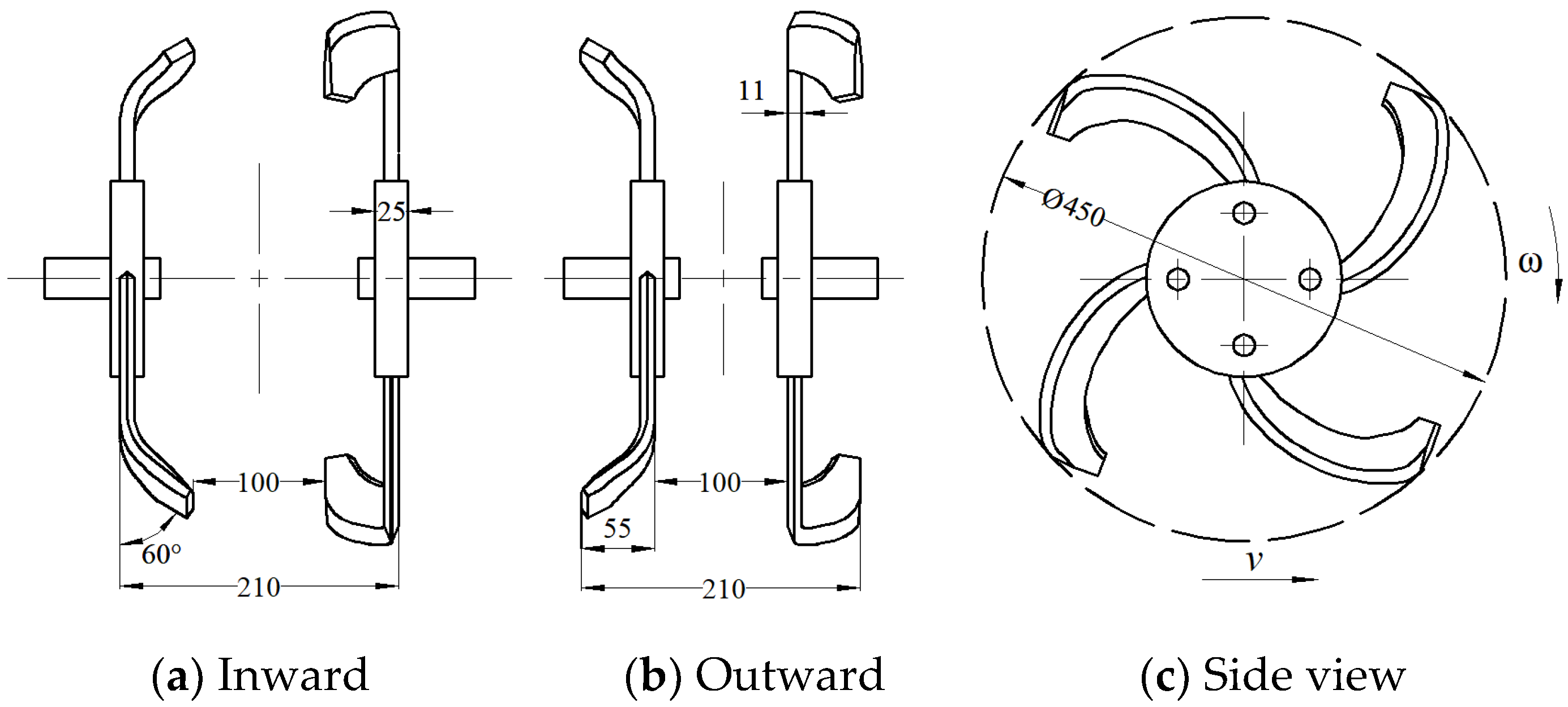
2.2.1. Upright Shallow Rotary Stubble Cleaning

In this test, the rotary tiller (IT225) was used. The limiting device on the cutter head enabled the two rotary tiller to be installed at 180° and the cutter head diameter was 200 mm. The rotary radius of the blade was 225 mm, the working width was 50 mm, and the blade thickness was 2 mm (Figure 2). The width of stubble clearing was 210 mm, and the stubble-clearing spacing between the two groups of tillers was 100 mm. The soil bin test was carried out by two arrangement modes of the blade, inward (Figure 2a) and outward (Figure 2b). During the test, the forward speed of the machine was 1.67 m/s, the depth of tillage was 50 mm, and the rotary speeds were 400, 500, 600, 700 and 800 rpm, respectively. The soil and straw throwing process was recorded by high-speed camera technology (the high-speed camera equipment was an industrial camera of OSG030-815UM) from the side and forward directions of the tiller and the best installation method was determined.

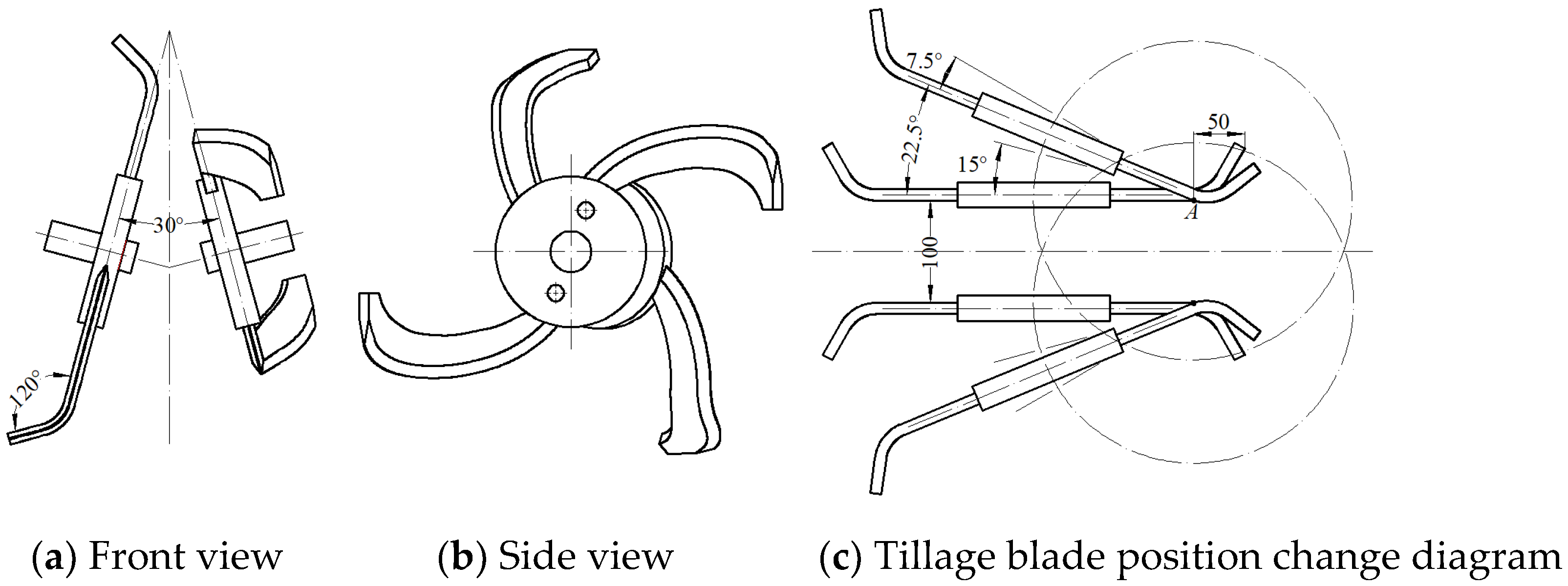
2.2.2. Oblique Shallow Rotary Stubble Cleaning

Existing studies have shown that oblique rotary tillage can effectively reduce power consumption under specific conditions. In addition, the wheat stubble will be deformed after being subjected to external forces during the no-tillage seeding of corn, the stubble that has not been uprooted is easy to rebind, and the straw on the residual surface is back-filled after being removed from the seedling belt. Oblique stubble clearing can increase the amount of side-throwing. The structure of the oblique shallow rotary stubble clearing is shown in Figure 3. On the basis of not keeping the original structural parameters of the rotary blade, the stubble contact area (cutting width) and the stubble-cutting angle were increased. The cutter shaft drove the rotary blade, and the slewing plane of the rotary blade had a certain angle with the forward direction of the machine. During stubble clearing, the blade edge contacted the straw and soil in sequence according to the distance from the center of the blade shaft from near to far along with cutting and removing away the straw and weeds covering the ground. At the same time, part of the stubble was thrown laterally to the side of the seedling belt and shallow rotary tillage of the seedling belt was realized finally. Part of the stubble was thrown laterally to the side of the seedling belt, and the shallow rotary tillage of the seedling belt was realized. According to the existing theoretical analysis, the stubble-clearing width is related to the tilt angle of the blade, the distance between the two groups of tillage blades without stubble clearing, and the tillage depth [23]. In order to ensure that the distance between the two groups of tillage knives remained at 100 mm, the center point of the tillage blade shaft needed to move on the circumference with A as the center point (Figure 3c). The oblique angle and rotary speed were tested by setting the amount of stubble straw, seedbed parameters, and power consumption as evaluation indicators. The test conditions were set as follows: the forward speed of the trolley was 1.67 m/s, the tillage depth was 50 mm, the oblique angle was 0° (control group), 15°, 22.5°, 30°, respectively, and the rotation speed of the cutter shaft was 400 rpm, 500 rpm, and 600 rpm, respectively.

3. Test Data Collection and Processing

3.1. Determination of Residual Straw

The straw floating on the surface was collected in the test area (width 1.5 m × length 5 m) after a single test was completed, the straw buried in the soil layer was ignored, the total mass of the remaining straw was weighed, and the stubble-cleaning rate [24] was calculated. The calculation formula of straw cleaning rate is as follows:
P c = C C 1 C × 100 %
where Pc is the stubble-cleaning rate, %. C1 is the remaining straw mass in the measurement area, kg. C is the total mass of the original straw in the measurement area, kg.

3.2. Seedbed Parameters

The parameters of the seedbed mainly included the soil-disturbance coefficient, furrow shape, dynamic soil rate (≤40%) [24], furrow depth, soil-backfill rate, etc. The tillage depth remained unchanged in the working process. Three cross sections of the anti-blocking device were selected at random from the working width in the test area [21], and the furrow shape was drawn with cardboard at the cross section. To facilitate the calculation of the ditch shape area, the uneven area on the inner side of the ditch shape during the measurement was ignored. Moreover, the cross section area of the remaining materials was approximated, and the soil-disturbance coefficient of the device was finally obtained. Then, the soil in the furrow was taken out to calculate the soil-backfill rate afterwards, and the depth of the lowest point from the surface was measured. The formulas of the soil-disturbance coefficient and dynamic soil rate were as follow:
r = S S 1 S × 100 %
where r is the soil-disturbance coefficient, %. S is the cross-sectional area of the theoretical tillage depth to the surface width before tillage, mm2. S1 is the cross-sectional area from actual tillage depth to surface width after tillage, mm2
D = k w × 100 %
where D is the dynamic soil rate, %. k is width of furrow after tillage, mm. w is width of planted seedling strip, mm, and the value is 600.

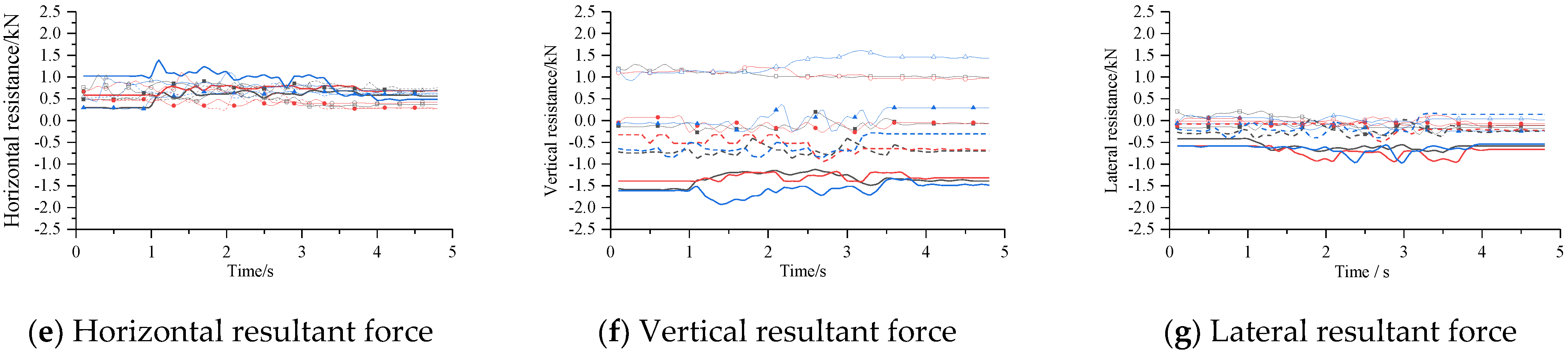
3.3. Power Consumption and Force Measurement

The power consumption of the blade could be calculated in the whole working process according to the relationship between the rotary speed, torque, and power consumption, as well as the output data of the dynamic torque sensor. At the same time, the horizontal force, vertical force, and lateral force of the blade-working processes were obtained by the six-component force device. The power consumption can be calculated as follows:
P = T n 9550
where P is the power consumption of the tillage blade, kW. T is the average torque during operation, N·m. n is the rotary speed of the blade during operation, r/min.

4. Test Results and Analysis

4.1. Shallow Rotary Stubble-Cleaning Performance Analysis

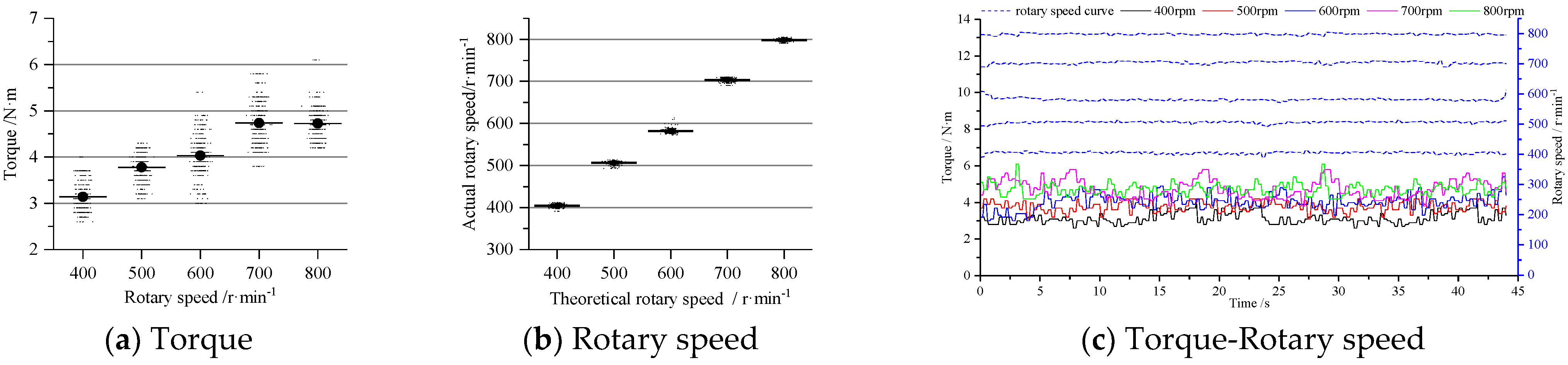
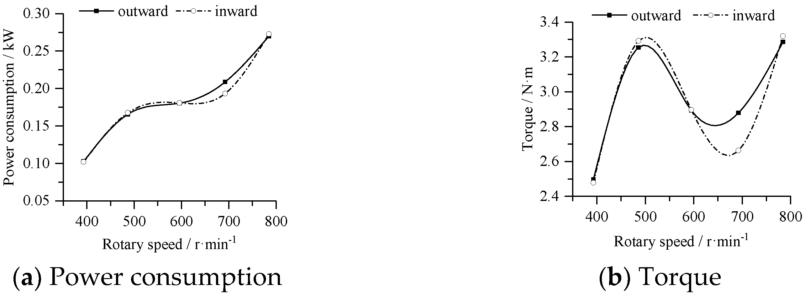
4.1.1. Rotary Speed and Torque Analysis

The phase angle is an important parameter to characterize the cutting position. When the blade was at different phase angles, the contact state between the blade and the soil was different, and the force on the blade was also different. Figure 4 and Figure 5 show the torque and speed changes of the tillage blade when it was installed inward and outward, respectively. From Figure 4, it could be seen that when the soil bin test was conducted at a certain forward speed, the torque of the tillage blade increased with the increase of the rotary speed (Figure 4c). When the rotary speed was in a certain range, the torque of the blade changed little. Due to the error in the signal transmission process, some individual data errors were relatively large. According to the test data, the scatter diagram of the torque speed was generated. It can be seen from Figure 4a that the torque of the blade was small and the torque variation range was not large when the speed was 400–500 rpm. When the rotary speed was 600–800 rpm, the torque error range of the blade was large.
It can be seen from Figure 4a,b that the torque of the output shaft was relatively stable when the rotary speed points with large errors were removed. Moreover, the torque of the tillage blade was small and the range of the torque change was not large when the rotary speed was 400 rpm, 500 rpm, and 600 rpm in the whole movement process. It can be seen from Figure 5c that the torque value of the power output shaft changed periodically during the rotation of the tillage blade. In the whole movement process, the torque increased with the decrease of rotary speed when the tillage blade encountered greater resistance. The torque changed little after the movement was stable in the end.

4.1.2. Subsubsection

According to Formula (4), the power consumption values of two groups of tillage blades in the working cycle were obtained. It can be seen from Figure 6a that the power consumption increased with the increase of the rotary speed. When the rotary speed was 400–600 rpm and 800 rpm, the power consumption values of the inward and outward mounting of the tillage blade had little difference. When the speed was 700 rpm, the power consumption with the outward type was significantly higher than that with the inward type. It can be seen from Figure 6b that when the speed reached 700 rpm, the torque with the outward type was obviously greater than that with the inward type, along with little difference of the torque values in other rotary speed ranges.

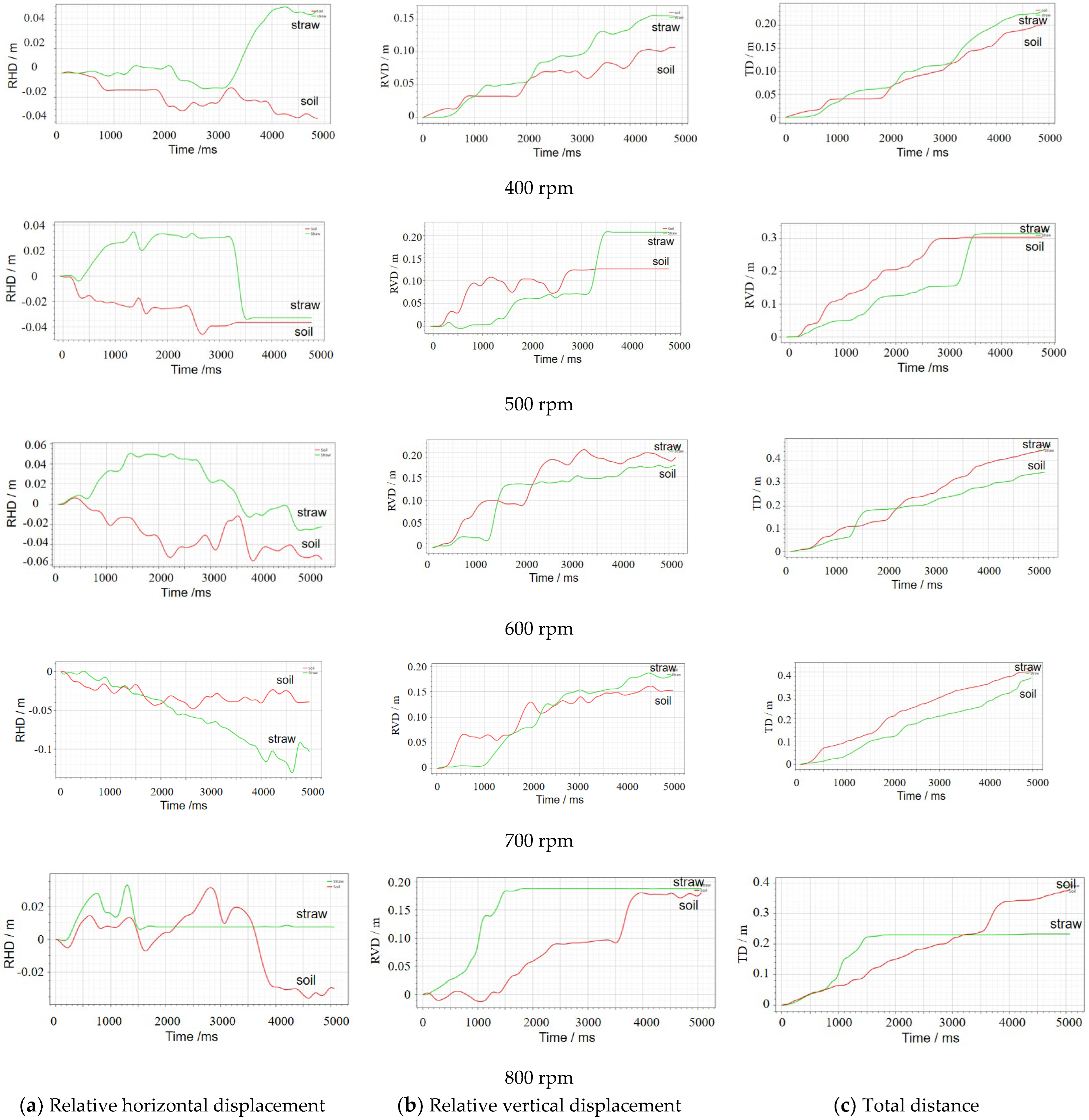
4.1.3. Analysis of Soil and Straw Movement

The movement of straw and soil was recorded by high-speed camera when the rotary speed of the outward blade was 400–800 rpm. The trajectory of straw and soil was extracted during tillage blade rotating (Figure 7) by Kinovea software. According to the linear motion function, the relationship between the horizontal displacement (RHD), vertical displacement (RVD), total distance (TD), and time of straw and soil at each rotary speed was obtained (Figure 8). From the graph analysis, it can be seen that the straw-throwing separation and the soil-cutting separation can be completed in a blade rotation cycle when the blade contacts the straw and the soil at a certain speed. With the increase of the speed, the total displacement increases. The relative horizontal displacement and the relative vertical displacement are respectively expressed as the lateral and the forward displacement of the tillage blade acting on the straw and soil. From the lateral and forward direction, the lateral displacement and the forward displacement increased with the increase of the rotary speed, and the forward displacement was greater than the lateral displacement. The total displacement of soil was greater than that of straw in the same timeframe. With the increase of rotary speed, the time required to form the same vertical displacement was shorter. The relative horizontal displacement changed within a certain range in the same timeframe, and the movement was relatively stable. The change trend of the relative horizontal displacement was the same at 500 rpm and 600 rpm. The change range of the displacement was the smallest at 400 rpm and 800 rpm, and the change range of the relative horizontal displacement was the largest at 700 rpm. This was mainly different from the lateral force of the tillage blade on the straw and soil at different times, resulting in irregular changes in the horizontal displacement. During the test, the small soil particles led to the large tracking range which resulted in only the overall analysis of soil movement trend being conducted.
The results of the stubble cleaning were analyzed through the soil bin test. When the blade was installed outward, the straw and soil were distributed on both sides of the furrow type, and an 8–10 cm width bulge was formed in the middle (Figure 9a). When the blade was installed inward, the straw and soil were piled up behind the device to form a furrow with a width of 21–25 cm, and the convex layer in the middle of the furrow was small (Figure 9b). No-tillage (less-tillage) sowing requires the minimum residue coverage on the seed belt as long as it does not affect the trafficability of the opener. From the test results it can be concluded that the stubble-cleaning rate is more in line with the requirements when the blade is inward.

4.2. Analysis of Anti-Blocking Performance of Oblique Placement

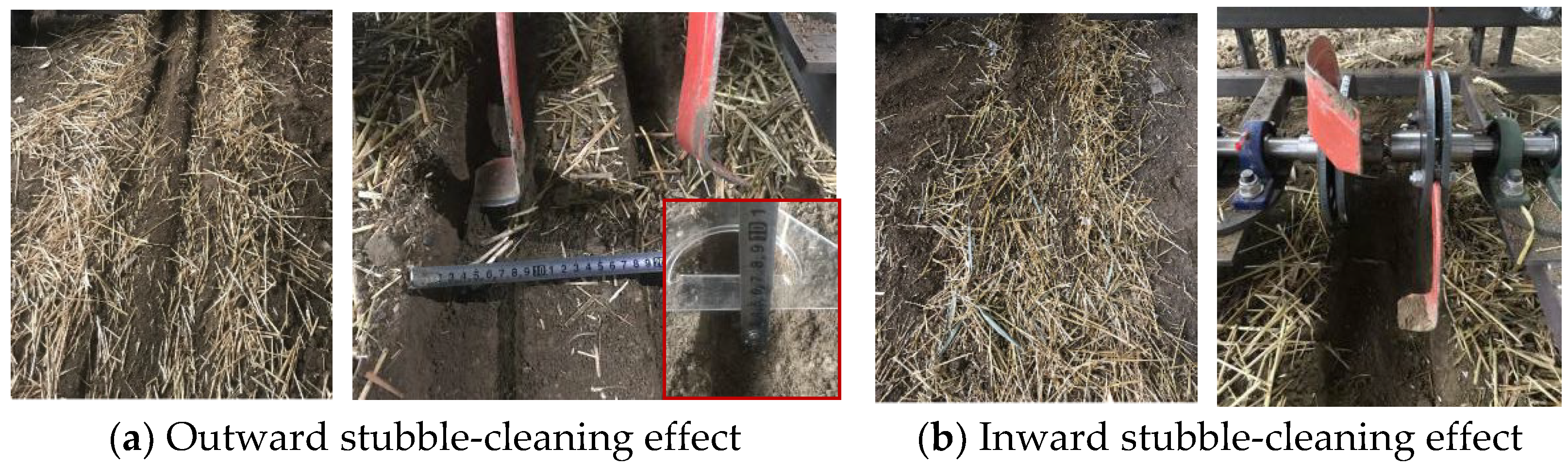
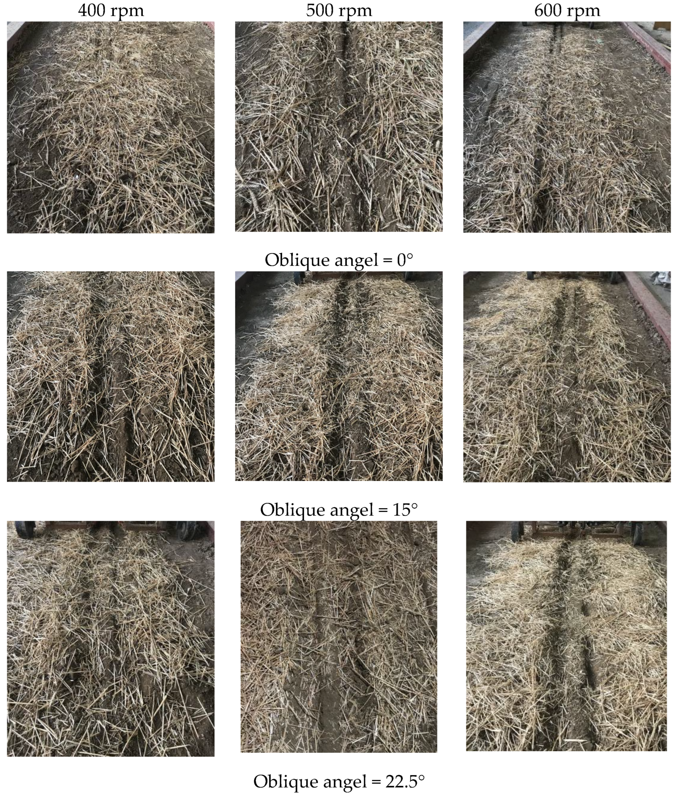
4.2.1. Analysis of Stubble-Clearing Effect

Through the analysis of the experimental data, the change curve of the rotary speed and the stubble-cleaning rate (Figure 10a) were obtained. It can be seen that the stubble cleaning rate was positively correlated with the rotary speed when the oblique angle was constant. With the increase of the rotary speed, the stubble-cleaning rate increases. When the oblique angle was 30°, the stubble-cleaning rate could reach more than 97%. When the rotary speed was constant, the stubble-cleaning rate increased with the increase of the oblique angle. When compared with the oblique angle of 0°, it was obvious that the straw side throwing amount increased with the increase of the oblique angle (Figure 11). Increasing the oblique angle and rotary speed could effectively reduce the straw residue on the seedbed and achieve the seedling belt cleaning.

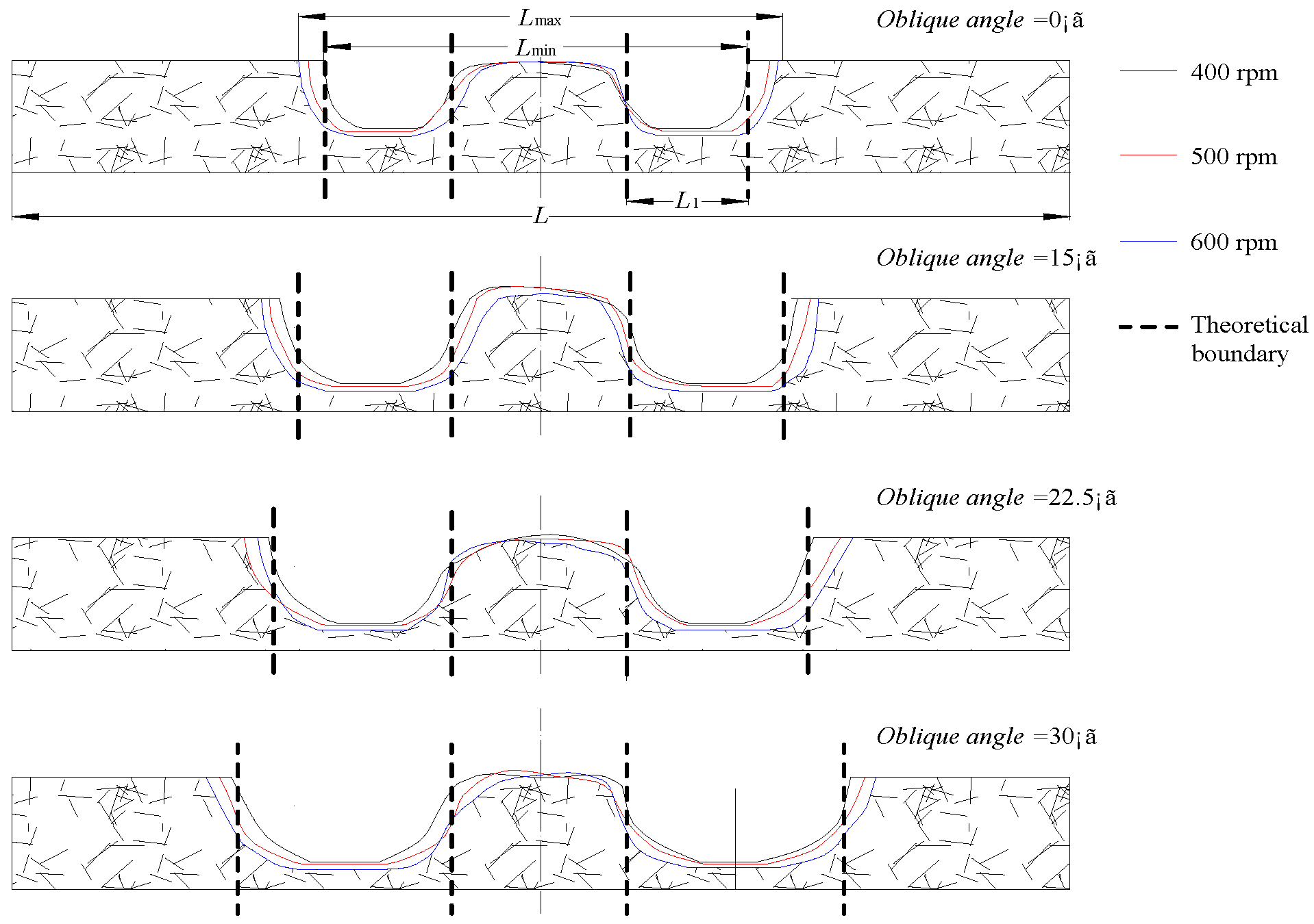
4.2.2. Seedbed Parameters

During the test, a single blade formed a U-shaped furrow in the soil bin. With the increase of the rotary speed, the soil cutting pitch decreased, the soil-breaking rate increase, and the bulge height in the furrow bottom decreased. When the anti-blocking device works in the soil bin covered with straw, it formed a W-shaped furrow on the seedling belt. Because of the interaction between the tillage blade with straw and soil, the shape of the bottom and both sides of the furrow was irregular. The section shape of the groove is shown in Figure 12. Where, L is the working width, Lmin is the minimum moving soil width of the tillage blade, Lmax is the maximum dynamic soil width of the tillage blade, and L1 is the theoretical dynamic soil width of the single side of the tillage blade. It can be seen that the cross-sectional area of the furrow and the boundary of the furrow increased with the increasing of rotary speed. Furthermore, the convex boundary formed in the middle was more unstable, and the depth of the bottom from the plane was more uniform. At the same time, the amount of broken straw and soil in the furrow decreased with the increasing of rotary speed. In summary, the rotary speed should be selected on the basis of the operation requirements. The smaller rotary speed obtains the better seedbed parameters.
According to the test data, it can be seen that the rotary speed and oblique angle of blade shaft were positively correlated with the soil-disturbance coefficient and dynamic soil rate (Figure 10b,c) and negatively correlated with soil-backfill rate (Figure 10d). Under the same rotary speed, with the increase of the oblique angle, the soil-disturbance coefficient increased by 15 percentage points, the dynamic soil rate increased by 25 percentage points, and the soil-backfill rate decreased by 20 percentage points. Under the same oblique angle, with the increase of the rotary speed, the soil-backfill rate decreased, and the soil-disturbance coefficient and dynamic soil rate increased with stable changing. It can be clearly seen from Figure 9 that the rotary speed and oblique angle had a greater influence on the parameters of the seedbed, in which the influence of oblique angle on soil-disturbance coefficient and dynamic soil rate was greater than that of the rotary speed, and the influence of the rotary speed on the soil-backfill rate was greater than that of the oblique angle. Therefore, the quality parameters of the seedbed can be effectively improved by reducing the oblique angle and rotary speed.

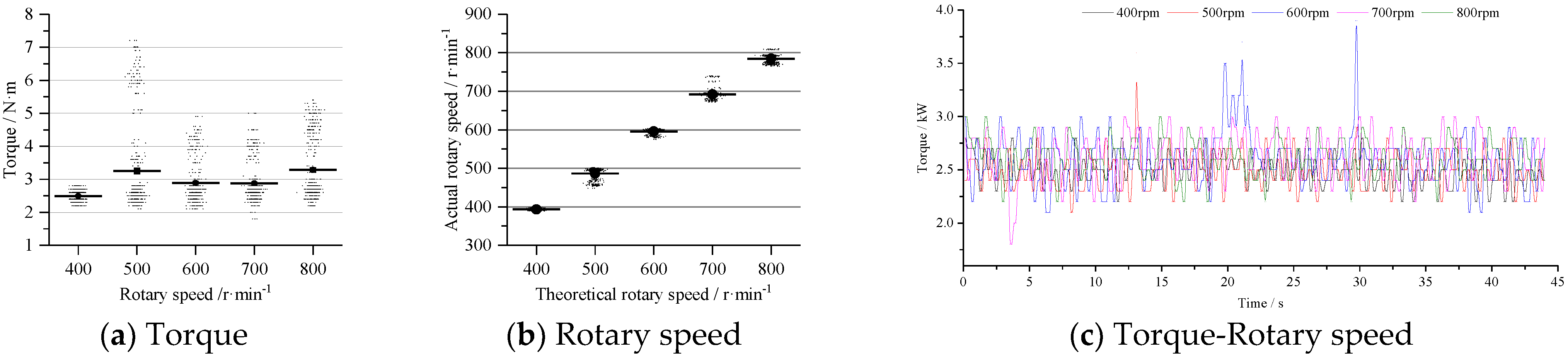
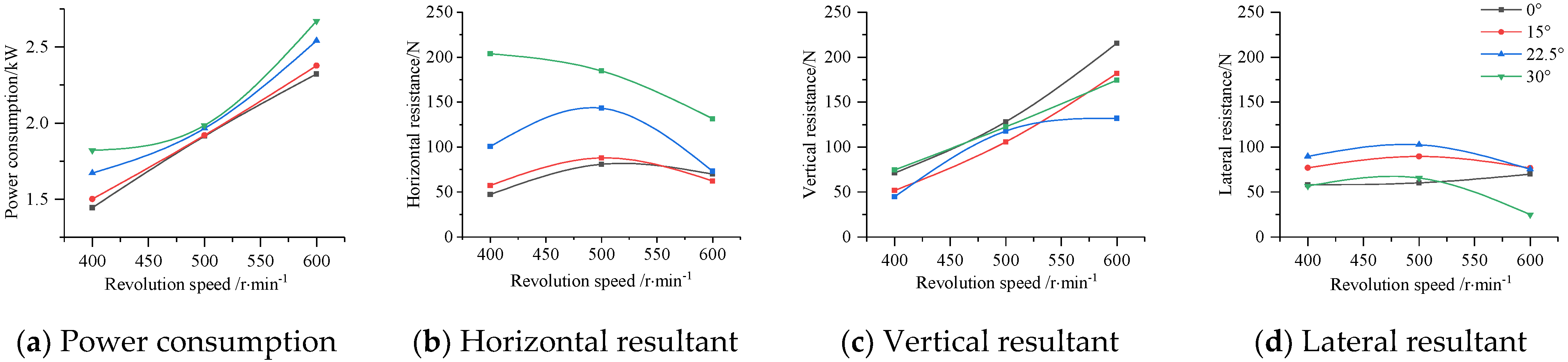
4.2.3. Power Consumption

The particularity of the device could not accurately obtain the instantaneous power consumption and resistance value of the contact between the tillage blade and different positions on the ground. According to the torque measured by the torque sensor, the relationship between the power consumption and rotary speed is shown in Figure 13a. The power consumption is affected with the increase of the oblique angle at the same rotary speed. When the speed was 500 rpm, the overall power consumption had little difference. The power consumption increased with the increasing of the rotary speed. Therefore, the rotary speed could be appropriately reduced in the premise of meeting the anti-blocking requirements.
The horizontal resultant force (Figure 13e), vertical resultant force (Figure 13f), and lateral resultant force (Figure 13g) of the force-measuring frame were obtained from the six-component force sensor. The horizontal resultant force reflects the resistance in the forward direction of the machine. The vertical resultant force reflects the resultant force in the gravity direction of the machine, which has an important impact on the working stability. The lateral resultant force reflects that the resultant force on the left and right sides affects the stability of the machine when the machine is working. Combined with the results of the torque sensor and the six-component force sensor, the trend of the three-dimensional resultant force under different rotary speeds and oblique angles was obtained. The horizontal resultant force had the same movement trend and the overall difference was not large under the rotary speed conditions of different oblique angles. The vertical force and the lateral force with other oblique angles were significantly higher than that with 0°, and the direction of the resultant force was opposite. In order to clarify the force condition of the device during operation, the difference between the force-measuring frame under a stable working condition and static rotation condition was analyzed (ignoring the error of the sensing transmission process). The relationship between the three-dimensional working resistance of the tillage blade at different rotary speeds and oblique angle was obtained (Figure 13b–d). It can be seen that the difference between the vertical resistance and lateral resistance was relatively small, while the horizontal resistance varied greatly when the rotational speed was 400–500 rpm under a certain oblique angle. In the case of a certain rotary speed, the horizontal resistance increased with the increase of the oblique angle; the vertical resistance and lateral resistance changes were more complex.

5. Discussion

  • Due to the difference of straw moisture content and soil texture in corn planting areas, the working environment of the corn seeder in the field was more complex. The influence of the lack of root remains on the stubble-cleaning device in the soil bin test only verified the stubble-cleaning performance test of the harvested surface straw and the stubble-cleaning performance test under the condition that the soil environment was relatively close to the field. The sensor value of the force-measuring frame had errors in the measurement process, which lead to the uneven change of the three-dimensional resistance. However, the resistance of the stubble-cleaning device could still be obtained when it was working.
  • This research was a verification test of the stubble-cleaning performance of a type of tillage blade structure. By changing the position and structure of different tillage blades, the change of the oblique of the tillage blade could be achieved, and the stubble area (cutting width) and stubble angle could be increased with the oblique angle to achieve wide stubble cleaning. At present, the change of the structure of the blade and the anti-blocking of wheat stubble are rarely reported. On the basis of this research, the appropriate blade structure can be sought by changing different blade types to achieve the purpose of reducing power consumption and soil disturbance.

6. Conclusions

(1)
In this paper, a shallow strip tillage and stubble-cleaning method was proposed to solve the problems existing in the no-tillage sowing of corn, which can be applied to the situation with a large amount of straw mulching. It was determined that the upright external mounting was more suitable for the stubble-cleaning device when the rotary speed was 400–600 rpm. On the basis of keeping the structural parameters of the rotary tillage blade, the oblique shallow rotary tillage was realized by changing the inclination of the positive outward installation. Taking the straw-clearance rate, seedbed parameters, and power consumption as indicators, the relationship between each factor level and each indicator was determined.
(2)
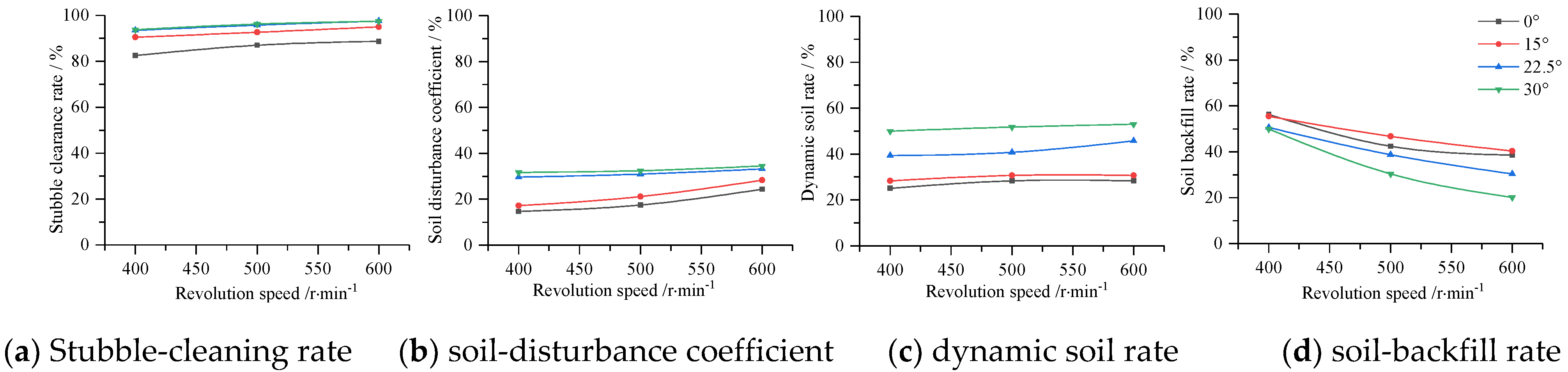
A torque sensor and six-component force sensor were applied to the soil bin test platform to study the effects of four oblique angles (0°, 15°, 22.5°, 30°) on the stubble-cleaning effect, seedbed parameters, and power consumption at three rotary speeds (400, 500, 600 rpm). The results show that increasing the oblique angle and rotary speed could effectively reduce the straw residue on the seedbed and realize the cleaning of the seedling belt. The rotary speed and oblique angle had a great influence on the parameters of the seedbed. The influence of the oblique angle on the soil-disturbance coefficient and dynamic soil rate was greater than that of rotary speed. The influence of the rotary speed on the soil-backfill rate was greater than that of the oblique angle. Reducing the oblique angle and rotary speed could effectively improve the quality parameters of the seedbed. When the rotary speed was 400–500 rpm, the difference between the vertical resistance and lateral resistance was relatively small under different oblique angles, while the horizontal resistance was large. In the case of a fixed rotary speed, the horizontal resistance increased with the increase of the oblique angle; the vertical resistance and lateral resistance changes were more complex.
(3)
This test was also a verification test of a shallow rotary stubble-cleaning device to determine the influence of each factor on the stubble-cleaning rate, seedbed parameters, power consumption, and three-dimensional resistance. The parameter range of each factor can be selected according to the demand index. In the later stage, the rotary speed, oblique angle, and device structure can be selected and optimized by allocating the weight of each index. In the future, it is possible to achieve a low soil-breaking rate and soil-disturbance coefficient of the seedbed, low power consumption, and high stubble cleaning by replacing different blade types, so as to meet the requirements of no tillage sowing with different stubble coverage and different straw types.

Author Contributions

Conceptualization, W.Y. and P.D.; methodology, W.Y.; software, W.Y.; validation, W.Y. and S.L.; formal analysis, W.Y.; investigation, W.Y., H.M. and S.L.; resources, W.Y.; data curation, W.Y., H.M. and S.L.; writing—original draft preparation, W.Y.; writing—review and editing, W.Y., P.D., H.M. and S.L.; project administration, P.D.; funding acquisition, P.D. All authors have read and agreed to the published version of the manuscript.

Funding

This work was funded by National Key Research and Development Project of China (Grant No.2021YFD2000401-2), Shandong Major Science and Technology Innovation Project of China (Grant No.2019JZZY020615).

Institutional Review Board Statement

Not applicable.

Data Availability Statement

Not applicable.

Conflicts of Interest

The authors declare no conflict of interest.

References

  1. Nie, S.W. Effects of Straw Incorporation in Wheat-Maize Cropping System by Farm Mechanization. Master’s thesis, Henan Agricultural University, Zhengzhou, China, 2007. [Google Scholar]
  2. Gao, N.N. Study on Anti-Blocking Technology of Pushing and Separating Approaches for Maize No-Till Planting in Two-Crops-a-Year Areas. Ph.D. Thesis, China Agricultural University, Beijing, China, 2014. [Google Scholar]
  3. Dong, Z.P.; Zhang, X.L.; Zhang, Y.G. Damage characteristics occurrence regularity and control technology of proxenus lepigone. J. Hebei Agric. Sci. 2011, 15, 1–4. [Google Scholar]
  4. Torbert, H.A.; Ingram, J.T.; Prior, S.A. Planter aid for heavy residue conservation tillage systems. Agron. J. 2007, 99, 478–480. [Google Scholar] [CrossRef] [Green Version]
  5. Negadi, J.; Raoufat, M.H. Field performance of a pneumatic row crop planter equipped with active toothed coulter for direct planting of corn in wheat residue. Span. J. Agric. Res. 2013, 11, 327. [Google Scholar] [CrossRef] [Green Version]
  6. Fan, X.H.; Jia, H.L.; Zhang, W.H. Parametric analysis of finger-type anti-blocking residue-cleaner for no-till planting. Trans. CSAM 2011, 42, 56–60. [Google Scholar]
  7. Jia, H.L.; Liu, H.; Yu, H.B. Simulation and experiment on stubble clearance mechanism with concave claw-type for no tillage planter. Trans. CSAM 2018, 49, 68–77. [Google Scholar]
  8. Zhao, H.B.; He, J.; Li, H.W. Design and experiment of strip rotary-cut-throw anti-blocking implement. Trans. CSAM 2018, 49, 65–75. [Google Scholar]
  9. He, J.; Li, H.W.; Chen, H.T.; Lu, C.Y.; Wang, Q.J. Research progress of conservation tillage technology and machine. Trans. CSAM 2018, 49, 1–19. [Google Scholar]
  10. Zhao, J.L.; Jia, H.L.; Guo, M.Z.; Jiang, X.M.; Qu, W.J.; Wang, G. Design and experiment of supported roll-cutting anti-blocking mechanism with for no-till planter. Trans. CSAE 2014, 30, 18–28. [Google Scholar]
  11. Wang, H.Y.; Chen, H.T.; Ji, W.Y. Design and experiment of cleaning and covering mechanism for no-till seeder in wheat stubble fields. Trans. CSAE 2012, 28, 7–12. [Google Scholar]
  12. Gu, F.W.; Hu, Z.C.; Chen, Y.Q.; Wu, F. Development and experiment of peanut no-till planter under full wheat straw mulching based on “clean area planting”. Trans. CSAE 2016, 32, 15–23. [Google Scholar]
  13. Jiang, J.L.; Gong, L.N.; Wang, D.W.; Wang, G.P. Design and experiment for driving double coulters anti-blockage device of no-till planter. Trans. CSAE 2012, 28, 17–22. [Google Scholar]
  14. Kong, L.D.; Sang, Z.Z.; Wang, G.L. Experimental study on oblique rotary tillage. Trans. CSAM 2000, 31, 30–34. [Google Scholar]
  15. Gao, J.M.; Liu, X.D.; Qi, H.D. Simulation and experiment of soil casting during oblique submerged reversely rotary tillage. Trans. CSAE 2019, 35, 54–63. [Google Scholar]
  16. Chen, H.T.; Hou, L.; Hou, S.Y. Design and optimization experiment of anti-blocking mechanism of no-tillage planter for grand ridge with raw corn stubble. Trans. CSAM 2018, 49, 59–67. [Google Scholar]
  17. Fang, H.M.; Ji, C.Y.; Zhang, Q.Y.; Guo, J. Force analysis of rotary blade based on distinct element method. Trans. CSAE 2016, 32, 54–59. [Google Scholar]
  18. Fang, H.M.; Ji, C.Y.; Ahmed, A.T.; Zhang, Q.Y.; Guo, J. Simulation analysis of straw movement in straw-soil-rotary blade system. Trans. CSAM 2016, 47, 60–67. [Google Scholar]
  19. Fang, H.M.; Ji, C.Y.; Farman, A.C.; Guo, J.; Zhang, Q.Y.; Chaudhry, A. Analysis of soil dynamic behavior during rotary tillage based on distinct element method. Trans. CSAM 2016, 47, 22–28. [Google Scholar]
  20. Australian Centre for International Agricultural Research. Available online: https://www.aciar.gov.au/publication/development-conservation-farming-implements-two-wheel-tractors-power-tillers-cambodia (accessed on 1 September 2022).
  21. Matin, M.A.; Desbiolles, J.M.A.; Fielke, J.M. Strip-tillage using rotating straight blades: Effect of cutting edge geometry on furrow parameters. Soil Tillage Res. 2016, 155, 271–279. [Google Scholar] [CrossRef]
  22. Matin, M.A.; Fielke, J.M.; Desbiolles, J.M.A. Furrow parameters in rotary strip-tillage: Effect of blade geometry and rotary speed. J. Biosyst. Eng. 2014, 118, 7–15. [Google Scholar] [CrossRef]
  23. Yao, W.Y.; Zhao, D.B.; Miao, H.Q.; Cui, P.D.; Wei, M.J.; Diao, P.S. Design and experiment of oblique anti-blocking device for no-tillage planter with shallow plowing stubble clearing. Trans. CSAM 2022, 53, 42–52. [Google Scholar]
  24. GB/T20865-2017. S.; Agricultural Industry Standards of the People’s Republic of China. No or Little-Tillage Fertilizes-Seeder. China National Standardization Administration, General Administration of Quality Supervision, Inspection and Quarantine of the People’s Republic of China: Beijing, China, 2017.
Figure 1. Test equipment.
Agriculture 12 01728 g001
Figure 2. Structure diagram of upright shallow rotary stubble clearing.
Agriculture 12 01728 g002
Figure 3. Structure diagram of oblique shallow rotary stubble cleaning.
Agriculture 12 01728 g003
Figure 4. Relationship between the rotary speed and torque of the inward blade.
Agriculture 12 01728 g004
Figure 5. Relationship between the rotary speed and torque of the outward blade.
Agriculture 12 01728 g005
Figure 6. Power consumption and torque variation curve.
Agriculture 12 01728 g006
Figure 7. Trajectory of straw and soil.
Agriculture 12 01728 g007
Figure 8. Straw and soil linear motion.
Agriculture 12 01728 g008
Figure 9. Straw dispersion.
Agriculture 12 01728 g009
Figure 10. Test index.
Agriculture 12 01728 g010
Figure 11. Test effect.
Agriculture 12 01728 g011
Figure 12. Furrow boundary line.
Agriculture 12 01728 g012
Figure 13. Power consumption and three-dimensional force variation curve.
Agriculture 12 01728 g013aAgriculture 12 01728 g013b
Publisher’s Note: MDPI stays neutral with regard to jurisdictional claims in published maps and institutional affiliations.

