Review

Advances in Methanol Production and Utilization, with Particular Emphasis toward Hydrogen Generation via Membrane Reactor Technology

1
Chemistry & Chemical Technologies Department, University of Calabria, Cubo 15/D, Via P. Bucci, 87036 Rende, CS, Italy
2
Department of Ambient, Territory and Chemical Engineering, University of Calabria, Cubo 44/A, Via P. Bucci, 87036 Rende, CS, Italy
3
Laboratoire de Chimie des Matériaux et Catalyse, Département de Chimie, Faculté des Sciences de Tunis, Université Tunis El Manar, Tunis 2092, Tunisia
4
Institute on Membrane Technology of the Italian National Research Council (CNR-ITM), Via P. Bucci, c/o University of Calabria, Cubo 17/C, 87036 Rende, CS, Italy
*
Author to whom correspondence should be addressed.
Membranes 2018, 8(4), 98; https://doi.org/10.3390/membranes8040098
Submission received: 11 September 2018 / Revised: 12 October 2018 / Accepted: 14 October 2018 / Published: 18 October 2018

Abstract

:
Methanol is currently considered one of the most useful chemical products and is a promising building block for obtaining more complex chemical compounds, such as acetic acid, methyl tertiary butyl ether, dimethyl ether, methylamine, etc. Methanol is the simplest alcohol, appearing as a colorless liquid and with a distinctive smell, and can be produced by converting CO2 and H2, with the further benefit of significantly reducing CO2 emissions in the atmosphere. Indeed, methanol synthesis currently represents the second largest source of hydrogen consumption after ammonia production. Furthermore, a wide range of literature is focused on methanol utilization as a convenient energy carrier for hydrogen production via steam and autothermal reforming, partial oxidation, methanol decomposition, or methanol–water electrolysis reactions. Last but not least, methanol supply for direct methanol fuel cells is a well-established technology for power production. The aim of this work is to propose an overview on the commonly used feedstocks (natural gas, CO2, or char/biomass) and methanol production processes (from BASF—Badische Anilin und Soda Fabrik, to ICI—Imperial Chemical Industries process), as well as on membrane reactor technology utilization for generating high grade hydrogen from the catalytic conversion of methanol, reviewing the most updated state of the art in this field.

Graphical Abstract

1. Introduction

In the last century, fossil fuels represented the main source of energy production. These feedstocks are not renewable, are limited and, consequently, are responsible for an instable global market, which leads to a corresponding instability in fuel price. Moreover, fossil fuel exploitation is considered primarily responsible for greenhouse gas (GHG) emissions, contributing to the increase in global warming.
Today, the most viable options for the exploitation of fossil fuels for power production result from hydrogen and methanol. The use of hydrogen appears very promising, as it shows the highest energy content per unit of weight (142 kJ/g) over any other known fuel and, furthermore, it is environmentally safe [1]. However, the key issues for wide hydrogen utilization as a new energy carrier are represented by its purification costs and by the difficulties linked to the infrastructure for its storage and transportation.
By contrast, methanol is easily stored and transported and can be used as a convenient hydrogen carrier. It is also particularly useful in the chemical industry as a solvent and as a C1 building block for producing intermediates and synthetic hydrocarbons, including polymers and single-cell proteins [2,3]. In vehicle transportation, methanol can be mixed with conventional petrol, without requiring any technical modification to the vehicle fleet. In fact, most methanol-fueled vehicles currently use M85 fuel, which represents a mixture containing 85% methanol and 15% unleaded gasoline [4].
Approximately 65% of methanol worldwide is consumed for the production of acetic acid, methyl and vinyl acetates, methyl methacrylate (MMA), methylamines, metil-t-butil etere (MTBE), fuel additives, and other chemicals. The remaining portion is converted into formaldehyde and other products [3,5,6], as illustrated in Figure 1.
A number of technologies were developed over the years to produce methanol, including several feedstocks, such as natural gas, coal, and biomass or CO2—the latter directly recoverable from the atmosphere [3,7].
From an historic point of view, methanol production processes took place before the 1660s (by Robert Boyle). An important contribution to its development was by Paul Sabatier, who carried out the hydrogenation of a large variety of functional groups by metal-based catalysis [8]. Methanol synthesis was performed by BASF (Germany) in 1923, developing a metal-based catalytic hydrogenation process at high pressure [9]. The BASF process has then been utilized since 1927 by both DuPont and the Commercial Solvents Corporation in the USA, representing the start point in the methanol production industry and remaining the dominant technology for over 45 years [10].
Successively, in the 1940s, the Swiss Lonza Company produced methanol industrially from electrolytic hydrogen and CO2, the latter derived from Ca(NO3)2 synthesis. The reactant gas purification from nitrous vapors was then developed by Natta (Italy) and combined with the methanol synthesis from CO and H2 [11].
The successive development of the steam methane reforming (SMR) reaction, able to generate syngas (a mixture of H2, CO, and CO2) combined with active Cu/ZnO catalysts, made it possible to operate at milder conditions, such as 300 °C and 100 bar. This was the core of the “ICI process”, proposed in 1966 [3].
In 1973, during the oil embargo proclaimed by the Organization of Arab Petroleum Exporting Countries in the USA and The Netherlands, the interest toward methanol exploitation as an alternative automobile fuel was particularly intense, even though it was definitively banned after the 1990s due to the harmful methanol combustion products negatively affecting the ozone layer. In the same period, methanol market demand grew once again as a consequence of its large utilization as a fertilizer in agriculture.
Methanol is currently produced all around the world (over 90 methanol plants facilitate a production capacity of around 110 million tons [3], Figure 2): North and South America, Europe, Asia, and there are also some plants in Africa. Moreover, global methanol consumption is valued at an average of around 100 Mt/year, growing very fast in the last four decades [7,12].
In the last three decades, the potential of methanol utilization as a hydrogen carrier was also demonstrated [13]. Furthermore, an extensive range of literature was addressed at hydrogen production through steam reforming reaction [14,15,16,17,18,19,20]. Compared to steam methane reforming (SMR) reaction (usually carried out between 800 °C and 1000 °C), methanol steam reforming (MSR) attracted particular interest because it takes place at significantly lower temperatures, around 240–260 °C. The MSR process can be described by three partial chemical reactions:
CH3OH + H2O = CO2 + 3H2   ∆H°298K = +49.7 (kJ/mol),
CO + H2O = CO2 + H2   ∆H°298K = −41.2 (kJ/mol),
CH3OH = CO + 2H2   ∆H°298K = +90.7 (kJ/mol).
The MSR reaction is represented by Equation (1), and Equation (2) is the water gas shift (WGS) reaction, while Equation (3) is the methanol decomposition reaction. Apart from in Equations (1) and (3), which are endothermic and involve a volume increase, the WGS reaction is exothermic and occurs without volume change.
In the following, the state of the art about methanol production, its representative production processes, the most interesting advancements on its utilization for generating hydrogen, combined to the application of methanol in fuel cells is reported.

2. Methanol Production

Methanol is producible from a number of carbon-based feedstocks, such as natural gas, coal, biomass, and CO2. Successively, some of the most important methanol production processes are hence examined in detail and related reactions and technologies discussed in depth.

2.1. Natural Gas as a Primary Source of Methanol Production

Today, around 90% of methanol comes from natural gas [21]. The steps for producing methanol are relatively straightforward and can be summarized to the followings three basic stages: (1) Synthesis gas production; (2) syngas conversion into crude methanol; (3) crude methanol distillation to reach the required purity [22,23,24].
Both steam and autothermal reforming (SMR and AMR, respectively) of natural gas (Equations (4) and (5)) are needed to generate the syngas mixture (mainly composed by H2, CO, and CO2), even though it can also be obtained via partial oxidation of methane (POM) (Equation (6)) or different carbon-based materials, such as coal, heavy oils, or biogases [25].
CH4 + H2O = CO + 3H2
CH4 + 2O2 → CO2 + 2H2O
CH4 + ½O2 → CO + 2H2
The composition of syngas normally depends on the S ratio (Equation (7)), represented by the hydrogen and carbon dioxide moles difference over the CO2 and CO moles sum.
S =   moles   H 2 moles   CO 2 moles   CO 2 + moles   CO
In ideal conditions, methanol production should require S = 2. The S number considers the continuous CO2 conversion with hydrogen into methanol via reverse WGS reaction. However, third parameter strictly depends on the adopted feedstock and this is the reason why, for example, if syngas is obtained from natural gas reforming, the S value ranges from 2.8 to 3. The second step to convert syngas into crude methanol is performed in the ranges 50–100 bar and 200–300 °C and the process mechanism is resumed below:
CO + 2H2 = CH3OH.
Reaction (8) is subdivided in two consecutive steps:
CO + H2 = CH2O,
CH2O + H2 = CH3OH.
In addition to Reaction (8), methanol is also produced by Reaction (11):
CO2 + 3H2 = CH3OH + H2O.
For the traditional gas phase process, the H2/CO ratio changes from 3:1 to 5:1 and the process requires a WGS stage to boost the hydrogen content. By contrast, for the liquid phase process, its superior heat management capabilities may handle the synthesis gas straight from the generator, with a ratio between 1:1 and 1:2, as generated by coal gasifiers [9]. Another issue to be considered is the thermodynamic equilibrium regulating the conversion of synthesis gas, which limits the process to low conversion and, consequently, imposes the recycling of a high amount of unconverted gas. Recycling and cooling duty are the main investment costs of this step process, although the continuous research in this field has allowed several solid catalysts to be developed, able to maximize methanol yield and selectivity, while lowering the formation of byproducts.

2.1.1. Methanol Production through BASF Process

In the second decade of the 20th century, the hydrogenation of carbon monoxide giving methanol over iron-based catalysts at 500 °C and high pressure (100 bar) was pursued by Mittash et al. [26]. Successively, they performed methanol production using waste gases derived from ammonia synthesis, observing that this reaction produces various products in addition to methanol (Table 1), unfortunately thermodynamically more favored with respect to the latter [11,22]. Another key issue was the low methanol yield caused by pollutants present in the reactant gases, which were responsible for the deactivation of the Fe-based catalyst, the reaction between CO and Fe themselves, and the consequent penta-coordinate complexes formation [11].
Therefore, a part from the eighth group of the periodic system, many oxide- and metal-based catalysts were used for the hydrogenation reaction, carrying out this process at 250–300 bar and temperatures between 320 and 450 °C. At these operating conditions, the experimental results given by ZnO/Cr2O3 and ZnO/CuO catalysts were particularly interesting [9,22,26,27,28,29]. Based on the aforementioned solid catalysts, two ways were proposed for describing the reaction mechanism, both involving CO and H2 adsorption [30,31,32,33]. Figure 3 illustrates a scheme of the reaction mechanism taking place in four consecutive hydrogenation steps.
Figure 4 illustrates that, in the second proposed mechanism, both CO and a hydroxyl group are present on the catalyst surface, with the CO generating a formate intermediate; successively, hydrogenation and dehydration reactions are responsible for methanol production through a methoxide intermediate. These two mechanisms are completely different, firstly because they do not form the same intermediates and, secondly, because the latter is differently bonded to the catalyst surface. In the mechanism of Figure 3, they are bonded with C atoms, whereas in that of Figure 4 to O atoms.
In recent years, ZnO/Cu-based catalysts were the main subject of several scientific studies [27,28,34,35,36,37,38]. The mixture between Cu and ZnO creates small aggregates, in which ZnO is aggregated around Cu, forming a core–shell structure responsible for the selectivity of methanol production. This aggregate is formed partially by Cu, part of the shell comprises a Cu/Zn alloy, and the outermost part of the shell is represented by ZnOx (selective to the formation of methanol), where the vacations of oxygen are located, while another part of the aggregate consists of ZnO (Figure 5).
Tisseraud et al. [37] hypothesized that the morphostructural arrangement of the molecular aggregate plays a significant role in the catalyst’s selectivity towards methanol. In this structure, both H2 and CO2 are selectively chemisorbed on different surfaces of the catalyst. In fact, Cu does not adsorb CO2, but adsorbs hydrogen, albeit weakly, while CO2 is adsorbed on the surface of ZnO and ZnOx. As already reported in literature [27], H2 is weakly chemisorbed on metallic Cu due to its well-known characteristic to rapidly dissociate and recombine hydrogen. The weakly adsorbed H2 is then poured both on the ZnOx (leading to the formation of methanol) and ZnO part (leading to the formation of CO). A schematic representation of the Cu/ZnO catalytic mechanism is hence shown in Figure 6.
Tisseraud et al. [37] also reported a Cu-ZnOx/ZnO catalyst design; the ZnOx active phase should completely cover the Cu-sized particles, thus avoiding CO formation (unwanted product), making the catalyst highly selective toward methanol formation.

2.1.2. Methanol Production through ICI PROCESS

The hard experimental conditions imposed by the BASF process induced strong efforts to realize methanol synthesis at lower pressures. This was achieved by ICI Company (today, Johnson Matthey), which proposed a new methanol synthesis process in the pressure range from 35 to 54 bar and at temperatures from 200 to 300 °C. This goal was also due to the development of new Cu-based catalysts (Cu/ZnO/Al2O3) [28,29,30], but also to the development of new advanced separation/purification processes of synthesis gas, with the advantage of using sulfur–chlorine-free syngas [31,32,33]. However, although Cu/Zn-based catalysts proved to be very efficient in the methanol synthesis process, their wide utilization was negatively affected by their limited lifetime and low thermal stability [34]. These issues were overcome by adding alumina to the catalysts, responsible for the enhancement of catalytic stability, while depleting the Cu crystallites’ thermal formation [34,35,36]. Among several kinds of catalytic systems, Cu/ZnO/Al2O3-based catalysts seem to be the most promising ones. Liao et al. [39] reported significant morphology-dependent Cu–ZnO interactions, while Sun et al. [28] revealed their promotional effects on the catalytic performance of CO2 hydrogenation to methanol. A catalytic cycle is then proposed as a microkinetic model in Figure 7, which shows the scheme of a reaction mechanism where methanol may be generated by CO hydrogenation by means of HCOO, HCOOH, CH2COOH, CH2O, CH3O, or HCO, CH2O, CH3O intermediates [39].
It is worth of noting that, among various methanol production processes, differences in methanol yield (expressed in t/d) exist, depending on the feedstocks used; see Table 2.
As shown in this table, based on syngas as a primary feedstock the methanol yield varies from around 7.9 × 10⁻² t/d with the BASF process to 2.4 × 10³ t/d with the Haldor Topsoe process, while the ICI process makes it possible to reach 2.5·× 103 t/d using carbonaceous feedstocks.

2.2. Biomass and Char as Feedstocks for Methanol Synthesis

The use of biomass and char as feedstocks for methanol synthesis represents a new industrial way to solve the issues of energy demand, waste management, and pollutants emissions [40,41,42]. In the case of coal and biomass exploitation to produce methanol, the synthesis process is also similar to the one based on natural gas. In fact, it also foresees three stages, such as syngas production, crude methanol synthesis, and purification. At first, coal or biomass react in a gasifier to be converted into gaseous products, consisting of biogas (mainly CH4 and CO2), syngas (H2, CO2, and CO), hydrogen, and alkaline gases [43]. The gasification process represents a well-known thermochemical technique, useful for converting solid biomass into gaseous mixtures by means of air/oxygen, steam, and flue gases, and it is normally carried out at 800–1000 °C [33,44].
Otherwise, an alternative process to conventional gasification is represented by the torrefaction or “mild pyrolysis”, which allows the biomass properties’ optimization, making the combustion of biomass possible at temperatures ranging between 200 and 300 °C in anaerobic conditions. Indeed, at this operating temperature, water and other volatile compounds evaporate, leaving the lignocellulosic fraction under degradation with a consequent loss of the initial mass around 20% [31,45]. When methanol is synthesized from syngas via conventional gasification of biomass, the latter may be represented by whatever feedstock containing carbon, such as coal or solid wastes. However, conventional biomass gasification processes do not guarantee a syngas stream which is useful for methanol synthesis, due to the formation of tar and char via reduction of carbon oxides. Consequently, the requirements of synthesis gas which is useful for methanol production foresee a small portion of inert gases.
The catalysts used for producing methanol from syngas require a CO2:CO:H2 ratio = 5:28:63 [46], while the stage of syngas purification from substances which are environmentally harmful [47,48] is normally realized prior to the entrance of gases in the methanol production process.

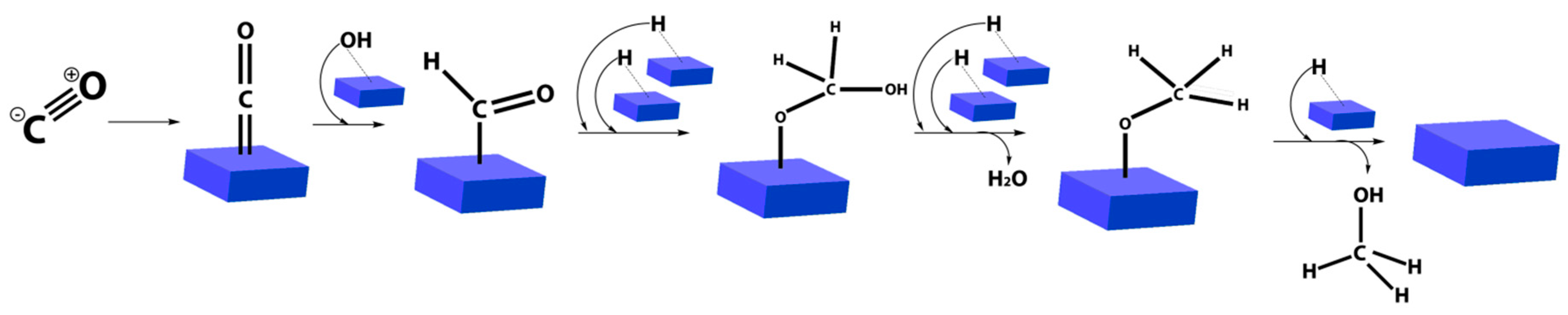
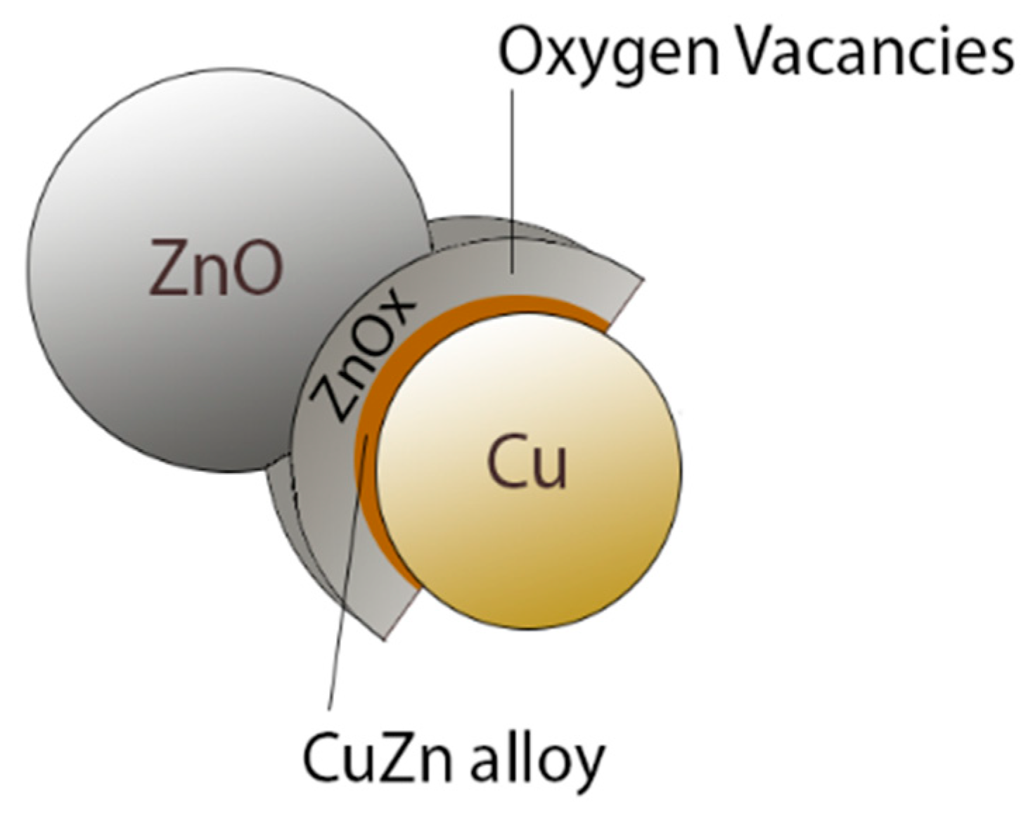
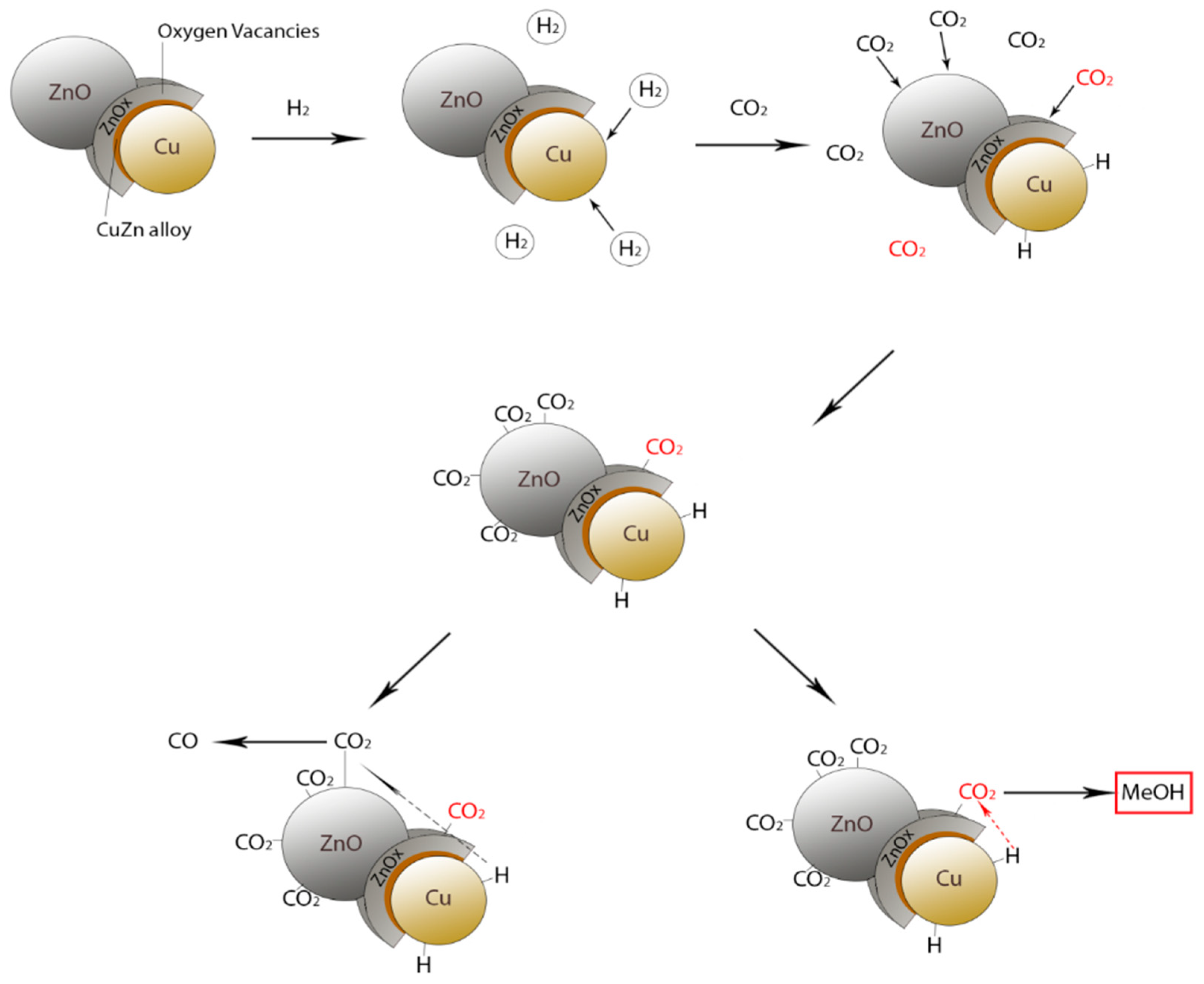
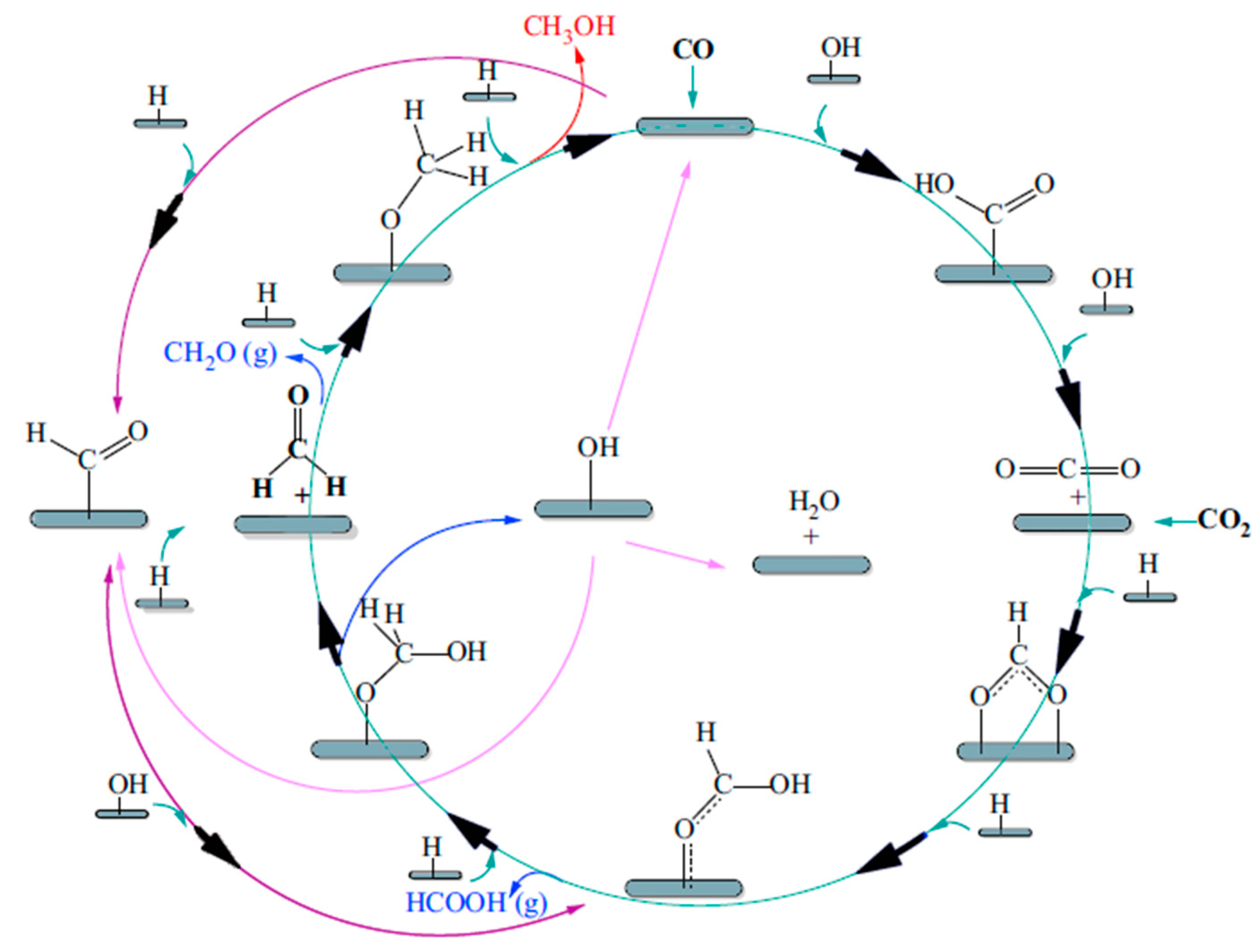
2.3. CO2 Hydrogenation for Methanol Generation

The hydrogenation of CO2 to produce methanol (Equation (11)) may represent a viable green strategy for a sustainable development, oriented to produce added-value chemicals while reducing CO2 emissions in the atmosphere [49]. The utilization of CO2 as a feedstock includes several benefits because it is inexpensive, abundant in nature, nontoxic, noncorrosive, and nonflammable and, therefore, safe to handle. Furthermore, it may be easily stored and its transportation may be realized in liquid form under mild pressure. Methanol production from CO2 is hence advantageous not only for the exploitation of non-fossil fuel sources (unlike syngas), but also because it overcomes CO2 sequestration, which is a very costly process, also mitigating the GHG effect through an efficient recycling of CO2. Hence, CO2 could be separated and stored from human or industrial activities as well as by absorption from air, then converted renewably into methanol. The conversion of CO2 into methanol via hydrogenation reaction (Equation (11)) requires a considerable energy supply; consequently, an adequate catalytic system is needed. Considering the actual importance and interest on the CO2 hydrogenation, a recent progress about its challenges and opportunities may be found in Li et al. [50].
This process is conventionally carried out from 35 to 55 bar and 200 °C, while the highest active and selective catalysts are based on Cu/ZnO/Al2O3. The whole reaction pathway for the methanol production via hydrogenation reaction is reported below:
CO + 2H2 = CH3OH,
CO2 + H2 = CO + H2O,
CO2 + 3H2 = CH3OH + H2O.
From a theoretical point of view, to enhance methanol production in conventional reactors, two main routes (apart from the catalyst improvements) can be also pursued:
(a)
Recycling of the unconverted synthesis gas after products separation by condensation;
(b)
in situ reaction products removal.
However, the catalytic hydrogenation of CO2 using H2 produced with renewable energy is considered a potential path forward for the sustainable production of methanol, but also of lower olefins, higher hydrocarbons, formic acid, and higher alcohols. Furthermore, CO2 hydrogenation represents a promising way to convert it into fuels, among other CO2 hydrogenation paths, needing to evaluate two challenges along with it: (a) Sustainable hydrogen source and (b) dispersed product distribution [51].
Much effort was devoted to solving the former challenge and many scientists have already made great progress in water electrolysis to produce H2 using electricity (Equation (14)) generated with solar or wind or other renewable energy, and water splitting using photocatalytic, photoelectrochemical, or other photochemical processes [52].
2H2O → 2H2 + O2
Nevertheless, at the moment, H2 is produced expensively and not renewably in conventional systems, representing a strong issue for the development of this process at a larger scale [37].

3. Methanol Utilization

In 2010, global methanol demand achieved 49 million tons and, according to the IHS Markit World Analysis—Methanol 2017, by 2021 the demand will overcome 95 million tons, with China playing the role of leader in this market, with around 54% of world capacity and 46% of global production. It is estimated that, by 2021, nearly one in five tons of global methanol production will be useful for the methanol-to-olefins process and to satisfy the Chinese chemical demand. In 2000, China represented 12% of global methanol demand, while North America and Western Europe 33% and 22%, respectively. In the previsions of IHS Markit, Northeast Asia (dominated by China) will account for around 70% of global methanol demand, followed by North America with 9% and Western Europe with 8% [53].

3.1. Methanol Transformation into Dimethylether

Among other chemicals, methanol utilization for di–methyl–ether (DME) production has received growing interest in the last decade. Indeed, methanol plays an important role as a C1 building block in the petrochemical industry and a consistent fraction of its production is consumed in the manufacturing of DME [54,55], as well as an alternative fuel for automotive applications. DME has an octane number and ignition temperature similar to those of diesel fuel, showing interesting characteristics, such as lower NOX emission and less smoke and engine noise than those of conventional diesel engines; furthermore, it can be handled easily [56].
The current transformation of methanol into DME is performed by a double stage (indirect) synthesis, which is followed by dehydration reaction as represented by Equation (15).
2CH3OH → CH3OCH3 + H2O
A further process involves the direct synthesis of DME from syngas, which proceeds with a syngas having CO:H2 molar ratio equal to 1:1, as described in the reaction reported below [57]:
3CO + 3H2 → CH3OCH3 + CO2.

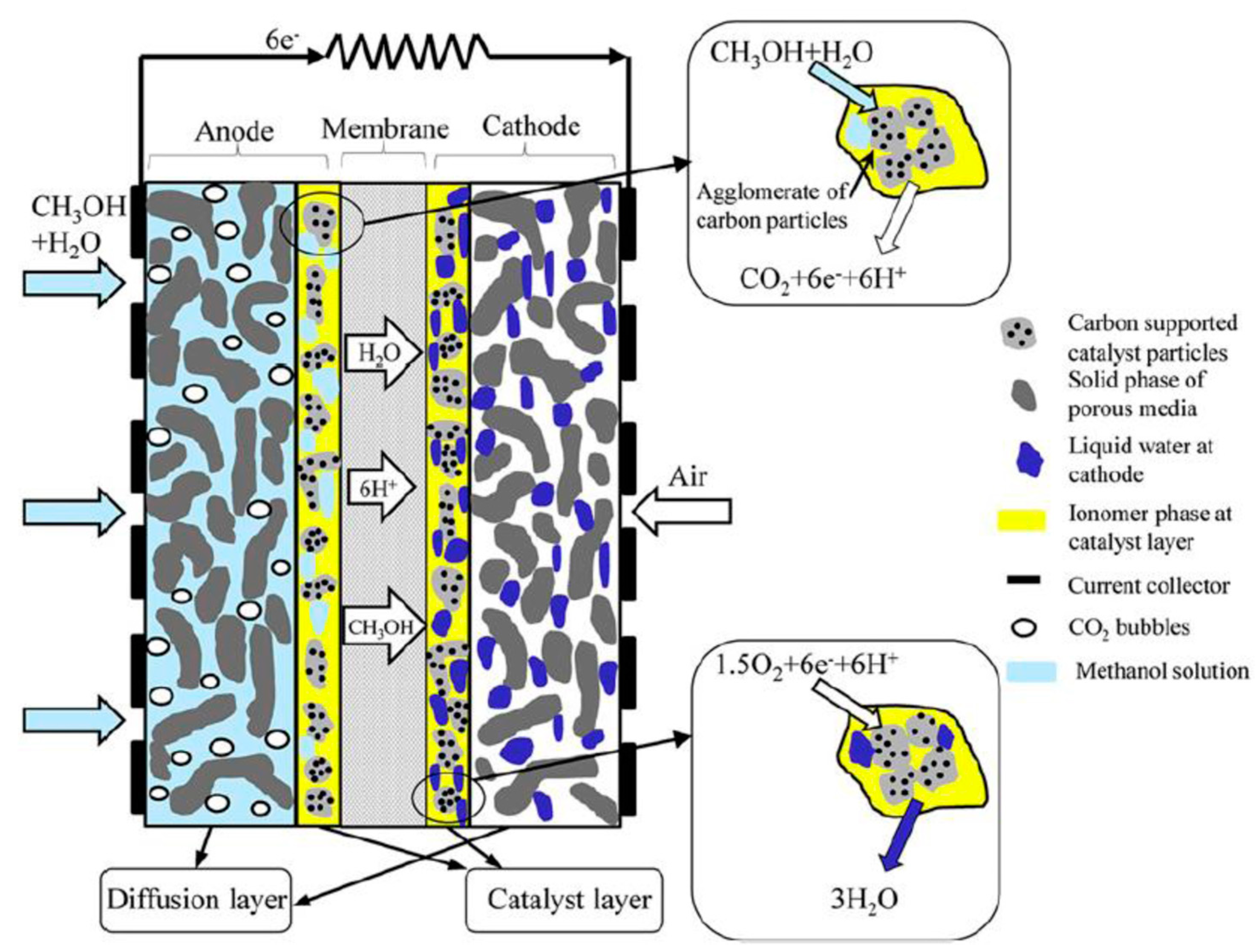
3.2. Methanol in Fuel Cells Applications: DMFCs

A direct methanol fuel cell (DMFC) is classified as a low temperature polymer electrolyte membrane fuel cell supplied by liquid or vapor methanol [58]. Figure 8 shows the schematic diagram of a DMFC, which consists of at least five main porous layers:
(1)
Anode gas diffusion layer (AGDL),
(2)
anode catalyst layer (ACL),
(3)
polymer electrolyte membrane,
(4)
cathode catalyst layer,
(5)
cathode gas diffusion layer.
The methanol fed diffuses through the AGDL towards ACL. Methanol is oxidized to CO2 (Equation (15)) at anode side, allowing six H+ to pass through the membrane and six e across the external circuit, generating electricity. At the cathode side, oxygen from air is reduced to water through the diffusion layer and catalyst layer. The membrane acting as an electrolyte is coated with a catalyst, enhancing the oxidation of methanol at the anode side and the reduction of oxygen at the cathode side.
Anode: CH3OH + H2O → CO2 + 6H+ + 6e
Cathode: 1.5O2 + 6H+ + 6e → 3H2O
Overall: CH3OH + H2O + 1.5O2 → CO2 + 3H2O
DMFCs may be subdivided, depending on the way of fuel and oxidant supply as (a) active, (b) passive and (c) semi-passive.
Conventional active DMFCs operate by means of auxiliary devices, such as fuel feed pump, oxidant supplier, CO2 separator, and fuel cell stacks.
By contrast, passive (air-breathing) DMFCs do not operate by auxiliary devices; hence, they need natural mechanisms, such as convection, capillary, gravity, concentration gradient, or osmosis, to deliver fuel and oxidant. Air is supplied by a breathing mechanism to cathode, while methanol is supplied to anode from a reservoir with a concentration gradient between anode and reservoir [60].
Semi-passive DMFCs represents a particular class able to combine active and passive typologies, attracting a growing attention for the development of compact portable devices with power below 10 W [59]. As an example, a number of big companies, such as Motorola, Toshiba, Samsung, and NEC, were involved in the research, development, and application of passive DMFCs [61]. Among others, Toshiba applied a DMFC as mobile devices, requiring manually filling methanol solution from a cartridge and obtaining oxygen directly from ambient air (palm sized DynarioTM) [62].
Nevertheless, DMFC technology also shows some drawbacks when it comes to its wide diffusion. In particular, even though Nafion utilization has been largely investigated as a polymeric membrane, methanol crossover represents its main negative aspect, being responsible for loss fuel and lower overall cell voltage, limiting the application of DMFCs [63]. Therefore, the research in this field is devoted to analyzing valid options to Nafion membranes to reduce the effects of methanol crossover and to allow a wider utilization and commercialization of DMFCs [64].

4. Methanol Exploitation for Hydrogen Generation

As affirmed by the International Energy Agency, today the world economy is still depending on the exploitation of fossil fuels, such as oil, coal, natural gas, etc. [65]. Consequently, the increment of the environmental pollution due to CO2 emissions and other dangerous gases originating from burning fossil fuels is driving both industry and academia to research new and green technologies, and renewable feedstocks exploitation as well. Hydrogen is currently seen as a clean energy source, playing a relevant role in refining, chemical, and electronic industry [66]. However, hydrogen presents some drawbacks in terms of the difficulties in its storing and transportation, negatively affecting its wider utilization. Consequently, hydrogen generation from an easily transported liquid source may represent a valid option. Methanol is considered an excellent candidate as a hydrogen carrier, showing low toxicity and easy handling. In the following, different industrial processes involving methanol for hydrogen generation are reported and discussed.

4.1. Methanol Decomposition Reaction

According to Equation (21), a methanol decomposition (MD) reaction is an endothermic process able to generate H2 and CO:
CH3OH = CO + 2H2
This process is convenient for recovering industrial heat waste at around 200 °C [67]. It is particularly important to mention that active catalysts based on palladium and prepared by co-precipitation are able, even at temperatures below 200 °C, to catalyze this reaction.

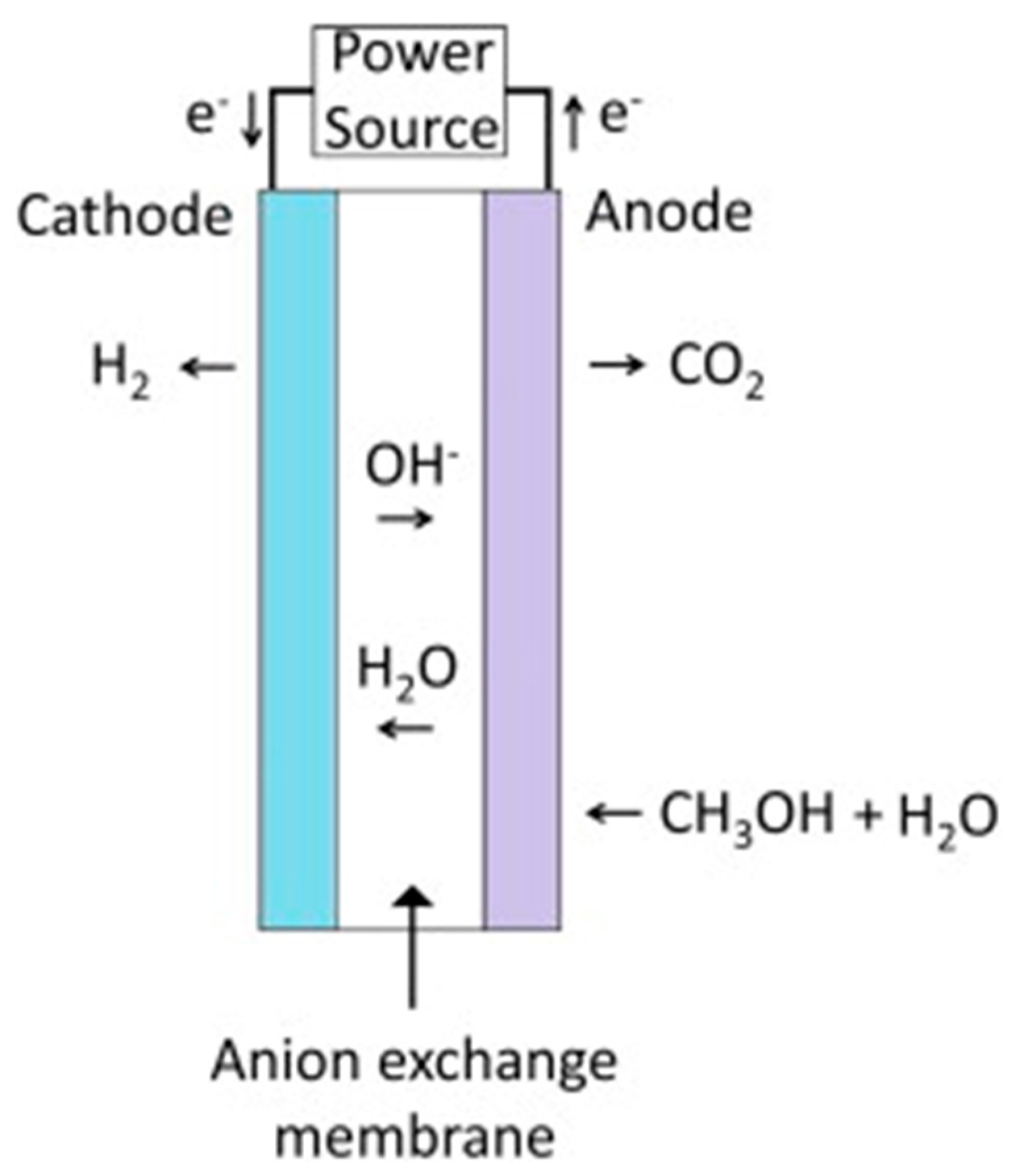
4.2. Methanol–Water Solution Electrolysis

Methanol–water solution electrolysis is another process to generate hydrogen using an electrolytic cell. Commonly, the water electrolysis process represents the best way to produce high grade hydrogen quickly [68]. As a consequence, also using a methanol–water solution, hydrogen may be easily produced with a purity varying between 95% and 97%, even though the theoretical voltage of the system is much lower (0.03 V) than in water electrolysis (1.23 V) [69]. During methanol–water solution electrolysis, hydrogen is generated by applying a direct current to the electrolytic cell, as shown in Figure 9. At the anode side, methanol and water react, generating CO2, protons, and electrons. Protons migrate through the polymeric membrane from the anode to the cathode of the electrolytic cell, while electrons migrate to the cathode through the external circuit containing the direct current power supply. Hydrogen generation from methanol–water solution electrolysis is useful for portable power applications, since the start up and shut down are possible very quickly and at relatively low temperature [68].

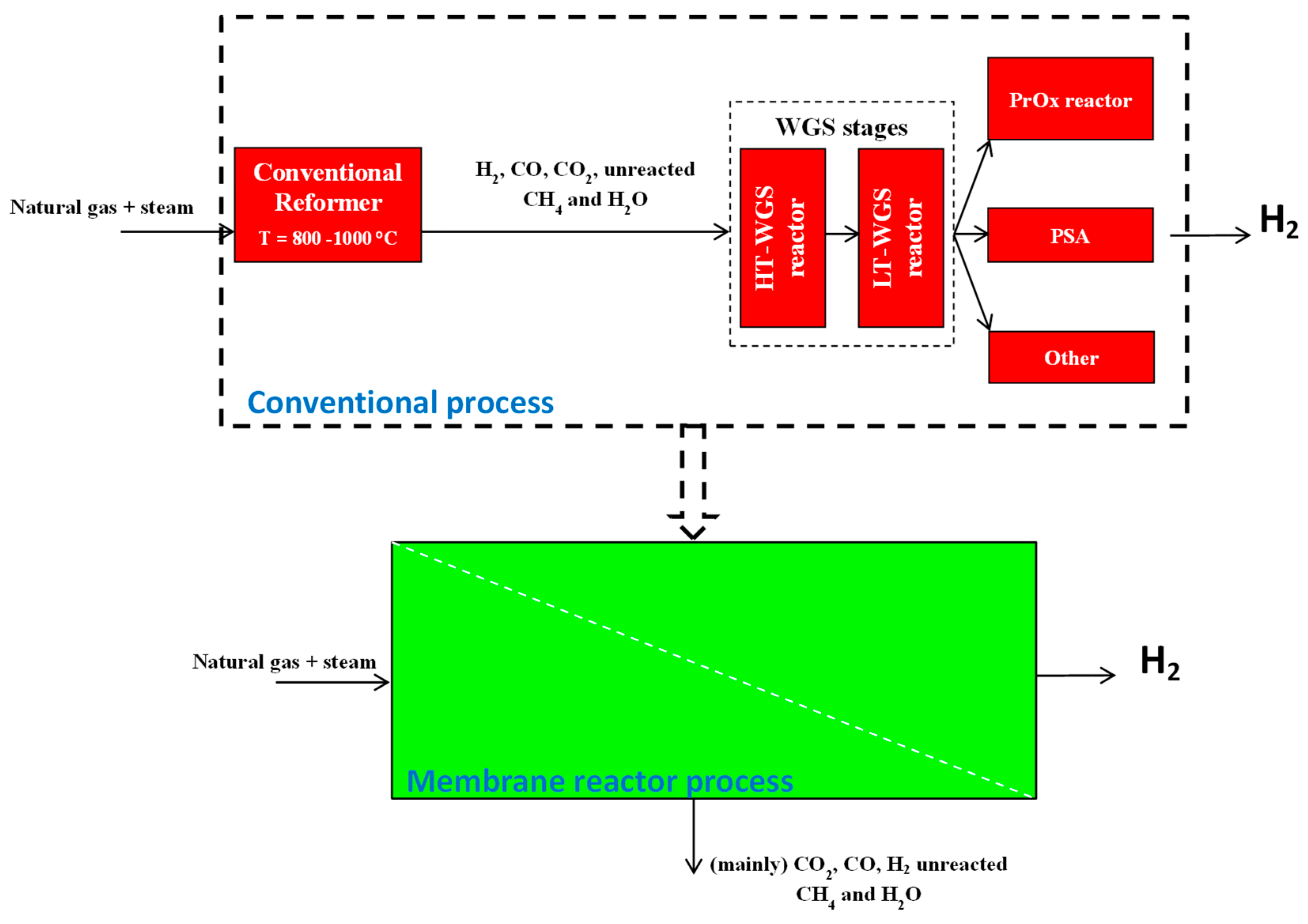
4.3. Methanol Steam Reforming Reaction for Hydrogen Generation

Methanol steam reforming (MSR) has been largely investigated and, currently, the most active catalysts for this process are based on Cu, which are cheap and normally operated in the temperature range from 240 to 260 °C [71].
CH3OH + H2O = CO2 +3H2
Nevertheless, Cu-based catalysts suffer low stability and a pyrophoric nature and, furthermore, are responsible for a significant production of CO. Catalyst deactivation is normally due to sintering, coke deposition, catalyst poisoning (chloride, sulphur), and change in oxidation state. The prevention of coke formation can be done using an excess of water in the feed and, generally, the best results are obtained for molar water/methanol ratio of 1.5:1 [72,73].
Consequently, the research on MSR catalysts which are more active, stable, and responsible for a lower CO production has been greatly pursued. In particular, catalysts able to be operated at around 180 °C should represent a desired goal (indeed, at this temperature, higher stability and low CO production are expected) and, from a thermodynamic point of view, they should show almost complete conversion. In the viewpoint of fuel cells and fuel processors integration, being MSR an endothermic reaction, the reformer reactor could be synergistically coupled with a high temperature proton exchange membrane fuel cell (HT-PEMFC), which works exothermally in the range from 160 to 180 °C.
Apart from Cu-based ones, other catalysts were used for the MSR reaction, in particular those based on palladium, which—compared to nickel, platinum, ruthenium supported on ZnO—showed lower CO production and higher conversion [74]. Additionally, the utilization of bimetallic catalysts seems to be an interesting choice to enhance both activity and selectivity. Among others, the best activity reported was achieved using Pd/Zn and Pd/Ga bimetallic catalysts and the best selectivity with Pd/Cd [75].
Regarding the typology of the MSR reactor design, it is worth noting that it could play a direct role in the reaction performance. Therefore, the reactor design has as a target to be as cheap as possible and to maximize both conversion and selectivity, also taking into account that its process performance is influenced by the flow pattern, velocity profile, pressure drop, and heat transfer [76]. Most of the reactor designs deal with rectilinear channels, pinhole, coil-based, and radial, even though conventional reactors (CRs) are currently tubular due to the complexity and higher costs of realizing the other configurations. Nevertheless, recently, the area of micro fuel processors made it possible and easier to realize further reactor designs and, namely, well-structured flat microreactors, showing benefits over the conventional ones, such as higher surface-to-volume ratio, smaller mean distance of the specific fluid volume to the reactor walls, better heat and matter transfer properties, and flow patterns that fit with the reaction needs. A microreactor is defined as a device that contains micro structured features, with a sub-millimeter dimension, in which chemical reactions are performed in a continuous manner [77]. Compared to the CRs, microreactors present several benefits, such as enhanced heat and matter transfer properties, reduced mean distance of the specific fluid volume to the reactor walls, higher surface-to-volume ratio, etc.
As a further subdivision, it is possible to consider microreactors ranging from 0.1 to 10 cm2 in area and mini-reactors between 10 and 200 cm2 [78]. The latter, however, seem to be more adequate for packed bed applications, better combining the requests of the typical fuel cells size.

4.4. Process Intensification Strategy Applied to MSR Reactors

The MSR reaction originates from a stream containing, in addition to hydrogen, other byproducts, such as CO, CO2, and small amounts of reactants. Therefore, in the viewpoint of combining a fuel processor and PEM fuel cells, hydrogen needs high purity prior to entering in the PEMFC. As for the industrial natural gas steam reforming to produce hydrogen, the reformed stream coming from an MSR reactor should need further hydrogen purification/separation processes, namely water gas shift reaction performed in two reactors operating in series at high and low temperature, partial oxidation reactor to convert CO into CO2, and pressure swing adsorption for separating CO2 from H2. As is well known, the aforementioned stages of hydrogen purification impose heavy costs and negatively affect the overall process efficiency. Thus, according to the principles of Process Intensification Strategy, today it is well recognized that membrane reactor (MR) technology plays an important role as a valid option to the CRs, because it is able to combine the reforming reaction for generating hydrogen and its purification in a single stage without needing further hydrogen separation stages (Figure 10) [79,80].
The concept of MR technology was first introduced in the 1950s, although the utilization of new inorganic materials and the development of high-temperature membrane processes have received much attention in the last three decades. In the field of MR utilization for hydrogen generation, a general subdivision of MR applications can be summarized as reported below:
(a)
Inorganic membrane reactors [79,81];
(b)
self-supported and supported Pd-based membrane reactors [80,82];
(c)
Zeolite membrane reactors [83];
(d)
biomembrane reactors [84];
(e)
photocatalytic membrane reactors [85].
However, most of the open literature dedicated to hydrogen generation via MR technology is devoted to the investigation of inorganic membranes application [82,86,87,88,89]. Currently, the operating modality of membranes housed in a MR can be subdivided as reported below:
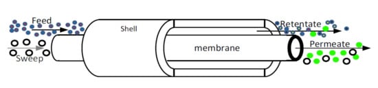
  • Extractor modality: The membrane selectively removes hydrogen from the reaction mixture for permeation.
  • Distributor modality: The membrane allows the controlled addition of hydrogen to the reaction mixture.
  • Contactor modality: The membrane emphasizes the contact within reactants and catalyst.
In the next sub-paragraphs, special attention is dedicated to the characteristics and hydrogen separation/purification performance of palladium-based membranes and their utilization in MRs for producing high grade hydrogen, the latter combining in an integrated/intensified whole process the chemical reaction for transforming methanol via reforming reaction into hydrogen and the hydrogen separation/purification stage in an unique system.

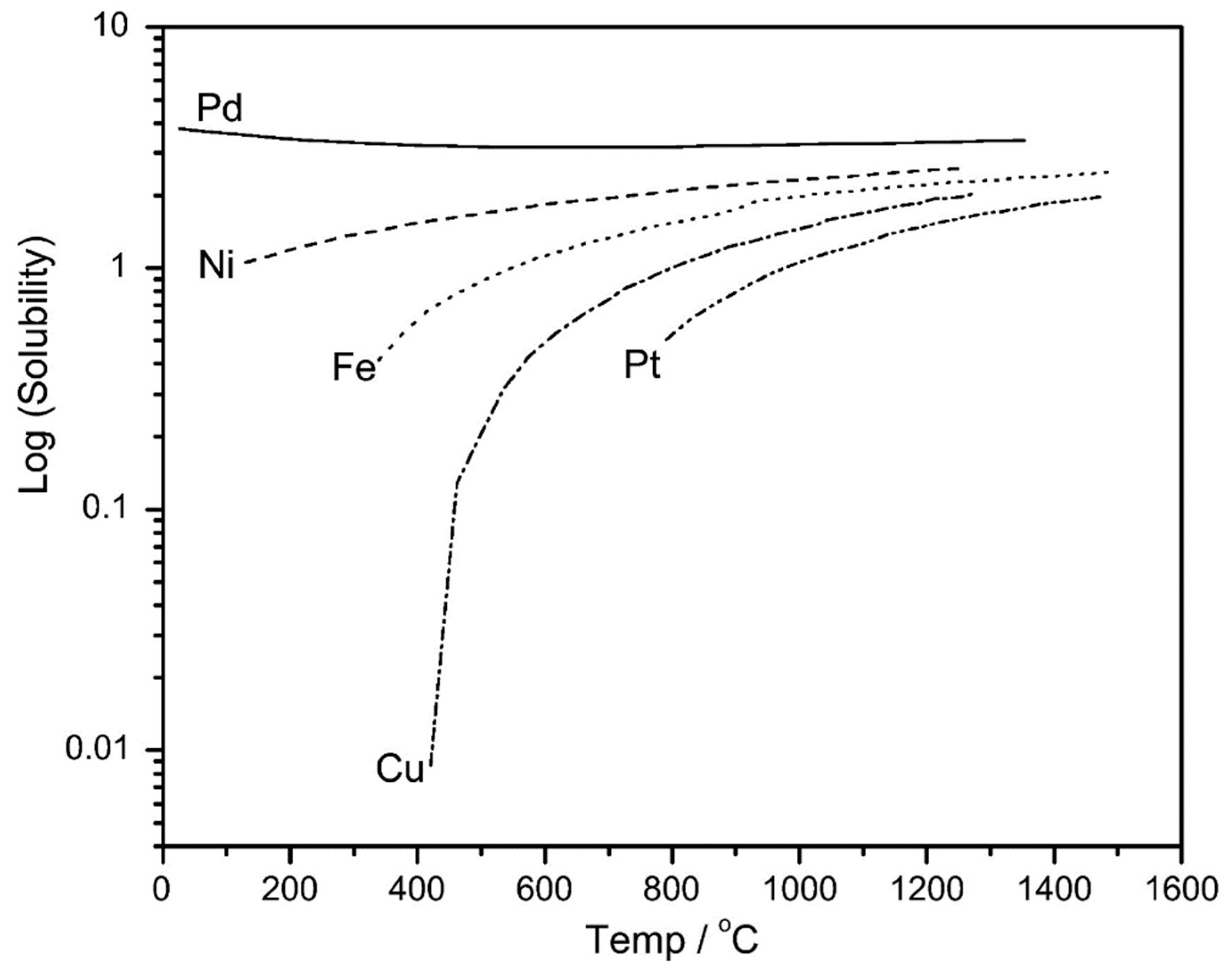
4.5. Applications of Pd-Based Membranes in Membrane Reactors

Metallic-based membranes are presently usually applied in gas separation and in MR applications [79,82]. In particular, palladium and its alloys represent the dominant materials because they possess high H2 solubility, compared to other metallic materials (Figure 11), which makes them useful for preparing H2 perm-selective membranes [89].
The hydrogen transport mechanism through dense Pd and/or Pd-alloy is described by the solution–diffusion, taking place in six steps as reported here below:
  • Hydrogen molecules adsorption from the membrane;
  • dissociation of hydrogen molecules on the membrane surface;
  • reversible dissociative chemisorption of atomic hydrogen;
  • reversible dissolution of atomic hydrogen in the metal lattice of the membrane;
  • diffusion into the metal of atomic hydrogen proceeds from the higher hydrogen pressure to the lower hydrogen membrane side;
  • desorption of recombined atomic hydrogen into molecular form.
Hence, hydrogen permeation through a Pd-based membrane may be described by Equation (23):
J H 2 = P H 2 ( p h p s n p l p s n ) δ
where JH2 is the hydrogen permeating flux, PH2 the hydrogen permeability, δ the thickness of the palladium/palladium alloy layer, phps and plps are the hydrogen partial pressures on the high pressure (feed) and low pressure (permeate) sides, respectively, while “n” is the pressure exponent. The n-value can vary between 0.5 and 1, depending on the rate-determining step among the aforementioned (a)–(g) stages. If the rate-controlling step is represented by bulk diffusion through the palladium layer (c), then n-value is equal to 0.5 and Sieverts law is followed (usually valid for thick palladium films, >5 μm) (Equation (24)) and, consequently, the membrane shows full hydrogen perm-selectivity.
J H 2 = P H 2 ( p h p s 0.5 p l p s 0.5 ) δ
Otherwise, in the case of mass transport to or from the surface (a,g) or dissociative adsorption (b) or associative desorption (e) representing the rate determining stage, n-value becomes 1, indicating that the processes depend linearly on the concentration of molecular hydrogen. Commonly, n = 1 suggests that the permeation through the palladium is very fast (particularly for palladium layer <5 μm).
For thick palladium films, deviation from Sieverts law (n-value > 0.5) can be induced by high hydrogen pressure, decrease in the surface reaction rate after absorption of contaminants, concentration polarization and defects due to pinhole formation. Consequently, hydrogen passes through the Pd-based layer not only for the solution–diffusion mechanism, but also via Knudsen or viscous flow mechanisms (Equation (25)) [89]:
J H 2 T o t a l = 1 1 J H 2 S D + 1 J H 2 K + 1 J H 2 H P
with J H 2 T o t a l representing the total hydrogen permeating through the membrane, J H 2 S D the hydrogen permeating flux via solution/diffusion mechanism, J H 2 K the hydrogen permeating flux via Knudsen mechanism, and J H 2 H P the hydrogen permeating flux via viscous flow/Hagen–Pouiselle mechanism.
Therefore, the combination of a hydrogen perm-selective MR and a reforming process (such as MSR reaction) may produce various synergistic advantages. Indeed, the continuous H2 removal from the reaction side shifts the reaction toward further product formation, allowing it to reach higher conversion (the so-called “shift effect”), while recovering a high grade hydrogen stream in the permeate side, as shown in Figure 12.

4.6. Methanol Steam Reforming Reaction in Membrane Reactors for Hydrogen Generation

In the last two decades, the interest in MSR reaction combined to MRs was reflected in the consistent number of scientific studies present in the open literature, particularly because this combination may offer various benefits for producing hydrogen with respect to the conventional low-pressure systems. Nevertheless, the cost of palladium represents a crucial issue for proposing Pd-based membrane systems as a mature technology, ready for entering in the market. Consequently, taking into account the intrinsic high cost of palladium, the scientific community was oriented to adopt membrane solutions with reduced Pd-content. Table 3 shows some of the most representative results in terms of conversion, hydrogen recovery and purity, operating conditions, etc. related to MSR reaction performed in MRs [90,91,92,93,94,95,96,97,98,99,100,101,102,103,104,105,106]. In particular, this table reports the recent advances in composite Pd-based membranes (a dense, thin layer of Pd and/or its alloy deposited on a porous substrate), even considering not Pd-based membranes in order to highlight benefits and drawbacks between the different solutions.
In detail, Lytkina et al. [90] prepared two dense unsupported Pd–Ag and Pd–Ru membranes via magnetron sputtering, to be housed in a MR for carrying out an MSR reaction at 300 °C and 1:1 feed molar ratio. Reduced methanol conversions were achieved, although reaching a hydrogen recovery of 38% and 18%, respectively, with a purity of around 100%. Saidi [91] performed MSR in a self-supported Pd–Ag (6 μm thick) MR at 300 °C and 2 bar using a Cu/ZnO/Al2O3 catalyst, reaching 98% of conversion, while recovering more than 60% of hydrogen.
Liguori et al. [92] used a supported Pd/PSS MR packed with a CuO/ZnO/Al2O3 catalyst; the composite membrane was prepared by electroless plating deposition (ELP), showing an average metallic layer of around 7 μm. At 330 °C and 2.5 bar, they reached 85% of methanol conversion and 40% of hydrogen recovery, with a purity of around 100%. Another kind of composite membrane (Pd–Ag/TiO2-Al2O3) was used by Basile et al. [93] for performing an MSR reaction. Nevertheless, the presence of defects in the separative layer was responsible for poor performance, although operating at a relatively higher temperature (550 °C): 65 of methanol conversion with a recovered hydrogen stream showing a purity of 72%. Lin et al. [94] used a supported Pd/PSS membrane, prepared by ELP deposition, which showed a metallic layer of 20 μm. In this study, an MSR reaction was performed at 350 °C, 6 bar and 1.2:1 feed molar ratio over a Cu-based catalyst, reaching methanol conversion of 95%, 97% of hydrogen recovered in the permeate stream with a purity of 100%. In another work, Lin’s group [97] used a MR allocating a Pd/PSS membrane with the Pd-layer of 20–25 μm. At 350 °C, a methanol conversion higher than 99% and pure hydrogen recovered in the permeate stream were reached.
Israni and Harold [95] carried out an MSR in a MR housing a thin Pd–Ag/Al2O3 membrane, having a separative layer of around 4 μm, prepared by ELP deposition. At 250 °C and stoichiometric feed molar ratio, they got complete conversion with a hydrogen recovery ranging from 45% at 2.5 bar to 95% at 10 bar, with a hydrogen purity ~100%. Poor results were reached by Rei et al. [96], who used a 20–25 μm thick Pd–Ag/PSS MR. At 240 °C and 10 bar; less than 40% of methanol conversion was obtained, with a poor hydrogen recovery (18%). This probably occurred because the supported membrane showed defects in the separative layer, which negatively affected its perm-selectivity characteristics, determining a low shift effect on MSR reaction, with a consequent low performance. Iulianelli et al. [98] performed an MSR reaction in a self-supported Pd–Ag MR at 300 °C, 3 bar, and feed molar ratio = 3:1 over a CuO/Al2O3/ZnOMgO catalyst. The membrane showed a thickness of 50 μm and was prepared by the cold-rolling technique, allowing a hydrogen recovery of 80%, having a purity of 100%. Also Itoh et al. [99] housed in a MR a self-supported membrane based on Pd–Ru–In (200 μm thick), reaching, at 200 °C and 7 bar, a methanol conversion of 90% and a hydrogen recovery of 24%. The latter result was probably due to the high thickness of the membrane, which was responsible for low hydrogen permeability and, consequently, determined a reduced removal of hydrogen from the reaction to the permeate side. Nevertheless, the recovered hydrogen showed 100% of purity.
Wieland et al. [100] housed different self-supported Pd-alloyed membranes (Pd–Ag, Pd–Cu. and Pd–V–Pd) in MRs for performing an MSR reaction. Among them, the best performance was reached using a Pd–Cu membrane (25 μm thick), which proved the most stable; at 300 °C and 10 bar, they obtained a methanol conversion which was higher than 90%, recovering around 40% of pure hydrogen.
Table 3 does not report only interesting data about the application of Pd-based membranes in MRs, but also alternative and cheaper solutions with respect to palladium, namely carbon and silica membranes. In particular, Sà et al. [101] realized a carbon membrane via the pyrolysis technique, starting from dense cellulose cupra–amonia hollow fibres. It showed relatively low H2/N2 perm-selectivity, but housed in a MR for carrying out an MSR reaction at 200 °C and 1 bar made it possible to reach a conversion of >90% and a hydrogen recovery of >80%. Briceño et al. [102] prepared a supported carbon membrane on a porous ceramic substrate, constituted of TiO2 coated with ZrO2. Hence, different polymeric solutions were deposited as carbon precursors and successively pyrolyzed. The supported carbon membrane was housed in an MR for an MSR reaction and methanol conversion of >50% was obtained at 250 °C and 2 bar, while recovering a hydrogen stream with a purity of ~80% [103]. Zhang et al. [104] allocated in an MR a carbon membrane in a tubular shape with 6-mm of internal diameter and wall thickness of ~20–30 μm, sealed inside a stainless steel tube. During MSR at 250 °C and 2 bar, methanol conversion was around 100%, with a recovery of hydrogen showing 97% of purity.
Lee et al. [105,106] developed two supported silica-based membranes (SiO2/γ–Al2O3/Pt–SiO2/PSS and SiO2/γ–Al2O3) membranes for carrying out an MSR reaction in an MR. The first membrane (SiO2/γ–Al2O3/Pt-SiO2/PSS) was housed in am MR module packed with a Cu–Zn-based catalyst at 230 °C. Complete methanol conversion was reached, although the recovery of hydrogen was very poor (~10%). By contrast, the utilization of the second membrane (SiO2/γ–Al2O3) operated in MR at 260 °C and feed molar ration 3:1 showed a lower conversion (~40%) and hydrogen recovery (5%), even though the purity of the recovered hydrogen was quite high (98%).

4.7. Photocatalytic Membrane Reactors: Methanol Production from CO2 Reduction

Today, photocatalytic membrane reactors (PMRs) are seen as an interesting option for conventional processes in the field of water and air purification and in organic syntheses as well. MR technology shows certain benefits, such as low energy and chemicals consumption, automatic control, and steady/easy operation, making it an ideal subject in several separation processes. Taking these advantages into account, hybrid processes combining photocatalysis and membrane operations are able to achieve a synergistic effect, minimizing environmental and economic concerns. PMRs are then considered a green technology, because they guarantee the safety of the photocatalyst used and operate at mild conditions and in continuous configuration, in which catalyst recovery, reaction, and products separation take place simultaneously, with consequent time- and cost-saving [107,108]. Furthermore, the possibility to combine the photocatalytic reactions with solar light utilization proved particularly attractive, making this process really interesting for future industrial applications.
In this scientific field, CO2 transformation into organic molecules like methanol has proven to be very attracting, because it is potentially useful for depleting CO2 emissions from industrial streams, obtaining added-value products, and constituting a great goal for the scientific community. In this regard, CO2 reduction by using TiO2 as a photocatalyst both in liquid and in gas phase was the main subject of various scientific studies [109,110,111]. Among them, Sellaro et al. [109] performed CO2 reduction into methanol in a PMR operated at mild conditions, in which TiO2 was immobilized in Nafion membranes. The reaction was performed under UV light in liquid phase using H2O as a reducing agent by housing the membranes in a flat sheet membrane module equipped with a quartz window to allow the irradiation. The proposed membrane configuration associated to the continuous flow modality made the removal of methanol from the PMR possible, avoiding its overoxidation.
Pathak et al. [110] allocated a porous optically transparent ionomer Nafion membrane embedded with TiO2 nanoparticles in a PMR to carry out the photocatalytic reduction of supercritical CO2. They found that, among methanol, ethanol, and formaldehyde, their composition was determined by the flow rate and by the weight of TiO2 used.
More recently, Pomilla et al. [111] proposed CO2 reduction into fuels in a continuous PMR housing a Nafion membrane with embedded exfoliated C3N4. The PMR converted CO2 in various products, such as methanol, ethanol, acetone, etc., with compositions strongly dependent on H2O/CO2 feed molar ratio and residence time.
However, the knowledge about the fundamentals of photocatalysis represents a crucial aspect to better understanding all the parameters able to affect the process under investigation. In the near future, the development of new photocatalysts coupled with PMR utilization will constitute a critical task, keeping in mind clearly that a sustainable process may be pursued when a PMR is combined with the sun as a cheap and clean source of light.

5. Recent European Projects Involving Methanol Production, Utilization, and Transformation

The European scientific community as well as the European Commission have concretely contributed in recent years to the development of a methanol platform, in which the main subject of the various European Projects is methanol as a source and/or intermediate for its transformation in other added-value products. These European actions have been realized with the financial support of various scientific projects, briefly illustrated in this paragraph.
“MefCO2—Methanol fuel from CO2” has been funded by the European Commission within Horizon 2020 (2014–2020) projects and is coordinated by I-Deals/Every Group (Spain). It aims to produce green methanol as an energy vector from captured CO2 and hydrogen produced using renewable energy surplus. The technology is being designed in a modular intermediate scale, with the aim of being able to adapt it to varying plant sizes and gas composition.
“WOODSPIRIT” was a big demonstration project developed by the company BioMCN (The Netherlands) for the production of biomethanol, for use as a transportation fuel additive. The consortium got 199 million euros under the first call for proposals of the NER300 funding EU program for innovative low-carbon technologies, demonstrating the production of biomethanol in a large commercial scale (413,000 t/y) using biomass torrefaction and entrained flow gasification as the new core technologies. The aim of this project was to utilize the biomethanol as a petrol additive for partial replacement of mineral fuel.
“BEINGENERGY—Integrated low temperature methanol steam reforming and high temperature polymer electrolyte membrane fuel cell” has been a FP7/JTI-CP-FCH—Joint Technology Initiatives—Collaborative Project (FCH), realized in the period between 2012 and 2016 and coordinated by University Porto (Portugal). This project was aimed at proposing a power supply comprising a methanol steam reformer and high temperature polymer electrolyte membrane fuel cell (HT-PEMFC) operating at the same temperature. Additionally, it proposed the application of the Pd-based MR technology for single-stage hydrogen production and of an ionic-liquid-supported polymer membrane selective for CO2 removal from reformate streams operating at up to 200 °C.
In the same field of application, The European FP7 project “LIQUID POWER” was developed in the period from 2011–2016 and coordinated by Dantherm Power (Denmark), with the aim of developing a new generation of fuel cell systems for backup power markets and for material handling vehicles, as well as for developing new innovative hydrogen supply methods for onsite methanol reforming.
“CEOPS—CO2 loop for Energy storage and conversion to Organic chemistry Processes through advanced catalytic Systems” has been an NMP–FP7 European project devoted to a sustainable approach for the production of methanol from CO2, acting as a precursor for fine chemicals products. It was realized between 2013 and 2016 and was coordinated by the CEA Institute (France). The concept of the project was concentrated on the development of two chemical pathways based on: (1) CO2 to methane conversion, realized with advanced catalysts to promote the efficiency of the electro–catalytic process at the point of CO2 emission (cement works); (2) direct conversion of methane to methanol, realized with advanced catalysts to promote the efficiency of the direct pathway instead of using the current pathway consisting of a steam reforming of CH4, which represents 60–70% of cost of production of current methanol, followed by the CO hydrogenation reaction.
“NEMESIS2+—New Method for Superior Integrated Hydrogen Generation System 2+” has been an FCH–JU European Project developed from 2012 to 2015 and coordinated by German Aerospace Center—DLR e.V. (Germany). The principal objective of this project was the development of a small-scale hydrogen generator capable of producing 50 m3·h−1 hydrogen (purity: 5.0) from biodiesel and diesel. In detail, methanol was used as a reactant to convert triglyceride into Fatty Acid Methyl Ester, which currently represents biodiesel.
“SUPER METHANOL—Reforming of Crude Glycerine in Supercritical Water to Produce Methanol for Re-Use in Biodiesel Plants” was a CP–FP small- or medium-scale focused research project, developed between 2008 and 2011 and led by B.T.G. Biomass Technology Group BV (The Netherlands). The objective was to produce methanol from crude glycerine, reusing it in the biodiesel plant while improving the energy balance, carbon performance, sustainability, and overall economics of biodiesel production. In practice, the consortium was able to perform the reform of glycerine in supercritical water, and to produce a synthesis gas suitable for direct once-through methanol synthesis.
“METAPU—Validation of a Renewable Methanol-based Auxiliary Power System for Commercial Vessels” was an FP6–SUSTDEV-3—Global Change and Ecosystems EU project coordinated by Wärtsilä Corporation (Finland). This project investigated, in the period from 2006–2010, the use of methanol and solid oxide fuel cell technology for shipping. In particular, it allowed to successfully propose methanol utilization for fuel onboard ships, whereas international regulations permit only the carriage of methanol as cargo.

6. Conclusions and Future Trends

A comprehensive review on methanol production and application was reported in this work, paying particular attention to the exploitation of methanol through MR technology for hydrogen generation. In this work, it was clearly represented how methanol plays a key role as one of the most significative and versatile molecules, with interesting potentials as easily transportable fuel and in the chemical industry (as a solvent and as a C1 building block for producing intermediates and synthetic hydrocarbons) or as a convenient energy carrier for hydrogen generation. Indeed, methanol seems to be the most significant product of the future, both for green chemistry development and as a hydrogen carrier. In particular, the review highlighted the most important methanol production cycles coming from biomass and/or CO2, the latter case being particularly important in the viewpoint of the minimization of GHGs production and as a solution to global warming.
The second part of the review was related to the hydrogen generation via reforming reactions involving methanol as well as to the role of methanol in DMFC applications. Furthermore, the principles of the Process Intensification Strategy and the consequent application of MR technology were also discussed. Last but not least, a panoramic view on the most significative European Project developed in the last ten years about methanol was also added.

Funding

This research received no external funding.

Conflicts of Interest

The authors declare no conflict of interest.

List of Acronyms

ACLAnode Catalyst Layer
AGDLAnode Gas Diffusion Layer
AMRAutothermal Methane Reforming
BASFBadischeAnilin und Soda Fabrik
CRConventional Reactor
DMEDiMethyl Ether
DMFCDirect Methanol Fuel Cell
ELPElectroless Plating
GHGGreenhouse Gases
HTHigh Temperature
ICIImperial Chemical Industries
MDMethanol Decomposition
MRMembrane Reactor
MSRMethanol Steam Reforming
MTBEMethyl Tertiary Butyl Ether
NCCCNational Carbon Capture Center
PEMProton Exchange Membrane
PMRPhotocatalytic Membrane Reactor
POMPartial Oxidation of Methanol
SMRSteam Methane Reforming
WGSWater-Gas Shift

References

  1. Dalena, F.; Senatore, A.; Tursi, A.; Basile, A. Bioenergy production from second and third generation feedstocks. In Bioenergy Systems for the Future; Dalena, F., Basile, A., Rossi, C., Eds.; Prospects for Biofuels and Biohydrogen; Elseiver Publishing: London, UK, 2017. [Google Scholar]
  2. Dalena, F.; Senatore, A.; Marino, A.; Gordano, A.; Basile, M.; Basile, A. Methanol Production and Application. An overview. In The Science and Engineering of Methanol; Basile, A., Dalena, F., Eds.; Elsevier Publishing: London, UK, 2017; ISBN 978-0-444-63903-5. [Google Scholar]
  3. The Methanol Industry. Available online: https://www.methanol.org/the-methanol-industry/ (accessed on 17 October 2018).
  4. Cifre, P.G.; Badr, O. Renewable hydrogen utilisation for the production of methanol. Energy Convers. Manag. 2007, 48, 519–527. [Google Scholar] [CrossRef] [Green Version]
  5. Hughes, D.O. Methanol: The chemical of the future. Chemsa 1980, 6, 180–182. [Google Scholar]
  6. Ali, K.A.; Abdullah, A.Z.; Mohamed, A.R. Recent development in catalytic technologies for methanol synthesis from renewable sources: A critical review. Renew. Sustain. Energy Rev. 2015, 44, 508–518. [Google Scholar] [CrossRef]
  7. Khadzhiev, S.N.; Kolesnichenko, N.V.; Ezhova, N.N. Slurry technology in methanol synthesis (Review). Pet. Chem. 2016, 56, 77–95. [Google Scholar] [CrossRef]
  8. Sabatier, P. How I have been led to the direct hydrogenation method by metallic catalysts. Ind. Eng. Chem. 1926, 18, 1005–1008. [Google Scholar] [CrossRef]
  9. Tijm, P.J.A.; Waller, F.J.; Browna, D.M. Methanol technology developments for the new millennium. Appl. Catal. A 2001, 221, 275–282. [Google Scholar] [CrossRef]
  10. Couper, J.R.; Beasley, T.; Penney, W.R. The Chemical Process Industries Infrastructure: Function and Economics; CRC Press: Boca Raton, FL, USA, 2000; pp. 1–644. ISBN 9780824704353. [Google Scholar]
  11. Natta, G. Synthesis of Methanol, Ch. 8 of Catalysis; Emmett, P.H., Ed.; Reinhold Publishing Corporation: New York, NY, USA, 1955; Volume 3, pp. 1–363. [Google Scholar]
  12. Zhen, X.; Wang, Y. An Overview of methanol as an internal combustion engine fuel. Renew. Sustain. Energy Rev. 2015, 52, 477–493. [Google Scholar] [CrossRef]
  13. Gumber, S.; Gurumoorthy, A.V.P. Methanol Economy Versus Hydrogen Economy, in Methanol: Science and Engineering; Basile, A., Dalena, F., Eds.; Elsevier: Amsterdam, The Netherlands, 2018; pp. 661–674. ISBN 978-044463903-5. [Google Scholar]
  14. Iulianelli, A.; Ribeirinha, P.; Mendes, A.; Basile, A. Methanol steam reforming for hydrogen generation via conventional and membrane reactors: A review. Renew. Sustain. Energy Rev. 2014, 29, 355–368. [Google Scholar] [CrossRef]
  15. Yong, S.T.; Ooi, C.W.; Chai, S.P.; Wu, X.S. Review of methanol reforming-Cu-based catalysts, surface reaction mechanisms, and reaction schemes. Int. J. Hydrogen Energy 2013, 38, 9541–9552. [Google Scholar] [CrossRef]
  16. Kapran, A.Y.; Orlyk, S.M. Hydrogen production in methanol reforming on modified copper–zinc catalysts: A review. Theor. Exp. Chem. 2016, 53, 1–16. [Google Scholar] [CrossRef]
  17. Xu, X.; Shuai, K.; Xu, B. Review on copper and palladium based catalysts for methanol steam reforming to produce hydrogen. Catalysts 2017, 7, 183. [Google Scholar] [CrossRef]
  18. Iulianelli, A.; Longo, T.; Liguori, S.; Basile, A. Production of hydrogen via glycerol steam reforming in a Pd-Ag membrane reactor over Co-Al2O3 catalyst. Asia-Pac. J. Chem. Eng. 2010, 5, 138–145. [Google Scholar] [CrossRef]
  19. Madej-Lachowska, M.; Kulawska, M.; Słoczyński, J. Methanol as a high purity hydrogen source for fuel cells: A brief review of catalysts and rate expressions. Chem. Process Eng. 2017, 38, 147–162. [Google Scholar] [CrossRef]
  20. Chen, Z.; Huang, Y.; He, X. Theoretical study of the mechanism of methanol steam reforming over Pd/ZnO. Prog. Chem. 2012, 24, 873–878. [Google Scholar]
  21. Bertau, M.; Wernicke, H.J.; Schmidt, F. Methanol Utilization Technologies. In Methanol: The Basic Chemical and Energy Feedstock of the Future; Bertau, M., Offermanns, H., Plass, L., Schmidt, F., Wernicke, H.J., Eds.; Springer: Berlin, Germany, 2014; pp. 1–677. ISBN 978-3-642-39709-7. [Google Scholar]
  22. Fiedler, E.; Grossmann, G.; Kersebohm, D.B.; Weiss, G.; Witte, C. Methanol. In Ullmann’s Encyclopedia of Industrial Chemistry; Wiley-VCH Verlag GmbH & Co. KgaA: Weinheim, Germany, 2000. [Google Scholar]
  23. Da Silva, M.J. Synthesis of methanol from methane: Challenges and advances on the multi-step (syngas) and one-step routes (DMTM). Fuel Process Technol. 2016, 145, 42–61. [Google Scholar] [CrossRef]
  24. Li, J.; Ma, X.; Liu, H.; Zhang, X. Life cycle assessment and economic analysis of methanol production from coke oven gas compared with coal and natural gas routes. J. Clean. Prod. 2018, 185, 299–308. [Google Scholar] [CrossRef]
  25. Wilkinson, S.K.; Van De Water, L.G.A.; Miller, B.; Simmons, M.J.H.; Stitt, E.H.; Watson, M.J. Understanding the generation of methanol synthesis and water gas shift activity over copper-based catalysts—A spatially resolved experimental kinetic study using steady and non-steady state operation under CO/CO2/H2feeds. J. Catal. 2016, 337, 208–220. [Google Scholar] [CrossRef]
  26. Mittasch, A.; Pier, M. Synthetic Manufacture of Methanol. U.S. Patent 1569775, 12 January 1926. [Google Scholar]
  27. Brown, N.J.; García-Trenco, A.; Weiner, J.; White, E.R.; Allinson, M.; Chen, Y.; Peter, P.W.; Emma, K.G.; Klaus, H.; Milo, S.P.S.; et al. From organometallic zinc and copper complexes to highly active colloidal catalysts for the conversion of CO2 to methanol. ACS Catal. 2015, 5, 2895–2902. [Google Scholar] [CrossRef]
  28. Sun, Y.; Chen, L.; Bao, Y.; Zhang, Y.; Wang, J.; Fu, M.; Wu, J.; Ye, D. The applications of morphology controlled ZnO in catalysis. Catalysts 2016, 6, 188. [Google Scholar] [CrossRef]
  29. Zhang, X.; Zhong, L.; Guo, Q.; Fan, H.; Zheng, H.; Xie, K. Influence of the calcination on the activity and stability of the Cu/ZnO/Al2O3 catalyst in liquid phase methanol synthesis. Fuel 2010, 89, 1348–1352. [Google Scholar] [CrossRef]
  30. Van Bennekom, J.G.; Venderbosch, R.H.; Winkelman, J.G.M.; Wilbers, E.; Assink, D.; Lemmens, K.P.J.; Heeres, H.J. Methanol synthesis beyond chemical equilibrium. Chem. Eng. Sci. 2013, 87, 204–208. [Google Scholar] [CrossRef]
  31. Van der Stelt, M.J.C.; Gerhauser, H.; Kiel, J.H.A.; Ptasinski, K.J. Biomass upgrading by torrefaction for the production of biofuels: A Review. Biomass Bioenergy 2011, 35, 3748–3762. [Google Scholar] [CrossRef]
  32. Wilhelm, D.J.; Simbeck, D.R.; Karp, A.D.; Dickenson, R.L. Syngas production for gas-to-liquids applications: Technologies, issues and outlook. Fuel Process. Technol. 2011, 71, 139–148. [Google Scholar] [CrossRef]
  33. Zhao, Z.; Lakshminarayanan, N.; Swartz, S.L.; Arkenberg, G.B.; Felix, L.G.; Slimane, R.B.; Choi, C.C.; Ozkan, U.S. Characterization of olivine-supported nickel silicate as potential catalysts for tar removal from biomass gasification. Appl. Catal. A 2015, 489, 42–50. [Google Scholar] [CrossRef] [Green Version]
  34. Sá, S.; Silva, H.; Brandão, L.; Sousa, J.M.; Mendes, A. Catalysts for methanol steam reforming—A review. Appl. Catal. B Environ. 2010, 99, 43–57. [Google Scholar] [CrossRef]
  35. Peppley, B.A.; Amphlett, J.C.; Kearns, L.M.; Mann, R.F. Methanol steam reforming on Cu/ZnO/Al2O3 catalysts. Part. 2. A comprehensive kinetic model. Appl. Catal. A 1999, 179, 31–49. [Google Scholar] [CrossRef]
  36. Phongamwong, T.; Chantaprasertporn, U.; Witoon, T.; Numpilai, T.; Poo-Arporn, Y.; Limphirat, W.; Waleeporn, D.; Peerapan, D. Metta Chareonpanich, Limtrakul, J. CO2 hydrogenation to methanol over CuO–ZnO–ZrO2–SiO2 catalysts: Effects of SiO2 contents. Chem. Eng. J. 2017, 316, 692–703. [Google Scholar] [CrossRef]
  37. Tisseraud, C.; Comminges, C.; Belin, T.; Ahouari, H.; Soualah, A.; Pouilloux, Y.; Le Valant, A. The Cu–ZnO synergy in methanol synthesis from CO2, Part 2: Origin of the methanol and CO selectivities explained by experimental studies and a sphere contact quantification model in randomly packed binary mixtures on Cu–ZnO coprecipitate catalysts. J. Catal. 2015, 330, 533–544. [Google Scholar] [CrossRef]
  38. Tisseraud, C.; Comminges, C.; Habrioux, A.; Pronier, S.; Pouilloux, Y.; Le Valant, A. Cu-ZnO catalysts for CO2 hydrogenation to methanol: Morphology change induced by ZnO lixiviation and its impact on the active phase formation. Mol. Catal. 2018, 446, 98–105. [Google Scholar] [CrossRef]
  39. Liao, F.; Huang, Y.; Ge, J.; Zheng, W.; Tedsree, K.; Collier, P.; Hong, X.; Tsang, S.C. Morphology-Dependent Interactions of ZnO with Cu Nanoparticles at the Materials’ Interface in Selective Hydrogenation of CO2 to CH3OH. Angew. Chem. 2011, 50, 2162–2165. [Google Scholar] [CrossRef] [PubMed]
  40. Shabangu, S.; Woolf, D.; Fisher, E.M.; Angenent, L.T.; Lehmann, J. Techno-economic assessment of biomass slow pyrolysis into different biochar and methanol concepts. Fuel 2017, 117, 742–748. [Google Scholar] [CrossRef]
  41. Kempegowda, R.S.; Pannir Selvam, P.V.; Skreiberg, Ø.; Tran, K.-Q. Process synthesis and economics of combined biomethanol and CHP energy production derived from biomass wastes. J. Chem. Technol. Biotechnol. 2012, 87, 897–902. [Google Scholar] [CrossRef]
  42. Marie-Rose, S.C.; Chornet, E.; Lynch, D.; Lavoie, J.-M. From biomass-rich residues into fuels and green chemicals via gasification and catalytic synthesis. WIT Trans. Ecol. Environ. 2011, 143, 123–132. [Google Scholar] [Green Version]
  43. Dalena, F.; Basile, A. Bioalcohols Production. In Alcohols and Bioalcohols: Characteristics, Production and Uses; Dalena, F., Basile, A., Eds.; Nova Science Publishers: Hauppauge, NY, USA, 2014; pp. 1–22. ISBN 978-1-63321-934-2. [Google Scholar]
  44. Dai, J.; Saayman, J.; Grace, J.R.; Ellis, N. Gasification of woody biomass. Ann. Rev. Chem. Biomol. Eng. 2015, 6, 77–99. [Google Scholar] [CrossRef] [PubMed]
  45. Trop, P.; Anicic, B.; Goricanec, D. Production of methanol from a mixture of torrefied biomass and coal. Energy 2014, 77, 125–132. [Google Scholar] [CrossRef]
  46. Shahbaz, M.; Yusup, S.; Inayat, A.; Patrick, D.O.; Ammar, M. The influence of catalysts in biomass steam gasification and catalytic potential of coal bottom ash in biomass steam gasification: A review. Renew. Sustain. Energy Rev. 2017, 73, 468–476. [Google Scholar] [CrossRef]
  47. Basile, A.; Blasi, A.; Fiorenza, G.; Iulianelli, A.; Longo, T.; Calabrò, V. Membrane and Membrane Reactor Technologies in the Treatment of Syngas Streams Produced from Gasification Processes. In Gasification: Chemistry, Processes and Applications; Baker, M.D., Ed.; Nova Science Publishers: Hauppauge, NY, USA, 2011; pp. 139–174. ISBN 978-1-61209-681-0. [Google Scholar]
  48. Korens, N.; Simbeck, D.R.; Wilhelm, D.J. Process Screening Analysis of Alternative Gas Treating and Sulphur Removal for Gasification; Final Report by SFA Pacific Inc. Engineering & Economic Consultants, DOE/NETL Task Order No. 739656-00100; SFA Pacific Inc.: Mountain View, CA, USA, 2002; pp. 1–104. Available online: https://www.netl.doe.gov/File%20Library/Research/Coal/energy%20systems/gasification/pubs/SFA-Pacific_Process-Screening-Analysis_Dec-2002.pdf (accessed on 17 October 2018).
  49. Stangeland, K.; Li, H.; Yu, Z. Thermodynamic analysis of chemical and phase equilibria in CO2 hydrogenation to methanol, dimethyl ether, and higher alcohols. Ind. Eng. Chem. Res. 2018, 57, 4081–4094. [Google Scholar] [CrossRef]
  50. Li, W.; Wang, H.; Jiang, X.; Zhu, J.; Liu, Z.; Guo, X.; Song, C. A short review of recent advances in CO2 hydrogenation to hydrocarbons over heterogeneous catalysts. RSC Adv. 2018, 8, 7651–7669. [Google Scholar] [CrossRef]
  51. Centi, G.; Perathoner, S. Opportunities and prospects in the chemical recycling of carbon dioxide to fuels. Catal. Today 2009, 148, 191–205. [Google Scholar] [CrossRef]
  52. Liu, J.; Jin, F.; Fan, M.; Zhu, L.; Tang, C.; Chang, R.; Jia, Q.; Li, Q. Production of high-pure hydrogen by an integrated catalytic process: Comparison of different lignocellulosic biomasses and three major components. Fuel 2018, 226, 322–330. [Google Scholar] [CrossRef]
  53. Global Methanol Demand Growth Driven by Methanol to Olefins as Chinese Thirst for chemical Supply Grows, IHS Markit Says, IHS Online Newsroom. Available online: http://news.ihsmarkit.com (accessed on 17 October 2018).
  54. Lerner, A.; Brear, M.J.; Lacey, J.S.; Gordon, R.L.; Webley, P.A. Life cycle analysis (LCA) of low emission methanol and di-methyl ether (DME) derived from natural gas. Fuel 2018, 220, 871–878. [Google Scholar] [CrossRef]
  55. Hosseininejad, S.; Afacan, A.; Hayes, R.E. Catalytic and kinetic study of methanol dehydration to dimethyl ether. Chem. Eng. Res. Des. 2012, 90, 825–833. [Google Scholar] [CrossRef]
  56. Semelsberger, T.A.; Borup, R.L.; Greene, H.L. Dimethyl ether (DME) as an alternative fuel. J. Power Sources 2006, 156, 497–511. [Google Scholar] [CrossRef]
  57. Ohno, Y.; Yoshida, M.; Shikada, T.; Inokoshi, O.; Ogawa, T.; Inoue, N. New Direct Synthesis Technology for DME (Dimethyl Ether) and its Application Technology; JFE Technical Report No. 8; JFE: Tokyo, Japan, 2006; pp. 34–40. Available online: http://www.jfe-steel.co.jp/en/research/report/008/pdf/008-06.pdf (accessed on 17 October 2018).
  58. Bahrami, H.; Faghri, A. Review and advances of direct methanol fuel cells: Part II: Modeling and numerical simulation. J. Power Sources 2013, 230, 303–320. [Google Scholar] [CrossRef]
  59. Radenahmad, N.; Afif, A.; Petra, P.I.; Rahman, S.M.H.; Eriksson, S.-G.; Azad, A.K. Proton-conducting electrolytes for direct methanol and direct urea fuel cells—A state-of-the-art review. Renew. Sustain. Energy Rev. 2016, 57, 1347–1358. [Google Scholar] [CrossRef]
  60. Mekhilef, S.; Saidur, R.; Safari, A. Comparative study of different fuel cell technologies. Renew. Sustain. Energy Rev. 2012, 16, 981–989. [Google Scholar] [CrossRef]
  61. Liu, J.G.; Zhao, T.S.; Chen, R.; Wong, C.W. The effect of methanol concentration on the performance of a passive DMFC. Electrochem. Commun. 2005, 7, 288–294. [Google Scholar] [CrossRef]
  62. Toshiba Launches Direct Methanol Fuel Cell in Japan as External Power for Mobile Electronic Devices. Available online: https://www.toshiba.co.jp/about/press/2009_10/pr2201.htm (accessed on 17 October 2018).
  63. Iulianelli, A.; Gugliuzza, A.; Clarizia, G.; Ebrasu, D.; Bevilacqua, A.; Trotta, F.; Basile, A. Sulfonation of PEEK-WC polymer via chloro-sulfonic acid for potential PEM fuel cell applications. Int. J. Hydrogen Energy 2010, 35, 12688–12695. [Google Scholar] [CrossRef]
  64. Iulianelli, A.; Basile, A. Sulfonated PEEK-based polymers in PEMFC and DMFC applications: A review. Int. J. Hydrogen Energy 2012, 37, 15241–15255. [Google Scholar] [CrossRef]
  65. Basile, A.; Iulianelli, A. Advances in Hydrogen Production, Storage and Distribution, 1st ed.; Elsevier Science: Amsterdam, The Netherlands, 2014; pp. 1–574. ISBN 978-0-85709-768-2. [Google Scholar]
  66. International Energy Agency (IEA). Energy Technology Perspectives 2014. Available online: https://www.iea.org/publications/freepublications/publication/EnergyTechnologyPerspectives_ES.pdf (accessed on 17 October 2018).
  67. Usami, Y.; Kagawa, K.; Kawazoe, M.; Matsumura, Y.; Sakurai, H.; Haruta, M. Catalytic methanol decomposition at low temperatures over palladium supported on metal oxides. Appl. Catal. A 1998, 171, 123–130. [Google Scholar] [CrossRef]
  68. Menia, S.; Tebibel, H.; Lassouane, L.; Khellaf, A.; Nouicer, I. Hydrogen production by methanol aqueous electrolysis using photovoltaic energy: Algerian potential. Int. J. Hydrogen Energy 2017, 42, 8661–8669. [Google Scholar] [CrossRef]
  69. Take, T.; Tsurutani, K.; Umeda, M. Hydrogen production by methanol-water solution electrolysis. J. Power Sources 2007, 164, 9–16. [Google Scholar] [CrossRef]
  70. Tuomi, S.; Santasalo-Aarnio, A.; Kanninen, P.; Kallio, T. Hydrogen production by methanol–water solution electrolysis with an alkaline membrane cell. J. Power Sources 2013, 229, 32–35. [Google Scholar] [CrossRef]
  71. Mastalir, Á.; Patzkó, Á.; Frank, B.; Schomäcker, R.; Ressler, T.; Schlögl, R. Steam reforming of methanol over Cu/ZnO/Al2O3 modified with hydrotalcites. Catal. Commun. 2007, 8, 1684–1690. [Google Scholar] [CrossRef]
  72. Liu, Y.; Hayakawa, T.; Tsunoda, T.; Suzuki, K.; Hamakawa, S.; Murata, K.; Shiozaki, R.; Ishii, T.; Kumagai, M. Steam reforming of methanol over Cu/CeO2 catalysts studied in comparison with Cu/ZnO and Cu/Zn(Al)O catalysts. Top. Catal. 2003, 22, 205–213. [Google Scholar] [CrossRef]
  73. Lindström, B.; Pettersson, L.J.; Menon, P.G. Activity and Characterization of Cu/Zn, Cu/Cr and Cu/Zr on γ-Alumina for methanol reforming for fuel cell vehicles. Appl. Catal. A 2002, 234, 111–125. [Google Scholar] [CrossRef]
  74. Iwasa, N.; Mayanagi, T.; Nomura, W.; Arai, M.; Takezawa, N. Effect of Zn addition to supported Pd catalyst in the steam reforming of methanol. Appl. Catal. A 2003, 248, 153–160. [Google Scholar] [CrossRef]
  75. Yang, H.-M.; Liao, P.-H. Preparation and activity of Cu/ZnO–CNTs nano-catalyst on steam reforming of methanol. Appl. Catal. A 2007, 317, 226–233. [Google Scholar] [CrossRef]
  76. Vidal Vázquez, F.; Simell, P.; Pennanen, J.; Lehtonen, J. Reactor design and catalysts testing for hydrogen production by methanol steam reforming for fuel cells applications. Int. J. Hydrogen Energy 2016, 41, 924–935. [Google Scholar] [CrossRef]
  77. Venvik, H.J.; Yang, J. Catalysis in microstructured reactors: Short review on small-scale syngas production and further conversion into methanol, DME and Fischer-Tropsch products. Catal. Today 2017, 285, 135–146. [Google Scholar] [CrossRef]
  78. Hessel, V.; Hardt, S.; Lowe, H. Chemical Micro Processing Engeneering, Fundamentals, Modelling and Reactions; Wiley-VCH, Verlag GmbH: Weinheim, Germany, 2004. [Google Scholar]
  79. Iulianelli, A.; Basile, A. Advances on Inorganic Membrane Reactors for Production of Hydrogen; Meyers, R.A., Ed.; Springer: New York, NY, USA, 2018; pp. 1–11. ISBN 978-1-4939-2493-6. [Google Scholar]
  80. Rahimpour, M.R.; Samimi, F.; Babapoor, A.; Tohidian, T.; Mohebi, S. Palladium membranes applications in reaction systems for hydrogen separation and purification: A review. Chem. Eng. Process. Process Intensif. 2017, 121, 24–49. [Google Scholar] [CrossRef]
  81. Piemonte, V.; Di Paola, L.; De Falco, M.; Iulianelli, A.; Basile, A. 11-Hydrogen production Using Inorganic Membrane Reactors. In Advances in Hydrogen Production, Storage and Distribution; Basile, A., Iulianelli, A., Eds.; Elsevier Science: Amsterdam, The Netherlands, 2014; pp. 283–316. ISBN 978-0-85709-768-2. [Google Scholar]
  82. Gallucci, F.; Medrano, J.A.; Fernandez, E.; Melendez, J.; Van Sint Annaland, M.; Pacheco-Tanaka, D.A. Advances on high temperature Pd-based membranes and membrane reactors for hydrogen purification and production. J. Membr. Sci. Res. 2017, 3, 142–156. [Google Scholar]
  83. Makertihartha, I.G.B.N.; Zunita, M.; Rizki, Z.; Dharmawijaya, P.T. Advances of zeolite based membrane for hydrogen production via water gas shift reaction. J. Phys. Conf. Ser. 2017, 877, 012076. [Google Scholar] [CrossRef] [Green Version]
  84. Bakonyi, P.; Nemestóthy, N.; Simon, V.; Bélafi-Bakó, K. Fermentative hydrogen production in anaerobic membrane bioreactors: A review. Bioresour. Technol. 2014, 156, 357–363. [Google Scholar] [CrossRef] [PubMed] [Green Version]
  85. Tsydenov, D.E.; Parmon, V.N.; Vorontsov, A.V. Toward the design of asymmetric photocatalytic membranes for hydrogen production: Preparation of TiO2-based membranes and their properties. Int. J. Hydrogen Energy 2012, 37, 11046–11060. [Google Scholar] [CrossRef]
  86. Iulianelli, A.; Liguori, S.; Wilcox, J.; Basile, A. Advances on methane steam reforming to produce hydrogen through membrane reactors technology: A review. Catal. Rev. Sci. Eng. 2016, 58, 1–35. [Google Scholar] [CrossRef]
  87. Alique, D.; Martinez-Diaz, D.; Sanz, R.; Calles, J.A. Review of supported pd-based membranes preparation by electroless plating for ultra-pure hydrogen production. Membranes 2018, 8, 5. [Google Scholar] [CrossRef] [PubMed]
  88. Yin, H.; Yip, A.C.K. A review on the production and purification of biomass-derived hydrogen using emerging membrane technologies. Catalysts 2017, 7, 297. [Google Scholar] [CrossRef]
  89. Yun, S.; Oyama, S.T. Correlations in palladium membranes for hydrogen separation: A review. J. Membr. Sci. 2011, 375, 28–45. [Google Scholar] [CrossRef]
  90. Lytkina, A.A.; Orekhova, N.V.; Ermilova, M.M.; Petriev, I.S.; Baryshev, M.G.; Yaroslavtsev, A.B. Methanol steam reforming over ZrO2-supported catalysts in conventional and membrane reactors. Petrol. Chem. 2017, 57, 1219–1227. [Google Scholar] [CrossRef]
  91. Saidi, M. Performance assessment and evaluation of catalytic membrane reactor for pure hydrogen production via steam reforming of methanol. Int. J. Hydrogen Energy 2017, 42, 16170–16185. [Google Scholar] [CrossRef]
  92. Liguori, S.; Iulianelli, A.; Dalena, F.; Piemonte, V.; Huang, Y.; Basile, A. Methanol steam reforming in an Al2O3 supported thin Pd-layer membrane reactor over Cu/ZnO/Al2O3 catalyst. Int. J. Hydrogen Energy 2014, 39, 18702–18710. [Google Scholar] [CrossRef]
  93. Basile, A.; Tosti, S.; Capannelli, G.; Vitulli, G.; Iulianelli, A.; Gallucci, F.; Drioli, E. Co-current and counter-current modes for methanol steam reforming membrane reactor: Experimental study. Catal. Today 2006, 118, 237–245. [Google Scholar] [CrossRef]
  94. Lin, Y.M.; Rei, M.H. Study on hydrogen production from methanol steam reforming in supported palladium membrane reactor. Catal. Today 2001, 67, 77–84. [Google Scholar] [CrossRef]
  95. Israni, S.; Harold, M.P. Methanol steam reforming in single-fiber bed Pd-Ag membrane reactor: Experiments and modeling. J. Membr. Sci. 2011, 369, 375–387. [Google Scholar] [CrossRef]
  96. Rei, M.H.; Yeh, G.T.; Tsai, Y.H.; Kao, Y.L.; Shiau, L.D. Catalysis-spillover-membrane. III: The effect of hydrogen spillover on the palladium membrane reactor in the steam reforming reactions. J. Membr. Sci. 2011, 369, 299–307. [Google Scholar] [CrossRef]
  97. Lin, Y.M.; Lee, G.L.; Rei, M.H. An integrated purification and production of hydrogen with a palladium membrane-catalytic reactor. Catal. Today 1998, 44, 343–349. [Google Scholar] [CrossRef]
  98. Iulianelli, A.; Longo, T.; Basile, A. Methanol steam reforming in a dense Pd-Ag membrane reactor: The pressure and WHSV effects on CO-free H2 production. J. Membr. Sci. 2008, 323, 235–240. [Google Scholar] [CrossRef]
  99. Itoh, N.; Kaneko, Y.; Igarashi, A. Efficient hydrogen production via methanol steam reforming by preventing back-permeation of hydrogen in a palladium membrane reactor. Ind. Eng. Chem. Res. 2002, 41, 4702–4706. [Google Scholar] [CrossRef]
  100. Wieland, S.; Melin, T.; Lamm, A. Membrane reactors for hydrogen production. Chem. Eng. Sci. 2002, 57, 1571–1576. [Google Scholar] [CrossRef]
  101. Sà, S.; Sousa, J.M.; Mendes, A. Steam reforming of methanol over a CuO/ZnO/Al2O3 catalyst part II: A carbon membrane reactor. Chem. Eng. Sci. 2011, 66, 5523–5530. [Google Scholar] [CrossRef]
  102. Briceño, K.; Iulianelli, A.; Montanè, D.; Garcia-Valls, R.; Basile, A. Carbon molecular sieve membranes supported on non-modified ceramic tubes for hydrogen separation in membrane reactors. Int. J. Hydrogen Energy 2012, 37, 13536–13544. [Google Scholar] [CrossRef]
  103. Briceño, K.; Montané, D.; Garcia-Valls, R.; Iulianelli, A.; Basile, A. Fabrication variables affecting the structure and properties of supported carbon molecular sieve membranes for hydrogen separation. J. Membr. Sci. 2012, 415–416, 288–297. [Google Scholar]
  104. Zhang, X.; Hu, H.; Zhu, Y.; Zhu, S. Methanol steam reforming to hydrogen in a carbon membrane reactor system. Ind. Eng. Chem. Res. 2006, 45, 7997–8001. [Google Scholar] [CrossRef]
  105. Lee, D.W.; Nam, S.E.; Sea, B.; Ihm, S.K.; Lee, K.H. Preparation of Pt-loaded hydrogen selective membranes for methanol reforming. Catal. Today 2006, 118, 198–204. [Google Scholar] [CrossRef]
  106. Lee, D.W.; Park, S.J.; Yu, C.Y.; Ihm, S.K.; Lee, K.H. Study on methanol reforming-inorganic membrane reactors combined with water-gas shift reaction and relationship between membrane performance and methanol conversion. J. Membr. Sci. 2008, 316, 63–72. [Google Scholar] [CrossRef]
  107. Iglesias, O.; Rivero, M.J.; Urtiaga, A.M.; Ortiz, I. Membrane-based photocatalytic systems for process intensification. Chem. Eng. J. 2016, 305, 136–148. [Google Scholar] [CrossRef]
  108. Molinari, R.; Argurio, P.; Bellardita, M.; Palmisano, L. Photocatalytic Processes in Membrane Reactors. In Comprehensive Membrane Science and Engineering, 2nd ed.; Drioli, E., Giorno, L., Fontananova, E., Eds.; Elsevier: Oxford, UK, 2017; Volume 3, pp. 101–138. [Google Scholar]
  109. Sellaro, M.; Bellardita, M.; Brunetti, A.; Fontananova, E.; Palmisano, L.; Drioli, E.; Barbieri, G. CO2 conversion in a photocatalytic continuous membrane reactor. RSC Adv. 2016, 6, 67418–67427. [Google Scholar] [CrossRef]
  110. Pathak, P.; Meziani, M.J.; Li, Y.; Cureton, L.T.; Sun, Y.P. Improving photoreduction of CO2 with homogeneously dispersed nanoscale TiO2. Chem. Commun. 2014, 10, 1234–1235. [Google Scholar] [CrossRef]
  111. Pomilla, F.R.; Brunetti, A.; Marcì, G.; García-López, E.I.; Fontananova, E.; Palmisano, L.; Barbieri, G. CO2 to liquid fuels: Photocatalytic conversion in a continuous membrane reactor. ACS Sustain. Chem. Eng. 2018, 6, 8743–8753. [Google Scholar] [CrossRef]
Figure 1. Products coming from methanol transformation.
Membranes 08 00098 g001
Figure 2. Methanol production expressed in Mt per year of production from 1975 until 2018 (October).
Membranes 08 00098 g002
Figure 3. Scheme of the first reaction mechanism in four stages; the areas in blue color represent the catalyst surface.
Membranes 08 00098 g003
Figure 4. Scheme of the second reaction mechanism considering hydrogenation and dehydration reactions.
Membranes 08 00098 g004
Figure 5. Schematic representation of oxygen vacancies in a Cu/ZnO catalyst.
Membranes 08 00098 g005
Figure 6. Schematic representation of the Cu/ZnO catalytic mechanism for methanol synthesis.
Membranes 08 00098 g006
Figure 7. Scheme of a microkinetic model of a reaction mechanism for methanol synthesis over a Cu-based catalyst. With permission of reprint of Elsevier from Reference [2].
Membranes 08 00098 g007
Figure 8. Schematic view of a direct methanol fuel cell (DMFC). With permission of reprint of Elsevier from Reference [59].
Membranes 08 00098 g008
Figure 9. Schematic view of methanol–water solution electrolysis. With permission of reprint of Elsevier from Reference [70].
Membranes 08 00098 g009
Figure 10. High grade H2 generation from natural gas steam reforming: Conventional vs. membrane reactor process.
Membranes 08 00098 g010
Figure 11. Hydrogen solubility vs. temperature in different metallic materials. With permission of reprint of Elsevier from Reference [89].
Membranes 08 00098 g011
Figure 12. General scheme of a membrane reactor housing a tubular H2 perm-selective membrane.
Membranes 08 00098 g012
Table 1. Reactions involved in methanol synthesis.
Long-chain alcoholsnCO + 2nH2 = CnH2n+1OH + (n − 1)H2O
Aldehydes KetonsRCH2CH2OH = RCH2CHO + H2
2RCH2CHO = RCH2COCHRCH3 + Oads
HydrocarbonsCO + 3H2 = CH4 + H2O
CO2 + 4H2 = CH4 + 2H2O
nCO + (2n − 1)H2 = CnH2n+2 + nH2O
Dimethyl ether2CO + 4H2 = CH3OCH3 + H2O
Table 2. Methanol yield (t/day) guaranteed by various productive processes, depending on the feedstock.
Productive ProcessFeedstockCH3OH Yield (t/Day)
BASFSyngas7.9 × 10−2
DupontSyngas1.1·× 10−1
Haldor TopsoeSyngas2.4·× 103
ICICarbonaceous2.5·× 103
Table 3. Performance of methanol steam reforming (MSR) reaction in membrane reactors (MRs): Pd/Pd-alloy and not Pd-based membranes application.
MembranesMembrane PreparationMetallic Layer (μm)CatalystH2O/CH3OHT (°C)p (bar)Conv. (%)H2 Recovery (%)H2 Purity (%)Ref.
Pd-Ag, Pd-RuMagnetron sputtering60, 12Ru/Rh/ZrO21/1300--38, 18≈100[90]
Pd-Ag-6Cu/ZnO/Al2O31/130029864-[91]
Pd/Al2O3ELP7CuO/ZnO/Al2O32.5/13302.585>40≈100[92]
Pd-Ag/TiO2-Al2O3ELP-Ru-Al2O34.5/15501.365-≈72[93]
Pd/PSSELP20Cu/ZnO/Al2O31.2/13506≈959799.9[94]
Pd-Ag/α-Al2O3ELP~4CuO/ZnO/Al2O31/12503
10
10045
95
≈100[95]
Pd-Ag/PSSELP20–25CuO/ZnO/Al2O31.2/12401036.118-[96]
Pd/PSSELP~20–25Cu-based1.2/1350-99-≈100[97]
Pd-AgCold-rolling50CuO/Al2O3/ZnO
MgO
3/13003-80≈100[98]
Pd-Ru-In-200Cu/ZnO/Al2O31.2/12007≈90≈24≈100[99]
Pd-Cu-25Cu-Zn based-30010>90≈38≈100[100]
Carbon molecular sievePyrolysis-CuO/ZnO/Al2O34/12001≈95≈84-[101]
Carbon supportedPyrolysis-CuO/Al2O3/ZnO
MgO
3/1250255-≈80[102,103]
Carbon supported--Cu/ZnO/Al2O31.5/12502≈99-97[104]
SiO2/γ-Al2O3/Pt-SiO2/PSSSoaking-rolling-Cu-Zn based1.3/1230-100~10-[105]
SiO2/γ-Al2O3Soaking-rolling-Cu-Zn based3/1260-42598[106]

