
Circular Economy Approach in Treatment of Galvanic Wastewater Employing Membrane Processes

 , , , ,
Abstract
:
1. Introduction
2. Materials and Methods
2.1. Galvanic Wastewater Characteristics
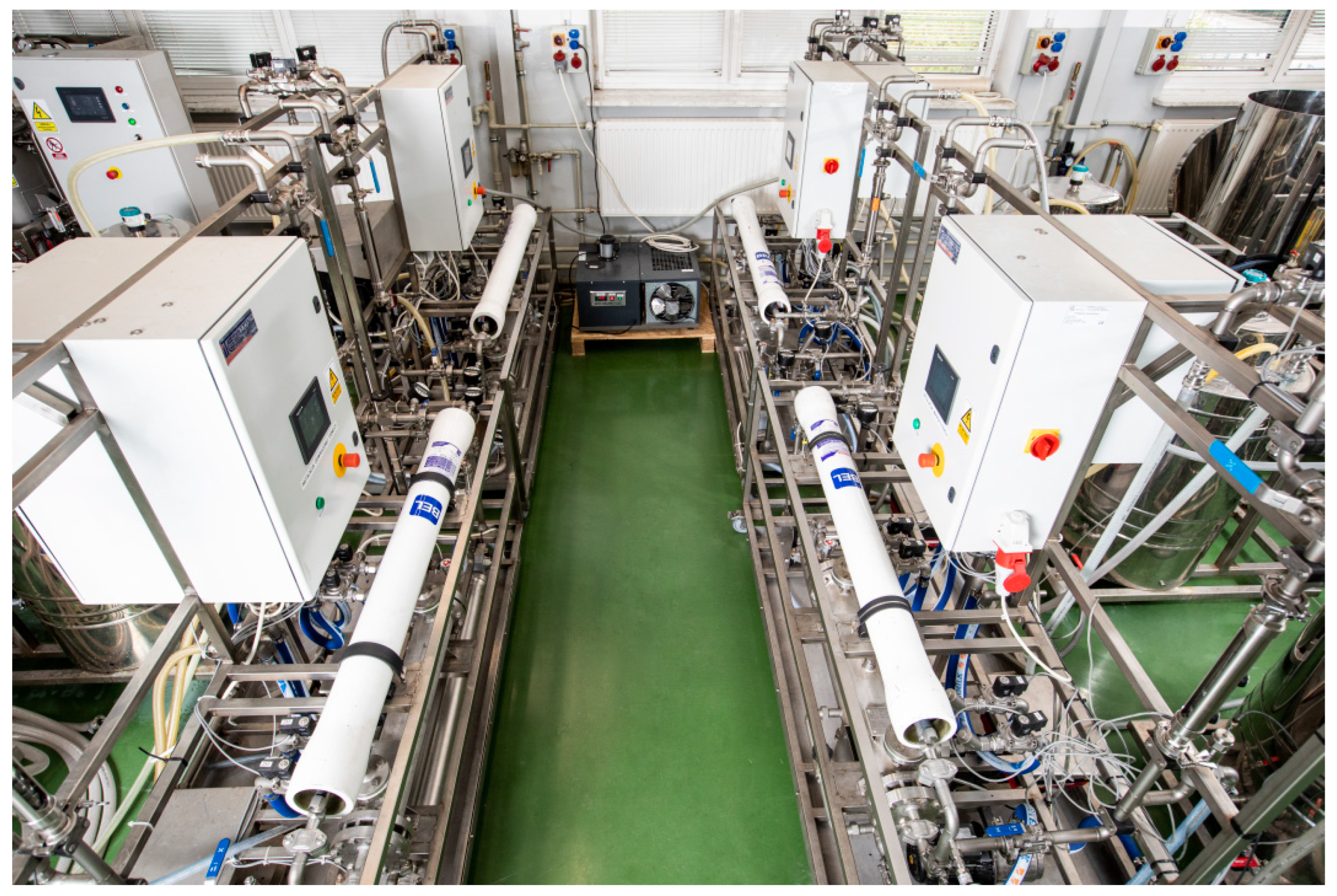
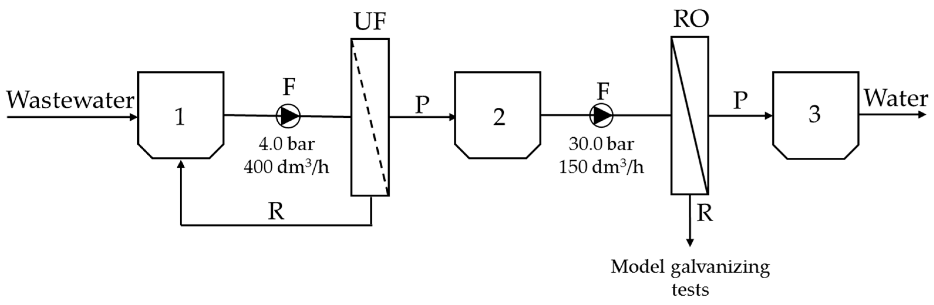
2.2. Membrane Filtration
2.3. Mode-Galvanizing Tests
3. Results and Discussion
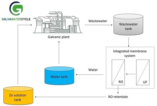
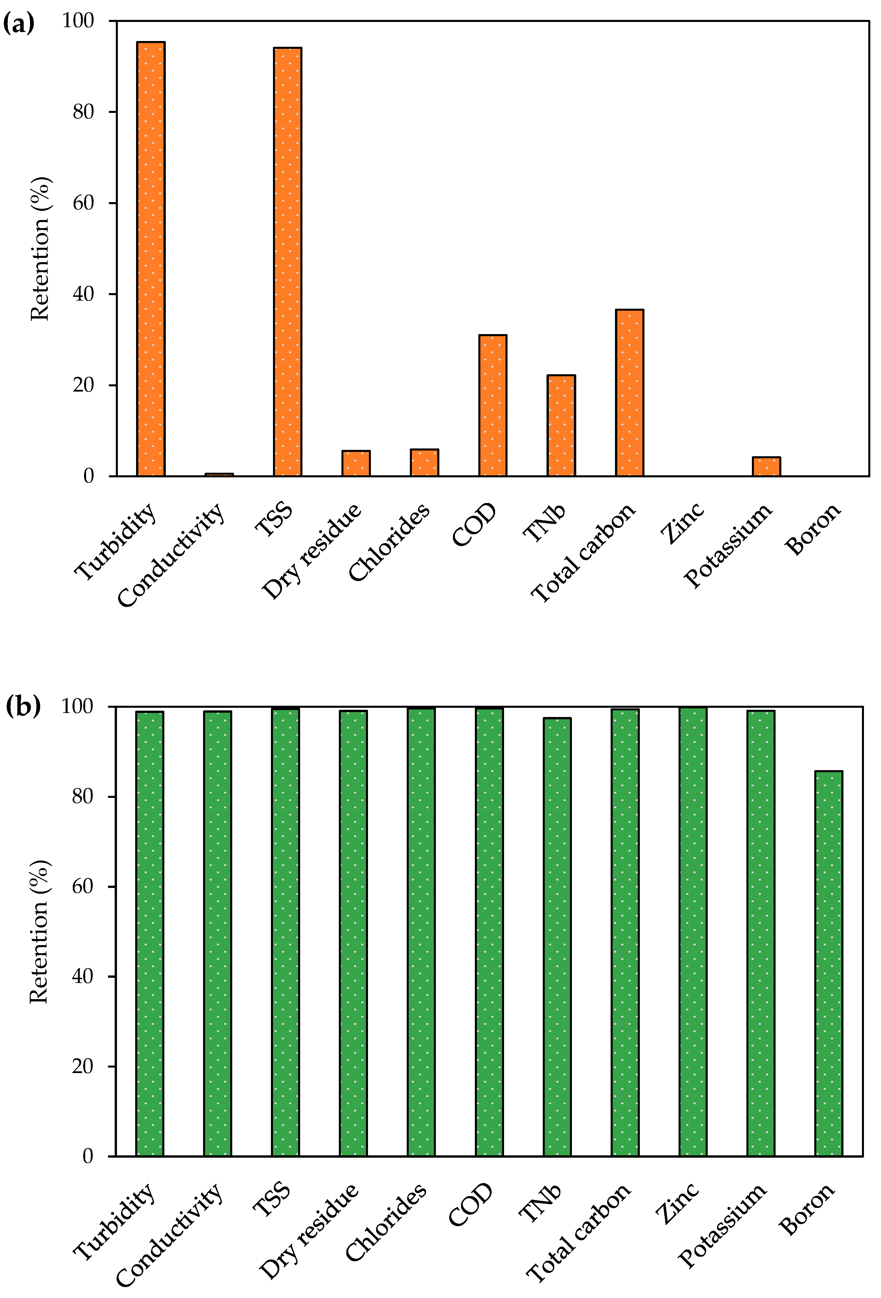
3.1. Galvanic Wastewater Treatment in the UF/RO System
3.2. Tests Verifying the Possibility to Use Retentate after RO
4. Conclusions
Author Contributions
Funding
Institutional Review Board Statement
Data Availability Statement
Acknowledgments
Conflicts of Interest
References
- Rajoria, S.; Vashishtha, M.; Sangal, V.K. Treatment of electroplating industry wastewater: A review on the various techniques. Environ. Sci. Pollut. Res. 2022, 29, 72196–72246. [Google Scholar] [CrossRef] [PubMed]
- Velazquez-Peña, S.; Barrera-Díaz, C.; Linares-Hernández, I.; Bilyeu, B.; Martínez-Delgadillo, S.A. An effective electrochemical Cr(VI) removal contained in electroplating industry wastewater and the chemical characterization of the sludge produced. Ind. Eng. Chem. Res. 2012, 51, 5905–5910. [Google Scholar] [CrossRef]
- Yaqoob, A.A.; Guerrero–Barajas, C.; Ahmad, A.; Ibrahim, M.N.M.; Alshammari, M.B. Advanced Technologies for Wastewater Treatment. In Green Chemistry for Sustainable Water Purification; John Wiley & Sons, Inc.: New York, NY, USA, 2023; pp. 179–202. [Google Scholar]
- Zelinski, R.; Silvestre, W.P.; Duarte, J.; Livinalli, N.F.; Zeni, M.; Baldasso, C. Evaluation of the use of reverse osmosis in the treatment of galvanic effluents. J. Membr. Sci. Res. 2023, 9, 562616. [Google Scholar]
- Chavez Porras, Á.; Cristancho Montenegro, D.L.; Ospina Granados, É.A. A clean alternative for galvanic wastewater treatment: Literature review. Rev. Ing. Univ. Medellin 2009, 8, 39–50. [Google Scholar]
- Arroub, H.; Hsissou, R.; Elharfi, A. Investigation of modified chitosan as potential polyelectrolyte polymer and eco-friendly for the treatment of galvanization wastewater using novel hybrid process. Results Chem. 2020, 2, 100047. [Google Scholar] [CrossRef]
- Zueva, S.B.; Ferella, F.; Innocenzi, V.; De Michelis, I.; Corradini, V.; Ippolito, N.M.; Vegliò, F. Recovery of zinc from treatment of spent acid solutions from the pickling stage of galvanizing plants. Sustainability 2021, 13, 407. [Google Scholar] [CrossRef]
- Stala, Ł.; Ulatowska, J.; Polowczyk, I. Copper(II) ions removal from model galvanic wastewater by green one-pot synthesised amino-hypophosphite polyampholyte. J. Hazard. Mater. 2022, 436, 129047. [Google Scholar] [CrossRef]
- Yeh, M.S.; Ou, H.H.; Su, Y.C.; Lin, P.H. Design and parameter optimization of a full-scale wastewater reclamation plant including pretreatment, electrodialysis reversal, and ion exchange in steel manufacturing processes. J. Environ. Eng. 2016, 142, 05016003. [Google Scholar] [CrossRef]
- Makisha, N.; Yunchina, M. Methods and solutions for galvanic waste water treatment. MATEC Web Conf. 2017, 106, 07016. [Google Scholar] [CrossRef]
- Sharma, D.; Chaudhari, P.K.; Dubey, S.; Prajapati, A.K. Electrocoagulation treatment of electroplating wastewater: A Review. J. Environ. Eng. 2022, 146, 03120009. [Google Scholar] [CrossRef]
- Abdel-Shafy, H.I.; Rehan, M.M.M.; Mahmoud, A.I.H.; Taha, M.A.R.; Maamoun, M.A. Hamid Treatment of industrial electroplating wastewater for metals removal via electrocoagulation continous flow reactors. Water Pract. Technol. 2022, 17, 555–566. [Google Scholar] [CrossRef]
- Pervov, A.G.; Adrianov, A.P.; Gorbunova, T.P.; Bagdasaryan, A.S. Membrane technologies in the solution of environmental problems. Pet. Chem. 2015, 55, 879–886. [Google Scholar] [CrossRef]
- Hegoburu, I.; Zedda, K.L.; Velizarov, S. Treatment of electroplating wastewater using NF pH-stable membranes: Characterization and application. Membranes 2020, 10, 399. [Google Scholar] [CrossRef]
- Kumar, J.; Joshi, H.; Malyan, S.K. Removal of copper, nickel, and zinc ions from an aqueous solution through electrochemical and nanofiltration membrane processes. Appl. Sci. 2022, 12, 280. [Google Scholar] [CrossRef]
- Best Available Techniques (BAT) Guidelines for the Surface Treatment of Metals and Plastics; Institute of Precision Mechanics: Warsaw, Poland, 2009.
- Brinkmann, T.; Santonja, G.G.; Yükseler, H.; Roudier, S.; Sancho, L.D. Best Available Techniques (BAT) Reference Document for Common Waste Water and Waste Gas Treatment/Management Systems in the Chemical Sector. Publ. Off. Eur. Union 2016, 3. [Google Scholar]
- Şahin Taş, D. Removal of Zinc from an Aqueous Solution Using Micellar-Enhanced Ultrafiltration (MEUF) with Surfactants. J. Turk. Chem. Soc. A Chem. 2018, 5, 691–700. [Google Scholar] [CrossRef]
- Lam, B.; Déon, S.; Morin-Crini, N.; Crini, G.; Fievet, P. Polymer-enhanced ultrafiltration for heavy metal removal: Influence of chitosan and carboxymethyl cellulose on filtration performances. J. Clean. Prod. 2018, 171, 927–933. [Google Scholar] [CrossRef]
- Siddique, A.; Yaqoob, A.A.; Mirza, M.A.; Kanwal, A.; Ibrahim, M.N.M.; Ahmad, A. Chapter 14—Potential use of ultrafiltration (UF) membrane for remediation of metal contaminants. In Emerging Techniques for Treatment of Toxic Metals from Wastewater; Ahmad, A., Jawaid, M., Eds.; Elsevier: Amsterdam, The Netherlands, 2023; pp. 341–364. [Google Scholar]
- Innocenzi, V.; Cantarini, F.; Amato, A.; Morico, B.; Ippolito, N.M.; Beolchini, F.; Prisciandaro, M.; Vegliò, F. Case study on technical feasibility of galvanic wastewater treatment plant based on life cycle assessment and costing approach. J. Environ. Chem. Eng. 2020, 8, 104535. [Google Scholar] [CrossRef]
- Yaqoob, A.A.; Kanwal, A.; Ibrahim, M.N.M.; Ahmad, A. Chapter 15—Application and fabrication of nanofiltration membrane for separation of metal ions from wastewater. In Emerging Techniques for Treatment of Toxic Metals from Wastewater; Ahmad, A., Jawaid, M., Eds.; Elsevier: Amsterdam, The Netherlands, 2023; pp. 365–398. [Google Scholar]
- Qasem, N.A.A.; Mohammed, R.H.; Lawal, D.U. Removal of heavy metal ions from wastewater: A comprehensive and critical review. Clean Water 2021, 4, 36. [Google Scholar] [CrossRef]
- Kowalik-Klimczak, A.; Zalewski, M.; Gierycz, P. Removal of Cr(III) ions from salt solution by nanofiltration: Experimental and modelling analysis. Pol. J. Chem. Technol. 2016, 18, 10–16. [Google Scholar] [CrossRef] [Green Version]
- Petrinic, I.; Korenak, J.; Povodnik, D.; Hélix-Nielsen, C. A feasibility study of ultrafiltration/reverse osmosis (UF/RO)-based wastewater treatment and reuse in the metal finishing industry. J. Clean. Prod. 2015, 101, 292–300. [Google Scholar] [CrossRef]
- Gadelmawla, E.S.; Koura, M.M.; Maksoud, T.M.A.; Elewa, I.M.; Soliman, H.H. Roughness parameters. J. Mater. Process. Technol. 2002, 123, 133–145. [Google Scholar] [CrossRef]
- Qin, J.J.; Wai, M.N.; Oo, M.H.; Wong, F.S. A feasibility study on the treatment and recycling of a wastewater from metal plating. J. Membr. Sci. 2002, 208, 213–221. [Google Scholar] [CrossRef]
- Osuchowska, E.; Buczko, Z. Electrolytic zinc coatings and current conditions of the deposition process. Surf. Eng. 2019, 24, 26–33. [Google Scholar] [CrossRef]
- Osuchowska, E.; Buczko, Z. Zn/C composite coatings with carbon dispersion produced by electrochemical method. Surf. Eng. 2018, 23, 3–10. [Google Scholar]


| Type of Membrane | UF UP150 | RO TM710 |
|---|---|---|
| Manufacturer | Microdyn Nadir | Toray |
| Material | PES | PA |
| Area (m2) | 6.0 | 8.1 |
| NaCl retention (%) | - | 99.7 |
| Cut-off (Da) | 150,000 | - |
| pH range | 0–14 | 2–11 |
| Max. temperature (°C) | 95 | 45 |
| Parameter | Value |
|---|---|
| pH | 4.121 ± 0.004 |
| Turbidity (FNU) | 420.3 ± 1.5 |
| Conductivity (mS/cm) | 35.919 ± 0.036 |
| Total suspended solids (mg/dm3) | 431.3 ± 7.2 |
| Dry residue (%) | 3.289 ± 0.011 |
| Chlorides (g/dm3) | 11.042 ± 0.018 |
| Chemical oxygen demand (g O2/dm3) | 15.95 ± 0.21 |
| Total nitrogen bound (mg/dm3) | 65.8 ± 3.7 |
| Total carbon (g/dm3) | 4.256 ± 0.072 |
| Zinc (g/dm3) | 2.802 ± 0.013 |
| Potassium (g/dm3) | 9.560 ± 0.010 |
| Boron (mg/dm3) | 235.1 ± 1.6 |
| Parameter | Permeate | Retentate |
|---|---|---|
| pH | 5.145 ± 0.003 | 4.146 ± 0.005 |
| Turbidity (FNU) | 2.507 ± 0.093 | 217.7 ± 2.1 |
| Conductivity (mS/cm) | 0.6421 ± 0.0018 | 58.71 ± 0.20 |
| Total suspended solids (mg/dm3) | 0.983 ± 0.029 | 192.7 ± 1.5 |
| Dry residue (%) | 0.052 ± 0.002 | 5.541 ± 0.039 |
| Chlorides (g/dm3) | 0.0759 ± 0.0015 | 19.750 ± 0.370 |
| Chemical oxygen demand (mg O2/dm3) | <LOD | 24,927 ± 76 |
| Total nitrogen bound (mg/dm3) | 2.552 ± 0.069 | 99.9 ± 2.1 |
| Total carbon (g/dm3) | 0.03694 ± 0.00047 | 6.050 ± 270 |
| Zinc (g/dm3) | 0.00650 ± 0.00010 | 4.800 ± 0.010 |
| Potassium (g/dm3) | 0.160 ± 0.005 | 17.10 ± 0.17 |
| Boron (mg/dm3) | 51.20 ± 0.72 | 357.0 ± 4.3 |
| Conditions of Deposition | Bath Composition | Appearance of the Deposited Coating |
|---|---|---|
| I = 1.0 A current density 0.1–5.0 A/dm2 | ZnCl2 KCl H3BO3 |  dark and matt |
| ZnCl2 KCl H3BO3 gloss carrier |  dark and matt | |
| ZnCl2 KCl H3BO3 gloss carrier gloss additive |  bright and glossy |
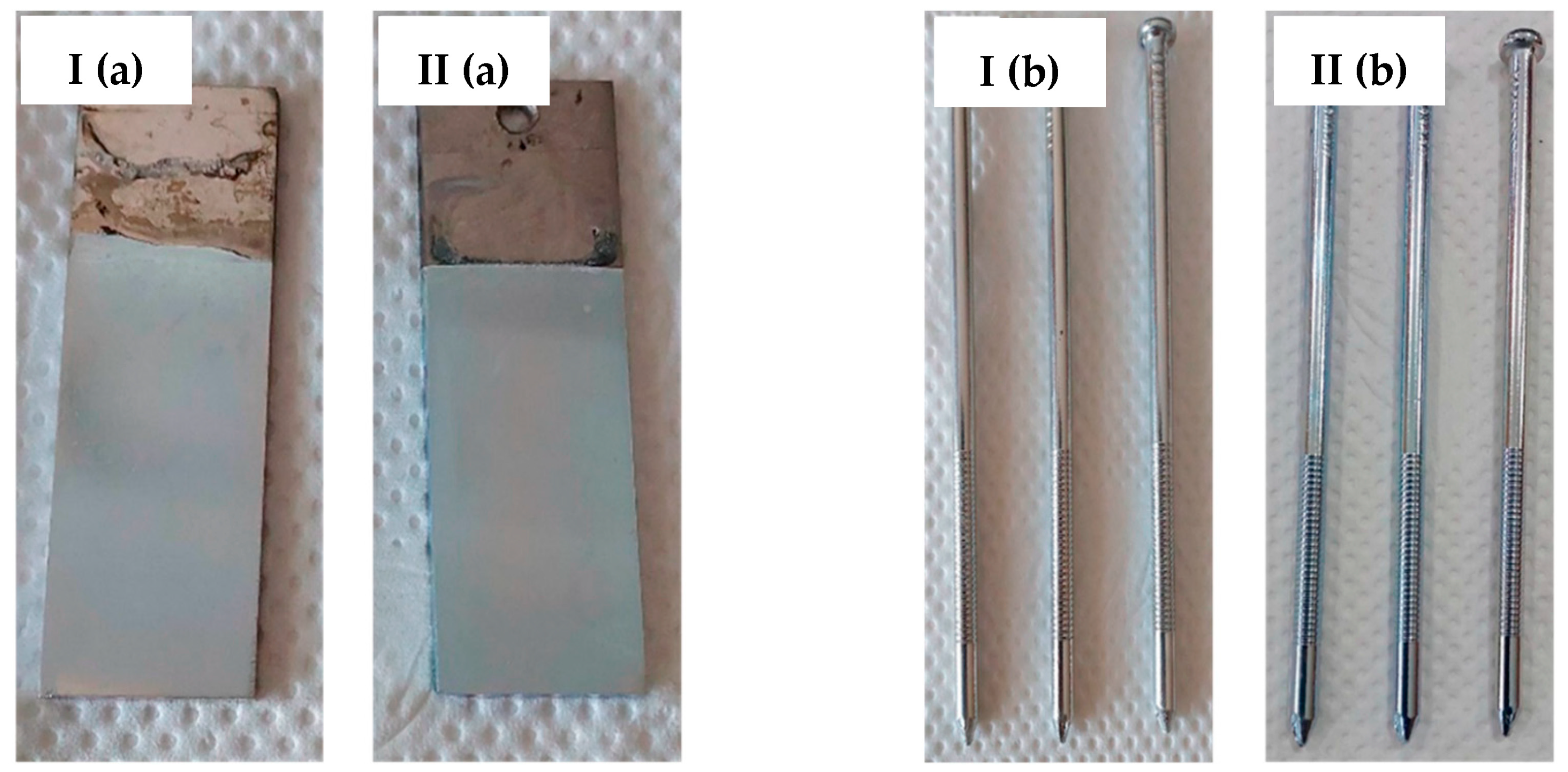
| Sample | Thickness (μm) | |
|---|---|---|
| Samples from the RO Retentate-Based Bath | Samples from the Tap Water-Based Bath | |
| Flat substrate | 16.9 ± 0.8 | 17.2 ± 0.6 |
| Industrial detail No. 1 | 16.5 ± 0.8 | 14.5 ± 1.8 |
| Industrial detail No. 2 | 17.1 ± 0.6 | 17.3 ± 1.8 |
| Industrial detail No. 3 | 16.9 ± 1.0 | 16.5 ± 0.9 |
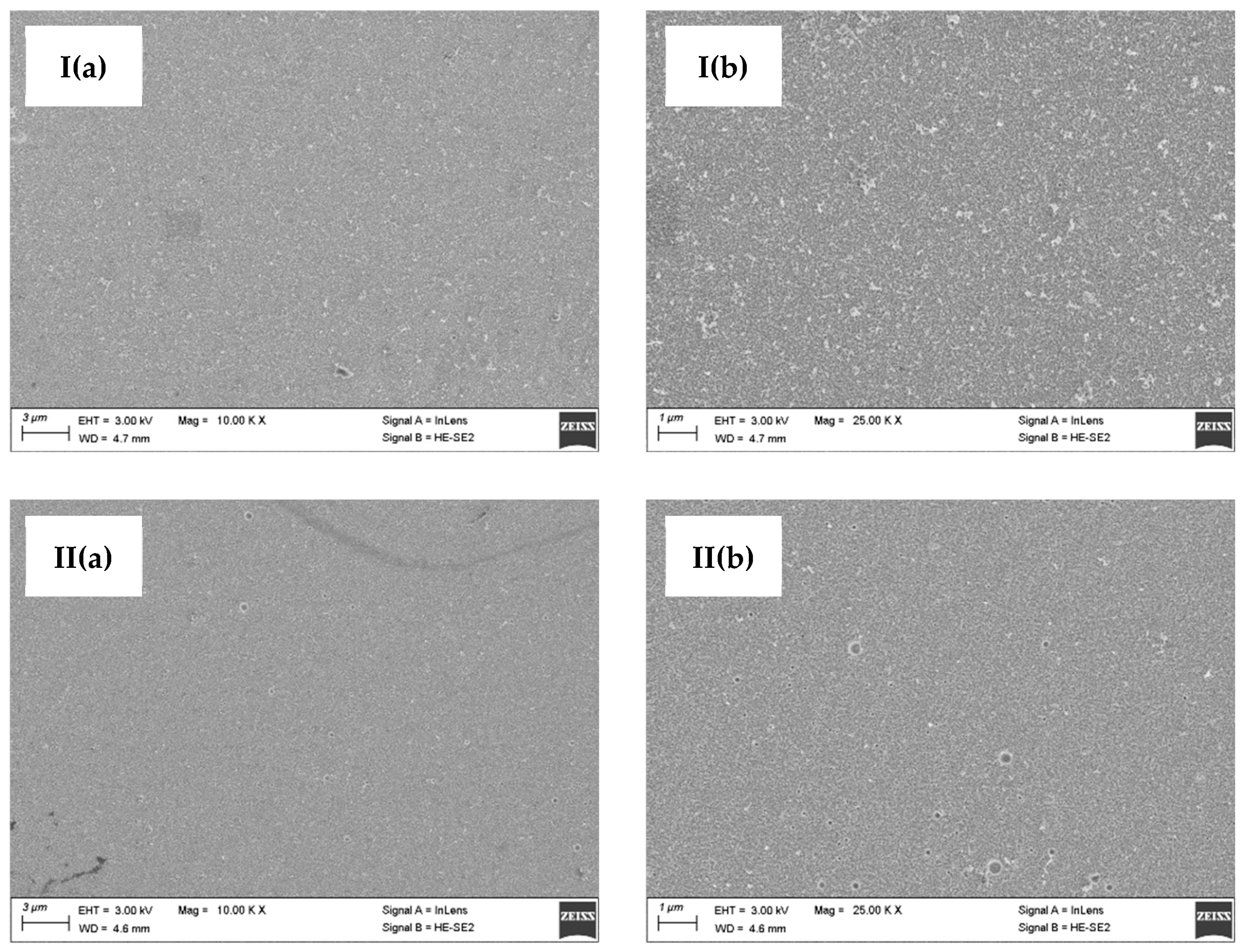
| Type of Coating | Roughness (μm) | |
|---|---|---|
| Ra | Rz | |
| Coating deposited in the RO retentate-based bath | 0.023 ± 0.007 | 0.186 ± 0.042 |
| Coating deposited in the tap water-based bath | 0.016 ± 0.001 | 0.124 ± 0.018 |
| Type of Coating | Microhardness (HV 0.025) |
|---|---|
| Coating deposited in the RO retentate-based bath | 127 ± 3 |
| Coating deposited in the tap water-based bath | 125 ± 3 |
Disclaimer/Publisher’s Note: The statements, opinions and data contained in all publications are solely those of the individual author(s) and contributor(s) and not of MDPI and/or the editor(s). MDPI and/or the editor(s) disclaim responsibility for any injury to people or property resulting from any ideas, methods, instructions or products referred to in the content. |
© 2023 by the authors. Licensee MDPI, Basel, Switzerland. This article is an open access article distributed under the terms and conditions of the Creative Commons Attribution (CC BY) license (https://creativecommons.org/licenses/by/4.0/).
Share and Cite
Kowalik-Klimczak, A.; Gajewska-Midziałek, A.; Buczko, Z.; Łożyńska, M.; Życki, M.; Barszcz, W.; Ciciszwili, T.; Dąbrowski, A.; Kasierot, S.; Charasińska, J.; et al. Circular Economy Approach in Treatment of Galvanic Wastewater Employing Membrane Processes. Membranes 2023, 13, 325. https://doi.org/10.3390/membranes13030325
Kowalik-Klimczak A, Gajewska-Midziałek A, Buczko Z, Łożyńska M, Życki M, Barszcz W, Ciciszwili T, Dąbrowski A, Kasierot S, Charasińska J, et al. Circular Economy Approach in Treatment of Galvanic Wastewater Employing Membrane Processes. Membranes. 2023; 13(3):325. https://doi.org/10.3390/membranes13030325
Chicago/Turabian StyleKowalik-Klimczak, Anna, Anna Gajewska-Midziałek, Zofia Buczko, Monika Łożyńska, Maciej Życki, Wioletta Barszcz, Tinatin Ciciszwili, Adrian Dąbrowski, Sonia Kasierot, Jadwiga Charasińska, and et al. 2023. "Circular Economy Approach in Treatment of Galvanic Wastewater Employing Membrane Processes" Membranes 13, no. 3: 325. https://doi.org/10.3390/membranes13030325