

An Economical Composite Membrane with High Ion Selectivity for Vanadium Flow Batteries
 and
and 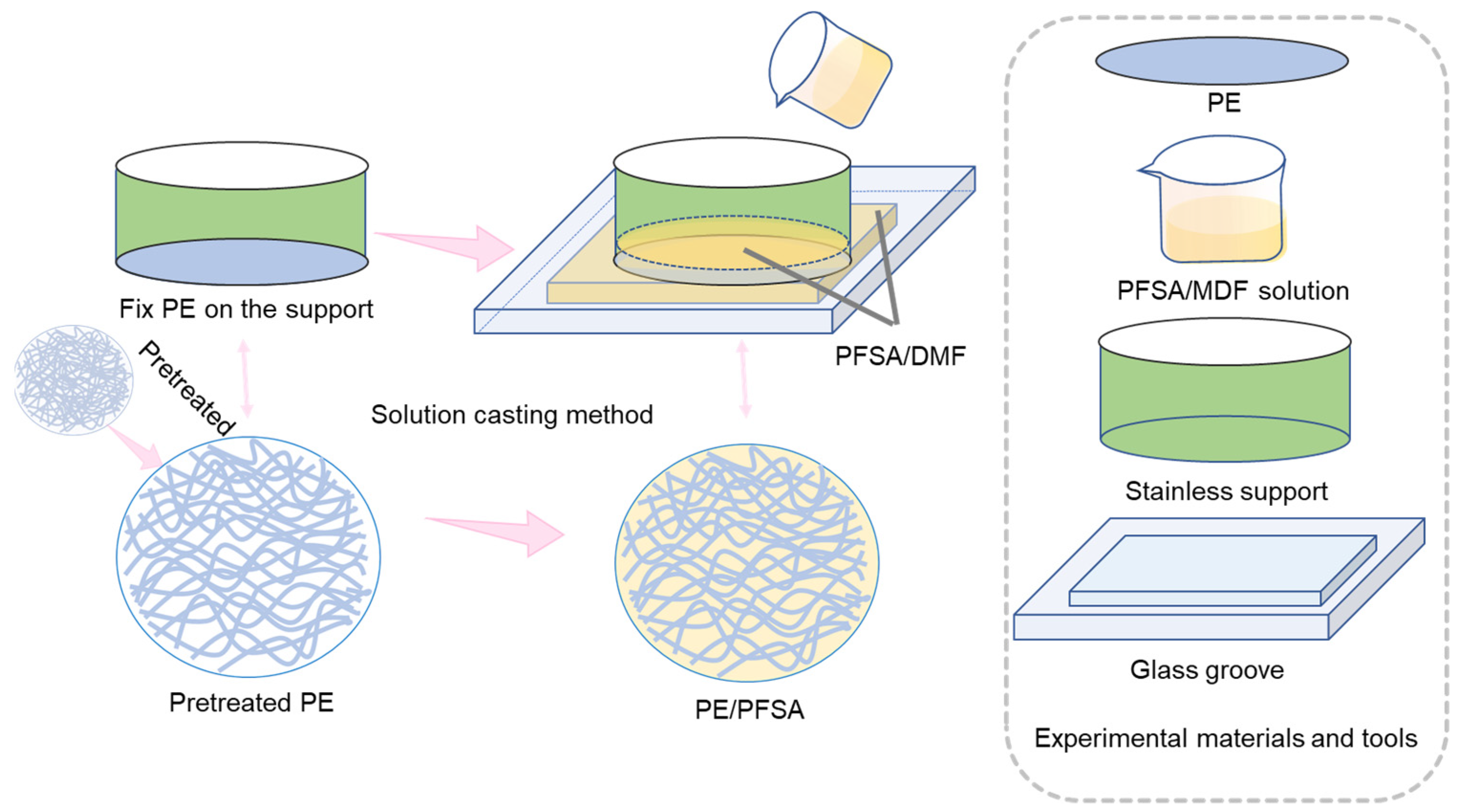
Abstract
:1. Introduction
2. Experimental Section
2.1. Materials
2.2. Preparation of the PE/PFSA Composite Membrane
2.3. Characterization Methods
2.4. VFB Single-Cell Performance
3. Results and Discussion
4. Summary
Supplementary Materials
Author Contributions
Funding
Informed Consent Statement
Data Availability Statement
Conflicts of Interest
References
- Yang, Z.; Zhang, J.; Kintner-Meyer, M.C.; Lu, X.; Choi, D.; Lemmon, J.P.; Liu, J. Electrochemical energy storage for green grid. Chem. Rev. 2011, 111, 3577–3613. [Google Scholar] [CrossRef] [PubMed]
- Ke, X.; Prahl, J.M.; Alexander, J.I.D.; Wainright, J.S.; Zawodzinski, T.A.; Savinell, R.F. Rechargeable redox flow batteries: Flow fields, stacks and design considerations. Chem. Soc. Rev. 2018, 47, 8721–8743. [Google Scholar] [CrossRef] [PubMed]
- Poullikkas, A. A comparative overview of large-scale battery systems for electricity storage. Renew. Sustain. Energy Rev. 2013, 27, 778–788. [Google Scholar] [CrossRef]
- Janoschka, T.; Martin, N.; Martin, U.; Friebe, C.; Morgenstern, S.; Hiller, H.; Hager, M.D.; Schubert, U.S. An aqueous, polymer-based redox-flow battery using non-corrosive, safe, and low-cost materials. Nature 2015, 527, 78–81. [Google Scholar] [CrossRef] [PubMed]
- Yuan, Z.; Duan, Y.; Zhang, H.; Li, X.; Zhang, H.; Vankelecom, I. Advanced porous membranes with ultra-high selectivity and stability for vanadium flow batteries. Energy Environ. Sci. 2016, 9, 441–447. [Google Scholar] [CrossRef]
- Jiang, B.; Wu, L.; Yu, L.; Qiu, X.; Xi, J. A comparative study of Nafion series membranes for vanadium redox flow batteries. J. Membr. Sci. 2016, 510, 18–26. [Google Scholar] [CrossRef]
- Ye, J.; Yuan, D.; Ding, M.; Long, Y.; Long, T.; Sun, L.; Jia, C. A cost-effective nafion/lignin composite membrane with low vanadium ion permeation for high performance vanadium redox flow battery. J. Power Sources 2021, 482, 229023. [Google Scholar] [CrossRef]
- Reed, D.; Thomsen, E.; Wang, W.; Nie, Z.; Li, B.; Wei, X.; Koeppel, B.; Sprenkle, V. Performance of Nafion® N115, Nafion® NR-212, and Nafion® NR-211 in a 1 kW class all vanadium mixed acid redox flow battery. J. Power Sources 2015, 285, 425–430. [Google Scholar] [CrossRef] [Green Version]
- Minke, C.; Turek, T. Economics of vanadium redox flow battery membranes. J. Power Sources 2015, 286, 247–257. [Google Scholar] [CrossRef]
- Li, J.; Yuan, X.; Liu, S.; He, Z.; Zhou, Z.; Li, A. A Low-Cost and High-Performance Sulfonated Polyimide Proton-Conductive Membrane for Vanadium Redox Flow/Static Batteries. ACS Appl. Mater. Interfaces 2017, 9, 32643–32651. [Google Scholar] [CrossRef]
- Schmidt-Rohr, K.; Chen, Q. Parallel cylindrical water nanochannels in Nafion fuel-cell membranes. Nat. Mater. 2008, 7, 75–83. [Google Scholar] [CrossRef]
- Zhou, X.L.; Zhao, T.S.; An, L.; Wei, L.; Zhang, C. The use of polybenzimidazole membranes in vanadium redox flow batteries leading to increased coulombic efficiency and cycling performance. Electrochim. Acta 2015, 153, 492–498. [Google Scholar] [CrossRef]
- Noh, C.; Jung, M.; Henkensmeier, D.; Nam, S.W.; Kwon, Y. Vanadium Redox Flow Batteries Using meta-Polybenzimidazole-Based Membranes of Different Thicknesses. ACS Appl. Mater. Interfaces 2017, 9, 36799–36809. [Google Scholar] [CrossRef]
- Chen, D.; Hickner, M.A.; Agar, E.; Kumbur, E.C. Optimizing membrane thickness for vanadium redox flow batteries. J. Membr. Sci. 2013, 437, 108–113. [Google Scholar] [CrossRef]
- Lin, C.-H.; Yang, M.-C.; Wei, H.-J. Amino-silica modified Nafion membrane for vanadium redox flow battery. J. Power Sources 2015, 282, 562–571. [Google Scholar] [CrossRef]
- Lou, X.; Yuan, D.; Yu, Y.; Lei, Y.; Ding, M.; Sun, Q.; Jia, C. A Cost-effective Nafion Composite Membrane as an Effective Vanadium-Ion Barrier for Vanadium Redox Flow Batteries. Asian Chem. Ed. Scoiety 2020, 15, 2357–2363. [Google Scholar] [CrossRef]
- Wu, C.; Lu, S.; Zhang, J.; Xiang, Y. Inducing microstructural changes in Nafion by incorporating graphitic carbon nitride to enhance the vanadium-blocking effect. Phys. Chem. Chem. Phys. 2018, 20, 7694–7700. [Google Scholar] [CrossRef]
- Luo, Q.; Zhang, H.; Chen, J.; Qian, P.; Zhai, Y. Modification of Nafion membrane using interfacial polymerization for vanadium redox flow battery applications. J. Membr. Sci. 2008, 311, 98–103. [Google Scholar] [CrossRef]
- Lu, S.; Wu, C.; Liang, D.; Tan, Q.; Xiang, Y. Layer-by-layer self-assembly of Nafion–[CS–PWA] composite membranes with suppressed vanadium ion crossover for vanadium redox flow battery applications. RSC Adv. 2014, 4, 24831–24837. [Google Scholar] [CrossRef]
- An, H.; Zhang, R.; Li, W.; Li, P.; Qian, H.; Yang, H. Surface-Modified Approach to Fabricate Nafion Membranes Covalently Bonded with Polyhedral Oligosilsesquioxane for Vanadium Redox Flow Batteries. ACS Appl. Mater. Interfaces 2022, 14, 7845–7855. [Google Scholar] [CrossRef]
- Jiang, B.; Yu, L.; Wu, L.; Mu, D.; Liu, L.; Xi, J.; Qiu, X. Insights into the Impact of the Nafion Membrane Pretreatment Process on Vanadium Flow Battery Performance. ACS Appl. Mater. Interfaces 2016, 8, 12228–12238. [Google Scholar] [CrossRef] [PubMed]
- Jeong, S.; Kim, L.-H.; Kwon, Y.; Kim, S. Effect of nafion membrane thickness on performance of vanadium redox flow battery. Korean J. Chem. Eng. 2014, 31, 2081–2087. [Google Scholar] [CrossRef]
- Li, X.; Zhang, H.; Mai, Z.; Zhang, H.; Vankelecom, I. Ion exchange membranes for vanadium redox flow battery (VRB) applications. Energy Environ. Sci. 2011, 4, 1147–1160. [Google Scholar] [CrossRef]
- Abdiani, M.; Abouzari-Lotf, E.; Ting, T.M.; Nia, P.M.; Sha’rani, S.S.; Shockravi, A.; Ahmad, A. Novel polyolefin based alkaline polymer electrolyte membrane for vanadium redox flow batteries. J. Power Sources 2019, 424, 245–253. [Google Scholar] [CrossRef]
- Thong, P.T.; Ajeya, K.V.; Dhanabalan, K.; Roh, S.H.; Son, W.K.; Park, S.C.; Jung, H.Y. A coupled-layer ion-conducting membrane using composite ionomer and porous substrate for application to vanadium redox flow battery. J. Power Sources 2022, 521, 230912. [Google Scholar] [CrossRef]
- Teng, X.; Dai, J.; Su, J.; Zhu, Y.; Liu, H.; Song, Z. A high performance polytetrafluoroethene/Nafion composite membrane for vanadium redox flow battery application. J. Power Sources 2013, 240, 131–139. [Google Scholar] [CrossRef]
- Jia, C.; Liu, J.; Yan, C. A multilayered membrane for vanadium redox flow battery. J. Power Sources 2012, 203, 190–194. [Google Scholar] [CrossRef]
- Mai, Z.; Zhang, H.; Li, X.; Xiao, S.; Zhang, H. Nafion/polyvinylidene fluoride blend membranes with improved ion selectivity for vanadium redox flow battery application. J. Power Sources 2011, 196, 5737–5741. [Google Scholar] [CrossRef]
- Zhou, X.L.; Zhao, T.S.; An, L.; Zeng, Y.K.; Zhu, X.B. Performance of a vanadium redox flow battery with a VANADion membrane. Appl. Energy 2016, 180, 353–359. [Google Scholar] [CrossRef]
- Ren, X.; Zhao, L.; Che, X.; Cai, Y.; Li, Y.; Li, H.; Chen, H.; He, H.; Liu, J.; Yang, J. Quaternary ammonium groups grafted polybenzimidazole membranes for vanadium redox flow battery applications. J. Power Sources 2020, 457, 228037. [Google Scholar] [CrossRef]
- Zhu, X.; Jiang, X.; Ai, X.; Yang, H.; Cao, Y. A Highly Thermostable Ceramic-Grafted Microporous Polyethylene Separator for Safer Lithium-Ion Batteries. ACS Appl. Mater. Interfaces 2015, 7, 24119–24126. [Google Scholar] [CrossRef]
- Liang, Z.X.; Chen, W.M.; Liu, J.G.; Wang, S.L.; Zhou, Z.H.; Li, W.Z.; Sun, G.Q.; Xin, Q. FT-IR study of the microstructure of Nafion((R)) membrane. J. Membr. Sci. 2004, 233, 39–44. [Google Scholar] [CrossRef]
- Hwang, S.; Lee, D.; Rho, Y.; Yoon, K.S.; Yu, D.M.; Yoon, S.J.; Kim, S.; Hong, Y.T.; So, S. Planar orientation of hydrophilic channels by biaxial deformation of perfluorinated sulfonic acid membranes for vanadium redox flow batteries. J. Power Sources 2021, 489, 229497. [Google Scholar] [CrossRef]
- Xi, J.; Wu, Z.; Teng, X.; Zhao, Y.; Chen, L.; Qiu, X. Self-assembled polyelectrolyte multilayer modified Nafion membrane with suppressed vanadium ion crossover for vanadium redox flow batteries. J. Mater. Chem. 2008, 18, 1232–1238. [Google Scholar] [CrossRef]
- Teng, X.; Dai, J.; Bi, F.; Yin, G. Ultra-thin polytetrafluoroethene/Nafion/silica composite membrane with high performance for vanadium redox flow battery. J. Power Sources 2014, 272, 113–120. [Google Scholar] [CrossRef]
- Yang, M.-C.; Lin, C.-H.; Kuo, J.-T.; Wei, H.-J. Effect of grafting of poly(styrenesulfonate) onto Nafion membrane on the performance of vanadium redox flow battery. J. Electroanal. Chem. 2017, 807, 88–96. [Google Scholar] [CrossRef]
- Ahn, S.M.; Jeong, H.Y.; Jang, J.-K.; Lee, J.Y.; So, S.; Kim, Y.J.; Hong, Y.T.; Kim, T.-H. Polybenzimidazole/Nafion hybrid membrane with improved chemical stability for vanadium redox flow battery application. Rsc Adv. 2018, 8, 25304–25312. [Google Scholar] [CrossRef] [Green Version]
- Sun, C.; Negro, E.; Nale, A.; Pagot, G.; Vezzu, K.; Zawodzinski, T.A.; Meda, L.; Gambaro, C.; di Noto, V. An efficient barrier toward vanadium crossover in redox flow batteries: The bilayer Nafion/(WO3)(x) hybrid inorganic-organic membrane. Electrochim. Acta 2021, 378, 138133. [Google Scholar] [CrossRef]
- Wang, F.; Zhang, Z.; Jiang, F. Dual-porous structured membrane for ion-selection in vanadium flow battery. J. Power Sources 2021, 506, 230234. [Google Scholar] [CrossRef]
- Luo, Q.; Zhang, H.; Chen, J.; You, D.; Sun, C.; Zhang, Y. Preparation and characterization of Nafion/SPEEK layered composite membrane and its application in vanadium redox flow battery. J. Membr. Sci. 2008, 325, 553–558. [Google Scholar] [CrossRef]
- Palanisamy, G.; Sadhasivam, T.; Park, W.-S.; Bae, S.T.; Roh, S.-H.; Jung, H.-Y. Tuning the Ion Selectivity and Chemical Stability of a Biocellulose Membrane by PFSA lonomer Reinforcement for Vanadium Redox Flow Battery Applications. ACS Sustain. Chem. Eng. 2020, 8, 2040–2051. [Google Scholar] [CrossRef]
- Kim, J.; Jeon, J.-D.; Kwak, S.-Y. Nafion-based composite membrane with a permselective layered silicate layer for vanadium redox flow battery. Electrochem. Commun. 2014, 38, 68–70. [Google Scholar] [CrossRef]
- Teng, X.; Zhao, Y.; Xi, J.; Wu, Z.; Qiu, X.; Chen, L. Nafion/organic silica modified TiO2 composite membrane for vanadium redox flow battery via in situ sol-gel reactions. J. Membr. Sci. 2009, 341, 149–154. [Google Scholar] [CrossRef]
- Teng, X.; Zhao, Y.; Xi, J.; Wu, Z.; Qiu, X.; Chen, L. Nafion/organically modified silicate hybrids membrane for vanadium redox flow battery. J. Power Sources 2009, 189, 1240–1246. [Google Scholar] [CrossRef]


Disclaimer/Publisher’s Note: The statements, opinions and data contained in all publications are solely those of the individual author(s) and contributor(s) and not of MDPI and/or the editor(s). MDPI and/or the editor(s) disclaim responsibility for any injury to people or property resulting from any ideas, methods, instructions or products referred to in the content. |
© 2023 by the authors. Licensee MDPI, Basel, Switzerland. This article is an open access article distributed under the terms and conditions of the Creative Commons Attribution (CC BY) license (https://creativecommons.org/licenses/by/4.0/).
Share and Cite
Zhang, Y.; Zhang, D.; Luan, C.; Zhang, Y.; Yu, W.; Liu, J.; Yan, C. An Economical Composite Membrane with High Ion Selectivity for Vanadium Flow Batteries. Membranes 2023, 13, 272. https://doi.org/10.3390/membranes13030272
Zhang Y, Zhang D, Luan C, Zhang Y, Yu W, Liu J, Yan C. An Economical Composite Membrane with High Ion Selectivity for Vanadium Flow Batteries. Membranes. 2023; 13(3):272. https://doi.org/10.3390/membranes13030272
Chicago/Turabian StyleZhang, Yue, Denghua Zhang, Chao Luan, Yifan Zhang, Wenjie Yu, Jianguo Liu, and Chuanwei Yan. 2023. "An Economical Composite Membrane with High Ion Selectivity for Vanadium Flow Batteries" Membranes 13, no. 3: 272. https://doi.org/10.3390/membranes13030272