Review

Decarbonization of Power and Industrial Sectors: The Role of Membrane Processes

1
Department of IT, Automation, and Control, Tashkent Chemical-Technological Institute, Tashkent 100011, Uzbekistan
2
Department of Chemical and Biomolecular Engineering, University of Cantabria, 39005 Santander, Spain
3
Department of Engineering Technologies, Shahrisabz Branch of Tashkent Chemical-Technological Institute, Shahrisabz 181306, Uzbekistan
*
Author to whom correspondence should be addressed.
These authors contributed equally to this work.
Membranes 2023, 13(2), 130; https://doi.org/10.3390/membranes13020130
Submission received: 5 December 2022 / Revised: 11 January 2023 / Accepted: 17 January 2023 / Published: 19 January 2023
(This article belongs to the Special Issue Honorary Issue for Prof João G. Crespo)

Abstract

:
Carbon dioxide (CO2) is the single largest contributor to climate change due to its increased emissions since global industrialization began. Carbon Capture, Storage, and Utilization (CCSU) is regarded as a promising strategy to mitigate climate change, reducing the atmospheric concentration of CO2 from power and industrial activities. Post-combustion carbon capture (PCC) is necessary to implement CCSU into existing facilities without changing the combustion block. In this study, the recent research on various PCC technologies is discussed, along with the membrane technology for PCC, emphasizing the different types of membranes and their gas separation performances. Additionally, an overall comparison of membrane separation technology with respect to other PCC methods is implemented based on six different key parameters—CO2 purity and recovery, technological maturity, scalability, environmental concerns, and capital and operational expenditures. In general, membrane separation is found to be the most competitive technique in conventional absorption as long as the highly-performed membrane materials and the technology itself reach the full commercialization stage. Recent updates on the main characteristics of different flue gas streams and the Technology Readiness Levels (TRL) of each PCC technology are also provided with a brief discussion of their latest progresses.

1. Introduction

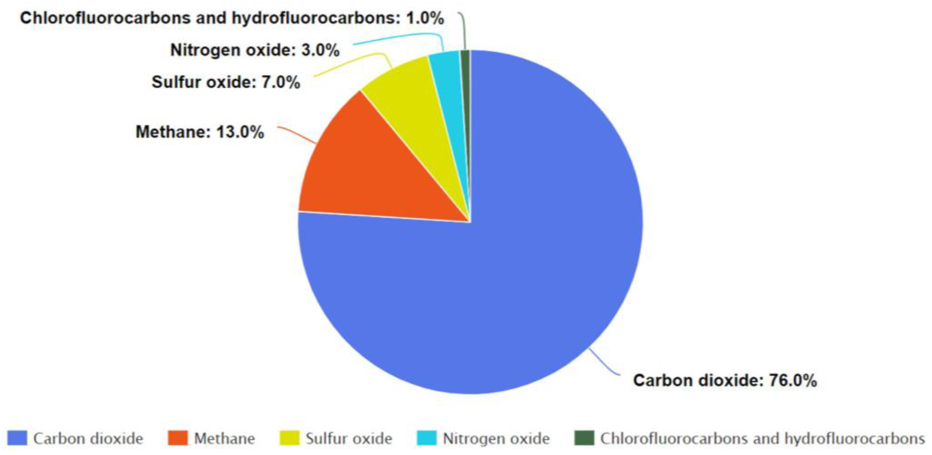
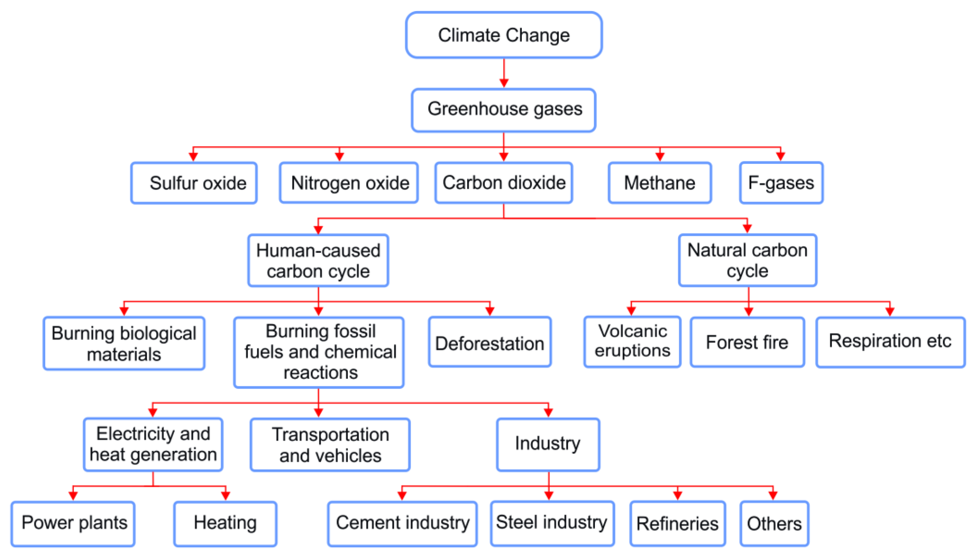
1.1. The Problem with CO2 Emissions

In the 21st century, there is no doubt that the world is facing the environmental challenge of climate change that has already started its impact on the ecosystem. Greenhouse gas emissions play a crucial role in all global environmental issues. Carbon dioxide is one of the major causes of climate change and corresponds to approximately three-quarters of total greenhouse gases in the atmosphere, as shown in Figure 1 [1,2].
CO2 emissions mainly come from both natural and anthropogenic sources. Volcanic eruptions, forest fires, the breathing of living organisms, decomposition of organic matter, and ocean release are the most common examples of natural causes, while human activities such as the combustion of biological materials, fossil fuels (primarily coal, natural gas, and oil), and deforestation are all responsible for the rest of the CO2 emissions. Although human-caused CO2 emissions are significantly smaller than natural emissions, they have disrupted the natural balance maintained for thousands of years prior to human intervention [3]. In order to keep the balance at a reasonable level, the human factor of climate change needs to be minimized.
The Paris agreement, ratified by 196 parties in response to the climate conference held in Paris in 2015, came into force with the aim of maintaining the global temperature increase under 2 °C since the period of pre-industrialization [4]. According to NASA Global Climate Change, in recent decades, the world is experiencing its highest level of CO2 emissions, with an increase of about 50% related to human activities since the beginning of the industrial revolution [5]. Despite the unexpected drop in CO2’s share in the atmosphere in 2020 by 5.4%, possibly due to COVID-19, in 2021, the global concentration of carbon dioxide in the atmosphere almost returned to a slightly lower level than its record in 2019 and continues to rise [6]. Currently, the atmospheric concentration of CO2 has reached over 419 parts per million (ppm), compared to the historical 800,000-year highest CO2 level of approximately 300 ppm in 1950 [5]. It is even estimated to increase above 1300 ppm by 2100. This increase in CO2 concentration is expected to be associated with a temperature rise of 4 °C if no actions are taken to reduce emissions [7].
In early November 2021, during the 26th annual Climate Change Conference held in Glasgow, UK, the participating 197 countries agreed to a new deal of the Glasgow Climate Pact. This Pact reset the goal of the Paris agreement which is to keep the increase of global temperature under 2 °C above the pre-industrial levels and urged to limit the temperature growth to even 1.5 °C so as to take rapid actions in the depletion of global greenhouse gas emissions by 2030. The final decision of the conference was the first to mention fossil fuels as a driver of climate change [8].
Fossil fuels as a driver of climate change are mainly used in the energy and industrial sectors that are responsible for more than half of the global CO2 emissions [9]. Over the last few decades, considerable amounts of CO2 have been released into the atmosphere as a result of electricity generation, cement and steel manufacture, oil and gas refineries, and the use of fossil fuels in many households [2]. These are illustrated in Figure 2, which provides an overview of the main roots of human-related CO2 emissions, and solutions for CO2 emission reductions are proposed in the upcoming paragraph.

1.2. Solutions for CO2 Emission Reductions

In general, while renewables maintain domination in decreasing emissions, it is uncertain if their falling prices will render other options such as CCSU [10]. Reaching zero carbon emissions by 2050 requires rapid actions in both CO2 emission reductions from the large emitting sources by applying CCSU and switching to sustainable energy systems step by step. Therefore, there are mainly three options to mitigate climate change by minimizing CO2 emissions, as shown in Figure 3.
According to the systematic analysis above in Figure 2, climate change by human activities is highly dependent on the energy produced by burning fossil fuels. The world’s energy demand and industrial activities increase in relation to global population growth [11]. Therefore, for a sustainable and healthy society, a reliable, environmentally friendly, and efficient energy supply, such as solar, wind, geothermal, hydro, and biomass energy with a green industry is required now more than ever before [12]. We are, however, on the pathway to making the switch from fossil fuel to sustainable energy, which may take a number of decades because of several challenging factors, including the imbalance between energy demand and the existence of renewable energy resources, price and supply fluctuations, technical limitations, and innovative technologies [13]. Thus, a combination of CCSU during the transition to sustainable energy sources cannot be neglected or underestimated.
CCSU is assessed as a promising strategy to mitigate climate change by decreasing the atmospheric concentration of CO2 from both power and industrial points [14,15,16,17]. The major human-related sources of CO2 emissions are from the industry, transportation, and power generation sectors. Unfortunately, extracting CO2 from a conventional transportation source is unfeasible with existing technology, while research is ongoing in this area. Large point sources, such as fossil fuel power plants, the cement and steel industry, chemical plants, etc., should be the main target of capture with existing technology [18].
Generally, pre-combustion, oxy-fuel combustion, and post-combustion capture are three primary approaches to the separation of CO2 from flue gas [19,20].
Post-combustion CO2 capture (PCC) is the most mature and already commercialized approach at a large scale [21]. In post-combustion capture, carbon dioxide is formed mainly with water vapor, nitrogen oxide, sulfur dioxide, and CO2 in different ratios by burning fossil fuel. Then, CO2 is captured from the flue gas before releasing it into the atmosphere [20]. There has been increased recognition of the post-combustion capture approach in the scientific field due to its simplicity to deploy to existing plants, as there is no need for a significant change to the combustion block [19].
PCC systems should be designed according to the emission source specifications, while maximizing process efficiency and minimizing emission reduction costs. Given the wide range of plant sizes and exhaust gas specifications applicable to different emission sources, it is unlikely that a single CO2 capture technology will be the best solution for all cases. Therefore, it is convenient to consider several technologies to effectively design the process and select the most efficient and cost-effective option to serve the purpose. It should be also considered that the carbon capture unit normally requires the pre-treatment of the flue gas stream, and therefore it is quite often installed after purification systems such as denitrogenation, desulfurization, and removing dust from the exhaust gas [22].
Post-combustion carbon capture can also be classified as solvent-based absorption, cryogenic separation, bio-fixation, membrane separation, solid adsorption, and calcium looping based on their capturing principles (see Figure 4).
Absorption-based carbon capture relies on the principle that CO2 in the feed gas is transferred into the liquid phase by selective absorption in a solvent. Solvent-based carbon capture is the most commercially available technology. For instance, amine-based absorption has many advantages such as capturing CO2 from low CO2 partial pressure flue gases, above 98% CO2 product purity, and solvent recovery rates up to 95%. As for adsorption, this process is a chemical or physical process in which molecules, atoms, or ions are captured by a solid adsorbent. Adsorption includes attracting CO2 molecules of flue gas on the adsorbent surface. In terms of cryogenic CO2 capture, it is a physical separation of CO2 based on the differences between the boiling and the desublimation points of CO2 in the gas mixture. In this process, CO2 is liquefied by condensation at low temperatures and separated from the flue gas. Cryogenic separation technology can obtain higher CO2 purity and recovery (99.99%) than other technologies. A calcium looping (CaL) system is a solid looping-based carbon capture system that can be easily retrofitted into the power and industrial sectors. This system uses calciner/carbonator reactors to remove CO2 from flue gases using solid calcium oxide (CaO)-based sorbent and regenerate the sorbent back [23]. The carbon bio-fixation method provides natural CO2 incorporation into biomass at a relatively low cost in terms of energy. Photoautotrophy and chemolithotrophy are natural mechanisms that have resulted in the consumption of CO2 biologically [24]. Algae-based CO2 utilization, among others, can be a promising route that uses photosynthesis to capture CO2 from flue gas for carbon fixation.

1.3. Membrane Technology as Promising CO2 Capture Method

New carbon utilization techniques, novel liquid solvents and adsorbents, and membrane materials are being recognized as new CCSU methods. Among them, membrane technology is the fastest developing, in terms of its promising performance. Membrane processes are now one of the most important technologies for industrial separations and are anticipated to play a crucial part in the development of sustainable production systems in the future. Membrane separation belongs to the generation of advanced separation processes following thermal processes, such as distillation and evaporation, and phase processes, such as absorption, adsorption, and extraction [25]. Membrane-based separation is advantageous compared to other methods, with its relatively low environmental impact and the simplicity of scaling up. Apart from that, it can be operated in a continuous system without a need for any solvent/sorbent and its regeneration is preferred by industry over conventional technologies. For these reasons, membranes have been implemented to not only gas separation processes but also several different sectors, including waste-water treatment, natural gas processing, membrane crystallization, pharmaceutical and chemical processes, biogas purification, CO2 capture, and other separation processes. The following sections provide more details about membrane separation in PCC, membrane classification, technological maturity of membranes, current challenges, and research advances.

1.4. Advances and Novelty of This Review with Respect to the Current State of the Art

This paper provides a detailed systematic analysis of the problems with CO2 emissions and pathways to CO2 emissions reduction. This is followed by a brief overview of the current state of membrane-based CO2 capture technologies, focusing on the bibliometric analysis and different CO2 separation techniques. In addition, this review covers updates for membrane-based carbon capture and other major PCC technologies from a broad viewpoint highlighting their main advantages and drawbacks. Apart from that, different types of membrane materials and their gas separation performances, role of membranes, pros and cons of using membranes in PCC, and existing problems based on the real application of membrane technologies are discussed. Updated TRLs of these PCC technologies are provided and discussed with the latest advances and progresses in the field. Finally, various PCC technologies are compared with membrane separation technology based on technological maturity, scalability, economic, and environmental aspects. The technological and economic suitability of each method to the current CO2 emitting point sources is also estimated.

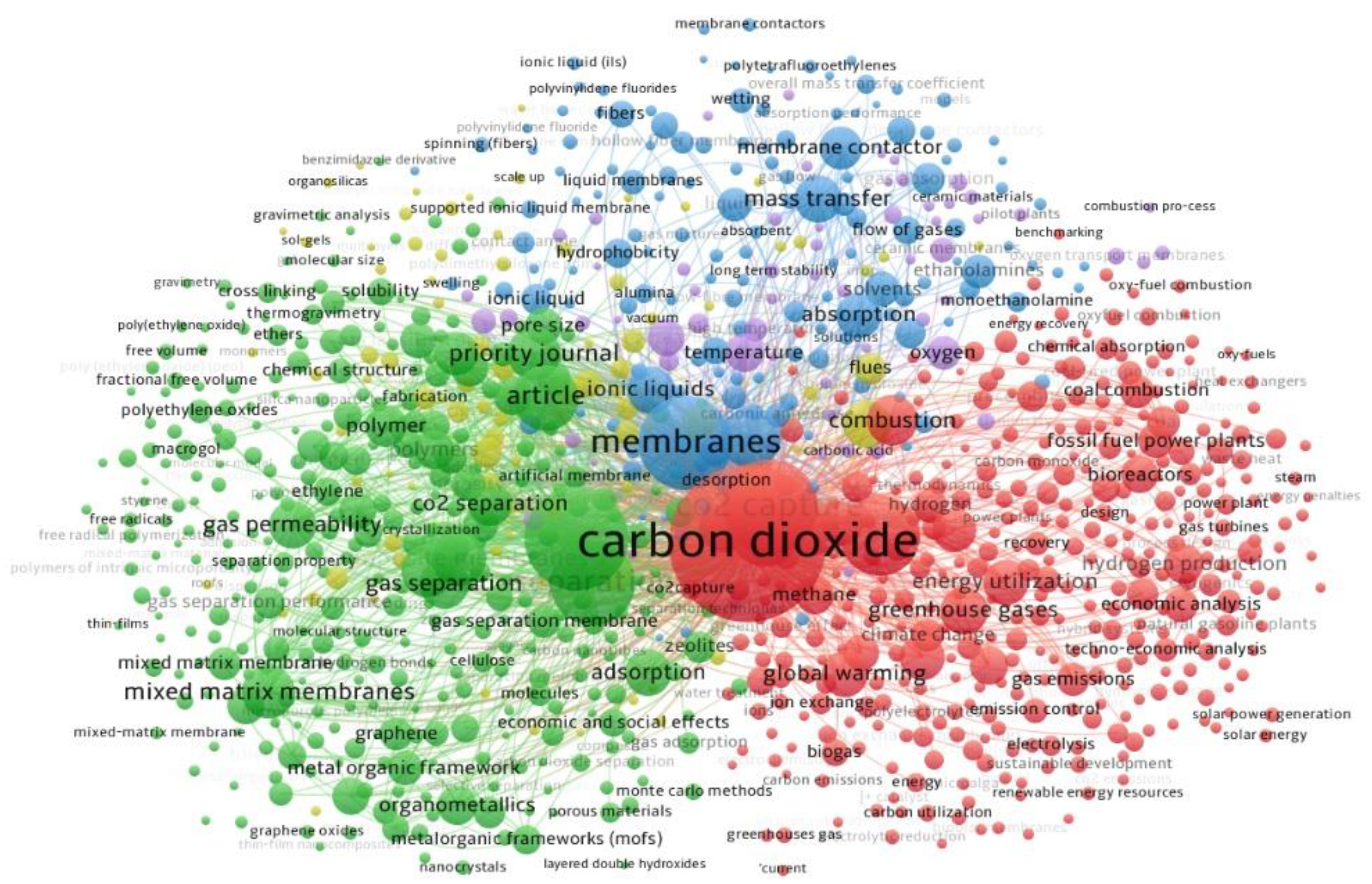
2. Search Criteria and Bibliometric Analysis

Bibliometric analysis is a statistical method that quantifies all forms of information carriers and is used to sort out the relationships between search data, as well as clarify the most important ones [26,27]. It is a widely used method for determining a field’s development [28]. Bibliometric analysis and data mining are conducted to study the state of scientific research in the field of membrane-based CO2 capture in recent years. For analysis, scientific documents, such as research articles, book chapters, review and conference papers, notes, and business articles, were collected by searching the Scopus web search engine under the terms “membrane CO2 Capture”.
Scientific documents published in the last 10 years were analyzed by document type, number of citations, and keywords. Initially, the scientific works from 2013–2017 and 2018–2022 are compared. Comparative analysis shows that scientific research in this field is developing rapidly. For example, in the period of 3 years between 2020 and 2022, the number of published scientific papers is more than the number released in the 5-year period from 2013 to 2017. This can be explained by the fact that the latest global climate change actions, particularly the Paris agreement in 2015, led to significant attention for environmental protection to become a trend in the scientific network. Between 2013 and 2017, 974 scientific documents were published, followed by 1422 in subsequent years. In order to identify the latest research in the field of membrane-based CO2 capture, we refer to the documents published in the years 2017 to 2022.
As shown in Figure 5, articles make up about 74% of the Scopus search results. Conference papers, reviews, book chapters, and other documents account for 11%, 10%, 4%, and 1%, respectively. The large number of scientific articles in the published documents indicates that intensive research is going on in this field.
The complete number of citations for scientific documents is 55,962 and the works with the largest number of citations are devoted to recent advances in CO2 capture and membrane separation. We imported the data into the visualizing bibliometric network tool (VOSviewer 1.6.17) to create a network map of keyword co-occurrence. A keyword co-occurrence network, also known as a semantic network, is a bibliometric data analysis method that includes a graphic visualization of possible relationships between searched keywords [29]. As can be seen in Figure 6, all keyword co-occurrences consist of 6 clusters with different colors and 978 items.
Nodes represent keywords in the network map, whereas arcs represent co-occurrence relationships between nodes and indicate that they have become linked [30].
The most often occurring keywords, such as ‘carbon dioxide’, ‘gas permeable membranes’, ‘membranes’, ‘carbon capture’, ‘composite membranes’, and ‘mixed matrix membrane’ are shown with larger labels and nodes in each cluster.
The results of the bibliometric analysis show that scientific research in membrane separation in recent times has focused mainly on the development of membrane materials, improving membrane performances, and using membrane in hybrid separation systems.

3. Typical Industrial Sectors and Stream Characteristics for CO2 Capture

As mentioned in the introduction, energy, industry, and transportation are the largest CO2-emitting sectors, in which the contribution of global greenhouse gas emissions reached almost 90% in 2019 [31]. Massive electrification of transportation points has great potential to reduce the CO2 footprint from this sector in contrast to the additional increase in the demand for power generation [32]. As a result, energy and industrial facilities keep their domination as substantial CO2 emission sources that can be captured and utilized by CCU technologies.
Based on the fuel type, CO2 emitters in power generation involve coal, oil, and natural gas-fired power stations, and waste-to-energy power plants. Apart from these, the industrial point sources of CO2 constitute cement plants, crude oil refineries, iron, steel, and petrochemical factories [33]. Table 1 shows the typical industrial sectors and stream characteristics of these sectors.
Referring to CO2 capture from power plants and industrial sectors, the characteristics of the outlet flue gas stream are one of the main factors to be considered regarding the amount of CO2 in the stream. The pressure of the exhausts is nearly the same for all types of power plants at atmospheric pressure, in contrast to the different levels of temperature depending on the various conditions. For instance, in natural gas-fired combined cycle power plants, the temperature is not lower than 90 °C, in order to avoid condensation and damaging the chimney, and not above 110 °C, in order to utilize as much heat as possible. However, for most CO2 separation applications, the flue gas is required to be between the temperatures of 40–60 °C. In terms of stream compositions, coal- and oil-fired power stations have similar products of combustion with higher amounts of impurities such as SOx and NOx in comparison with natural gas combustion products, which are relatively clean with trace amounts of NOx. Since the CO2 content in the flue gas plays a vital role in the capture cost [33,34,42], coal- and oil-fired plants have advantages, with higher amounts of CO2 content, at an average of 12–14 mol%, compared to natural gas-fired power plants and combined cycle counterparts, at an average of 8–9 mol% and 3.5–4.5 mol%, respectively. From this perspective, the cost of CO2 capture for combined cycle power plants is more expensive than others due to the low CO2 concentration in the stream, although the efficiency of the plant is the highest. Coal-fired power stations have, however, the largest contribution to global CO2 emissions, at around 10 Gt annually among all other types of power plants.
As for the cement industry, since the CO2 emissions come from the energy-intensive limestone calcination process [58] and the combustion of fossil fuels, the cement plant flue gases have a high carbon content, at an average of 18–22 mol%. The temperature of the flue gas in cement production can be between 150–350 °C depending on the type of raw material and preheating stages. High-temperature flue gas must also be utilized with appropriate techniques to cool down it prior to flue gas decontamination. The steel production industry is the largest fuel consumer and emits a high CO2 content in exhaust gas, similar to cement production. Steel and cement industries are responsible for 14–19% of global greenhouse gas emissions (annually, 2.6 and 2.3 Gt CO2 emissions, respectively). For this reason, methods and techniques of decarbonization in these industries are being developed. When it comes to other CO2-emitting industries, they also emit CO2 resulting from fuel combustion and chemical reactions. However, it can be seen that the annual CO2 emissions are much lower compared to fossil fuel power plants, cement, and steel industries on a global scale.

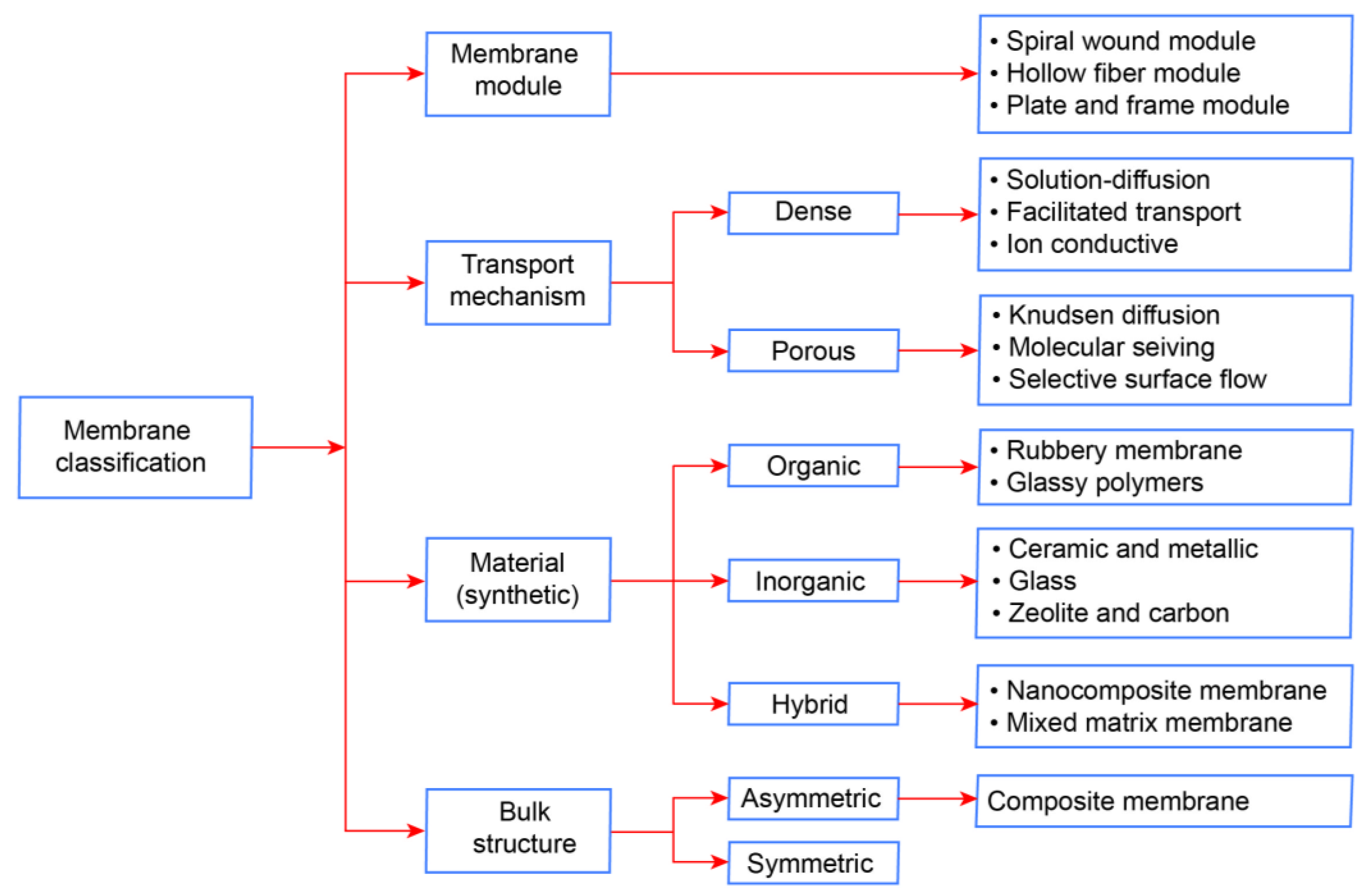
4. Membrane-Based CO2 Capture Technologies

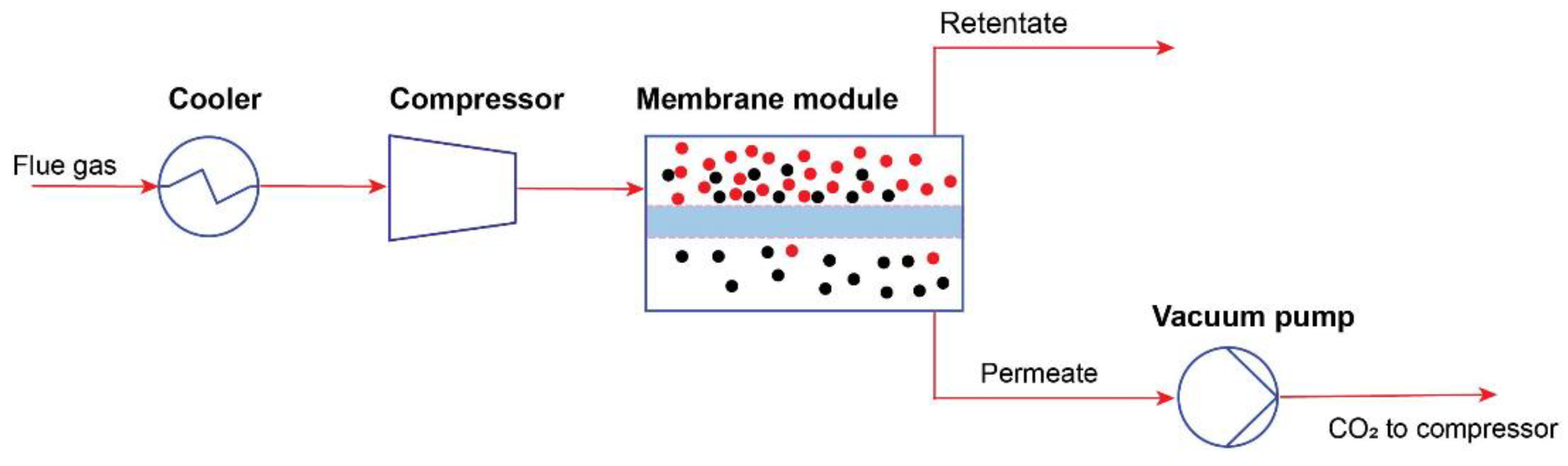
4.1. Membrane Separation

The membrane separation process is a process that uses a special module called a membrane to separate gases in a gas stream by rejecting contaminants (retentate) and passing desired components (permeate) through the membrane module shown in Figure 7. In this process, pre-treated flue gas containing CO2 is sent to the high-pressure side of the membrane, and CO2 is recovered from the low-pressure side.
Membrane separation could be a promising technology with operating parameters that go beyond current technologies, as they often feature a small footprint, easy scaling, integration into existing technologies, low operating costs, as well as low energy consumption. Membrane separation in PCC is expected to be a technology that can compete with benchmark absorption. There are mainly three types of membranes based on its material, which are organic (polymeric), inorganic (non-polymeric), and mixed matric membranes (hybrid organic and inorganic) [65]. Apart from that, membranes can also be used as a membrane contactor, enhancing the solvent-based CO2 capture processes. Regarding the performance of the membrane, it is highly related to the selectivity and permeability, which is the rate of passive diffusion of molecules through the membrane. In this CO2 capture method, mainly hollow fiber, a spiral wound, and flat sheet membrane modules are used [66]. The different classifications of membrane technology are shown in Figure 8.
Even though there are several commercial applications of membranes in different fields, the number of commercial membranes special for CO2/N2 separation is limited. For instance, Kárászová et al. [68] have reviewed various applications of commercial and emerging lab scale membranes which have been tested with flue gas. They also emphasized the existing achievements and barriers of potential membranes and evaluated their conditions of competitiveness with monoethanolamine (MEA) absorption. Apart from that, Chen et al. [69] reviewed three types of polymeric, non-polymeric, and mixed matrix membranes based on pre, oxy-fuel, and post-combustion CO2 separation, and concluded that more pilot plant tests should be implemented under real flue gas conditions of different fuel combustion products in post-combustion CO2 capture.

4.1.1. Organic Membranes

In post-combustion CO2 separation, organic membranes are prepared by polymers such as polyacetylene, polysulfone, polycarbonates, polyetherimides, polyaniline, poly(phenylene oxide), poly(ethylene oxide), and polyvinylamine. Although the polymer-based membranes are used at low temperatures, and plasticization and swelling by water are the main issues, their relatively low cost, diversity, and easy control of processing can greatly outweigh their drawbacks. Additionally, developing the polymer and the combination of the chemical elements during the membrane preparation can be manipulated, which gives an extra advantage for this type [69,70]. In terms of transport mechanism, facilitated transport and solution-diffusion (non-facilitated transport) membranes are reported as the most widely applied and recognized in post-combustion carbon capture [65]. In the solution-diffusion transport mechanism, CO2 dissolves into the dense membrane followed by its diffusion throughout it. This mechanism is usually divided into rubbery, glassy, and co-polymeric membrane types which have different gas separation performances. For instance, rubbery polymeric membranes have higher permeability with inadequate selectivity, while the glassy type has opposite characteristics [71]. As for the facilitated transport membranes, CO2 molecules are attached by reactive carriers, forming a temporary product via reversible chemical reaction. Unlike solution-diffusion transport, facilitated transport membranes have relatively higher selectivity and permeability due to the enhancement by both aforementioned transport mechanisms [72]. Facilitated transport membranes are seen as one of the promising technologies for the flue gases from both power and industrial sectors, owing to their ability to separate CO2 in low partial pressure.

4.1.2. Inorganic Membranes

Non-polymeric membranes are usually based on ceramic, metal, glass, carbon, and zeolite, which can practically provide better chemical and thermal stability than those of polymeric counterparts. For instance, alumina, titania, and zirconia are considered as the best choice for higher temperatures and harsh conditions, in spite of their relatively high cost [73,74]. Regarding the separation of CO2 from flue gas, mainly N2, since the dipole moments of both CO2 and N2 are zero, the ion transport mechanism is not applicable in this case. It should also be highlighted that their kinetic diameters are quite similar in size, which are 0.333 nm and 0.357 nm, respectively. Inorganic membranes can be mesoporous, microporous, and dense in type with regard to the purpose of use. On the one side, the permeability of microporous membranes is low with higher selectivity, while the characteristics of mesoporous membranes are opposite. Dense membranes, on the other side, have superior performance with their selectivity compared to mesoporous and microporous, though their permeability is lower [75]. According to Li et al. [76], several types of inorganic membranes, particularly zeolites, have reached the commercially interesting area. However, further cost reduction is needed to deploy them commercially in CO2 capture processes. Moreover, the processing of inorganic membranes is challenging and they tend to break easily without plastic deformation.

4.1.3. Mixed Matrix Membranes

Many efforts to reach better performance of selectivity/permeability trade-off relationship on Robeson upper bounds have led to the fabrication of new a membrane technology by hybrid organic and inorganic (mixed matrix) membranes, further improving the polymeric membranes. Mixed matrix membranes are prepared from a polymer matrix filled by inorganic fillers, such as carbon nanotubes [77], metal organic frameworks [78], and zeolites [79], enabling them to take an advantage of both organic and inorganic membrane properties. Several review papers have analyzed the mixed matrix membranes and compared them to the traditional polymeric counterparts. For example, Kamble et al. [80] thoroughly reviewed and analyzed the recent works in the field of mixed matrix membranes and their inorganic fillers, emphasizing advances and the current problems of inorganic fillers materials. They also discussed the advantages and drawbacks of organic, inorganic, and mixed matrix membranes in the following Table 2.

4.2. Hybrid Membrane Systems

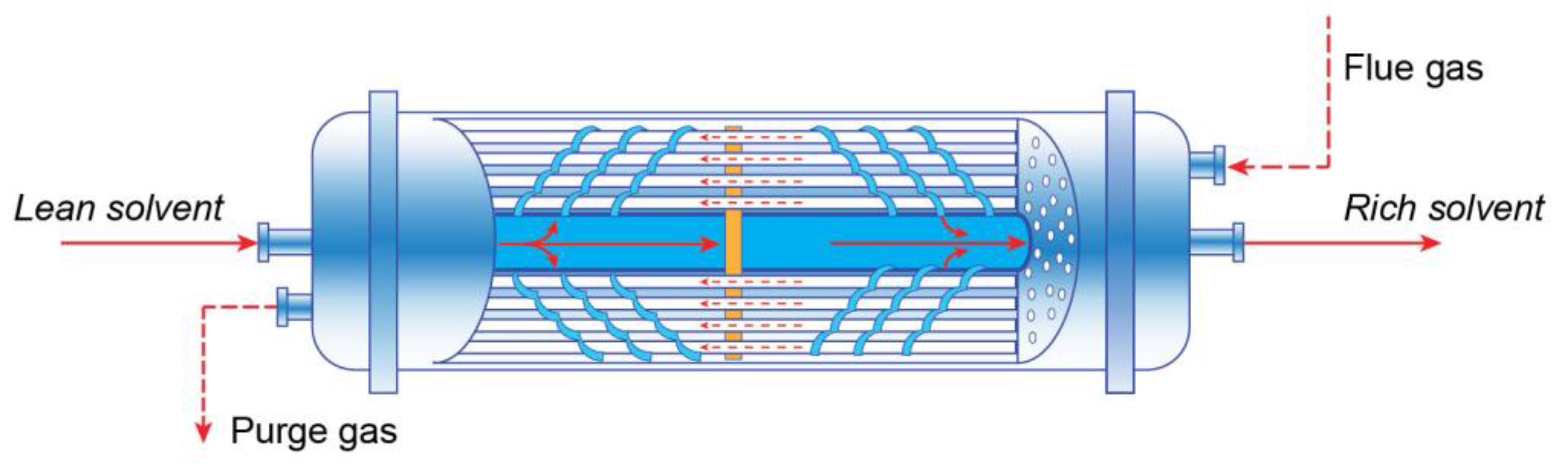
4.2.1. Membrane Contactors

Another application of membranes in CO2 capture processes is membrane contactors, which are a combination of membranes with solvent sorption. Membranes can be used at the gas–liquid interface, separating two phases by allowing only CO2 molecules pass through the membrane (dense or microporous) to the solvent side (See Figure 9) [81]. Generally, the hollow fiber and flat-sheet membrane contactors are two of the most researched technologies. In practice, the hollow fiber module is commonly used. In terms of the type of membrane material, polymeric or inorganic membranes could be chosen in response to the conditions applied. Since the process is based on the combination of membrane and solvent absorption, there are some requirements for the selection of membrane material and appropriate absorbent, including the limitations of both technologies. For instance, the selected material should provide the features of high hydrophobicity to minimize the wetting effects, thermal and chemical stability to maximize the durability, and high porosity to minimize the mass transfer resistance [82]. Absorbent characteristics also play an important role, as they have a direct influence on the process efficiency and economic aspects [83]. The commonly used solvents in this process are alkanolamines [84], amino acid salts [85], inorganic solvents [86], ammonia [87], and ionic liquids [88,89].
Membrane contactors are considered a promising technique since they allow for the avoidance of several issues such as channeling, flooding, and foaming in the conventional packed and tray columns. Apart from that, the equipment size of the column can significantly be decreased, up to 70% in size and 66% in weight, generating 4–15 times higher mass transfer area per unit volume over the traditional technique [81,91]. However, in addition to wetting and fouling of the membrane, one of the main problems of this method is extra resistance in mass transfer due to the availability of the membrane between these two phases.

4.2.2. Hybrid Membrane-Absorption

Another possible application of membranes is to use them as an additional unit in the absorption process in order to improve the driving force of the mass transfer, further concentrating CO2 in the flue gas. This hybrid technique was initially studied by the University of Texas at Austin in collaboration with Membrane Technology and Research [92]. They integrated the selective membrane recycle unit into the absorption process in series and parallel methods. According to the results, through the best parallel configuration, the size of the absorber and flue gas flowrate can be reduced by nearly half, increasing the CO2 content in the flue gas from 13% to above 23%. Apart from that, several other studies have been undertaken in this field with respect to design and operational variations [93,94], economic cost evaluation [95], and possible applications in natural gas combined cycle (NGCC) power plants in selective exhaust gas recirculation (SEGR) [96,97]. Overall, this technique can be a feasible option for low CO2 partial pressure flue gases, particularly coal-fired and NGCC power plants (around 4% and 12–14% by volume, respectively), as long as more pilot plant tests are implemented under the real flue gas conditions.

5. Comparison of Membrane and Other Technologies for Post-Combustion CO2 Capture

This section compares the opportunities and challenges, technological maturity, and scalability of post-combustion membrane CO2 separation with other alternatives. This is the best assessment to determine the current status of membrane separation technology for post-combustion CO2 capture by comparing it with other available methods. Table 3 summarizes the overall advantages and disadvantages of different post-combustion CO2 capture technologies.

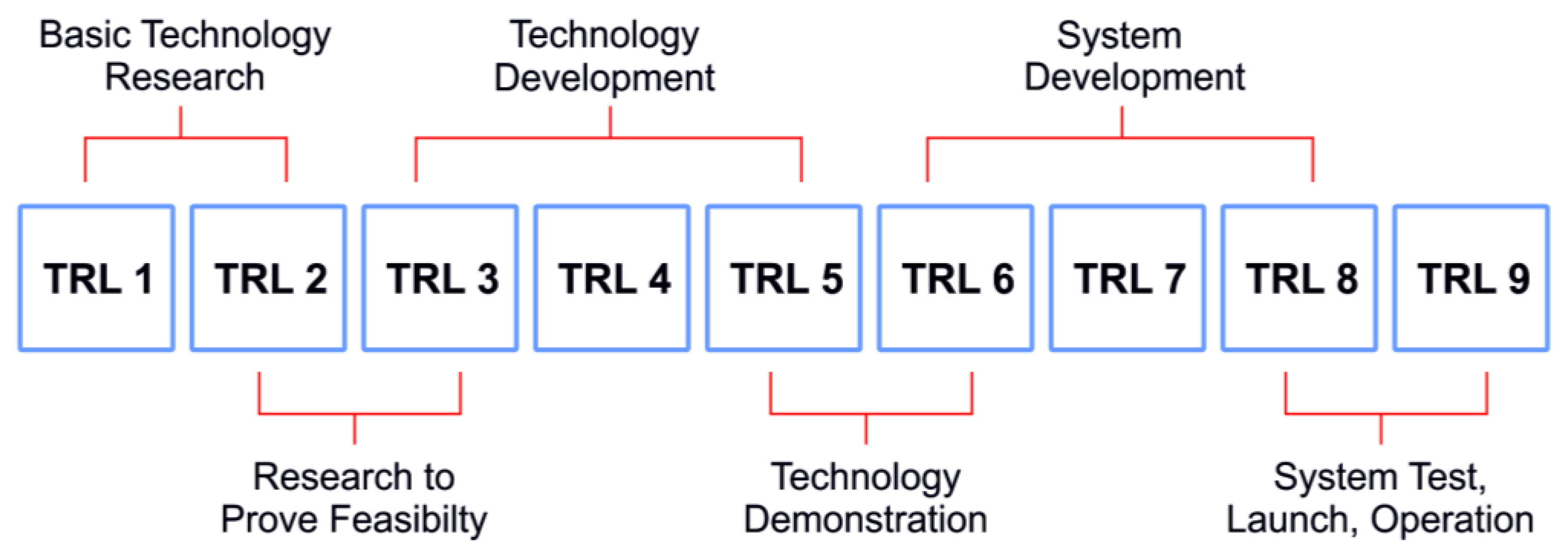
5.1. Technology Readiness Level and Scalability

Technology readiness levels (TRL) are the technological maturity assessment of the technology developed by The National Aeronautics and Space Administration (NASA) that dates back to its origin in the 1970s. TRLs are divided into nine levels, starting from initial observations and concepts at TRL 1 and at TRL 9, at which the technology is the most mature [101]. The general schematic of the TRL assessment is shown in Figure 10. The TRL levels of various post-combustion CO2 capture technologies are summarized in Table 4. In addition, the current and near-future scalability potentials of these technologies are evaluated based on recent information.
Although carbon capture and storage technology (CCS) is one of the solutions to the climate change problem, there are several challenges from an economic point of view involving the interconnection between the emitting points and CCS technology. According to Global CCS Institute [102], there are 30 commercialized carbon capture, storage, and utilization facilities with a global CO2 removal potential of around 43 million metric tons of CO2/year. In addition to this, 164 other CCS projects are in the stage of construction and development. If all announced CCS facilities are launched, the potential of CO2 removal will increase multiple times. However, several factors, such as the current global economic crisis, the relatively low cost of CO2, project installation, and operating costs, may lead to the suspension of the efforts to launch these facilities. For example, the Petra Nova CCS project, capable of 1.4 million metric tons of CO2 removal annually, was shut down on 1 May 2020 due to the significant decrease in the price of oil, although around 1 billion USD was already spent on this project [103].
Table 4. Scalability and TRL performances of CO2 capture technologies.
MethodScalabilityCommentTRLReference
Absorption
Amine-based absorptionLargeAmine-based absorption (monoethanolamine (MEA), methyldiethanolamine MDEA) was fully commercialized and used on large scale (power and industrial sector)9[104]
Chilled ammonia process (CAP)LargeThe chilled ammonia process was demonstrated using flue gas streams (16% and 3.6% CO2)7[105]
Ionic liquid absorptionEarly to assessAlthough there are a few field trial tests, research and developments are mainly at lab scale2–4[106,107]
Piperazine solventLargePiperazine (PZ) solvent for capturing CO2 from 4% CO2 flue gas was tested at natural gas combined cycle (NGCC) power plant7–8[108]
Phase-change solvent absorptionSmall & mediumPhase-change solvent absorption was tested at packed bed pilot plant4–5[109]
Adsorption
Vacuum swing adsorption/Pressure swing adsorptionLargeAlthough this adsorption method has already been commercialized by Air Products in hydrogen production plant, in post-combustion CO2 capture, it is not mature yet2–5[110]
Temperature swing adsorptionMediumLarge pilot tests to FEED studies for commercial plants5–7[111,112]
Electric swing adsorptionEarly to assessThis technique is still at lab scale3[113]
Membrane separation
Polymeric membranesSmall & mediumPolymeric membranes for post-combustion CO2 separation are in transition from pilot scale to demonstration with high possibility of commercialization6–7[114,115,116]
Inorganic membranesEarly to assessDue to the complexity of material processing and relatively high cost, this membrane is mainly tested at lab-scale3[117]
Membrane contactorsMedium to large scaleMost of the promising membrane contactors at lab scale development with a few of them has been tested at pilot scale4–6[108,118]
Hybrid membrane-absorptionMedium to large scaleHybrid membrane-absorption is being evaluated to achieve low-cost CO2 capture than traditional amine-based capture system. Especially for low CO2 concentration flue gas3–4[106,119]
Polymer mixed facilitated transport membranesSmall to medium scaleThe pre-pilot field testing was implemented at the cement industry6–7[120,121]
Other post-combustion carbon capture technologies
Cryogenic packed bed capture/Anti-sublimation systemSmall to medium scaleAlthough this technology is mature for CO2/CH4, it is still uncertain to apply for post-combustion flue gas3–4[122]
Calcium loopingLarge scaleDemonstrated pilot plant using oxy-fuel calcination5–7[123,124]
Carbon bio-fixationMedium to large scaleMicroalgae cultivation and biomass co-firing for power generation4–6[34,125]
TRL levels are summarized focusing on only post-combustion carbon capture performances. Current and near future scalability potential is assessed for each technology with respect to the evaluation of references and individual estimation.
In this section, since the cost estimation of CCS technology relies on industry and fuel type, flue gas contents, retrofitting opportunities, carbon capture method [126], utilization and storage pathways [127], and many other factors, we will mainly discuss the TRL level and scalability performance of post-combustion carbon capture and utilization and their comparison by each technology in the subsequent sections.
Post-combustion carbon capture based on an amine absorption technology is fully commercialized (TRL 9) for large-scale applications and is used as a benchmark rather than other liquid solvents, piperazine (PZ), chilled ammonia, ionic liquids, alkaline solutions, and blended solvents [128], and other capture technologies. Amine, mostly MEA, absorption needs a significant quantity of heat for rich solvent recovery and power for CO2 compression, as well as for electrical equipment. The CO2 capture cost for the absorption process ranges between 50 USD CO2/ton and 100 USD CO2/ton depending on industry and solvent type [129,130,131]. The second-generation post-combustion absorption technologies involve the PZ solvent-based absorption (TRL 7-8) and the chilled ammonia processes (CAP) (TRL 7). The PZ chemical absorption has been tested at the NGCC power plant and is ready to capture CO2 in a large-scale application. The CAP is moving toward the commercialization stage after testing in different flue gas streams and is suitable for large-scale applications. An ionic liquid (IL) absorption technology is still in the research and development stage (TRL 2-3). ILs should be developed to overcome challenges such as toxicity, solvent cost, viscosity, low absorption capacity, corrosive nature, and hygroscopicity. Novel phase-change solvents (TRL 5-6) are currently being developed at a low-rate pilot scale in a relevant environment [109] and are expected to be available for commercialization in the next years.
While cryogenic separation for post-combustion carbon capture is the best technology to obtain pure CO2 in liquid or solid form, it is not yet scaling up (TRL 3-4) in post-combustion carbon capture due to the high demand for energy in the low CO2 composition [108,122]. Apart from that, flue gas impurities, particularly water, need to be removed in order to avoid blockage issues caused by solid ice formation of water at low temperatures, which further increases the cost of separation. Therefore, it should be noted that this technology might only be feasible when the cold energy source, such as liquefied natural gas vaporization process, is available at near locations [117].
The calcium looping process can capture CO2 from a large-scale power plant and other industrial flue gases [132]. Due to the high temperature of the processes in the carbonator/calciner fluidized bed reactors and additional requirements for oxygen, there are difficulties in implementing the calcium looping process from an economic point of view. For instance, in carbon capture from natural gas combined cycle power plant flue gases, the CO2 capture cost of calcium looping is between 90 USD CO2/ton and 100 USD CO2/ton, which is significantly more than the benchmark amine (MEA) capture process [133]. However, this technology seems more attractive because of the inexpensive natural limestone, the possibility of diverting used CaO to cement production, power/steam generation from waste heat, and its being much less hazardous to the environment compared to solvents.
Regarding CO2 bio-fixation, CO2 can play a crucial role in boosting algae and crop cultivation. Microalgae photosynthesis, from the scalability context, is possibly assessed as a medium or even higher scale technology, considering its significant limitations including large space requirement, wastewater availability, algae sensitivity to the impurities, and high cost of control. Unavailability of sunlight at nighttime also affects the efficiency of CO2 removal. However, it is considered as the best-fitting technique for flue gas streams with relatively low CO2 content, such as the flue gas from NGCC power plants, without affecting the efficiency of the plant [134]. CO2 consumption in greenhouses is becoming another trend for yield boosting in many countries. For instance, the Netherlands stands out as a country in which CO2 is used in greenhouses up to 6.3 Mt per year [135]. Although carbon bio-fixation is generally at low TRL levels [100,125], its estimation for the end of this decade is relatively large, as the demand for biofuels and bio-based feed products rises [136].
The adsorption process is assessed as a viable method for gas purification. When it is implemented in PCC, challenges occur related to flue gas characteristics. In terms of pressure-based sorbent processes, the suitability of these processes to CCS highly depends on CO2 content from an economic point of view. An energy penalty will be significantly higher at low CO2 partial pressure sources than other high CO2 partial pressure gas streams (hydrogen production, steel, and other industrial sectors) for PSA/VSA adsorption. Although the CCS facility based on a VSA (VPSA) was demonstrated (TRL 8–9) by Air Products at the steam-methane reformers (CO2 from syngas), this technology can be a feasible option to commercialize for post-combustion CO2 capture with higher CO2 concentration flue gases [108]. The temperature swing adsorption (TSA), particularly the Kawasaki Carbon Capture System [112] and Svante VeloxoThermTM Rapid Cycle Temperature Swing Adsorption [106], reached a demonstration-scale with innovative sorbents and adsorption reactors. In other emerging CO2 capture technologies by adsorption (TRL < 5), scientific research and development are being conducted in order to solve problems depending on the limited scale of sorbent capacity, selectivity under realistic pressure conditions, moisture sensitivity, and slow kinetics. In terms of adsorbent materials, zeolites and carbon-based solid sorbents are more mature than other adsorbents and are widely used in large-scale applications [137].
Membrane gas separation is becoming one of the promising options in CO2 capture from fuel combustion flue gases. Although polymeric membranes have already been commercialized in natural gas processing [106], in post-combustion CO2 separation, there are only three polymeric membranes so far that have been demonstrated on a pilot scale reaching the level of TRL 5–6. These are Polyactive® membrane by Helmholtz-Zentrum Geesthacht in Germany, Polaris® membrane by Membrane Technology and Research Institute in the USA, and fixed-site-carrier membrane by the Norwegian University of Science and Technology in Norway [116]. Nevertheless, there are still some major issues remaining when tested under real flue gas conditions. These problems include humidity-based membrane resistance, thermal influences on transport properties (permeability and selectivity), stability of the membrane layer for a long period, and the impurities of the flue gas [68]. However, in the last decade, significant progress has been made in CO2 capture using polymer matrix membrane processes. According to Janakiram et al. [115,121,138], water content in the flue gas is no longer an impurity, but it is a promoter. Humidity in the module can increase membrane permeability. They tested hollow fiber modules of hybrid facilitated transport membranes for flue gas coming from the cement industry. Membrane performance improved when there was more water in the flue gas stream. As for the inorganic membranes, they are still in the lab scale development, with TRL 3–4 [117], due to several problems related to the permeability of dense membranes, difficult processing, and high cost, as mentioned in the previous section. According to Jusoh et al. [139], the fabrication cost of membrane modules for zeolite is 150 times higher than polymeric hollow fiber membrane modules, at 3000 USD and only 20 USD per square meter, which leads to its limitations in industrial applications. In terms of hybrid membrane-absorption techniques, on the one hand, there are several field trial and pilot scale studies of membrane contactors in CO2 capture. However, membrane wetting and its compatibility with solvent still remain as the major issues. For instance, the latest pilot study of membrane contactors, reported by Scholes et al. [118], revealed that membrane contactors can be a feasible option for industrial applications, though the energy consumption in the pilot study is higher than conventional capture technique (less than 4.2 MJ/kgCO2) due to thermal losses in membrane modules and energy integration issues. Membrane separation integrated absorption technology, on the other hand, was assessed at a TRL of 4 as a conceptual study by the Global CCS Institute in 2021 [106]. Freeman et al. [119] conducted a bench scale study of hybrid membrane-absorption CO2 capture from coal-fired flue gas. In accordance with this report, in the hybrid system, CO2 concentration in the flue gas can be increased to around 20% using an MTR air-swept Polaris™ membrane module with 15% lower capture cost than the conventional amine technology result of the National Energy Technology Laboratory.

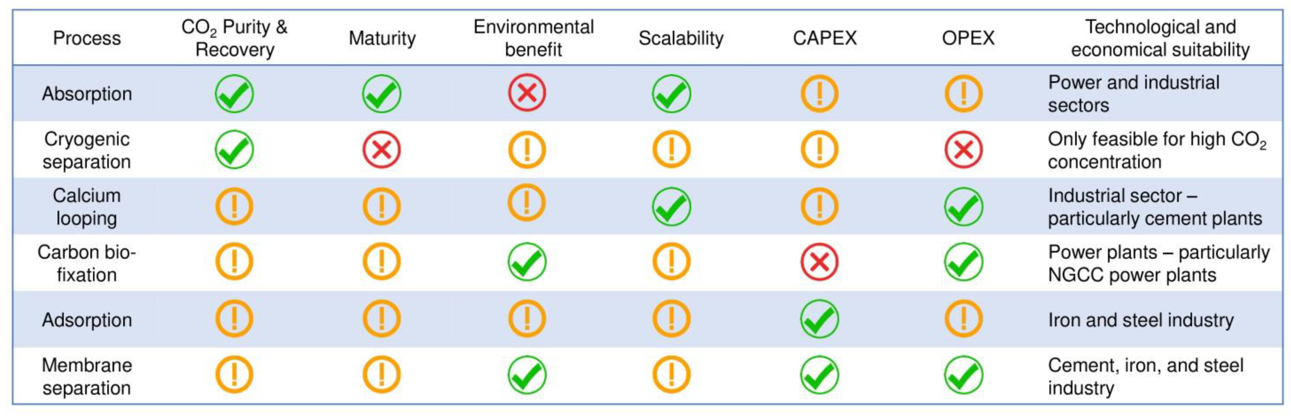
5.2. Overall Technology Comparison for CO2 Capture

Here is a general discussion about five different CO2 capture technologies and their comparison based on CO2 purity and recovery, scalability, TRL, capital expenditures (CAPEX), operational expenditures (OPEX), and environmental benefit without certain metrics. In order to carry out the best realistic comparison among these technologies, there are many factors and conditions to consider for each specific case and technology that makes the work more challenging. Therefore, the following discussion and comparison are conducted to make a general overview of the key highlights of each technology.
Regarding the captured CO2 recovery and purity, the cryogenic method is evaluated as the most suitable technology, capable of 99.99% product purity, since this process is based on obtaining CO2 in liquid or solid form at a very cold temperature. This technology has been applied in mainly air separation units, blue hydrogen production, natural gas processing plants, and biogas processing so far. Nevertheless, the challenges that the process is energy intensive and requires a high concentration of CO2 in the flue gas stream are hindering this technology’s commercial deployment and scalability assessment in the post-combustion field. Absorption, calcium looping, and adsorption (TSA) also have great potential to obtain a relatively pure CO2 product, but the equipment cost and operating cost also increase. Membrane separation and adsorption (VPSA) processes are not favorable in this context due to the necessity for multiple stage installation, which leads to additional CAPEX and OPEX. CO2 bio-fixation can be assessed for only CO2 recovery rate, which is quite a bit lower than other techniques, since the process directly utilizes the captured CO2.
From the scalability point of view, absorption by amines can be evaluated as the most reliable technology and capable of capturing CO2 at a large scale, followed by the calcium looping process, which is not fully mature yet. For example, Zanco et al. [140] performed a comparative study of absorption, adsorption, and membrane technologies, selecting the most mature and effective techniques under the same condition for all. According to the results, adsorption and membrane technologies are more cost competitive than the absorption process in terms of small-scale plants. However, at large scale plants and higher CO2 recovery rates, absorption is found to be the most cost-effective. Carbon bio-fixation can also be applied for large scale power plants without a need for flue gas pre-processing.
When the TRL levels are considered, as discussed previously, the number of techniques that have reached maturity is higher in the absorption process than others, followed by adsorption techniques. However, membrane separation (polymeric and mixed) is assessed as the fastest developing technology due to its wide range of characteristics that have not yet been studied well compared to the cryogenic separation method, which attracts the least attention in terms of commercial deployment in PCC. The following is Figure 11, which provides an overview of different technologies’ comparison based on five categories.
Regarding the overall CAPEX and OPEX, facilitated transport membranes (polymer mixed) can be more potent than other techniques due to their acceptance of water, which makes them unique among other membrane types [138], although this membrane is not commercially available and not fully mature yet. As membrane science has been developing rapidly in recent years, its advantages, such as easy scale-up, small footprint, and, particularly, lower energy consumption, can overcome the conventional benchmark absorption technology. In terms of carbon bio-fixation, this technique requires very high capital investment due to the large number of photobioreactors’ installation and large area requirements. In contrast, OPEX is relatively low, as the process goes at ambient conditions. Ca-looping also seems acceptable from the OPEX, since the sorbent (CaO) is relatively cheap, but the additional air separation unit leads to an increase in the CAPEX. However, in the case of amine scrubbing and solid sorption, the CAPEX and OPEX highly depend on which type of solvent or sorbent and techniques are used, their scalability, availability at low cost, site conditions, maturity level, and many other factors. For instance, in the MEA absorption process, the majority of the OPEX is connected to the solvent regeneration energy and its heat integration to the point source, followed by solvent loss and its degradation, while CAPEX varies in response mainly to the dimensions of the columns, packing or tray type, and heat exchangers based on the flowrate, CO2 partial pressure in the flue gas, purity requirement of CO2, and capture rate.
As for the environmental concerns, it is very difficult to evaluate without a rigorous lifecycle analysis of each technology. However, in general, carbon footprint of absorption with amines can be higher than other techniques since there is an extra emission of solvent, which has an even higher impact on the environment than CO2. Solid sorption, calcium looping, and cryogenic separations also possibly have more environmental stress (depending on the energy intensity and its source) than membrane separation and carbon bio-fixation, which are both considered as the most energy-efficient, with less of a carbon footprint.

6. Conclusions and Future Works

In this study, the recent research on membrane-based post-combustion capture and other PCC technologies has been discussed in terms of the types of technology available and their potential contribution to the abatement of CO2 emissions. In addition, the existing challenges and opportunities of using membranes in the decarbonization of power and industrial sectors are discussed.
In recent decades, CO2 emissions have reached their highest level, with an increase of nearly 50% related to human activities. Therefore, CCSU plays a crucial role in line with renewable energy to reduce CO2 emissions.
Regarding the results of the bibliometric analysis, scientific research in the field of membrane-based CO2 separation in recent years has focused mainly on the development of membrane materials, improving membrane performances, and using membranes in hybrid separation systems.
Aside from this, several important generalized conclusions can be drawn from this review:
  • Stationary CO2 emitters from the power sector and CO2 sources from industry are the first places where their emissions should be reduced.
  • CO2 content in flue gas plays a vital role from a technological and economical point of view.
  • According to current studies, membrane technology for PCC will play an important role in the near future, since there is a high possibility for further investigations of new membrane materials and optimization of existing ones.
  • The study comparison shows the overall best result for membrane technology in different categories, such as CO2 purity and recovery, maturity, scalability, CAPEX, OPEX, and environmental benefits.
  • As membrane studies on decarbonization of large emitters have been developing rapidly in recent years, its advantages involving small carbon footprint, easy scale-up, and, especially, lower energy consumption are expected to overcome the first-generation benchmark absorption technology.
  • Despite the scientific progress achieved, there are still challenges in the implementation of membranes in real conditions for PCC. These issues include humidity-based membrane resistance, thermal influences on permeability and selectivity, long-term stability of the membrane layer, and the tolerance for flue gas impurities.
  • The membrane gas separation method can be suitable for flue gases with higher CO2 content, such as cement, iron, and steel industry.
  • Large scale application of membrane technology, particularly in power plants, can be challenging due to the low partial pressure of CO2 in the flue gas. To overcome this issue, it is essential to develop a membrane material with high selectivity and permeability, ease of fabrication, and low cost.
  • In recent years, several advances have been made and tested in real conditions regarding the effect of flue gas impurities on membranes. However, there is still a need for further research to find a membrane material with optimal characteristics for PCC.
Based on this review, we can conclude that the current low price of the CO2 market and the relatively high cost of CO2 separation (particularly regeneration energy) prevent PCC techniques from deployment to large-scale point sources. In this case, today’s global efforts to reduce the emissions by CCSU have turned to improving the highly performed existing membrane materials and investigating novel, low cost membrane separation techniques, along with CO2 valorization.

Author Contributions

Conceptualization, M.F., G.D.-S. and L.G.-C.; writing—original draft preparation, A.K. and Z.T.; visualization, S.R., Z.T. and A.K.; writing—review and editing, A.K., Z.T., M.F., G.D.-S., L.G.-C., A.I. and A.N.; supervision, M.F. and A.N.; A.K. and Z.T. contributed equally to this paper. All authors have read and agreed to the published version of the manuscript.

Funding

This research was partially funded for A.K., Z.T., and S.R. by Erasmus+ KA107 International Credit Mobility (2020-1-ES01-KA107-078199 and 2019-1-ES01-KA107-061847) and the Ministry of Innovational Development of the Republic of Uzbekistan (Rector’s order 2/13).

Institutional Review Board Statement

Not applicable.

Data Availability Statement

Data sharing is not applicable.

Conflicts of Interest

The authors declare no conflict of interest.

Abbreviations

ArArgon
CCarbon
CaCO3Calcium carbonate
CaLCalcium looping
CaOCalcium oxide
CAPChilled ammonia process
CAPEXCapital expenditures (capital cost)
CCSCarbon Capture, and Storage
CCSUCarbon Capture, Storage, and Utilization
CCUCarbon Capture and Utilization
CH4Methane
COCarbon monoxide
CO2Carbon dioxide
FEEDFront End Engineering Design
H2Hydrogen
H2OWater
H2SHydrogen sulfide
IEAInternational energy agency
ILsIonic liquid
MDEAMethyldiethanolamine
MEAMonoethanolamine
N/ANot applicable
N2Nitrogen
N2ONitrous oxide
NGCCNatural gas combined cycle
NOxNitrogen oxide
O2Oxygen
OPEXOperational expenditure (operating cost)
PCCPost-combustion capture
PSAPressure swing adsorption
PZPiperazine
SEGRSelective exhaust gas recirculation
SO2Sulphur dioxide
SOxSulphur oxide
TRLTechnology Readiness Level
TSATemperature swing adsorption
VPSAVacuum pressure swing adsorption
VSAVacuum swing adsorption

References

  1. Climate Change Indicators: Atmospheric Concentrations of Greenhouse Gases|US EPA. Available online: https://www.epa.gov/climate-indicators/climate-change-indicators-atmospheric-concentrations-greenhouse-gases (accessed on 11 October 2022).
  2. Yoro, K.O.; Daramola, M.O. CO2 Emission Sources, Greenhouse Gases, and the Global Warming Effect. In Advances in Carbon Capture; Woodhead Publishing: Sawston, UK, 2020. [Google Scholar] [CrossRef]
  3. Main Sources of Carbon Dioxide Emissions|CO2 Human Emissions. Available online: https://www.che-project.eu/news/main-sources-carbon-dioxide-emissions (accessed on 11 October 2022).
  4. Morgan, J.; Patomäki, H. Planetary Good Governance after the Paris Agreement: The Case for a Global Greenhouse Gas Tax. J. Environ. Manag. 2021, 292, 112753. [Google Scholar] [CrossRef] [PubMed]
  5. Carbon Dioxide|Vital Signs—Climate Change: Vital Signs of the Planet. Available online: https://climate.nasa.gov/vital-signs/carbon-dioxide/ (accessed on 11 October 2022).
  6. United Nations Environment Programme (UNEP). Emission Gap Report 2021: The Heat Is on—A World of Climate Promises Not Yet Delivered. 2021, p. 112. Available online: https://wedocs.unep.org/bitstream/handle/20.500.11822/36990/EGR21.pdf (accessed on 11 October 2022).
  7. Predictions of Future Global Climate|Center for Science Education. Available online: https://scied.ucar.edu/learning-zone/climate-change-impacts/predictions-future-global-climate (accessed on 11 October 2022).
  8. 2021 United Nations Climate Change Conference—Wikipedia. Available online: https://en.wikipedia.org/wiki/2021_United_Nations_Climate_Change_Conference#cite_note-Glasgow-80 (accessed on 11 October 2022).
  9. Food and Agriculture Organization (FAO). Agriculture, Forestry and Other Land Use Emissions by Sources and Removals by Sinks; 0259-2576. 2014, p. 90. Available online: http://www.fao.org/3/a-i3671e.pdf (accessed on 12 October 2022).
  10. Grant, N.; Hawkes, A.; Napp, T.; Gambhir, A. Cost Reductions in Renewables Can Substantially Erode the Value of Carbon Capture and Storage in Mitigation Pathways. One Earth 2021, 4, 1588–1601. [Google Scholar] [CrossRef]
  11. Rabaia, M.K.H.; Abdelkareem, M.A.; Sayed, E.T.; Elsaid, K.; Chae, K.J.; Wilberforce, T.; Olabi, A.G. Environmental Impacts of Solar Energy Systems: A Review. Sci. Total Environ. 2021, 754, 141989. [Google Scholar] [CrossRef] [PubMed]
  12. Furlan, C.; Mortarino, C. Forecasting the Impact of Renewable Energies in Competition with Non-Renewable Sources. Renew. Sustain. Energy Rev. 2018, 81, 1879–1886. [Google Scholar] [CrossRef]
  13. Tovar-Facio, J.; Cansino-Loeza, B.; Ponce-Ortega, J.M. Management of Renewable Energy Sources. In Sustainable Design for Renewable Processes; Elsevier: Amsterdam, The Netherlands, 2022; pp. 3–31. [Google Scholar] [CrossRef]
  14. Marocco Stuardi, F.; MacPherson, F.; Leclaire, J. Integrated CO2 Capture and Utilization: A Priority Research Direction. Curr. Opin. Green Sustain. Chem. 2019, 16, 71–76. [Google Scholar] [CrossRef]
  15. Reiner, D.M. Learning through a Portfolio of Carbon Capture and Storage Demonstration Projects. Nat. Energy 2016, 1, 15011. [Google Scholar] [CrossRef] [Green Version]
  16. Xie, W.-H.; Li, H.; Yang, M.; He, L.-N.; Li, H.-R. CO2 Capture and Utilization with Solid Waste. Green Chem. Eng. 2022, 3, 199–209. [Google Scholar] [CrossRef]
  17. Shao, B.; Zhang, Y.; Sun, Z.; Li, J.; Gao, Z.; Xie, Z.; Hu, J.; Liu, H. CO2 Capture and In-Situ Conversion: Recent Progresses and Perspectives. Green Chem. Eng. 2021, 3, 189–198. [Google Scholar] [CrossRef]
  18. Valluri, S.; Claremboux, V.; Kawatra, S. Opportunities and Challenges in CO2 Utilization. J. Environ. Sci. 2022, 113, 322–344. [Google Scholar] [CrossRef]
  19. Wang, M.; Lawal, A.; Stephenson, P.; Sidders, J.; Ramshaw, C. Post-Combustion CO2 Capture with Chemical Absorption: A State-of-the-Art Review. Chem. Eng. Res. Des. 2011, 89, 1609–1624. [Google Scholar] [CrossRef] [Green Version]
  20. Humayun, A.; Anwar, M.N. CO2 Capture, Storage, Transformation, and Utilization: An Introduction. In Nanomaterials for CO2 Capture, Storage, Conversion and Utilization; Elsevier: Amsterdam, The Netherlands, 2021; pp. 1–19. [Google Scholar] [CrossRef]
  21. Léonard, G.; Toye, D.; Heyen, G. Assessment of Solvent Degradation within a Global Process Model of Post-Combustion CO2 Capture. Comput. Aided Chem. Eng. 2014, 33, 13–18. [Google Scholar] [CrossRef]
  22. Wang, Y.; Zhao, L.; Otto, A.; Robinius, M.; Stolten, D. A Review of Post-Combustion CO2 Capture Technologies from Coal-Fired Power Plants. Energy Procedia 2017, 114, 650–665. [Google Scholar] [CrossRef]
  23. Arias, B.; Alonso, M.; Abanades, C. CO2 Capture by Calcium Looping at Relevant Conditions for Cement Plants: Experimental Testing in a 30 KW th Pilot Plant. Ind. Eng. Chem. Res. 2017, 56, 2634–2640. [Google Scholar] [CrossRef] [Green Version]
  24. Anand, A.; Raghuvanshi, S.; Gupta, S. Trends in Carbon Dioxide (CO2) Fixation by Microbial Cultivations. Curr. Sustain. /Renew. Energy Rep. 2020, 7, 40–47. [Google Scholar] [CrossRef]
  25. Markewitz, P.; Kuckshinrichs, W.; Leitner, W.; Linssen, J.; Zapp, P.; Bongartz, R.; Schreiber, A.; Müller, T.E. Worldwide Innovations in the Development of Carbon Capture Technologies and the Utilization of CO2. Energy Environ. Sci. 2012, 5, 7281. [Google Scholar] [CrossRef] [Green Version]
  26. Zhang, J.; Xie, J.; Hou, W.; Tu, X.; Xu, J.; Song, F.; Wang, Z.; Lu, Z. Mapping the Knowledge Structure of Research on Patient Adherence: Knowledge Domain Visualization Based Co-Word Analysis and Social Network Analysis. PLoS ONE 2012, 7, e34497. [Google Scholar] [CrossRef] [Green Version]
  27. Merigó, J.M.; Cancino, C.A.; Coronado, F.; Urbano, D. Academic Research in Innovation: A Country Analysis. Scientometrics 2016, 108, 559–593. [Google Scholar] [CrossRef]
  28. Merigó, J.M.; Mas-Tur, A.; Roig-Tierno, N.; Ribeiro-Soriano, D. A Bibliometric Overview of the Journal of Business Research between 1973 and 2014. J. Bus. Res. 2015, 68, 2645–2653. [Google Scholar] [CrossRef]
  29. Radhakrishnan, S.; Erbis, S.; Isaacs, J.A.; Kamarthi, S. Novel Keyword Co-Occurrence Network-Based Methods to Foster Systematic Reviews of Scientific Literature. PLoS ONE 2017, 12, e0172778. [Google Scholar] [CrossRef] [Green Version]
  30. Liao, H.; Tang, M.; Luo, L.; Li, C.; Chiclana, F.; Zeng, X.-J. A Bibliometric Analysis and Visualization of Medical Big Data Research. Sustainability 2018, 10, 166. [Google Scholar] [CrossRef] [Green Version]
  31. Data & Statistics—IEA. Available online: https://www.iea.org/data-and-statistics/data-browser?country=WORLD&fuel=CO2%20emissions&indicator=CO2BySource (accessed on 15 October 2022).
  32. Gür, T.M. Carbon Dioxide Emissions, Capture, Storage and Utilization: Review of Materials, Processes and Technologies. Prog. Energy Combust. Sci. 2022, 89, 100965. [Google Scholar] [CrossRef]
  33. Zhang, K.; Bokka, H.K.; Lau, H.C. Decarbonizing the Energy and Industry Sectors in Thailand by Carbon Capture and Storage. J. Pet. Sci. Eng. 2022, 209, 109979. [Google Scholar] [CrossRef]
  34. Srivastav, P.; Schenkel, M.; Mir, G.R.; Berg, T.; Staats, M. Carbon Capture, Utilisation and Storage (CCUS): Decarbonisation Pathways for Singapore’s Energy and Chemicals Sectors; Navigant: Utrecht, The Netherlands, 2021. Available online: https://file.go.gov.sg/carbon-capture-utilisation-and-storage-decarbonisation-pathway-for-singapore-energy-and-chemical-sectors-pdf.pdf (accessed on 15 October 2022).
  35. Lungkadee, T.; Onsree, T.; Tangparitkul, S.; Janwiruch, N.; Nuntaphan, A.; Tippayawong, N. Technical and Economic Analysis of Retrofitting a Post-Combustion Carbon Capture System in a Thai Coal-Fired Power Plant. Energy Rep. 2021, 7, 308–313. [Google Scholar] [CrossRef]
  36. Ferrara, G.; Lanzini, A.; Leone, P.; Ho, M.T.; Wiley, D.E. Exergetic and Exergoeconomic Analysis of Post-Combustion CO2 Capture Using MEA-Solvent Chemical Absorption. Energy 2017, 130, 113–128. [Google Scholar] [CrossRef]
  37. Scholes, C.A.; Ho, M.T.; Wiley, D.E.; Stevens, G.W.; Kentish, S.E. Cost Competitive Membrane—Cryogenic Post-Combustion Carbon Capture. Int. J. Greenh. Gas Control 2013, 17, 341–348. [Google Scholar] [CrossRef]
  38. Seo, K.; Chen, Z.; Edgar, T.F.; Brennecke, J.F.; Stadtherr, M.A.; Baldea, M. Modeling and Optimization of Ionic Liquid-Based Carbon Capture Process Using a Thin-Film Unit. Comput. Chem. Eng. 2021, 155, 107522. [Google Scholar] [CrossRef]
  39. He, X.; Hägg, M.B. Energy Efficient Process for CO2 Capture from Flue Gas with Novel Fixed-Site-Carrier Membranes. Energy Procedia 2014, 63, 174–185. [Google Scholar] [CrossRef]
  40. Kentish, S.E.; Scholes, C.A.; Qader, A.; Stevens, G.W. In the Field Membrane Pilot Plant Trials of CO2 Separation from Flue Gas. Greenh. Gas Sci. Technol. 2015, 5, 229–237. [Google Scholar] [CrossRef]
  41. Liu, L.; Fang, M.; Xu, S.; Wang, J.; Guo, D. Development and Testing of a New Post-Combustion CO2 Capture Solvent in Pilot and Demonstration Plant. Int. J. Greenh. Gas Control 2022, 113, 103513. [Google Scholar] [CrossRef]
  42. Bains, P.; Psarras, P.; Wilcox, J. CO2 Capture from the Industry Sector. Prog. Energy Combust. Sci. 2017, 63, 146–172. [Google Scholar] [CrossRef]
  43. Shirmohammadi, R.; Aslani, A.; Ghasempour, R.; Romeo, L.M.; Petrakopoulou, F. Techno-Economic Assessment and Optimization of a Solar-Assisted Industrial Post-Combustion CO2 Capture and Utilization Plant. Energy Rep. 2021, 7, 7390–7404. [Google Scholar] [CrossRef]
  44. Shirmohammadi, R.; Aslani, A.; Ghasempour, R.; Romeo, L.M. CO2 Utilization via Integration of an Industrial Post-Combustion Capture Process with a Urea Plant: Process Modelling and Sensitivity Analysis. Processes 2020, 8, 1144. [Google Scholar] [CrossRef]
  45. Gatti, M.; Martelli, E.; di Bona, D.; Gabba, M.; Scaccabarozzi, R.; Spinelli, M.; Viganò, F.; Consonni, S. Preliminary Performance and Cost Evaluation of Four Alternative Technologies for Post-Combustion CO2 Capture in Natural Gas-Fired Power Plants. Energies 2020, 13, 543. [Google Scholar] [CrossRef] [Green Version]
  46. Diego, M.E.; Bellas, J.M.; Pourkashanian, M. Techno-Economic Analysis of a Hybrid CO2 Capture System for Natural Gas Combined Cycles with Selective Exhaust Gas Recirculation. Appl. Energy 2018, 215, 778–791. [Google Scholar] [CrossRef]
  47. Jiang, L.; Gonzalez-Diaz, A.; Ling-Chin, J.; Roskilly, A.P.; Smallbone, A.J. Post-Combustion CO2 Capture from a Natural Gas Combined Cycle Power Plant Using Activated Carbon Adsorption. Appl. Energy 2019, 245, 1–15. [Google Scholar] [CrossRef]
  48. Biliyok, C.; Canepa, R.; Wang, M.; Yeung, H. Techno-Economic Analysis of a Natural Gas Combined Cycle Power Plant with CO2 Capture. Comput. Aided Chem. Eng. 2013, 32, 187–192. [Google Scholar] [CrossRef]
  49. Intergovernmental Panel on Climate Change (IPCC). Carbon Dioxide Capture and Storage; Cambridge University Press: Cambridge, UK, 2005; Available online: https://archive.ipcc.ch/pdf/special-reports/srccs/srccs_wholereport.pdf (accessed on 8 October 2022).
  50. Oh, J.; Jung, D.; Oh, S.H.; Roh, K.; Ga, S.; Lee, J.H. Design, Simulation and Feasibility Study of a Combined CO2 Mineralization and Brackish Water Desalination Process. J. CO2 Util. 2019, 34, 446–464. [Google Scholar] [CrossRef]
  51. Hägg, M.B.; Lindbråthen, A.; He, X.; Nodeland, S.G.; Cantero, T. Pilot Demonstration-Reporting on CO2 Capture from a Cement Plant Using Hollow Fiber Process. Energy Procedia 2017, 114, 6150–6165. [Google Scholar] [CrossRef]
  52. Plaza, M.G.; Martínez, S.; Rubiera, F. CO2 Capture, Use, and Storage in the Cement Industry: State of the Art and Expectations. Energies 2020, 13, 5692. [Google Scholar] [CrossRef]
  53. Voldsund, M.; Gardarsdottir, S.O.; de Lena, E.; Pérez-Calvo, J.-F.; Jamali, A.; Berstad, D.; Fu, C.; Romano, M.; Roussanaly, S.; Anantharaman, R.; et al. Comparison of Technologies for CO2 Capture from Cement Production-Part 1: Technical Evaluation. Energies 2019, 12, 559. [Google Scholar] [CrossRef] [Green Version]
  54. Gardarsdottir, S.O.; de Lena, E.; Romano, M.; Roussanaly, S.; Voldsund, M.; Pérez-Calvo, J.-F.; Berstad, D.; Fu, C.; Anantharaman, R.; Sutter, D.; et al. Comparison of Technologies for CO2 Capture from Cement Production-Part 2: Cost Analysis. Energies 2019, 12, 542. [Google Scholar] [CrossRef] [Green Version]
  55. Youn, M.H.; Park, K.T.; Lee, Y.H.; Kang, S.P.; Lee, S.M.; Kim, S.S.; Kim, Y.E.; Ko, Y.N.; Jeong, S.K.; Lee, W. Carbon Dioxide Sequestration Process for the Cement Industry. J. CO2 Util. 2019, 34, 325–334. [Google Scholar] [CrossRef]
  56. Cormos, A.M.; Cormos, C.C. Reducing the Carbon Footprint of Cement Industry by Post-Combustion CO2 Capture: Techno-Economic and Environmental Assessment of a CCS Project in Romania. Chem. Eng. Res. Des. 2017, 123, 230–239. [Google Scholar] [CrossRef]
  57. Asimakopoulou, A.; Koutsonikolas, D.; Kastrinaki, G.; Skevis, G.; Casado-Coterillo, C. Membranes Innovative Gas-Liquid Membrane Contactor Systems for Carbon Capture and Mineralization in Energy Intensive Industries. Membranes 2021, 11, 271. [Google Scholar] [CrossRef] [PubMed]
  58. Rumayor, M.; Fernández-González, J.; Domínguez-Ramos, A.; Irabien, A. Deep Decarbonization of the Cement Sector: A Prospective Environmental Assessment of CO2 Recycling to Methanol. ACS Sustain. Chem. Eng. 2022, 10, 267–278. [Google Scholar] [CrossRef]
  59. Ehrenberg, A. Chapter 6 Iron and Steel Slags: From Wastes to by-Products of High Technical, Economical and Ecological Advantages. In Industrial Waste; De Gruyter: Berlin, Germany, 2021; pp. 203–252. [Google Scholar]
  60. Kuramochi, T.; Ramírez, A.; Turkenburg, W.; Faaij, A. Comparative Assessment of CO2 Capture Technologies for Carbon-Intensive Industrial Processes. Prog. Energy Combust. Sci. 2012, 38, 87–112. [Google Scholar] [CrossRef]
  61. Koohestanian, E.; Sadeghi, J.; Mohebbi-Kalhori, D.; Shahraki, F.; Samimi, A. A Novel Process for CO2 Capture from the Flue Gases to Produce Urea and Ammonia. Energy 2018, 144, 279–285. [Google Scholar] [CrossRef]
  62. Edrisi, A.; Mansoori, Z.; Dabir, B. Urea Synthesis Using Chemical Looping Process—Techno-Economic Evaluation of a Novel Plant Configuration for a Green Production. Int. J. Greenh. Gas Control 2016, 44, 42–51. [Google Scholar] [CrossRef]
  63. Collodi, G. Hydrogen Production via Steam Reforming with CO2 Capture. Chem. Eng. Trans. 2010, 19, 37–42. [Google Scholar]
  64. Sayah, A.K.; Hosseinabadi, S.; Farazar, M. CO2 Abatement by Methanol Production from Flue-Gas in Methanol Plant. World Acad. Sci. Eng. Technol. 2010, 69, 90–93. [Google Scholar]
  65. Wang, S.; Li, X.; Wu, H.; Tian, Z.; Xin, Q.; He, G.; Peng, D.; Chen, S.; Yin, Y.; Jiang, Z.; et al. Advances in High Permeability Polymer-Based Membrane Materials for CO2 Separations. Energy Environ. Sci. 2016, 9, 1863–1890. [Google Scholar] [CrossRef]
  66. Sifat, N.S.; Haseli, Y. A Critical Review of CO2 Capture Technologies and Prospects for Clean Power Generation. Energies 2019, 12, 4143. [Google Scholar] [CrossRef] [Green Version]
  67. Dalane, K.; Dai, Z.; Mogseth, G.; Hillestad, M.; Deng, L. Potential Applications of Membrane Separation for Subsea Natural Gas Processing: A Review. J. Nat. Gas Sci. Eng. 2017, 39, 101–117. [Google Scholar] [CrossRef]
  68. Kárászová, M.; Zach, B.; Petrusová, Z.; Červenka, V.; Bobák, M.; Šyc, M.; Izák, P. Post-Combustion Carbon Capture by Membrane Separation, Review. Sep. Purif. Technol. 2020, 238, 116448. [Google Scholar] [CrossRef]
  69. Chen, G.; Wang, T.; Zhang, G.; Liu, G.; Jin, W. Membrane Materials Targeting Carbon Capture and Utilization. Adv. Membr. 2022, 2, 100025. [Google Scholar] [CrossRef]
  70. Khalilpour, R.; Mumford, K.; Zhai, H.; Abbas, A.; Stevens, G.; Rubin, E.S. Membrane-Based Carbon Capture from Flue Gas: A Review. J. Clean. Prod. 2015, 103, 286–300. [Google Scholar] [CrossRef]
  71. Kunalan, S.; Palanivelu, K. Polymeric Composite Membranes in Carbon Dioxide Capture Process: A Review. Environ. Sci. Pollut. Res. 2022, 29, 38735–38767. [Google Scholar] [CrossRef] [PubMed]
  72. Ji, G.; Zhao, M. Membrane Separation Technology in Carbon Capture. In Recent Advances in Carbon Capture and Storage; InTech: London, UK, 2017. [Google Scholar]
  73. Dubey, A.; Arora, A. Advancements in Carbon Capture Technologies: A Review. J. Clean. Prod. 2022, 373, 133932. [Google Scholar] [CrossRef]
  74. Cao, Y.; Khan, A.; Nakhjiri, A.T.; Albadarin, A.B.; Kurniawan, T.A.; Rezakazemi, M. Recent Advancements in Molecular Separation of Gases Using Microporous Membrane Systems: A Comprehensive Review on the Applied Liquid Absorbents. J. Mol. Liq. 2021, 337, 116439. [Google Scholar] [CrossRef]
  75. Anderson, M.; Wang, H.; Lin, Y.S. Inorganic Membranes for Carbon Dioxide and Nitrogen Separation. Rev. Chem. Eng. 2012, 28, 101–121. [Google Scholar] [CrossRef]
  76. Li, S.; Liu, Y.; Wong, D.A.; Yang, J. Recent Advances in Polymer-Inorganic Mixed Matrix Membranes for CO2 Separation. Polymers 2021, 13, 2539. [Google Scholar] [CrossRef] [PubMed]
  77. Yazid, A.F.; Mukhtar, H.; Nasir, R.; Mohshim, D.F. Incorporating Carbon Nanotubes in Nanocomposite Mixed-Matrix Membranes for Gas Separation: A Review. Membranes 2022, 12, 589. [Google Scholar] [CrossRef]
  78. Keskin, A.A. A Review on Computational Modeling Tools for MOF-Based Mixed Matrix Membranes. Computation 2019, 7, 36. [Google Scholar] [CrossRef] [Green Version]
  79. Castro-Muñoz, R.; Fíla, V. Progress on Incorporating Zeolites in Matrimid®5218 Mixed Matrix Membranes towards Gas Separation. Membranes 2018, 8, 30. [Google Scholar] [CrossRef] [PubMed] [Green Version]
  80. Kamble, A.R.; Patel, C.M. A Review on the Recent Advances in Mixed Matrix Membranes for Gas Separation Processes. Renew. Sustain. Energy Rev. 2021, 145, 111062. [Google Scholar] [CrossRef]
  81. Vadillo, J.M.; Gómez-Coma, L.; Garea, A.; Irabien, A. Hollow Fiber Membrane Contactors in CO2 Desorption: A Review. Energy Fuels 2021, 35, 111–136. [Google Scholar] [CrossRef]
  82. Siagian, U.W.R.; Raksajati, A.; Himma, N.F.; Khoiruddin, K.; Wenten, I.G. Membrane-Based Carbon Capture Technologies: Membrane Gas Separation vs. Membrane Contactor. J. Nat. Gas Sci. Eng. 2019, 67, 172–195. [Google Scholar] [CrossRef]
  83. Ramezani, R.; di Felice, L.; Gallucci, F. A Review on Hollow Fiber Membrane Contactors for Carbon Capture: Recent Advances and Future Challenges. Processes 2022, 10, 2103. [Google Scholar] [CrossRef]
  84. Scholes, C.A.; Simioni, M.; Qader, A.; Stevens, G.W.; Kentish, S.E. Membrane Gas–Solvent Contactor Trials of CO2 Absorption from Syngas. Chem. Eng. J. 2012, 195–196, 188–197. [Google Scholar] [CrossRef]
  85. Masoumi, S.; Rahimpour, M.R.; Mehdipour, M. Removal of Carbon Dioxide by Aqueous Amino Acid Salts Using Hollow Fiber Membrane Contactors. J. CO2 Util. 2016, 16, 42–49. [Google Scholar] [CrossRef]
  86. Masoumi, S.; Keshavarz, P.; Ayatollahi, S.; Mehdipour, M.; Rastgoo, Z. Enhanced Carbon Dioxide Separation by Amine-Promoted Potassium Carbonate Solution in a Hollow Fiber Membrane Contactor. Energy Fuels 2013, 27, 5423–5432. [Google Scholar] [CrossRef]
  87. Makhloufi, C.; Lasseuguette, E.; Remigy, J.C.; Belaissaoui, B.; Roizard, D.; Favre, E. Ammonia Based CO2 Capture Process Using Hollow Fiber Membrane Contactors. J. Memb. Sci. 2014, 455, 236–246. [Google Scholar] [CrossRef] [Green Version]
  88. Sohaib, Q.; Gómez-Coma, L.; Albo, J.; Druon-Bocquet, S.; Irabien, A.; Sanchez-Marcano, J. CO2 Capture in a Hollow Fiber Membrane Contactor Coupled with Ionic Liquid: Influence of Membrane Wetting and Process Parameters. Sep. Purif. Technol. 2020, 233, 115986. [Google Scholar] [CrossRef]
  89. Vadillo, J.M.; Gómez-Coma, L.; Garea, A.; Irabien, A. CO2 Desorption Performance from Imidazolium Ionic Liquids by Membrane Vacuum Regeneration Technology. Membranes 2020, 10, 234. [Google Scholar] [CrossRef]
  90. Liqui-Cel®, Design & Operating Guidelines for Liqui-Cel® Extra-Flow Membrane Contactors. Available online: https://multimedia.3m.com/mws/media/1577896O/design-and-operating-guidelines-for-3m-liqui-cel-membrane-contactors.pdf (accessed on 23 November 2022).
  91. Kim, S.; Scholes, C.A.; Heath, D.E.; Kentish, S.E. Gas-Liquid Membrane Contactors for Carbon Dioxide Separation: A Review. Chem. Eng. J. 2021, 411, 128468. [Google Scholar] [CrossRef]
  92. Freeman, B.; Hao, P.; Baker, R.; Kniep, J.; Chen, E.; Ding, J.; Zhang, Y.; Rochelle, G.T. Hybrid Membrane-Absorption CO2 Capture Process. Energy Procedia 2014, 63, 605–613. [Google Scholar] [CrossRef] [Green Version]
  93. Kundu, P.K.; Chakma, A.; Feng, X. Effectiveness of Membranes and Hybrid Membrane Processes in Comparison with Absorption Using Amines for Post-Combustion CO2 Capture. Int. J. Greenh. Gas Control 2014, 28, 248–256. [Google Scholar] [CrossRef]
  94. Dong, W.; Fang, M.; Wang, T.; Liu, F.; Yi, N. CO2 Capture by Using a Membrane-Absorption Hybrid Process in the Nature Gas Combined Cycle Power Plants. Aerosol Air Qual. Res. 2021, 21, 200374. [Google Scholar] [CrossRef]
  95. Jang, M.-G.; Yun, S.; Kim, J.-K. Process Design and Economic Analysis of Membrane-Integrated Absorption Processes for CO2 Capture. J. Clean. Prod. 2022, 368, 133180. [Google Scholar] [CrossRef]
  96. Diego, M.E.; Bellas, J.-M.; Pourkashanian, M. Process Analysis of Selective Exhaust Gas Recirculation for CO2 Capture in Natural Gas Combined Cycle Power Plants Using Amines. In Proceedings of the ASME Turbo Expo 2017: Turbomachinery Technical Conference and Exposition, Charlotte, NC, USA, 26–30 June 2017. [Google Scholar] [CrossRef]
  97. Herraiz, L.; Fernández, E.S.; Palfi, E.; Lucquiaud, M. Selective Exhaust Gas Recirculation in Combined Cycle Gas Turbine Power Plants with Post-Combustion CO2 Capture. Int. J. Greenh. Gas Control 2018, 71, 303–321. [Google Scholar] [CrossRef] [Green Version]
  98. Mukherjee, A.; Okolie, J.A.; Abdelrasoul, A.; Niu, C.; Dalai, A.K. Review of Post-Combustion Carbon Dioxide Capture Technologies Using Activated Carbon. J. Environ. Sci. 2019, 83, 46–63. [Google Scholar] [CrossRef] [PubMed]
  99. Norkobilov, A.; Gorri, D.; Ortiz, I. Comparative Study of Conventional, Reactive-Distillation and Pervaporation Integrated Hybrid Process for Ethyl Tert-Butyl Ether Production. Chem. Eng. Process. Process Intensif. 2017, 122, 434–446. [Google Scholar] [CrossRef] [Green Version]
  100. Chauvy, R.; de Weireld, G. CO2 Utilization Technologies in Europe: A Short Review. Energy Technol. 2020, 8, 2000627. [Google Scholar] [CrossRef]
  101. Technology Readiness Level—Wikipedia. Available online: https://en.wikipedia.org/wiki/Technology_readiness_level (accessed on 16 March 2022).
  102. Carbon Capture and Storage Experiencing Record Growth as Countries Strive to Meet Global Climate Goals. Available online: https://www.globalccsinstitute.com/news-media/press-room/media-releases/carbon-capture-and-storage-experiencing-record-growth-as-countries-strive-to-meet-global-climate-goals/ (accessed on 16 January 2023).
  103. Petra Nova Carbon Capture Project Stalls with Cheap Oil. Available online: https://www.energyandpolicy.org/petra-nova/ (accessed on 25 October 2022).
  104. Khalifa, O.; Alkhatib, I.I.I.; Bahamon, D.; Alhajaj, A.; Abu-Zahra, M.R.M.; Vega, L.F. Modifying Absorption Process Configurations to Improve Their Performance for Post-Combustion CO2 Capture—What Have We Learned and What Is Still Missing? Chem. Eng. J. 2022, 430, 133096. [Google Scholar] [CrossRef]
  105. Chilled Ammonia Process|Baker Hughes. Available online: https://www.bakerhughes.com/process-solutions/chilled-ammonia-process (accessed on 18 September 2022).
  106. Global CCS Institute. A Report. Technology Readiness and Cost of CCS. March 2021. Available online: https://www.globalccsinstitute.com/wp-content/uploads/2022/03/CCE-CCS-Technology-Readiness-and-Costs-22-1.pdf (accessed on 12 October 2022).
  107. Vadillo, J.M.; Díaz-Sainz, G.; Gómez-Coma, L.; Garea, A.; Irabien, A. Chemical and Physical Ionic Liquids in CO2 Capture System Using Membrane Vacuum Regeneration. Membranes 2022, 12, 785. [Google Scholar] [CrossRef] [PubMed]
  108. Concawe Report. Technology Scouting—Carbon Capture: From Today’s to Novel Technologies. 2021. Available online: https://www.concawe.eu/wp-content/uploads/Technology-scouting%E2%80%94carbon-capture-from-todays-to-novel-technologies.pdf (accessed on 18 October 2022).
  109. ROLINCAP Achievements. Available online: http://www.rolincap-project.eu/rolincap-achievements (accessed on 18 October 2022).
  110. Prado, P.L.B.; Wang, M. CO2 Capture with Adsorbents: Current Pilot Projects; University of Sheffield: Sheffield, UK, 2020. [Google Scholar]
  111. Wu, K.; Deng, S.; Li, S.; Zhao, R.; Yuan, X.; Zhao, L. Preliminary Experimental Study on the Performance of CO2 Capture Prototype Based on Temperature Swing Adsorption (TSA). Carbon Capture Sci. Technol. 2022, 2, 100035. [Google Scholar] [CrossRef]
  112. Okumura, T.; Yoshizawa, K.; Nishibe, S.; Iwasaki, H.; Kazari, M.; Hori, T. Parametric Testing of a Pilot-Scale Design for a Moving-Bed CO2 Capture System Using Low-Temperature Steam. Energy Procedia 2017, 114, 2322–2329. [Google Scholar] [CrossRef]
  113. Shah, G.; Ahmad, E.; Pant, K.K.; Vijay, V.K. Comprehending the Contemporary State of Art in Biogas Enrichment and CO2 Capture Technologies via Swing Adsorption. Int. J. Hydrogen Energy 2021, 46, 6588–6612. [Google Scholar] [CrossRef]
  114. Bui, M.; Adjiman, C.S.; Bardow, A.; Anthony, E.J.; Boston, A.; Brown, S.; Fennell, P.S.; Fuss, S.; Galindo, A.; Hackett, L.A.; et al. Carbon Capture and Storage (CCS): The Way Forward. Energy Environ. Sci. 2018, 11, 1062–1176. [Google Scholar] [CrossRef] [Green Version]
  115. Janakiram, S.; Martín Espejo, J.L.; Yu, X.; Ansaloni, L.; Deng, L. Facilitated Transport Membranes Containing Graphene Oxide-Based Nanoplatelets for CO2 Separation: Effect of 2D Filler Properties. J. Memb. Sci. 2020, 616, 118626. [Google Scholar] [CrossRef]
  116. He, X.; Lindbråthen, A.; Kim, T.-J.; Hägg, M.-B. Pilot Testing on Fixed-Site-Carrier Membranes for CO2 Capture from Flue Gas. Int. J. Greenh. Gas Control 2017, 64, 323–332. [Google Scholar] [CrossRef]
  117. Garcia, J.A.; Villen-Guzman, M.; Rodriguez-Maroto, J.M.; Paz-Garcia, J.M. Technical Analysis of CO2 Capture Pathways and Technologies. J. Environ. Chem. Eng. 2022, 10, 108470. [Google Scholar] [CrossRef]
  118. Scholes, C.A.; Kentish, S.E.; Qader, A. Membrane Gas-Solvent Contactor Pilot Plant Trials for Post-Combustion CO2 Capture. Sep. Purif. Technol. 2020, 237, 116470. [Google Scholar] [CrossRef]
  119. Freeman, B.; Baker, R.; Kniep, J.; Merkel, T. Bench Scale Development of a Hybrid Membrane-Absorption CO2 Capture Process (Final Report); Membrane Technology and Research: Pittsburgh, PA, USA; Morgantown, WV, USA, 2020. [Google Scholar]
  120. He, X. Polyvinylamine-Based Facilitated Transport Membranes for Post-Combustion CO2 Capture: Challenges and Perspectives from Materials to Processes. Engineering 2021, 7, 124–131. [Google Scholar] [CrossRef]
  121. Janakiram, S.; Santinelli, F.; Costi, R.; Lindbråthen, A.; Nardelli, G.M.; Milkowski, K.; Ansaloni, L.; Deng, L. Field Trial of Hollow Fiber Modules of Hybrid Facilitated Transport Membranes for Flue Gas CO2 Capture in Cement Industry. Chem. Eng. J. 2021, 413, 127405. [Google Scholar] [CrossRef]
  122. Font-Palma, C.; Cann, D.; Udemu, C. Review of Cryogenic Carbon Capture Innovations and Their Potential Applications. C 2021, 7, 58. [Google Scholar] [CrossRef]
  123. Moreno, J.; Hornberger, M.; Schmid, M.; Scheffknecht, G. Part-Load Operation of a Novel Calcium Looping System for Flexible CO2 Capture in Coal-Fired Power Plants. Ind. Eng. Chem. Res. 2021, 60, 7320–7330. [Google Scholar] [CrossRef]
  124. Moreno, J.; Hornberger, M.; Schmid, M.; Scheffknecht, G. Oxy-Fuel Combustion of Hard Coal, Wheat Straw, and Solid Recovered Fuel in a 200 KWth Calcium Looping CFB Calciner. Energies 2021, 14, 2162. [Google Scholar] [CrossRef]
  125. Roh, K.; Bardow, A.; Bongartz, D.; Burre, J.; Chung, W.; Deutz, S.; Han, D.; Heßelmann, M.; Kohlhaas, Y.; König, A.; et al. Early-Stage Evaluation of Emerging CO2 Utilization Technologies at Low Technology Readiness Levels. Green Chem. 2020, 22, 3842–3859. [Google Scholar] [CrossRef]
  126. Bergstrom, J.C.; Ty, D. Economics of Carbon Capture and Storage. In Recent Advances in Carbon Capture and Storage; InTech: London, UK, 2017. [Google Scholar]
  127. International Energy Agency Greenhouse Gas (IEAGHG) R&D Programme. Technical Review. Greenhouse Gas Emissions Accounting for CO2 Capture and Utilisation (CCU) Technologies: Greenhouse Gas Accounting Guidelines for CCU. 2018, p. 53. Available online: http://documents.ieaghg.org/index.php/s/NMg4N8B9QCfPCDC (accessed on 15 September 2022).
  128. Vega, F.; Cano, M.; Camino, S.; Fernández, L.M.G.; Portillo, E.; Navarrete, B. Solvents for Carbon Dioxide Capture. In Carbon Dioxide Chemistry, Capture and Oil Recovery; InTech: London, UK, 2018. [Google Scholar]
  129. Ho, M.T.; Allinson, G.W.; Wiley, D.E. Comparison of MEA Capture Cost for Low CO2 Emissions Sources in Australia. Int. J. Greenh. Gas Control 2011, 5, 49–60. [Google Scholar] [CrossRef]
  130. Raksajati, A.; Ho, M.T.; Wiley, D.E. Reducing the Cost of CO2 Capture from Flue Gases Using Aqueous Chemical Absorption. Ind. Eng. Chem. Res. 2013, 52, 16887–16901. [Google Scholar] [CrossRef]
  131. Rubin, E.S.; Davison, J.E.; Herzog, H.J. The Cost of CO2 Capture and Storage. Int. J. Greenh. Gas Control 2015, 40, 378–400. [Google Scholar] [CrossRef]
  132. Hashemi, S.M.; Sedghkerdar, M.H.; Mahinpey, N. Calcium Looping Carbon Capture: Progress and Prospects. Can. J. Chem. Eng. 2022, 100, 2140–2171. [Google Scholar] [CrossRef]
  133. Fu, C.; Roussanaly, S.; Jordal, K.; Anantharaman, R. Techno-Economic Analyses of the CaO/CaCO3 Post-Combustion CO2 Capture from NGCC Power Plants. Front. Chem. Eng. 2021, 2, 596417. [Google Scholar] [CrossRef]
  134. Oliveira, G.M.; Caetano, N.; Mata, T.M.; Martins, A.A. Biofixation of CO2 Emissions from Natural Gas Combined Cycle Power Plant. Energy Rep. 2020, 6, 140–146. [Google Scholar] [CrossRef]
  135. International Energy Agency (IEA). Putting CO2 to Use; International Energy Agency (IEA): Paris. 2019. Available online: https://www.iea.org/reports/putting-co2-to-use (accessed on 18 October 2022).
  136. Center for climate and energy solutions (C2ES). Carbon Utilization—A Vital and Effective Pathway for Decarbonization, Summary Report. 2019, p. 42. Available online: https://www.c2es.org/document/carbon-utilization-a-vital-and-effective-pathway-for-decarbonization (accessed on 18 October 2022).
  137. Raganati, F.; Miccio, F.; Ammendola, P. Adsorption of Carbon Dioxide for Post-Combustion Capture: A Review. Energy Fuels 2021, 35, 12845–12868. [Google Scholar] [CrossRef]
  138. Janakiram, S.; Ansaloni, L.; Jin, S.-A.; Yu, X.; Dai, Z.; Spontak, R.J.; Deng, L. Humidity-Responsive Molecular Gate-Opening Mechanism for Gas Separation in Ultraselective Nanocellulose/IL Hybrid Membranes. Green Chem. 2020, 22, 3546–3557. [Google Scholar] [CrossRef]
  139. Jusoh, N.; Yeong, Y.F.; Chew, T.L.; Lau, K.K.; Shariff, A.M. Current Development and Challenges of Mixed Matrix Membranes for CO2 /CH4 Separation. Sep. Purif. Rev. 2016, 45, 321–344. [Google Scholar] [CrossRef]
  140. Zanco, S.E.; Pérez-Calvo, J.-F.; Gasós, A.; Cordiano, B.; Becattini, V.; Mazzotti, M. Postcombustion CO2 Capture: A Comparative Techno-Economic Assessment of Three Technologies Using a Solvent, an Adsorbent, and a Membrane. ACS Eng. Au 2021, 1, 50–72. [Google Scholar] [CrossRef]
Figure 1. Greenhouse gases emission and their main sources in 2019 (based on the information from [2]).
Membranes 13 00130 g001
Figure 2. Overview of the main roots of human-related CO2 emissions.
Membranes 13 00130 g002
Figure 3. A general roadmap towards minimizing global CO2 emissions.
Membranes 13 00130 g003
Figure 4. Process technologies for post-combustion capture.
Membranes 13 00130 g004
Figure 5. Distribution of search results from Scopus by document type.
Membranes 13 00130 g005
Figure 6. Keyword co-occurrence network visualization of search results.
Membranes 13 00130 g006
Figure 7. Flow diagram of basic membrane technology for CO2 capture (Based on [22]).
Membranes 13 00130 g007
Figure 8. Different classifications and applications of membranes in post-combustion CO2 capture (Based on [67]).
Membranes 13 00130 g008
Figure 9. Schematic description of mass transfer in hollow fiber membrane contactors (Adapted from [90]).
Membranes 13 00130 g009
Figure 10. General schematics of TRL assessment (Based on [101]).
Membranes 13 00130 g010
Figure 11. Post-combustion CO2 capture methods comparison based on five different parameters. This individual comparative assessment is just to identify the relative key highlights of different PCC methods and is not intended to make a final decision. Tick in green, exclamation in yellow, and cross in red marks represent good, neutral, and bad, respectively.
Membranes 13 00130 g011
Table 1. Typical industrial sectors and stream characteristics. (modified from [34]).
Power Generation SectorCO2 ContentGlobal CO2 Emissions (Mt/Year)Capture Cost
($/tCO2)
Flue Gas
Temp (°C)
Flue Gas ComponentReference
Power sector
Coal-fired power plant12–16990041–10040–80CO2, CO, O2, N2, H2O, NOx, SOx[35,36,37,38,39,40,41,42]
Natural gas-fired power plant7–10633641–10090–178CO2, O2, N2, H2O, trace amount of NOx[42,43,44]
Power plant with natural gas combined cycle3–6.5633650–10090–110CO2, O2, N2, H2O, trace amount of NOx[42,45,46,47,48]
Oil-fired power plant12–1475558–100N/ACO2, O2, N2, H2O, NOx, SOx[32,42,49]
Cement, iron and steel industries
Cement production14–33231060–120150–350CO2, CO, N2, H2O, NOx, SOx[42,46,50,51,52,53,54,55,56,57,58]
Iron and steel industry15–27263240–100~100H2, CO2, CO, N2, H2O, H2S[42,59,60]
Other industrial sectors
Refineries3–20>100035–100160–190Depends on the fuel used (commonly CO2, CO, O2, N2, H2O, NOx, SOx, Ar)[42]
Ammonia production1845025–35N/AH2, CO2, CH4, O2[32,42,61,62]
Hydrogen production15–2083050–80N/AH2, CO2, CH4, CO[32,42,63]
Methanol production1022240–60~141Mainly CO2, O2, N2, H2O[32,49,64]
Table 2. Comparison of different characteristics of organic, inorganic, and mixed matrix membranes [80].
PropertiesOrganic MembranesInorganic MembranesMixed Matrix Membranes
Fabrication costLowHighModerate
Chemical and thermal stabilityModerateHighHigh
Synthesis and processabilityEasyDifficultEasy
PlasticizationSusceptibleInsusceptibleInsusceptible
Surface roughnessLowHighModerate
Fouling resistanceLowModerateModerate
Cleaning after foulingDifficultEasyEasy
SwellingFrequently occursSwelling-freeSwelling-free
Resistant to pressureModerateHighHigh
Mechanical strengthGoodPoorExcellent
Gas Separation performanceBelow the Robeson’s upper boundAbove the Robeson’s upper boundAbove the Robeson’s upper bound
Table 3. Overall advantages and disadvantages of CO2 capture technologies.
AdvantagesDisadvantages
Membrane separation
High separation efficiency can be achieved
Fast development possible due to modular set-up
Promising technology for low energy consumption and lower capital cost compared to conventional separation technologies
Easy scale-up
Smaller footprint
Easy for remote area
Swelling of the membrane by water
O2 and sulfur dioxide (SO2) might pass through the membrane with CO2
High energy for compressions
Limited purity of CO2
Lowering membrane area demand is challenging
Hybrid absorption-membrane separation
High CO2 concentration of flue gas can be achieved
Lower capital cost due to higher concentration
Energy consumption can be minimized
High operational/maintenance cost
Flue gas pre-treatment considering membrane and absorbent characteristics
Amine scrubbing (absorption)
Most mature technology
Capturing level is high enough (80–95%)
Solvent can be regenerated above 95%
Applicable to large scale
CO2 product purity above 98%
Applicable to flue gases with low CO2 partial pressure
Solvent degradation
Regeneration requires a high amount of energy
Corrosive environment
Emissions by degradation of the solvent
CO2 bio-fixation
No particular feed stream quality is required
A source of energy capable of replacing fossil fuels (biofuels)
Efficient in low CO2 concentration
Captured CO2 can directly be utilized as bio-product
Wastewater can be used
Environmental benefit
Algae sensitive to impurities, pH
Expensive to control growing and drying processes
Large space is required
Water resource necessity
Saturation of microalgae to CO2 takes long time
Only feasible to partial CO2 removal
Sunlight unavailability at nighttime
Adsorption
Adsorbents can be recycled
High capture efficiency
Resistant to long-term use
Lower environmental impact
VPSA (vacuum pressure swing adsorption) can be highly energy-efficient at higher CO2 partial pressure
Flue gas pre-treatment (cooling and drying)
Desorption process is energy-intensive
Negative impact of SOx and NOx on adsorbents
No ideal adsorbent
Maturity is low in PCC
Cryogenic separation
Highly purified products
There is no need for additives or chemical reagents
CO2 can be obtained in liquid form ready for transport
High CO2 recovery rate can be achieved
Refrigeration requires a high amount of energy
Only viable for high CO2 concentration above 90%
Flue gas should be dehydrated
Calcium looping
Energy efficiency loss is low (4–7%)
Highly developing technology for cement industry owing to waste heat recovery
Attrition depending on raw meal/limestone hardness
Calcination process requires additional fuel burning
Air separation unit is required to fuel-burning of calcination
Reactivity efficiency of CaO decreases in multiple carbonation/calcination cycles
[33,34,72,98,99,100]
Disclaimer/Publisher’s Note: The statements, opinions and data contained in all publications are solely those of the individual author(s) and contributor(s) and not of MDPI and/or the editor(s). MDPI and/or the editor(s) disclaim responsibility for any injury to people or property resulting from any ideas, methods, instructions or products referred to in the content.

